1
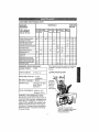
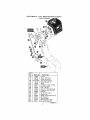
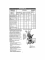
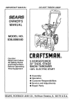
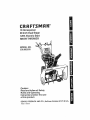
10 Horsepower
29 Inch Dual Stage
120V. Electric Start
SNOW THROWER
MODEL NO.
536.882650
Caution:
Read and follow all Safety
Rules and Operating
Instructions
before first use
of this product,
SEARS,
ROEBUCK
760211 10/01f96
AND CO., Hoffman
Estates 60179 U.S.A.
Table of Contents
Warranty
Safety Rules
Contents of Shipping Carton
Assembly
Operation
Maintenance
LIMITED
TWO-YEAR
2
2
2-4
4-5
5-9
I0-!4
t 5- t7
WARRANTY
Service and Adjustments
Storage
Troubleshooting
Snow Thrower Repair Parts
Engine Repair Parts
Spanish(Espa5ol)
Parts Ordering!Service
Back
ON CRAFTSMAN
SNOW
18-23
24
25
26-38
39-42
43-69
Cover
THROWER
For two years from the date of purchase, when this Craftsman Snow Thrower is maintained, lubricated, and tuned up according to the operating and maintenance instructions in the owner's manual, Sears will repair, free of charge, any defect in material or
workmanship.
If this Craftsman Snow Thrower is used for commercial or rental purposes, this warranty applies for only 90 days from the date of purchase.
This warranty does not cover the following:
• items which become worn during normal use, such as spark plugs, drive belts and
shear pins
• Repairs necessary because of operator abuse or negligence, including bent crank
shafts and the failure to maintain the equipment according to the instructions contained in the owner's manual.
WARRANTY SERVICE IS AVAILABLE BY RETURNING THE CRAFTSMAN SNOW
THROWER TO THE NEAREST SEARS SERVICE CENTER/DEPARTMENT
IN THE
UNITED STATES. THIS WARRANTY APPLIES ONLY WHILE THIS PRODUCT IS IN
USE IN THE UNITED STATES.
This warranty gives you specific legal rights, and you may also have other rights which
may vary from state to state.
Sears, Roebuck and Co., D817WA, Hoffman Estates, IL 60179
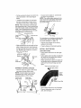
Look for this symbol to point out important safety precautions.
It means-ATTENTION!!! Become alert!!! Your safety is involved,
Z_ CAUTION: Always disconnect spark
while it is operating Never allow adults
to operate the snow thrower without
plug wire and place wire where it cannot
proper instruction Do not carry passencontact spark plug to prevent accidental
gers.
starting when setting-up, transporting,
adjusting or making repairs.
3. Keep the area of operation clear of all
persons, particularly small children and
IMPORTANT: Safety standards require
pets.
operator presence controls to minimize the
risk of injury. Your snow thrower is
4
Exercise caution to avoid slipping or
equipped with such controls Do not attempt
falling, especially when operating in
to defeat the function of the operator
reverse.
presence control under any circumstances
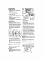
PREPARATION
TRAINING
1
Thoroughly inspect 1he area where the
snow thrower is to be used and remove
1
Read the operator's manual carefully.
Be thoroughly familiar with the controls
all doormats, sleds, boards, wires and
and the proper use of the snow thrower.
other foreign objects
Know how to stop the snow thrower and 2
Disengage all clutches before starting
disengage the controls quickly.
the engine (motor)
2. Never allow children to operate the
3
Do not operate the snow thrower
snow thrower and keep them away
2
without
wearing
adequate
winter
outer
garments..
Wearfootwear
thatwill
improve
footing
onslipper,/surfaces.
4, Handle
fuelwithcare;itishighly
flammable.
6
(a) Useanapproved
fuelcontainer
(b} Neverremove
fueltankcaporadd
fueltoa running
engine
orhot
engine.
(c) Fillfueltankoutdoors
withextreme7.
care.Never
fillfueltankindoors.
(d) Replace
fueltank
capsecurely
and
wipeupspilled
fuel
(e) Never
storefuelorsnowthrower 8.
withfuelinthetankinside
ofa
building
where
fumesmayreach
anopenflameorspark
(f) Check
fuelsupply
before
each use,
allowing space for expansion as
the heat of the engine (motor) and/
or sun can cause fuel to expand
5.
Use extension cords and receptacles
as specified by the manufacturer for all
snow throwers with electric drive
motors or electric starting motors
6. Adjust the snow thrower height to clear
gravel or crushed rock surfaces.
7
Never attempt to make any adjustments
while the engine (motor) is running
(except when specifically recommended by the manufacturer),
8.
Let engine (motor) and snow thrower
adjust to outdoor temperatures before
starting to clear snow.
9. Always wear safety glasses or eye
shields during operation or while
performing an adjustment or repair to
protect eyes from foreign objects that
may be thrown from the snow thrower.
OPERATION
1.
2.
3.
4
5.
Do not operate this machine if you are
taking drugs or other medication which
can cause drowsiness or affect your
ability to operate this machine.
Do not use this machine if you are
mentally or physically unable 1o operate
this machine safely.
Do not put hands or feet near or under
rotating parts Keep clear of the
discharge opening at all times.
Exercise extreme caution when operating on or crossing gravel drives, walks,
or roads Stay alert for hidden hazards
or traffic.
After striking a foreign object, stop the
engine (motor), remove the wire from
the spark plug, disconnect the cord on
electric motors, thoroughly inspect the
snow thrower for any damage, and
repair the damage before restarting and
operating the snow thrower
If the snow thrower should start to
vibrate abnormally, stop the (motor) and
check immediately for the cause
Vibration is generally a warning of
trouble..
Stop the engine (motor) whenever you
leave the operating position, before
unclogging the auger/impeller housing or
discharge guide, and when making any
repairs, adjustments, or inspections
When cleaning, repairing, or inspecting,
make certain the auger/impeller and all
moving parts have stopped Disconnect
the spark plug wire and keep the wire
away from the plug to prevent accidental
starting.
9.. Take allpossible precautions when
leaving the snow thrower unattended
Disengage the augerlimpeIler, stop
engine, and remove key
10 Do not run the engine indoors, except
when starting the engine and for
transporting the snow thrower in or out
of the building. Open the outside doors;
exhaust fumes are dangerous (containing CARBON MONOXIDE, an ODORLESS and DEADLY GAS).
tl
Do not clear snow across the face of
slopes. Exercise caution when changing
direction on slopes. Do not attempt to
clear steep slopes
12 Never operate the snow thrower without
proper guards, plates or other safety
protective devices in place.
13 Never operate the snow thrower near
glass enclosures, automobiles, window
wells, drop-offs, and the like without
proper adjustment of the snow discharge
angle Keep children and pets away.
14.. Do not overload the machine capacity by
attempting to clear snow at too fast a
rate.
15. Never operate the snow thrower at high
transport speeds on slippery sudaces..
Look behind and use care when
backing.
16 Never direct discharge at bystanders or
allow anyone in front of the snow
thrower
17. Disengage power to the auger!impeller
when snow thrower is transportedor not
in use.
18 Use only attachmenls and accessories
approved by the manufacturer of the
snow thrower (such as tire chains,
electric start kits, etc).
19, Never
operate
thesnow
thrower
without
goodvisibility
orlght.Nways
be sure of your footing, and keep a
firm hoId on the bandies. Walk; never
run,
MAINTENANCE
1,,
2,
AND STORAGE
Check shear bolts and other bolts
frequently for proper tightness to be
sure the snow thrower is in safe
working condition
Never store the snow thrower with fue!
in the fuel tank inside a building where
ignition sources are present such as
hot water and space heaters, clothes
A
ZL_ WARNING:
The engine exhaust
from this product contains chemicals
known 1o the State of California to cause
cancer, birth defects or other reproductive
harm.
/_
WARNING:
This snow thrower is for
use on sidewalks, driveways and other
ground level surfaces,
Caution should be exercised while using on
steep sloping surtaces, DO NOT USE
SNOW THROWER ON SURFACES
ABOVE GROUND LEVEL such as roofs of
residences, garages, porches or other such
structures or buildings
4,
5,,
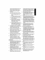
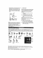
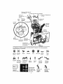
Contents
el Parts Bag
1 . Owner's Manual (not shown)
2 - Parts Bags (not shown)
Non Assembly parts
* 2 - Spare Shear Bolts
1t4-20 x 1-3f4 In,,
"2 - Spare t/4 - 20 Locknuts
2- 3/8 ln. Hex Nut
2-3/8-16 x 2 In, Hex Head Bolt
2 -3/8 In,, Flatwashers
2 - 3/8 in., Loekwasher
I]lui]ll]lu-"l-"l
Iilllltllllllllltllllllltlillllllllllllllllllllllllllllllllllllfll
'2 * Spare Spacers
1 * Starter Motor Cord
I -11/32 Inch
Flal washer
1
1- Cable Tie
Parts
packed
separately
in carton
(not shown
2 - Ignition Keys
full size)
1 - container_.k
5W30 oil
(Attached to engine in ptastic bag)
"__
1 - Mid-Crank Rod
1 - Speed Control Rod
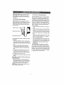
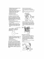
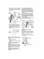
CAUTION: Afways wear safety
glasses or eye shields while assembling
snow thrower_
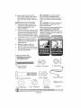
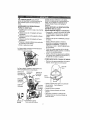
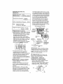
The figure befow shows the snow thrower
completely assembled
References to the right or left hand side
of the snow thrower are from the view_int
of the operator's position behind the unit,
TOOLS
REQUIRED
FOR ASSEMBLY
1 - Knife to cut carton and plastic ties
2 - 1/2 inch wrenches (or adjustable
wrenches)
2 - 9/t6 inch wrenches (or adjustable
wrenches)
Auger Drive Lever
Remote Chute Deflector Lever
Speed Shifter Lever
Drive
Lever
t - Pliers (to spread cotter pin)
IScrewdriver
Crank
Assembly
t - Air pressure gauge
1 - Measuring tape or ruler
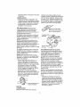
The figure below shows the snow thrower in
the shipping carton.
Cable
Deflector
Height
Adjust
Skids
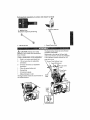
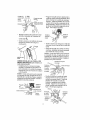
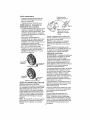
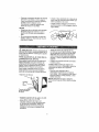
HOW TO SET UP YOUR SNOW
INSTALL THE UPPER HANDLE
THROWER
• Cut ties securing the clutch control cables
and remote chute control cable to the
lower handle. Lay cable away from
handles
• Remove the bolts securing the upper
handles to the lower handles See figure
below NOTE: Discard white plastic
washer used for shipping purposes on
the right side,
• Remove upper handle assembly and
place it into operating position Upper
handle should be on the outside of the
lower handle
• Locate and remove container of 5W30 oil
and parts bag found in parts box.
• Remove top pallet from carton
• Cut and discard the plastic ties securing
the mid-chute rod and speed control rod
to the pallet, place them aside Discard
pallet
, Cut all four corners of the carton from top
to bottom and lay the panels flat
• Cut the bands holding the snow thrower
to the lower pallet,
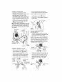
ASSEMBLE
SNOW CHUTE
• Remove
below
back carriage bolt, see figure
NOTE: Unless you have the assistance of
another person, it may be easier to install one
side of the handle at a time
NOTE: Make sure the cables are not
caught between the upper and lower
handle
• Replace the bolts, flatwasher, Iockwasher,
and hex nuts removed earlier into the top
holes Do not tighten.
Carriagem
Bolt
//,,Upper
• Tilt chute back into operating 3osition
See figure below
handle
Remove
J3/8
Flatwasher
3/8' hex Nu_
Chute in
J
operating
position
}_3/8
X 2" Screw
318"Lockwasher
Carriage--
_
Bolt
• Replace carnage boll
• Tighten carriage bolt securely. NOTE:
Check all bolts in chute ring for tightness,
• Remove and discard packaging used to
protect chute
• Install hardware supplied in parts bag
(screws, flatwashers, Iockwashers, and
hex nuts) into the lower holes
• Tighten all four bolts
• Replace protective caps onto screws in
upper holes
• Connect "Z" fitting into remote chute
CONNECT
HEADLIGHT
control bracket as shown in figure below.,
- Connect
wireharness
terminals
to
headlight
assembly
locatedundercontrol • Push remote chute control lever into
panelasshowninthefigurebelow
"Chute Deflector Down" "_ position,
• Tieheadlight
cabletoIowerhandles
with
theplastic
cabletiesupplied
intheparts • Cut tie strap on chute deflector as shown
in figure below
bagbythreading
thepointed
endsofthe
tiethrough
thesquare
endandpulling
tightlyaround
theheadfight
cableand
handles.
Seefigurebelow
NOTE:Onesideoftheplastic
tiehassmall
notches
init,whiletheothersideissmooth
Thenotched
sidemustbeontheinsideof
theloopwhichisformed
whentheendsare
puttogether..
Chute
Dellector
Wire Harness
Termina_
.__
Headlight
Cable
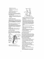
INSTALL MID-CHUTE
ROD
(set aside earlier)
• Carefully remove cotter pin and clevis
pin from universal joint in the upper crank
rod as shown in first figure below.
NOTE: If this removes the universal joint
and universal joint pin. Place universal joint
into yoke of upper crank rod lining up large
holes., insert universal joint pin (ensure
opening in universal joint pin is in line with
small openings in universal joint)
Wire
Harness
Terrains
Cable Tie
\Lower
Handle
Upper
Clevis Pin
CONNECT
REMOTE
. Push remote chute control lever into
"Chute Deflector Up" _
___//Cotter
• Snap remote chute control cable into
remote chute bracket, see figure below
Bracket
Universal
position
• Feed "Z" fitting through hole in remote
chute bracket as shown in figure below.
Chute
Control
Remote '__
Pin
, Place yoke of open end of mid-crank rod
around universal joint in upper crank rod.
Insert clevis pin through assembly and
secure with cotter pin, Spread ends of
cotter pin to lock in place See figure
below,
Bracket
_/ (_\
Remote Chute
_._ _-_ote
Chu,e
Mid-Crank
Red
°Z"Fittin_
Rod
:rsal
Joint Pin
CHUTE
t Cable
'Crank
Rod
- Cut tie securing the lower crank rod to the
chute rod bracket See second figure
below.
•
Carefully remove cotter pin and clevis
pin from universal joint in lower end of
mid-crank rod as shown in figure below
. Connect control cables to control lever
as shown in figure below
NOTE: The control cables attached to the
auger clutch lever and traction clutch lever
may need to be adjusted before you use
your snow thrower
NOTE: If this removes the universal joint
and universal ioint pin Place universal joint
into yoke of upper crank rod lining up large
holes Insert universal joint pin (ensure
opening in universal joint pinis in line with
small openings in universal joint)
"--..._"_"_.._ Universal Join! Pin
Lower E__-_,/_Universal
Joint
'Z" Fitting
For instructions on checking or adjusting the
control cables, (See To Adjust Clutch Corn
trol Cables paragraph on page 19)
Cran_
• Rot! the snow thrower off the skid by
pulling on the handle.
• Slide universal joint in mid*crank rod into
yoke of lower crank rod Insert clevis pin
through assembly and secure with cotter
pin,, Spread ends of cotter pin 1o lock in
place, See next figure
Crank Rod t_.
CONNECT
CONTROL
CABLES
INSTALL SHIFTER ROD
(set aside earlier)
• Place speed shifter lever into sixth gear
position
. Insert speed control rod (the end with the
90 '_bend) into the speed select bracket
lower hole. see next figure
• Attach speed control rod to the speed select bracket with one flatwasher and one
cotter pin found in parts bag, see next
figure
View lrorn the left side o! unit
ixth gear position
• Remove wrap from upper handle which
was used to protect clutch levers
NOTE: If control cables have become
unattached from motor mount frame,
reconnect cables as shown below
Traction drive
spring (Long)
• Properly dispose ol discarded packing
Speed
Select
Bracket
Auger drive
spring (Short)
\
Auger
drive
Speed Control Rod
spring
cable
spring
lever
• Move speed shifter lever into Rlposition
• Remove lockwasher and nut from ball
joint, see next figure
Attach
balljointtospeedselectleverwith
tockwasher
andnut,thentightenSee
figurebelow.
Thespeedcontrol
rodand
balljointhavebeenpreadjusted
atthe
factory
andshould
notrequire
readjustment.
,i
CHECKLIST
Before you operate your new snow thrower,
to ensure that you receive the best pedormance and satisfaction from this quality
product, please review the folbwing
checklist:
v"
A_Iassembly instructions have been
completed
,# The discharge chute rotates freely
4" No remaining loose parts in carton,
except for extra shear bolt assembly
parts,
While learning how to use your snow
thrower, pay extra attention to the follow{rig
important items:
JJ Engine oil is at proper level
J,I Make sure gas tank is filled properly
with clean, fresh, unleaded gasoline
J,f Become familiar with all controls-their
location and function Operate controls
before starting engine
Speed
Control
Rod-....._
_'--Ball
Joint
__,!e
peed
e_ect
vet
NOTE: Your snow thrower is equipped ,with
height adjust skids (see second figure on
page 5) on the outside of the auger housing
To adiust the skid height for different
conditions, (see To Adjust Skid Height paragraph on page 18),
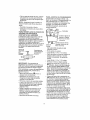
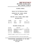
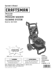
KNOW YOUR SNOW THROWER
READ THIS OWNER'S MANUAL AND SAFETY RULES BEFORE OPERATING YOUR
SNOW THROWER Compare the illustrations with your SNOW THROWER to familiarize
yourself with the location of various controls and adjustments Save this manual for future
reference
÷
Engine Choke Of!
Run
Auger Drive
Clutch
Discharge
chute-Right
Fast
Slow
Forward Reverse
Chute
Deflector
Down
Stop
Fuel
Oil
Primer
Button
Engage Traction
Drive
Clutch
Discharge
chute-Left
Ignition
Key
insert to
run
pu_lout
to stop
Chute
Defleclor Up
The operation of any snow thrower can result in foreign obiects being thrown into the
eyes, which can result in severe eye damage Always wear safety glasses or eye shields
while operating the snow thrower
We recommend standard safety glasses or a wide vision safety mask for over your
glasses, availabte at Sears Retail Stores or Service Centers
@
Speed Shifter Lever
Remote Chute Contrei
Drive Lever
Auger Drive
Electric
Button
Ignition
arge
Chute
Control
Auger
Height Adit
:r Bolt
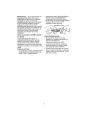
Auger Drive Lever - Starts and stops the
auger and impeller (snow gathering and
throwing),
Traction Drive Lever - Propels the snow
thrower forward and in reverse
Ignition Key - Must be inserted to start the
engine
Primer Button - Injects fuei directly into the
carburetor mani!old for fast starts in cold
weather,
Headlight - Turns on whenever engine is
running,
Speed Shifter Lever - Selects the speed of
snow thrower (6 speeds forward and 2
speeds reverse)
Crank Assembly - Changes the direction of
snow throwing through the discharge chute,
Chute Deflector - Changes the distance
the snow is thrown
Recoil Starter Handle
manually,
Discharge Chute - Changes the direction
the snow is thrown,
Choke Control - Used to start a cold engine,
Height Adjust Skids - Adjusts the ground
clearance of the auger housing,
Z_
- Starts the engine
Throltte ControlControls the engine
speed,
Electric Starter Button - Used to start the
engine using the 120 V electric starter,
Remote Chute Controt Lever- Push forward to discharge snow high and far, Pull
remote lever back to discharge snow down
Shear Bolts - Are special bolts that are designed to break (to protect the
machine) if an object becomes lodged in
the auger housing Use of a harder bolt will
destroy the protection provided by the shear
bolt.
CAUTION:
Read owner's manual before operating machine Never direct discharge
toward bystanders Release the auger control bar and stop the engine before unclogging discharge chute or auger housing and before leaving the machine,
HOW TO USE YOUR SNOW
THROWER
- Engage the traction drive lever as shown
in first figure on this page, left hand As
the snow thrower starts to move, maintain
a firm hold on the handles, and guide the
snow thrower along the clearing path Do
not attempt to push the snow thrower.
• To move the snow thrower backward,
move the speed shifter lever into first or
second reverse and engage the traction
drive lever (left hand)
IMPORTANT: Never move the speed shifter
lever while the traction lever is down
TO STOP YOUR SNOWTHROWER
• To stop throwing snow, release the auger
drive lever (see figure below)
• To stop the wheels, release the traction
drive lever
- To stop the engine, push the throttle control lever to off and pull out (DO NOT
TURN) the ignition key, see figure on
page 10
TO THROW SNOW
• Push down the auger drive lever, see first
figure on this page
• Release to slop throwing snow
TO USE WHEEL
Traction Drive Lever
TO CONTROL
SNOW
Auger Drive Lever
DISCHARGE
LOCKOUT
PIN
• The left hand wheel is secured to the axle
with a klick pin, see figure below, This
unit was shipped with this klick pin in the
locked position (klick pin through hole in
wheel),
• Turn the crank assembly to set the direction of the snow throwing.
• Adjust snow chute deflector to set the
distance Push remote lever forward to
discharge snow down Putt remote lever
back to discharge snow high and far See
figure below
2-Wheel Drive
Locked
Posilion
• For ease of maneuverability in light snow
conditions, disconnect the ktick pin from
the wheel locked position and push into
the single wheel drive position (klick pin
through axle hole only), see next figure
NOTE: Make sure that the klick pin is in the
single wheel drive position, through axle
only and not through the hole in wheel
TO MOVE FORWARD AND
BACKWARD
To shift, release the traction drive lever
and move the speed shifter lever to the
speed you desire Ground speed is determined by snow conditions Seiect the
speed you desire by moving the speed
shifter lever into the appropriate area on
the control panel
Speeds 1, 2 - Wet, Heavy, Extra Deep
Speed 3 - Light
Speed 4 - Very Light
Klick Pin
Single
Wheel
Drive
Unlocked
Position
Speeds 5, 6 -Transport only
1t
BEFORE STARTING THE ENGINE
• If the snow thrower must be moved without the aid of the engine, it is easier to pull
the snow thrower by the handles rather
than pushing.
• Before you service or start the engine, familiarize yourself with the snow thrower.
Be sure you understand the function and
location of all controls.
run until the fuel lines and carburetor are
empty Use the carburetor bowl drain to
empty residual gasoline from the float chamber Use fresh fuel next season (See
Storage instructions on page 23 and 24 for
additional information)
NOTE: Check tension of clutch cables before starting the engine (See To Adjust The
Control Cables paragraph on page 19).
• Be sure that all fasteners are tight.
- Make sure the height adjust skids are
properly adjusted (See To Adjust Skid
Height paragraph on page 18).
- Check tire pressure (14 to t7 pounds)_
See side of tire for maximum inflation. Do
not exceed listed maximum pressure
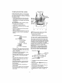
FILL OIL
NOTE: Oil must be changed after the first 2
hours of operation to extend engine life.
For extreme cold operating conditions of 0°F
and below, use a partial synthetic 0W30
motor oil for easier starting
Never use engine or carburetor cleaner
products in the fuel tank or permanent damage may occur
Fill the fuel tank with clean, fresh, unleaded
grade automotive gasoline. Be sure that the
container you pour the gasoline from is
clean and free from rust or other foreign particles, Never use gasoline that may be stale
from long periods of storage in the container.
This snow thrower was shipped with a container of 5W30 motor oil. This oil must be
added to the engine before operating, Remove the of! fill cap/dipstick and fill the crank
case to (FULL) line on dipstick (26 ounces)
(see figure below),
CAUTION: Gasoline is flammable
and caution must be used when handling or storing it.
Do not fill fuel tank while snow thro_ver is
running, when it is hot, or when snow
thrower is in an enclosed area
Oil FilltDipstick
"_' '_O1' t7
Keep away from open flame or an electrical
spark and DO NOT SMOKE while filling the
fuel tank,
,,
Never fill the tank completely. Fill the tank
to within 1/4"- 1/2" from the top to provide
space for expansion of fuel
Always fill fuel tank outdoors and use a funnel or spout to prevent spilling,
Make sure to wipe up any spilled fuel before
starting the engine,
NOTE: Oil levelmusl be
NOTE: Engine may already contain some
residual oil. Check frequently when filling the crankcase. Do not over fill,
Store gasoline in a clean, approved container and keep the cap in place on the container,
Tighten the fill cap/dipstick securely each
time you check the oil level
TO STOP ENGINE
, To stop engine, move the throttle control
lever to _ (STOP) position and remove
key Keep the key in a safe place. The
engine will not start without the key.
NOTE: DO NOT turn key.
FILL GAS
WARNING: Experience indicates that alcohol blended fuels (called gasohol or those
using ethanol or methanol) can attract moisture which leads to separation and formation
of acids during storage. Acidic gas can
damage the fuel system of an engine while
in storage.
TO START
ENGINE
(Electric
Starter)
Be sure that the engine has sufficient oil.
The snow thrower engine is equipped with a
120 volt A C. electric starter and recoil
starter. Before starting the engine, be certain that you have read the following information:
To avoid engine probtems, the fuel system
should be emptied before storage for 30
days or longer,. Start the engine and let it
12
.4k CAUTION:
This starter is equipped
ZJ_ with a three-wire power cord and plug
and is designed to operate on 120 volt AC
household current It must be properly
grounded at all times 1o avoid the possibility
of electrical shock which may be injurious to
operator, Follow all instructions carefully as
set forth in the "To Start Engine" section
Determine that your house wiring is a threewire grounded system, Ask a licensed electrician if you are not sure If your house
wire system is not a three-wire system, do
not use this electric starter under any conditions. If your system is grounded and a
three-hole receptacle is not available at the
point your starter will normally be used, one
should be installed by a licensed electrician
When connecting I20 volt AC power cord,
always connect the cord to the switch box
on the engine first, then plug the other end
into the three-hole grounded receptacle.
When disconnecting power cord, always
unplug the end in the three-hole grounded
receptacle first
stop automatically and can be restarted
only when il has cooled to a safe
temperature (a wait ot about 5 to 10
minutes is required),
• When the engine starts, release the
starter button and slowly rotate the choke
to (OFF) position, If the engine falters,
rotate the choke to(FULL) and then
gradually to (OFF)
• Disconnect the power cord from the
receptacle first and then from the switch
box on engine
NOTE: Allow the engine to warm up for a
few minutes because the engine will not develop full power until it reaches operating
temperature_
• Run the engine al full throttle '_ (FAST)
when throwing snow.
TO START
ENGINE
(Recoil
Starter)
Be sure that the engine has sufficient oil
The snow thrower engine is equipped with a
recoil starter.. Belore starting the engine, be
certain that you have read the following intormation:
COLD START
• Be sure the auger drive and traction drive
levers are in the disengaged (released)
position.
• Move the throttle control to '_ (FAST)
position See figure on page 10
• Remove the keys from the plastic bag
Insert one key into the ignition slot. Be
sure it snaps into place, DO NOT TURN
KEY Keep the second key in a safe
place.
• Rotate the choke knob to (FULL) choke
position, See figure on page 10,
• Connect the power cord to the switch box
on the engine.
• Plug the other end of the power cord into
a three-hole, grounded !20 volt A C
receptacle,
COLD START
. Be sure the auger drive and traction drive
levers are in the disengaged (released)
position,
• Move the throttle control to '_ (FAST)
position See figure on page 10 for location
• Remove the keys from the plastic bag Insert one key into the ignition slot, Be sure
it snaps into place. DO NOT TURN KEY
Keep the second key in a safe place
• Rotate the choke contro! to (FULL) choke
position See figure on page t0
• Push the primer button, see figure on
page 10, while covering the vent hole as
follows: (Remove linger from primer button between primes)
Do not prime if temperature is above
50oF
o Push the primer button while covering the
vent hole as follows: (Remove finger from
primer blitton between primes) See
figure on page I0 for tocalion,
Do not prime if temperature is above
50°F,
Two times il temperature is 50_F to 15°E
Four times if temperature is below 15°F,
• Pull the recoil starter handle rapidly. Do
not allow the handle to snap back, but atlow it to rewind slowly while keeping a
firm hold on the starter handle
Two times if temperature is 50°F to t5°F.,
Four times if temperature is below 15_F
• Push clown on the starter button until the
engine starts, Do not crank lor more than
10 seconds at a time. This electric starter
is thermally protected, If overheated it will
13
• Astheengine
warms
upandbegins
tooperateevenly,
rotate
thechoke
control
slowlytothe(OFF)
positionIftheengine
falters,
returnto(FULL)
choke,
then
slowlymove
tothe(OFF)position
NOTE:
Allowtheengine
towarmupfora
fewminutes
because
theengine
willnotdevelopfullpoweruntilitreaches
operating
temperature
• Runtheengine
atfullthrottle ._ (FAST)
when throwing snow
WARM START
If restarting a warm engine after a short
shutdown, leave choke at (OFF) and do not
push the primer button. If the engine fails to
start, follow the Cold Start instructions
above,
FROZEN RECOIL STARTER
If the starter is frozen and wilt not turn
engine:
. Pull as much rope out of the starter as
possible,
• Release the starter handle and let it snap
back against the starter.
If the starter still fails to turn engine, repeat
the two previous steps until the starter engages Then continue with the directions for
coJd start
To help prevent possible freeze-up of recoil
starter and engine controls, proceed as follows after each snow removal job
• With the engine running, putt the starter
rope hard with a continuous full arm
stroke three or four times,, Pulling of
starter rope will produce a loud clattering
sound This is not harmful to the engine or
starter
• With the engine not running, wipe all
snow and moisture from the carburetor
cover in area of control levers, Also move
throttle control, choke control, and starter
handle several times
_
CAUTION:
Never run engine indoors
or in enclosed, poorly ventilated areas.
Engine exhaust contains carbon monoxide,
an odorless and deadly gas, Keep hands,
feet, hair and loose clothing away from any
moving parts on engine and snow thrower,
WARNING:
Temperature of muffler and
nearby areas may exceed I50 ° F Avoid
these areas
DO NOT allow children or young teenagers
to operate or be near snow thrower while it
is operating,
Z_
CAUTION: Do no attempt to remove
any item that may become lodged in
auger without taking the following precautions:
• Release auger drive and traction drive
levers.
•
o
.
Move Ihrottle lever to stop position.
Remove (DO NOT TURN) ignition key
Disconnect spark plug wire
Do not place your hands in the auger or
discharge chute, Use a pry bar,
SNOW THROWING TIPS
• For maximum snow thrower efficiency in
removing snow, adjust ground speed,
NEVER the throttle Go slower in deep,
freezing, or wet snow,, If the wheels slip,
reduce forward speed The engine is designed to deliver maximum performance
at full throttle and should be run at this
power setting at all times. Most efficient
snow blowing is accomplished when the
snow is removed immediately after it falls,
• For complete snow removal, slightly overlap each path previously taken, Use more
overlap in deep snow to prevent overloading
• The snow should be discharged down
wind whenever possible In windy conditions, lower the chute deflector to direct
discharged snow close to the ground,
where it is less likely 1o blow into unwanted areas
- For normal usage, set the skids so that
the scraper bar is t/8" above the skids
For extremely hard-packed snow surfaces, adjust the skids upward so that the
scraper bar touches the ground.
• On gravel or crushed rock surfaces, set
the skids at 1-t/4" below the scraper bar
(See To Adjust Skids Height paragraph on
page 18) Stones and gravel must not be
picked up and thrown by the machine,
• After the snow throwing job has been
completed, allow the engine to idle tora
few minutes, which will melt snow and accumulated ice off the engine
- Clean the snow thrower thoroughly after
each use
• Remove ice and snow accumulation and
all debris from the entire snow thrower,
and flush with water (if possible) to remove all salt or other chemicals, Wipe
snow thrower dry,
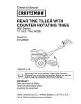
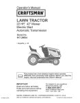
CUSTOMER RESPONSIBILITIES
SERVICE
RECORDS
SCHEDULE
Fill in dates as
you complete
regular service
Tigh!en AIJ Screws & Nuts
Lubricate
SERVICE
DATES
A.er BeforeA_
EVo_E_or_
E_e_ E_ch Before
iirst 2 Each
Hours Use
5
Hours
,v"
Needed:
,
_
J
t0
Hours
25
Hours
Season
Storage
........
p,,"
Pivo[Poinls
LubricaEe Auger Shaft iSee
Shear Boll Replacement
=
pJ
=
_
t,"
.........
=
Lubricale Disc Drive PIate Zerk
Check Spark Plug
,_
Check Engine Oil Lever
it'
Change Engine Oil
p,_
....
_
Check FueI
=
....
_
................... =
;
;
;I'
Drain Fuei
_,_
Check Auger Clutch Cabte
Adjustment (See Cabie Adj)
Check Traction Clutch Cable
Adjustment (See Cable Adj)
_
Check Drive Belts
_
PRODUCT
......
_
_
...........
•
=
-
.
.......rE
..
!
_
!
[,,
_
HORSE POWER:
SPECIFICATIONS
10 HP
Some adjustments will need to be made periodically to properly maintain your snow
thrower
DISPLACEMENT:
21 82 cu in,
LUBRICATION
GASOLINE CAPACITY:
OIL (26 oz, Capacity) :
SPARK PLUG:
VALVE CLEARANCE:
4 quart
(unleaded)
5W-30
CHART
Lubricate
Disc Drive
Plate Zerk
with a Hi
Champion RJ19LM
(Gap 030) or
Equivalent
Temp EP
Moiy Grease
Intake: 0 !0 In,
Exhaust: .010 tn,
GENERAL
RECOMMENDATIONS
The warranty on this snow thrower does not
cover items that have been subjected to operator abuse or negligence To receive full
value from the warranty, the operator must
maintain the snow thrower as instructed in
this manual The above chart is provided to
assist the operator in properly maintaining
the snow thrower,
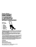
Lub_'icale the Auger Shaft
Coat with a clinging _ype grease
such as Lubriplate or fiber
impregnated grease
15
SNOW THROWER
AFTER
FIRST
Shaff
Friction
Wheel
USE
Disc
• Check for any loose or damaged parts
after each use
(Require
No
LubricatiS'n)
• Tighten any loose fasteners
• Check and maintain the auger,
AFTER EACH USE
• Remove all snow and slush off the snow
thrower to prevent freezing of auger or
controls
Friction
Wheel
Place coin in gap
between lriclion
wheel and disc drive
pta_e
I
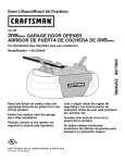
SNOW TH ROWER
Zerk
• To grease zerk, use a hand grease gun,
lubricate with a Hi Temp EP Moly grease
See inset of figure above DO NOT over
fill or allow grease to come in contact with
the disc drive plate or friction wheel or
damage will result Fill zerk only until
grease becomes visible be}ow bearing assembly located under grease zerk see insert above,,
IMPORTANT: Remove coin and ensure that
a gap exists between friction wheel and disc
drive p_ate.
• For storage or when replacing shear
bolts, remove shear bolts and lubricate
auger shaft zerks Rotate augers several
times on the shaft and reinstall the shear
bolts,
NOTE: Clean all excess grease found on
friction disc hub
CAUTION: Do not allow grease to contact
friction wheel and disc drive plate
, See Lubrication Chart diagram on page
15 for lubrication points and type of lubricant,
- EVERY
}
E_:_}--Grease
grease
should be v_sibte
• Remove the bottom panel (see second
figure on page 21 )
o Turn disc drive plate clockwise by hand
until grease zerk is clearly visible at front
center. See next figure,
• Place a coin or (a shim of equal thickness) between the rubber friction wheel
and disc drive plate to prevent rubber friction wheel contacting the drive disc,
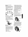
EVERY 10 HOURS
• Auger Shaft- Using a hand grease gun,
lubricate the auger shaft zerk fittings (See
figure below) every ten (10)operating
hours. Each time a shear bolt is replaced
(See To Replace Auger Shear Bolt on
page 22), the auger shaft MUST be
greased,.
LUBRICATION
Grease
Bearing
• Check controls to make sure they are
functioning properly
• I! any parts are worn or damaged, replace
immediately.
LUBRICATION-
%,
LUBRICATION-
BEFORE STORAGE
• Remove both wheels, grease (any automotive type grease) both axles, see figure
below, and replace wheels Do this at
least once a year and/or prior to storage
25 HOURS
• Lubricate Disc Drive Plate ever,/twentyfive (25) hours and at the end of the season and/or before storage
To Lubricate:
, Position speed selector lever in first gear.
,' Stand the snow thrower up on the auger
housing end,
t6
LUBRICATION
• HexShaftandGears
- Hexshaftand
gearsrequire
nolubrication.
Allbearings
andbushings
arelifetime
lubricated
and
require
nomaintenance
NOTE:Anygreasing
oroilingoftheabove
components
cancause
contamination
of
thefriction
wheel,tfthediscdriveplateor
friction
wheelcomes
incontact
withgrease
oroil,damage
tothefriction
wheelwillresult.
Should
grease
oroilcomeincontact
with
thediscdriveplateorfriction
wheel,
besure
tocleantheplateandwheelthoroughly.
NOTE:Forstorage,
thehexshaftand
gearsshould
bewipedwith5W-30
motoroil
toprevent
rustingSeefirstfigure
onthis
page.
• Auger
GearBox-Theaugergearboxis
lubricated
atthefactory
andshould
not
require
additional
lubrication.
Ifforsome
reason
thelubricant
should
leakout,orif
theaugergearboxhasbeenserviced,
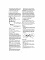
OIL RECOMMENDATION
Only use high quality detergent oil rated
with API service classitication SG. Select
the oil's viscosity grade according to your
expected operating temperature:
add Lubripfate No. 630-AA or equivalent.
Maximum 3-1/4 ounces should be used
Remove filler plug as seen in figure below
once a year. If grease is visible, do not
add.. If grease is not visible, use a piece
of fine wire like a dipstick, to check if
there is grease in the gearbox. Add
grease if necessary Reinstall gear box
filler
NOTE: For extreme cold operating conditions of 0° and below, use a partial synthetic
0W30 motor oil for easier starting.
Change the oil after first two (2) hours of
operation, every twenty-five (25) hours
thereafter, and at the beginning of each
season
• Position the snow thrower so that the oil
drain plug is at the lowest point on the engine.. Remove the oil drain plug and the
oil fill cap/dipstick. Drain the oil into a suitable container Oif will drain more freely
when warm.
• Replace the oil drain plug and tighten securely.
SPARK PLUG
• Make sure that the spark plug is tightened securely inlo the engine and the
spark plug wire is attached Io the spark
plug
, II a torque wrench is available, torque
plug to 18 to 23 foot pounds.
• Clean the area around the spark plug
base before removal to prevent dirt from
entering the engine
• Clean the spark plug and reset the gap
periodically at 030 inch.
r Box Filler
Plug
ENGINE
LUBRICATION
Check the crankcase oil level (see figure below) before starting the engine and after
each five (5) hours of continuous use Add
S.AE 5W30 motor oi! as needed Tighten
lill cap/dipstick securely each time you
check the oil level
17
A
CAUTION:
Always disconnect the
spark plug wire and tie back away from
the plug before making any adjustments
or repairs
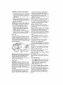
TO ADJUST SKID HEIGHT
This snow thrower is equipped with two
height adjustment skids, located on the outside of the auger housing (see figure below) These skids elevate the front of the
snow thrower
Auger Housing
Height Adjust Skids
Skid Mounting N
For normal hard surfaces, adjust the skids
as lollows:
• Check tire pressure (14 to I7 pounds).
See side ol tire for maximum inflation. Do
not exceed maximum pressure on side of
tire,
- Place the extra shear bolts supplied
(found in parts bag) under each end of
the scraper bar near but not under the
skid
• Loosen the skid mounting nuts (see figure above) and adiust the skids up to
bring the front of the snow thrower down
• Re-tighten the mounting nuts
• Set the skid on the other side at the same
height
For rocky or uneven surfaces, adjust the
skids as follows:
• Raise the front o_the snow thrower by
moving the skids down This will help prevent rocks and other debris from being
picked up and thrown by the auger
NOTE: Be sure that snow thrower is set at
same height on both sides
TO ADJUST SCRAPER BAR
After considerable use, the metal scraper
bar will have a definite wear pattern The
scraper bar in coniunclion with the skids
should always be adjusted to allow t/8" between the scraper bar and the sidewalk or
area to be cleaned, The scraper bar may
have to be returned to its original lower setting to maintain the original performance
level To adjust:
• Position the snow thrower on a level surface.
• Make sure both tires are equa!ly inflated
• Loosen the carriage bolts and nuts securing the scraper bar to the auger housing
• Adjust the scraper bar to the proper position
• Tighten the carriage bolts and nuts, making sure that the scraper bar is parallel
with the working surface
- For extended operation, the scraper bar
may be reversed It the scraper bar must
be replaced due to wear, remove the carriage bolts and nuts and install a new
scraper bar
/_k CAUTION:
Be certain to maintain
proper ground clearance for your particular area to be cleared Objects such as
gravel, rocks or other debris, if struck by the
impeller, may be thrown with sufficient force
to cause personal injury, property damage
or damage to the snow thrower
TO ADJUSTTHE
CLUTCH CONTROL
CABLES
Periodic adjustment of the cables may be
required due to normai stretch and wear on
the bells To check for correct adiustment,
disconnect "Z" Fitting at clutch lever, move
clutch lever to the full forward position, just
contacting the plastic bumper The control
cables are correctly adjusted when the center of the "Z" fitting is between the center
and top of the hole and there is no droop in
the cable (see figure below), If adjustment is
necessary:
Plastic
Bumper
Control Lever
be in full
torward position
(Just Contacling
Plastic Bumper)
when checking
TO ADJUST BELTS
Belts stretch during normal use If you need
to adjust the belts due to wear or stretch,
proceed as follows:
AUGER DRIVE BELT
If your snow thrower will not discharge
snow, check the control cable adjustment, tf
it is correct, then check the condition of the
auger drive belt, it may be loose or damaged If it is damaged, replace it (See To
Replace Belts paragraph on page 20). If the
auger drive belt is loose, adjust as follows:
• Disconnect the spark plug wire_
, Remove the belt cover (See second
figure on page 20)
• Loosen the nut on the auger idler pulley
(See figure below) and move the pulley
toward the belt about t!8".
• Tighten the nut
Traction
• Remove fuel from tank, and stand blower
on end,
• Pull rubber boot off the top of the spring
Push the cable through the spring (see
figure below) to expose the threaded portion of the cable
Traction
Drive Belt
Drive Belt Drive
Idler
\
Belt Guide
Left Hand)
,Loosen nut
Belt
Guide
(Right
Jger Idler
Pulley
,tare end
Locknut
- Press the auger drive lever_ Check the
tension on the belt (opposite auger idler
pulley) The belt should deflect about
!12" with moderate pressure (See figure
below)
NOTE: You may have to move the auger
idler pulley more than once to obtain the
correct tension
• Hold the square end of the threaded portion with pliers and adjust the tocknut in or
out until the excess slack is removed,
• Pull the cable back through the spring
and connect the cable.
• Do the same for the other lever cable, if
needed.
NOTE: Whenever the traction drive or auger belts are adjusted or replaced, the
cables will need to be adjusted_
_y
.r_
Auger ldter ---"-{,..,_
Drive Pulley
..._,_'-t/2
Engaged
Pulley
_Deflection
inch
• Replace the belt cover.
• Check the clutch control cable
adjustment
• Reconnect the spark plug wire
TRACTION
Bert
DRIVE BELT
The traction drive belt (see figure below)
has constant spring pressure and does not
require adjustment,
• Replace the traction drive belt if it is slipping (see To Replace Belts paragraph on
this page),
TO REPLACE
1!4 X t/2 Ihch self4apping Screw
• Loosen the belt guides (see first figure on
this page) and pull away from the auger
drive pulley
. Remove belt from auger drive pulley,
, Remove top two bolls that secure auger
housing to motor mount frame, Loosen
bottom two bolts Auger housing and motor mount frame will separate, hinged by
bottom two bolts (see second figure on
page 21)
• Remove old belt from the auger drive pulley.,
• Position new belt on auger pulley
, Replace top two bolts, and re4ighten bottom two bolts
BELTS
The drive belts on this snow thrower are of
special construction and should be replaced
with original equipment belts available from
your nearest SEARS Store or Service Center..
You will need the assistance of a second
person while replacing the belts,
Drain the gasoline from the fue! tank by removing the fuel line at the carburetor,. Drain
the gas into a container and reinstall the
rue!line,
/_.
CAUTION:
Drain the gasoline outdoors, away from the fire or flame,
• Adjust the belt guides (see To Adjust The
Belt Guides paragraph on page 21),
• Reinstall the belt cover
AUGER DRIVE BELT
If your snow thrower will not discharge
snow, and the auger drive belt (see figure
below for location) is damaged, replace it
as follows:
, Reconnect the spark plug wire,,
TRACTION DRIVE BELT
tt your snow thrower will not move forward,
check the traction drive belt (see first figure
on this page) for wear (Check other causes
also in the Trouble Shooting Points section).
If the traction drive belt needs to be replaced, proceed as follows:
- Disconnect the spark plug wire
• Remove the belt cover (see figure above),
• Loosen the belt guides and pull away
from auger drive pulley (see first figure
on this page)
• Remove auger drive belt from auger pulley (see first figure on this page)
• Pull the traction drive bell idler pulley
away from the traction drive belt (see first
figure on this page)
• Remove the traction drive belt
• Position new traction drive belt onto traction pulley
• Pulf idler pulley away from belt, allowing
belt to be positioned onto auger pulley
Auger Drive Belt
Pulley
Traction
Drive Bell
Bett
(Right Hand)
er Drive
Pulley
Guide
(Left Hand)
Auger Idler
Pulley
- Disconnect the spark plug wire
• Remove the belt cover (see next figure ).
20
• Disconnect the spark plug wire.
• Drain the gasoline from the gas tank
• Stand snow thrower on the auger housing
end.
• Release idler pulley.. Ensure idler pulley
is properly engaged with bell
. Reinstall auger drive belt
• Adjust the belt guides and tighten mounting screws (see To Adjust The Belt
Guides paragraph on this page)
- Adjust idler on auger bell
- Reinstall the belt cover
• Remove the bottom panel (see figure be-
low),
RemoveTop Bolts
(Each Side)
, Reconnect the spark plug wire.
TO ADJUSTTHE
BELT GUIDES
There are two belt guides on your snow
thrower, a left and right After you replace
the traction drive belt, you need to adjust
one or both of the belt guides. Proceed as
follows for each belt:
Housing
÷
j,
Leo
botlom bolls
(each side)
(Bottom View)
- Disconnect the spark plug wire.
- Remove the belt cover (see second figure on page 20)
. Engage the auger drive clutch lever
• Measure the distance belween the belt
guides and the belt (see figure below).
The distance should be 3/32" for each
guide.
• Position the shifter lever in first (1) gear
• Note the position of the friction wheel on
the disc drive plate The right outer side of
the disc drive plate should be 3" from the
center of the friction wheel (see figure below)
Wheel
Pulley
3/32
Bel! Gu
(Right
Auger
iuide
r)
Inch
,
i
If adiustment is necessary:
• Loosen nut "A" on the speed select rod.
Remove the ball joint by removing nut "B"
from shift yoke assembly. Lengthen or
shorten the rod by turning the adaptor to
obtain the correct friction wheel position
(see figure below)
, Reinstall the ball joint and nut "B" Tighten
nut "A".
• If adjustment is necessary, loosen the bell
guide mounting bolts. Move the bell
guides to the correcl position Tighten the
mounting bolls,
, Reinstall the belt cover
• Reconnect the spark plug wire.
TO ADJUST THE FRICTION WHEEL
• ReinstaIlthe
If the snow thrower will not move forward,
you need to check the traction drive belt, the
traction drive cable or the friction wheel If
the friction wheel is damaged, it will need to
be replaced (see the To Replace Friction
Wheel paragraph on page 22) 1(the friction
wheel is not worn, check the adjustment, as
follows:
select
Rod
bottom panel.
"\\\
\<_
Nut "A"-._
Adapter ...-..."_
Ball Joint J
21
TO REPLACE FRICTION
WHEEL
tf the snow thrower wilt not move forward,
and the frict{on wheel is worn or damaged,
you need to replace it as follows: (First allow
the engine to cool),.
• Drain the gasoline from the fuel tank by
removing the fuel line at the carburetor..
Drain the fuel in a container and reinstall
the fuei line.,
Bearing
Plate Bolts
Bearin
Plate
Fasteners
(Bolts.
Auger
Z_
•
•
•
CAUTION:
Drain gasoline outdoor
away from fire or flame.
Disconnect the spark plug wire.
Stand the snow thrower up on the auger
housing end
Remove the bottom panel (see second
figure on page 21).
Remove the three (3) _asteners securing
the friction wheel to the hub (see figure
below),
and nuts).,
,/
2'
i
i
i
//
NOTE: Ensure friction wheel and triction
disc are free from grease or oil
. Replace bottom panel
• Lower the snow thrower onto the tires,
Friction Wheel', r-.
"_ ,,,Lockwasher
Bolt
....
TO REPLACE AUGER SHEAR BOLT
The augers are secured to the auger shaft
with special bolts (see figure below) that are
designed to break (to protect the machine)
if an object becomes lodged in the auger
housing Use of a harder bolt will destroy the
protection provided by the shear bolt,
IMPORTANT: To ensure satety and performance levels, only original equipment shear
bolls should be used When replacing shear
bolts, be sure to replace shear bolt spacers
_ Lockwasher
• Remove the four bolts securing the bearing plates (both sides), (see second figure on this page).
• Remove right side bearing plate, Leave
hex shaft in original position
• Remove friction wheel from hub. Slip friction wheel off hex shaft towards right
side
- Slip new friction wheel onto hub with recessed or cupped end away from hub
(see figure above).,
• Install bearing plates to original position.
Ensure hex shaft is engaged with both
bearing p_ates,
• Secure bearing plates, using bolts re*
moved earlier.
• Secure friction wheel to hub using fasteners removed earlier Ensure hex shaft
turns freely
• To replace a broken shear bolt, proceed
as follows:
• Move the throttle to 1_ (STOP) and turn
off all controls
• Disconnect the spark plug wire Be sure
all moving parts have stopped..
• Lubricate the auger shaft zerk fitting (See
the Maintenance section on pages 15-
17).
22
• Align the hole in the auger with the hole
in the auger shaft, Install the new shear
bolt and shear bolt spacer provided
o Reconnect the spark plug wire,
speed screw out in 1/8 turn increments
until the problem is resolved Let the engine run for 30 seconds between settings..
IMPORTANT: Never tamper with the engine governor, which is factory set for
proper engine speed,. Overspeeding the
engine above the factory high speed setting can be dangerous If you think the engine-governed high speed needs adjusting,
contact your nearest Sears Service Center,
which has the proper equipment and experience to make any necessary adjustments
TO ADJUST CARBURETOR
The carburetor (see first figure below and
figure in Storage on page 24) has been preset at the factory and readjustment should
not be necessary.. However, if the carburetor does need to be adjusted, proceed as
fol{ows:
TO ADJUST OR REPLACE
THE SPARK PLUG
It you have difficulty starting your snow
thrower, you may need to adjust or replace
the spark plug Follow the instructions below
Replace the spark plug if the electrodes are
pitted or burned or if the porcelain is
cracked
TO ADJUST:
(Close finger tight only)
- Clean the spark plug by carefully scraping
the eleclrodes (do not sand blast or use a
wire brush)
• Close the high speed adjusting screw by
hand
• Be sure the spark plug is clean and free
of foreign material. Check the electrodes
gap (see figure below) with a wire feeler
gauge and reset the gap to 030 inch if
necessary.
• Do not over4ighten
- Then open it I-1/4 to 1-1/2 turns.
. Close the idle adjusting screw by hand,
Do not over-tighten
• Then open it 1-1/4 to 1-1/2 turns
, Start the engine and let it warm up
• Set the throttle control to '_ (FAST) Adjust the high speed adjusting screw in until the engine speed or sound alters. Adjust the screw out until the engine speed
sound alters Note the difference between
the two limits and set the screw in the
middle of the range,
• Let the engine run undisturbed for 30
seconds after each setting to allow the
engine to react to the previous adjustment,
TO REPLACE:
* If you need a new spark plug, use only
the proper replacement spark plug (see
page I5)
• Set the gap to .030
- Before installing the spark plug, coat its
threads lightly with oil or grease to insure
easy removal
• Tighten the plug firmly into the engine.
, If a torque wrench is available, torque the
plug to 18 to 23 it - Ibs.
- Set the throttle control to _
(SLOW)
Adjust the idle adjusting screw in until the
engine speed drops, then adiust the
screw out until the engine speed drops
Note the difference between the two limits and set the screw in the middle of the
range
• If the engine tends to stall under load or
does not accelerate from low speed to
high speed properly, adjust the high
23
Z_ CAUTION:
Never store your snow
thrower indoors or in an enclosed, poorly
ventilated area if gasoline remains in the
tank. fumes may reach an open flame,
spark or pilot light from a furnace, water
heater, c_othes dryer, cigarette, etc
To prevent engine damage (if snow thrower
is not used for more than 30 days) foftow
the steps below.
Carburelor Bow!
SNOW THROWER STORAGE
• Thoroughly clean the snow thrower
• Lubricate all lubrication points (see the
Maintenance section on pages I5-17).
• Be sure that all nuts, bolts and screws are
securely fastened inspect all visible moving parts for damage, breakage and wear.
Rep{ace if necessary
• Touch up all rusted or chipped paint surfaces; sand lightly before painting.
• Cover the bare metal parts of the blower
housing auger and the impeller with rust
preventative, such as a spray lubricant.
NOTE: A yearly checkup or tune-up by a
SEARS Service Center is a good way to insure that your snow thrower will provide
maximum performance for the next season
ENGINE
STORAGE
Always follow instructions on stabilizer container. Then run engine at least t0 minutes
after stabilizer is added to allow mixture to
reach carburetor. Store snow thrower in a
safe place. See Caution on this page.
You can keep your engine in good operating
condition during storage by:
• Changing oil (see page 17)
• Lubricating the piston/cylinder area This
can be done by first removing the spark
plug and squirting a few drops of clean
engine oil into the spark plug hole Then
cover the spark plug hole with a rag to
absorb oil spray. Next, rotate the engine
by pulling the starter rope fully out two or
three times. Finally, reinstall spark plug
and attach spark plug wire.
OTHER
Gasoline must be removed or treated to pre_
vent gum deposits from forming in the tank,
filter, hose, and carburetor during storage..
Also during storage, alcohol blended gasoline that uses ethanol or methanol (sometimes called gasohol) attracts water_. It acts
on the gasoline to form acids which damage
the engine
• To remove gasoline, run the engine until
the tank is empty and the engine stops
Then drain remaining gasoline from carburetor by pressing upward on bowl drain
located on the bottom of carburetor (see
next figure).
- If you do not want to remove gasoline, a
fuel stabilizer (such as Craftsman Fuel
Stabilizer No. 33500) may be added to
any gaso{ine left in the tank to minimize
gum deposits and acids tf the tank is almost empty, mix stabilizer with fresh gasoline in a separate container and add some
to the tank.
24
• if possible, store your snow thrower indoors and cover it to give protection from
dust and dirt
- If the machine must be stored outdoors,
b{ock up the snow thrower to be sure the
entire machine is off the ground.
• Cover the snow thrower with a suitable
protective cover that does not retain
moisture Do not use plastic or vinyl.
IMPORTANT:
Never cover snow thrower
while engine and exhaust areas are still
warm
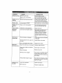
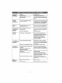
TROUBLE
Difficult
CAUSE
starting
CORRECTION
Defective spark plug
Replace defective plug
Water or dirt in fuel system
Use carburetor bowl drain to
flushand refill with fresh fuel
Blocked fuel line or low on fuel
Clean fuel line; check fuel suppry; add fresh gasoline (gasoline/oil mixture if 2-cyc}e engine)
Unit running on CHOKE
Move choke lever to OFF position
Water or dirt in fuel system
Use carburetor bowl drain to
flush and refill with fresh tuel
Loss of power
Excessive
vibration
Carburetor out of adjustment
Adjust carburetor
Units fails to
propel itself
Drive belt loose or damaged
Adjust auger drive belt: Replace
if damaged
Incorrect adjustment of auger control cable
Adjust traction drive cable
Worn or damaged friction wheel
Repair friction wheel
Auger drive bett loose or damaged
Replace auger drive belt
Auger control cable not adjusted
correctly
Adjust auger control cable
Shear bolt broken
Replace shear bolt
Discharge chute clogged
Stop engine immediately and disconnect spark plug wire. Clean
discharge chute and inside o_ au_
get housing
Foreign object lodged in at,,ger
Stop engine immediately and disconnect spark plug wire Remove
object from auger,
Engine runs
ratically
er-
Engine stalls
Engine runs
ratically;
or
er-
Unit fails to
discharge snow
Headlight does
not work
Loose parts; damaged impeller
Loose wire connection
!Stop engine immediately and
disconnect spark plug wire,
Tighten all bolts and make all
necessary repairs If vibration
continues, have the unit serviced by a Sears service repairman
Tighten connection
Bulb burned out
Replace headlight b_Jtb
25
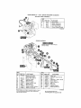
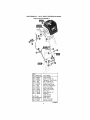
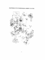
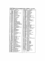
CRAFTSMAN
29"- 10H_P. SNOW THROWER 53&,882650
ELECTRIC START ASSEMBLY
REF
NOo
6
7
PART NO_
_
8
PARTNAME
6218
8216
Starter Motor ............
Screw, 1/4-20x 50
6217
62t9
7602 t 1
Screw, #6-32X2 50
Cord, Starter Motor
Owner's Manual Eng/Sp
319051B
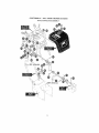
ENGINE ASSEMBLY
ENGINE MOUNTS TO REAR HOLES
ON THE FRAME
REFJ
NO.
PART NO.
t0
ENGINE
12
t3
31
33
34
41
43
44
331216
120638
3949
120638
578733
3949
120638
578733
5t
57e855
PART NAM E
Model 143 971003
(See Engine Pages}
Screw, 5/16-18Xl 50
Washer, Hvspttk
Belt Guide RH
Washer, Hvsptlk
Screw. 5/16-24X 625
Bell Guide RH
Washer, Hvsptlk
Screw, 5/t6-24X 625HHC
Washer, Crankshaft
Note: Always use original equipment
parts, Use ol
service/replacement
parts other lhan original parts
may void your warranly
26
REF,
NO., PARTNO,,
53
54
57
58
59
60
63
67
68
69
.....
57985_'
579861
579932
73840
586251
586253
585416
313826
120382
39573
PART NAME
Pulley Half
Ffatwasher 752X 9tX 02
Belt. V
Flatwasher
765X1 12X 06
Spacer Sleeve
Engine Pulley V4L
Belt, V 4L
Flalwasher
Washer, Regsptlk
Screw 3t8_24X1 00
319042G
All unnumbered
interchangeable
items are
with opposite
side
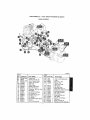
CRAFTSMAN
29" - 10H, P. SNOW THROWER 536,,882650
FRAME ASSEMBLY
340554F
REF.
!NO,
80
188
i90
91
106
108
109
1to
111
112
1t5
116
117
116
119
!20
121
122
PART NO.
340386-848
35497
583031_646
310169
340682
340373
340669
565781
996418
313843
41529
585470
585606
585446
73801
561540
760072
585609
PART
NAME
NO,
Frame Assy
Screw, 5116-t8X 50
Cover, Bottom Wheel
Screw, 114-20X 63
Cable Clip
Cable, Auger
Shield, Cable Guard
Bolt, 3/8-16Xt 25
Flatwasher 506x 75x 024
Idler Pulley
Nut, 3/8-16 Hxclrlkjam
Bolt. Brake Arm
Nut, 9/16-18 Jamctdk
Bolt_Brake Arm
Pin, Spring
Pad, Auger/Impeller Brake
Bracket
Nut, 1/2-20 Jamctrlk
PART NO,
t27 1483o6
128 _58336
129 1120385
133
I40
14t
142
t43
144
t45
t46
148
149
t60
16t
!62
27
1339017
1579872
1180077
]73795
1579665
{71038
1313854
/t80124
1313843
141529
[580772
1310t69
1120392
PART NAME
Nut, 114-20 Regb,exc_tflk
Pu{ley
Bolt. 375 x ,375
Washer, Fiat
,250 x 56 x 049
_dler Spring
Idler Arm Lever
Screw 5!16-I8X 75
Flatwasher 328Xt 25X 075
Bushing, idler Lever
Nut, 5!16-18 Hexnly
Idler Spring
Screw, 3/8-16X1 25
Idler Pulley
Nut 3/6-16 H×clrlkjam
Belt Cover
Screw. t/4-20X ,63
Flatwasher ,281X .63X,065
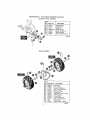
CRAFTSMAN
29"+ 10H°P+ SNOW THROWER 536°882650
DRIVE ASSEMBLY
+
313995 I
+ .......................
REF,
NO+ PART NO,
190
t91
192
t93
195
196
t98
210
211
215
216
2"f7
579941
313853
137185
313919
579937
11871
t502
583163-853
583208
583155
85501
71074
221
222
73811
580969
223
224
225
226
227
43846
58O97O
580961
580965
1084
228
t20380
REF,
PART NAME
ao_,
Lever Assy
Bearing Flange
Cotter Pin
229
230
23!
232
235
240
243
244
245
246
247
249
25O
255
256
257
270
27t
275
276
277
278
Spring, Return
Lever, Spring Traction
Screw 1/4+20X 63
Nut, 1/4-20 ReghexctrIk
Disc Assy
Grease Zerk
Hex Shaft
Trunion Bearing
Flat'washer
+53 XI.00X 063
Retex Ring
Ratwasher
+680XI 12X 060
Bali Bearing
Square Key. 18SQX,63LG
Pulley, V3L 6 50X 56
Wave Washer
Flatwasher
.28tXt O0X 063
Washer, Regspltck
28
PART NO,,
180020
334163
35497
120638
579858
579897
462
71074
337029
313883
11871
303008
579858
334163
35497
120638
334163
35497
583010
334163
35497
579867
PART NAME
Screw, 1/4-20X 75
Bearing and Retainer Assy
Screw 5/16+18X 50
Washer, Hvsptlk
Special Washer
Hex Assy #40+8TW
Retex Ring
Flatwasher 53 X100X 063
Trunion Bearing
Friction Wheel Assy
Screw, 114-20X 63
Nut 1/4-20 Hex Keps
Special Washer
Bearing and Retainer Assy
Screw 5/16+18X 50
Washer, Hvsptlk
Bearing and Retainer Assy
Screw, 5/16+!8X ,50
Jack Assy#41-36T&7T
Bearing and Retainer Assy
Screw, 5/16+18X ,50
Chain Roller #42 X 40P
CRAFTSMAN
29" - 10HoP_ SNOW THROWER 536882650
GEAR CASE ASSEMBLY
314014D
REF,
NO.
30t
303
304
305
306
3!0
311
312
3t3
314
315
PART NO.
896
895
910828
71100
330434
313872
1065
31387O
313871
584515
897
313861
PART NAME
Gear Case RH
Gear Case LH
Screw, 5/16-24X1 O0
Nut, 5It6-24
Screw, 5/t6-24XI
50
Pipe PIut
Oil Seat
Bearing Sleeve
Flatwasher
Auger Shaft
Gasket, Gear Box
Worm Gear
29
REF
NO.
PART NO.
316
320
321
322
323
324
326
327
330
340
73905
313914
583126
9346
313828
9346
5O795
313862
53731
585423-853
PART NAME
Woodruff Key#91
Ring, Quad
Bearing, Flange
Flatwasher 752X1 24X 093
Bearing, Roll
Flatwasher .752Xt 24X 093
Hi-Pro Key 606
Worm Gear
Bearing. Sleeve
lmpeIler Assy
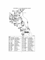
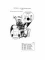
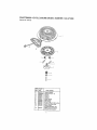
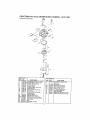
CRAFTSMAN 29" - 10H.P,, SNOW THROWER 536.882650
DISCHARGE CHUTE ASS EMBLY
REF°[PARTNO
NO. i
PART NAME
!580 904138-853
1582 578088
i584 71038
585 578o88
586 671t
587 171038
600 904137-853
501 58628o
602 120393
Upper Chute
Screw, 5/t6-t8X
,75
Nut. 5/t6-t8 Reghxctrlk
Screw. 5/16-18X 75
Plastic Washer
Nut, 5/16-t8 Reghxctrlk
Lower Chute
Bolt, 5/16-18Xt 00
Fla_vasher
.344X 69X.065
NuL 5/16-18 He×nyl
Chute Collar
Screw, 1/4-20X 75
Flatwasher
,281X 63X 065
NuL 1/4-20 Reghxctflk
Inner Ring Retainer
Outer Ring Retainer
Worm Gear
Worm Bracket
603
i606
i607
608
71038
585214-853
180020
120392
609 1502
610 337227
161t _585t93
612 585196
613 585195
340892D-1
3O
CRAFTSMAN
29" - 10H.P. SNOW THROWER
AUGER HOtJSING ASSEMB,L¥
536,,882650
339974 !
PART NO.
i583146
=7137t
i7t074
274654
334514
i582960
!43846
i180077
;710026
,339512-848
'336657
i760073
710200
t499
340353
t499
586224
120382
585247
71003
t499
I499
REF,
NO.
PART NAME
Pulley, V4L 8 40 OD
Square Key 18SQX 88LG
Ftatwasher
.53 X 1O0X 063
Nut, 112-20 Reghxctrlk
Spacer, Sleeve
Ball Bearing Retainer
Bal! Bearing
Screw, 5/16-18X. 75
Nut, 5/!6-18 Reghex
Housing Assy
Plate, Clutch Arm
Idler Brackel
Sh. Bolt, 3/8-16
Nut. 3/8-16
Bracket. Cable Mounting
Nut. 3/8-16 Reghxctrlk
Stud, Brake Arm
Washer, Regsptlk
Mounting Bracke!
Screw, 3/8-t6X .75
Nut, 3/8-16 Reghxctrlk
Nut, 3/84 6 Reghxctrik
509
5t0
511
5t4
520
521
522
523
524
525
526
527
540
541
542
543
544
31
PART NO,
PART NAME
760040
Plug
563043-853 i Scraper Blade
Bolt, 5/I6-18X 75
70993
710026
Nut. 5/t6-16 Hxwdllik Whiz
584469-853
Auger Assy RH
584468-853
Auger Assy LH
9524
Screw, 1/4-2OX1 75
3943
Spacer Sleeve
1502
Nut, 1,'4-20 Reghxctrlk
313873
Auger Shaft Bearing
73755
Flatwasher
1 005X1 3tX.035
35498
Screw, 5/16q8X
75
309016°853
Height Adj Skid
70993
Bolt. 5/16-t8X .75
120393
Ftatwasher
.344X 69X 065
120638
Washer, Hvsptlk
Nut, 5t16-18 Reghex
[120376
CRAFTSMAN
29" - 10H.P_ SNOW THROWER 536,.882550
HEADLIGHT PANEL ASSEMBLY
REF.
NO. PART NO.
621
624
625
626
627
628
581575
331712
57444
578304-853
301542
308283
308282
629
PART
NAME
Headlight Assy
Wire Harness
Cable Tie
Retaining Ring
Screw, 10-24Xl .00
Rubber Washer
Spring 296 tDX 93 LG
338778A
WHEEL ASSEMBLY
REF
NO. I PART NO
650
552
653
654
655
656
67t
673
675
676
677
_78
379
5830t7
583007
73839
t5o2
581730
583o13
73840
585591
584633
577015
1502
239
73842
PART NAME
Axle Shaft
Hub Sprocket
Screw, 1/4_20X2 25
Nut, ti4-20 Reghxctrik
Bearing, Flange
Roller Chain
Flatwasher 765X1 12XO6
Wheel Bushing
Tire and Rim
Screw t/4-20X t. 75
Nut, 1t4-20 Reghxctdk
Retex Ring
KIik Pin .25 X 1.38 DtA
3t8542E
32
CRAFTSMAN
REF,, KI
29"- 10H.Po SNOW THROWER 536382650
HANDLE ASSEM BLY
731
€
,?.
REF_I
NO.
72O
721
724
725
726
727
728
729
730
731
732
733
734
735
736
737
738
739
REF..
PART NO.
58 t736-853
581738-853
71OO7
! 20394
120382
1499
7289
578328
581761-853
581758-853
581766
300311
3535
4049
579057
180016
t502
84t7
NO.
PART NAME
74O
741
742
743
744
i745
746
75O
751
752
753
754
756
760
761
762
Handle, Upper LH
Handle, Upper RH
Screw. 3!8-16X2 O0
Ftatwasher
.406X 8IX 065
Washer, Regsptlk
Nut, 3t8q 6 reghxctrlk
Plastic Stop
Grip, Handle
Handle Assy, LH
Handte Assy, RH
Rod, Clutch Handle
E Ring
Push-on Nut
Bumper
Cam Bracket
Screw, 1/4-20X 50
Nut, I/4-20
Cam Lock,
763
764
33
PART.NO ....
PART NAME
584673
Pin. Spring Pivot
73664
Push-on Nut 3/8"
579257
Cable. Clutch Control
579869
Tension Spring
t673
Spring. Auger C{utch
t502
NuL 114-20 Reghxctrlk
308146
Boot, Clutch Spring
5543-853
Lower Handle
35497
Screw, 5/16-!8X
50
120638
Washer, Hvsptlk
1498
Nut. 5/16-18 Reghxctrlk
35498
Screw, 5116-18X °75
71007
Screw, 3/8-t6X2 00
578330-853
Panel Assy
302900
Screw, 5tI6-I8X1
75
120393
Flatwasher
.344X 69X 065
120638
Washer. Hvsptlk
120376
Nut, 5/16-18 Reghex
CRAFTSMAN
29" - 10HOP. SNOW THROWER 536,882650
HANDLE ASSEMBLY
PART NO.
770
772
774
780
781
782
783
784
786
790
791
792
793
794
795
796
811
8_2
339966
3003o3
579440
578144-853
122168
313842
120394
71046
578292
121222
120393
308696
120368
6352
120638
313841
579944
337436
1499
PART NAME
Console
Screw. 25X 75X.51
Screw, t/4-20X 50
Gear Se{ector Bracket
Screw. 3/8-t6Xt 75
Spring
Ftatwasher 406X B1X 065
Nut. 3/8-16 Hexnyl
Knob. 1,50 DIA
Cotter Pin 090 DIAX _75LG
Flatwasher 344X 69X 065
Shilt Rod
Nut, 5/I6-24 Reghex
Adaptor, Rod
Washer, Hvspt}k 328X 60X 09
Steel Ball Joint
Bearing Flange
Red, Assy Yoke _Pane{'_
Nut, 3/8-16 Reghxctrtk
340090E-2
34
CRAFTSMAN
29"+
10H.P+ SNOW
THROWER
536+882650
R EMOTE CHUTE ASSEMBLY
REE
NO.
PART NO.
PART NAME
965
967
968
969
970
971
972
973
974
975
981
990
991
903519
56934
120393
1502
180073
904173
1498
35258
71055
340705
9O4135
122168
120394
Spr+ng, Tension
Screw. 1/4_20X1 O0
Flatwasher+ 344x 69x 065
992
993
995
996
4051
578659-853
578293
71046
Nut+ 1/4+20 Hexnyl
Screw, 5/I6+18X 75
Bracket. Cab}e Chute
Nut+ 5/16+18 Reghxctrlk
Screw, I0+24X 38
Nut, #t0-24 Hexn]lk
Cabte. Chute Control
Wire. Form
Screw, 3/8+16X1 75
Flatwasher
.406X 81X 065
Spring Washer
Chuter Lever
Knob, I5 Diameter
Nut, 3/8_16 Hxn+y
340892D-2
35
CRAFTSMAN 29" . 10H.p., SNOW THROWER 536.882650
CHUTE CONTROL ROD ASSEMBLY
EY#864
36
CRAFTSMAN
29" - 1OH,P,, SNOW THROWER 536.882650
CHUTE CONTROL ROD ASSEMBLY
REF.
NO,
PART NO.
÷
850
851
PART NAME
....................
578295
120394
!852
_853
854
855
856
857
858
859
121222
578051
578O43
1795
73664
578044-853
180077
120393
860
861
862
864
71038
760078
30289
760065_853
865
867
868
872
310169
339560
55O23
578063
i873
i874
1875
578309
578060
579493
Rod. Assy Upper Chute
Fla_asher
408X 81X 065
Cotter Pin
Cover. Chule Crank
Handle
Retainer Cap 3/8
Nut. Push-on 3/8"
Bracket, Console
Screw. 5/16-t8X 75
F_atwasher
.344X 69X.085
Nut, 5116-18 Hexnyl
Rod, Mid-Chute Assy
Wave Washer
Bracket. Lower Chute
Control
Screw. t/4-20X 63
Rod ,Lower Chute Assy
Trim 77 5"
Block, Universal Pivot
Clevis Pin
Pin. Universal Joint
Cotter Pin
340866F
37
CRAFTSMAN
29"+ 10H, P+SNOW THROWER 536+882650
DECALS
'_ Symbot denotes top of decal application,
IOM AUGE
HOUSING REAR
VIEW FROM AUGER
FRAME REAR
34o893A
REF,
NO. PART NO.
822
823
824
825
826
827
828
38
402905
70141
313892
302922
402904
4O29O7
308768
PART NAME
Decal,
Decal
Decal.
Decal,
Decal.
Decal,
Decal
12" ImpeJler
Danger Foot
Danger Chute
Danger
Craftsman
10/29 ES
Danger Chute
CRAFTSMAN
4-CYCLE
ENGINE MODEL NUMBER:
143.971003
I
I
I
I
1
I
!
I
I
I
370C
39
CRAFTSMAN
Re/.#
Part No,
t
35371
2
27552
3
650820
4
30968
5
30969
t5
30699C
15A
30700
1SB 650494
16
33454
t7
29918
18
651028
19
34663
20
35319
25
36460
25
650561
28
30322
30
36245
35
29826
36
29918
37
29216
38
29542
40
35776
40
34777
40
34778
41
34773
41
34774
41
34775
42
35779
42
35780
42
35781
43
35772
45
36896
147
651033
48
34034
49
35895
50
35375
60
33273A
61
34126
62
650760
63
28545
65
650128
69
35262A
70
35376
71
35377
72
27542
75
35319
80
31845
81
30590A
82
35378
83
30588A
84
29193
86
650833
87
650832
89
32589
90
611193
92
650880
93
650881
100
35153
101
610118
t02
650872
103
551007
110
35253
t10A+35305
119
36451
120
35449
125
27878A
125
27880A
126
34635
t26
34036
127
550691
128
650690
t29
650727
130
6021A
131
650694A
131A 550713
t35
35395
139
33369
140
550835
4-CYCLE
ENGINE MODEL NUMBER:
Description
Cy+inder
(tnci_I20oiZ)
Ref,#
Part No,
!14g
278_2
149A 35862
150
27881
151
32581
169
27896A
'170
28423
t71
28424
172
28425
_173
35350
1174
650128
i178
29752
i182
30088A
+183
34587A
t54
33253
185
33877
i186
34667
11858 36552
200
34677
!203
31342
!204
651029
!206
610973
207
33878
209
650821
i215
35440
i219
34586
i220
35438
222
28820
223
650378
224
27915A
260
35447A
1261
650788
262
297478
264A 650802
265
33272B
_275
35056
:275
31588
277
651002
+281
33013
282
650760
i285
35985B
1287
29752
+290
30705
292
26460
298
550665
_300
34156A
30!
35355
305
35554
1307
35499
1308
35540
310
36205
314
650873
3t5
6111_1
323
611118
325
29443
328
35593
329
610973
335
35057A
336
650765
338
28942
340
34154
341
34155
342
650551
350
570682
351
32180C
355
590574
364
33377
365
650767
370A 36261
370C 36501
370D135077
370t 35878
380
640054
390
590733
396
33329D
Dowel Pin
Screw, 1/4-20xl/2'
Oil Drain Extension
Extension Cap
Governor Rod (Inc115A & 158)
Governer Yoke
Screw 6.40 x 5t16"
Governor Lever
Governor Lever C_amp
Screw Torx T- 15, 8+32x3/8
Speed Control Spring
Oil Sea+
Blower Housing Baffle
Screw 1/4-20x5/8"
Loocknut 8-32
Crankshaft
Screw t 0-32×3/4 +
Lockwasher
Locknut t 0+32
Retaining Ring
Piston.Pm.&Rmg Set(Std)
Pis{on.Pm,&Ring
Set( 010 _)
P+ston,Pin+&Ring Set( 020 +)
Pislon&Pin Assy{Std(incL43)
Piston&Pin Assy( 010" OS)(}ncl 43
PJslon&Pin Assy( 020" OS(_nd 43
Ring Set (Std)
Ring Set ( 0t0 +OS)
Ring Sol ( 020 _OSI
Piston Pin ReIa}nin!l Ring
Connecting Rod As ;y(inc147&49)
Connecting Rod Bc I[
Valve Lilter
Oil D}pper
Camshaft (_ CR)
Blower Hsin{ Extension
Grommet Mt ) Bracket
Screw 8-32x _/8+
Grommet
Screw t0-24xl/2"
Cylinder Cover Gasket
Cylinder Cover (Incl 71.75,&80)
Crankshaft Bush+ng
OilDrain Plug
OilSeal
Governor Shall
Washer
Governor Gear Assy (fncI 81 )
Governor Spool
Retaining Ring
Screw. 1/4+20xl-3/t6"
Screw t14-20x1-11/t6"
Flywheel Key
Ftywhee| (wiring gear)
Lock Washer
Flywheel Nut
SoI+d Sla_e Ignition
Spark Plug Cover
So!{d State Mt_n9 Stud
Screw Torx T+15 10-24x15/16
Ground Wire
Ground Wire Assy.
Cy+inder Head Gaske!
Cylinder Head
Exhaust VaNe (std)(Incl t51)
Exhaust Valve(I/32" OS)(incl t51)
intake Valve (std)(Incl. 15t)
lnlake Valve (U32 +OS)(Inc1151)
Washer
Beltevilte Washer
screw, 5/16-18xi .3t4"
Screw 5/16+.18xl - 1/24
Screw. 5/I6..18 x2 _
Screw 5/16,,,18 _ 5t8 _
Resistor Spark Plug(R Jl gLM)
Governor Gear Bracket
Screw 10-24xl/2 "
400
40
36452
143.971003
Description
Valve spring cap
Vabe Spring Cap
Valve Spring
Valve Spring Keeper
Valve Cover Gasket
Breather Body
B+eather Element
Valve Cove_
Breather Tube
Screw 10.24 x 1/2 '+
Nut & Lock Washer t14+28"
Screw. t/4-28x1"
Choke Bracket
Carburetor To Intake Pine Gskt
Intake Pipe
Governor Link
Choke Spring
Control Bkt (Inct, 203-204)
Compression Spring
Screw, TorxTo 10.5-40x7/16"
Terminal
Thre_;tIe
Link
Screw 10-32 x 1/2 _
Control Knob
Choke Rod
Choke Knob
Screw 10,32 x 1/2"
Screw Torx T-40 5/16-18x1-1/8"
Intake Pipe Gasket
Btower Housing
Screw 5/15-18x3/4"
Screw Torx T-40 5116+24x21/32"
Screw, 1/4-20x518"
Cylinder Head Cover(Black)
Multler
Locking Plate
Screw 5116+18x4-3116 _
Starlet Bubble Cover
Screw 8-32x3/8"
Starlet Cup
Nut & Lock washer 1t4-28
Fuel Line
Fuel Line Clamp
Screw t/4+15 X 3/4 +
Fuel Tank (Incl 292 & 301)
Fuel Cap
Oil Fitl Tube
0 Ring
ill Tube Clip
Dipstick
Screw I/4+20 x 3/4"
Alternator Coil(18 Watt)(lncl
Terminal
Wire Clip
Ignilion Key
Termina[
Carburetor Cover
Screw 10-32x 1/2"
Screw t0.32x3/8"
FueI Tank Bracket
Fuel Tank Bracket
Screw tl4-20x518"
Primer Bulb
Primer Line
S'iarler Handle(Mitten Grip)
Carburelor Cover Bracket
Screw 8..32x27/64"
Lubrica[on Decal
Pdmer Decal
Instruction Decal
Warning Decal
Carburelor (Incl 184)
Rewind Starter
Electric Starlet Motor Kit
(Optional)
Gasket Set
323)
CRAFTSMAN
Starter
No
4-CYCLE
ENGINE MODEL NUMBER:
590733
NO.
1!
I 2
I 3
!590599A
159o6oo
159O696
14
ISgOSOl
I5
I §
I 7
I 8
I It
1590697
1590698
1590699
1590709
1590734
12
_
t590535
590574
PART NAME
Rewind Starter
Spring Pin (Incl 4)
Washer
Retainer
Washer
Brake Spring
Starter Dog
Dog Spring
Pulley & Rewind Sprg Assy
Starter Housing Assy
Starter Rope
(Length 98"x9/64" die)
Mitten Grip Handle(not
included with starter)
143.97'1003
CRAFTSMAN
Carburetor
4-CYCLE
ENGINE MODEL NUMBER:
No, 640054
__
__i_\ 0
2
_ _I_,'< 2o
C_-..,
20a
REF,
_NO.
0
I
2
6
7
I0
14
15
16
17
18
20
20A
25
27
28
29
143.971003
"15
J
.)
1
PART
NO.
PART NAME
640054
Carburetor (inci' t84 on engine)
631776A Throttle Shall & Lever Ass'y
631970
Throttle Return Spring
631778
Throlter Shutler
650506
Shutter Screw
632112
Choke Shaft & Lever Assy
632174
Choke Shutter
630735
Choke Positioning Spring
632164
Fuel Fitting
650417
Throttle Crack Screw/Idle
Speed Screw
630766
Tension Spring
640016
tdte Restdctor Screw
640053
{die Restriclor Screw Cap
63195_!
Float Bowl Assy (Inc132&33)
631024
Float Shaft
632019
lea[
631028
:teat Bowl "O" Ring
42
REF_
PART
!NO.
30
NO,
631021
31
32
33
36
37
14o
44
47
48
631022
_7136A
_7554
640055
632547
640055
27t_0
630748
631027
PART NAME
tnlet Needle. Seat & Clip
(Incl 31}
Spring Clip
Bowl Drain Assembly
Drain Plunger Gasket
Ma{n Nozzle Tube
"O" Ring, Nozzle Tube
High Speed Bowl Nut
Bowl Nut Washer
Welch Plug, idle Mixture Well
Welch Plug. Atmospheric Vent
REMOVEDORA
DE NIEVE (Arranque
el_ctrico
Tabla of Contenidos
43
Garantia
43
Reglas de Seguridad
43-45
Contenido del paquete con articulos 46
Montaje
47_51
Operacion
51-56
Mantenimento
57-60
opcional)
Servicio y Ajustes
Almacenamiento
Solucion de Problemas
Parles de Repuesto
Partes de Motor
Spanish(Espa#,ol)
Orden de PaRes Servicio
GARANT1A LIMITADA DE DOS AltOS SOBRE LA REMOVEDORA
CRAFTSMAN
60-67
68
69
26.38
39*42
43-69
Contratapa
DE NIEVE
Durante dos a_os a partir de la fecha de compra, cuando esta Removedora de nieve
Craitsman sea martenida, tubricada y afinada de acuerdo con las instrucciones en el
manual def propietario, SEARS reparar& sin recargo alguno, cualquier defecto en
materiales y mano de obra
Siesta Removedora de nieve Craftsman se usa para prop6sitos comerciales o de
arrendamiento, esta garantia es v_lida durante 90 dlas a partir de la fecha de compra
Esta garamtia no cubre lo siguiente:
• Etementos fungibtes los cuales se gastan durante el uso normal, tales como buijias,
correas de transmisi6n y claavijas de seguro pot esfuerzo cortante
• Reparaciones necesarias debido at abuso o negtigencia del operador, incluyendo
cigOeSales doblados y la falta de mantenimiento del equipo de acuerdo con ias
instrucciones contenidas en el manual del propietario
EL SERVICIO DE GARANTIA SE PUEDE OBTENER AL DEVOLVER LA
REMOVEDORA DE NIEVE CRAFTSMAN AL CENTRO/DEPARTAMENTO
DE
SERVICIO SEARS MAS CERCANO EN LOS ESTADOS UNIDOS ESTA GARANTIA
ES VALIDA SOLO CUANDO ESTE PRODUCTO SEA USADO EN LOS ESTADOS
UNIDOS
Esta garantia le otorga derechos legales especificos, y asimismo es posible que
tenga otros derechos los cuales varian de estado a estado
Sears, Roebuck and Co, D817WA, Hoffman Estates, fL 60179
,4,,
Busque este simbolo para deslacar precauciones
Esto significa--_ATENClON!!!
Este!!! U seguridad
PRECAUCION: Siempre desconec|e el
alambre de la bujia y coloquelo donde no
jaga contactao con bujia para evitar un
arranque accidental al montar, transportar,
ajustar o efectuar reparaciones
IMPORTANTE: Los estandares de
seguridad requieren la presencia det
operador en los controles para minimizar el
rlesgo de heridas Su remeverdora de nieve
esta equipada con dichos controles No
intente pasa[ por alto la funcion det control
de preseenc_a del operador bajo ninguna
circunstancia
CAPAClTACION
-
Lea et manua! del operador
cuidadosamente
Famitiadcese
completamente con los controles y el
uso apropiado de la removedora de
nieve Sepa c6mo detener la
removedora de nieve y desenganchar
los controles r&pidamente
de seguridad ]mportantes
esta de por medio
.
Nunca permita a niSos operar la
removedora de nieve y mant6ngalos
luera del alcance de la misma mientras
se encuentra en operaci6n Nunca
permita que adultos operen la
removedora de nieve sin inslrucci6n
apropiad& No Iteve pasajeros
*
Mantenga el &rea tibre de personas,
especialmente niSos pequeSos y
mascolas
Tenga precauci6n a fin de evitar
deslizamien'ios o caidas, especialmente_
al operar la removedora de nieve en
retroceso
PREPARAClON
-
43
Inspeccione completamente el &tea
donde se usar& la removedora de nieve
y retire todas las esteras, trineos,
tableros, alambres, y otros objelos
extraAos
•
,
(a)
(b)
(c)
(d)
(e)
(f)
•
•
•
,
OPERACION
Desenganche todos los embragues y
cambie a neutro antes de arrancar el
motor.
•
No opere la removedora de nieve sin
vestir las prendas de inviemo
adecuadaspara ambientes exteriores.
Vista calzado que mejore su
estabilidad en superficies lisas
Maneje el combustible con cuidado; es
altamente inflamabte
Use un contenedor para combustibIe
aprobado.
Nunca retire la tapadera del tanque de
combtible o aSada combustible a un
motor enmarchao a un motor
caliente
Llene el tanque para combustible al
aire libre, con cuidadoextremo.
Nunca llene el tanque en ambientes
interiores.
Coloque nuevamente la tapadera
del tanque paracombustible de
manera segura y timpie el combustible derramado
Nunca a[macene combustible o ]a
removedora de nieve con combustible
en el tanque dentro de un edificio
donde los vapores pudiesen entrar en
contacto con una llama desprolegida o
una chispa.
Verifique las existencias de combustible antes de cada uso, permitiendo
espacio para expansiSn puesto que
el calor del motor y/o el sol pueden
causar la expansion det combustible,,
Use cables de extensi6n y
recept&culos de la manera
especificada por et fabricante para
todas las removedoras de nieve con
motores accionados por energia
el_ctrica o motores de arranque
et_ctrico
Ajuste ta altura de la removedora de
nieve para pasar sobre superficies de
grava o piedra triturada
Jam&s intente efectuar ningun ajuste
mientras el motor se encuentra en
marcha (excepto cuando el fabricante
Io recomiende asi especificamente).
Permita que el motor y la removedera
de nieve se ajusten alas temperaturas
exteriores antes de comenzar a retirar
la nieve.
-
,
•
•
•
•
Siernpre use galas de seguridad o
protectores para los ojos durante la
operaciSn o mientras se efect0a un
ajuste o reparaciSn para proteger sus
ojos de objetos extraSos que pudiesen
set lanzados pot la removedora de
nieve
•
,14
No coloque las manos o los pies cerca
o bajo piezas rotativas. Mant6ngase a
distancia de ]a abertura para descarga
todo el tiempo
No opere esta m_.quina si est#,tomando
drogas u otras medicinas que pudiera
causar somnolencia o que pudieran
a_ectar su habitidad para operar esta
m&quina
No opere esta m_quina si su estado
emocional o fisico no le permite
operaria con seguridad
Tenga precauciSn extrema al operar
sobre o al cruzar caminos, aceras, o
calles de grava Mant_ngase alerta en
caso de peligros ocullos o tr&fico
Despu_s de golpear un objeto extraSo,
pare el motor, retire el alambre de la
bujia, desconecte et cable en motores
etectricos, inspeccione complelamente
_a removedora de nieve a tin de
encontrar cualquier da5o, y reparar
dicho da_o antes de arrancar y operar
la removedora de nieve nuevamente
En el caso de que la removedera de
nieve comience a vibrar fuera de Io normal, pare el motor y revise la m_quina
inmediatamente para encontrar la
causa Generalmenle, Ia vibraciSn es
una advertencia de problemas.
Pare el motor dondequiera que deje la
posici6n de operaci6n, antes de
desobstruir el alojamiento det barreno/
propulsor o guia de descarga, y cuando
efectt)e cualesquiera reparaciones,
ajustes, o inspecclones
At limtoiar, reparar, o inspeccionar la
m_qutna asegurese de que el barreno!
propulsor y toda parte m6vil se hayan
detenido. Desconecte e! alambre de la
bujia y mant_ngato alejado de la bujta
para evitar un arranque accidental
No #onga en marcha el motor en
ambientes interiores, excepto a!
arrancar el motor y para transportar la
removedora de nieve hacia adentro o
hacia afuera del edificio Abra las
puertas exteriores; el humo del escape
es peligroso (contiene MONOXIDO DE
CARBONO, un GAS INODORO y
LETAL).
No limpie nieve perpendicutarmente a
la direcciSn de pendientes. Tenga
precauci6n al cambiar de direcci6n en
pendientes No intente limpiar
pendientes pronunciadas
Nunca opere la removedora de nieve
sin que los resguardos, placas u otros
dispositivos de seguridad se
encuentren en su lugar.
•
Nunca opere la removedora de nieve
cerca de recintos de vidrio,
automSviles, huecos de ventanas,
sitios de cargaldescarga y similares
sin el aj_.Jsteapropiado de/_,ngu]o de
descarga de la nieve Mantenga niSos
y mascotas aleiado&
•
No sobrecargue la capacidad de la
m&quina al intentar limpiar nieve a una
velocidad demasiado r&pida
•
Nunca opere la removedora de nieve a
altas velocidades de transpode sobre
superficies resbalosas Mire hacia atr&s
y tenga cuidado al retroceder
•
Nunca descargue directamente sobre
espectadores ni permita a nadie frente
a la removedora de nieve
•
Desenganche la fuerza motriz at
barreno!propulsor cuando la
removedora de nieve sea transportada
o est6 fuera de uso
•
Utilice t)nicamente aditamentos y
accesorios aprobados por el fabricante
de ta removedora de nleve (tales como
cadenas antiderrapantes para las
Ilantas, juegos de arranque el6ctrico,
etc )
•
Nunca opere la removedora de nieve
sin buena visibilidad o iluminaci6n,
Siempre est6 seguro de su estabitidad,
y mantenga un agarre firme de las
manijas Camine; jam&s corra
MANTENIMIENTO
Y
ALMACENAMIENTO
°
.
•
•
•
Revise los pernos de seguro por
esfuerzo cortante y otros pernos que
frecuentemente no est&n aprelados
adecuadamente para asegurarse de
que ia removedora de nieve est& en
condiciones seguras de trabaio.
Nunca almacene la removedora de
nieve con combustible en el tanque
para combustible dentro de un edificio
en el cual se encuentran presentes
fuentes de ignici6n tales como agua
caliente y calentadores de espacio,
secadoras de ropa, y similares Permita
que el motor se enfrie antes de
almacenarlo en cualquier recinto
Siempre refi_rase a tas instrucciones
del manua! del operador para consutta
de los detalles importantes si ta
removedora de nieve serA almacenada
durante un periodo de tiempo
prolongado
Mantenga o cotoque de nuevo las
etiquetas de seguridad e instrucciones,
de acuerdo ale que sea necesario
Mantenga la removedora de nieve en
marcha unos cuantos minutos despu@s
45
de tirar la nieve para evitar el
congelamiento det barreno!propulsor
z_ ADVERTENClA: Esta removedora de
nieve se usa para aceras, caminos de
entrada, y otras superficies de terreno
lanas. Se debe tener mucha
RECAUCION al utilizarla en superficies
con pendiente pronunciada NO USAR LA
REMOVEDORA DE NIEVE SOBRE
SUPERFICIES POR ENCIMA DEL NIVEL
DEL TERRENO, tales como techos de
residencias, cocheras, porches u otras de
tales estructuras o edificios
Z_ ADVERTENCIA: Las emanaciones de
escape producidas por este motor
contienen quimicos reconocidos pot et
Estado de California como carcinogenos,
tambi_n pueden produeir defectos en los
reciL_nnacidos o causar otros daSos al
sistema reproductivo
_:..,i_-,_-_:i,i_:
_''''
!t
Contenido de la bolsa con las partes, mostradas
indique io contrario.
del tama6o real a menos se
i _ Manual dei Propietario
2 - Bolsa
2 -Tuercas de Seguridad de Repueste (I/4-20)
2 - Pemo Cabeza Hexagonal
1 - Tuercas Hexagonales
2 * Arandela Plana de
5/!6 de Pu{g
de 5/16 de Pulg
©D
2 - Espaciadores
de Repuestos
2 - Arandeta de Freno
de 5/16 do Pulg
2 - Pernos de Seguro per Esfuerza cortante de
Repuesto (1/4-2Oxl _3!4 Putgadas)
1 - Arandela Plana de
11/32 Pulg
1 - Cuerda det Arrancader EI6cldco
_
5!16-18x2 O0 Pulg
1 * C_aviia hendida
iiilIIiiilIiiiiIIIiillli"J'llllllililllllllllll
IIIIIIIIIIiIIIIIIIIiIi
1_ Ligaduras para cable
Parles empaquetadas en forma separada en ia caja de carton (no se
muestran del tamano real)
2 _ Ltaves de lgnici6n (Adjunlas al Motor
1 - Envase de Aceite 5W30
en Bolsa PI,Sstica)
I - Varilla de medio arranque
I - Varilta de control de velocidad
46
Cuando se hace referencia a los lados
derecho e izquierdo de la removedora de
nieve, es en relaci6n al operador de la
unidad ubicado frente a la manija de
direcci6n
Z_
PRECAUCION:
Use siempre
gafas de seguriclad o protectores para los
oios mientras opere la removedora de
nteve,
HERRAMIENTAS
REQUERIDAS
PARA EL MONTAJE
1-Cuchitlo (para cortar la caja y las amarras
pl&sticas)
2-Llaves tuercas de !/2 pulgada (o Ilaves
ajustabfes)
2-Llaves de tuercas 9/16 pulgada (o llaves
ajustaMes)
2-Llaves de tuercas 3/4 pulgada (o Ilaves
ajustables)
1-Tenazas o desatornillador (para extender
fa chaveta de dos paras)
1-Cinta o regla para medir
PARA RETIRAR LA REMOVEDORA
DE NtEVE DE LA CAJA
(yea la segundo
figura a la derecho)
• Encuentre y remueva el envase de aceile
de 5W30 que se encuentra en la parle
trasera derecha, inserto de la caja de
cad6n,
, Saque de fa caja et entabliilado protector
de arriba,
• Corte y descarte todas la amarras
pl&sticas que sujetan el conjunto del
cig6eSal al entablillado, y coloque et
conjunto a un lado descarte igualmente
et entabli!lado,
La figura abajo mueslra la removedora de
nieve lista para su env{o.,
• Corte las cuatro esquinas de la caia de
cart6n desde la parte superior a [a inferior
y lienda los paneles planes
• CoNe y deseche las ligaduras de pl_stico
y las bolsas que aseguran los barrenos y
los ejes de la rueda a la paleta
COMO
MONTAR
EL CANAL
DE NIEVE
• Remueva los pernos pedador de la parte
trasera, yea la figura a continuaci6n,,
La figura abajo muestra la removedora
nieve compfetamente
ensamblada
Perno
de
Patanca de!
Pa}anca de
Palanca de
Desviador del
Cambios
Propulsion
ga
Conjunto
Propulsion
del Barreno
Cable del
Embrague
e_a!
• Incline el canal hacia atr&s a la posici6n
de operaci6n, Vea la figura a
continuaci6n
de! Canal
_a
Tuercas de
Monlaje
de apoyo
para ajusle de la attura
47
- Gamble et perno portador
- Apriete el perno portador en forma
segura
• Remueva y deseche el material de
empaque que se usa para proteger el
canal de nieve
• lnstale los articulos de ferreter[a que
vienen en la bolsa con las partes
(tornillos, arandelas planas, arandelas de
seguridad, y tuercas de seguridad) en los
agujeros infer!ores.
• Apriete los cuatro pernos.
• Vuetva a co!acar las tapas protectoras en
los tornillos en los aguieros super!ores
PosiciSn
Operaci6n
CONEXION
DE LA LUZ DELANTERA
• Conecte los terminales dei arn_s de
cables al conjunto de la luz delantera
ubicado debajo de[ panel de control, tal
como se muestra en la figura a
continuacibn
Cabte de
Terminal del
faro
arn_s de cables
delantero
Perno
PARA INSTALAR
SUPERIOR
LA MANILLA
o Vorte y deseche las !igaduras de pi&stico
que aseguran los cables del embrague a
Ia manija inferior AMISO: Coloque los
cables ejos de la cubierta del motor..
• Remueva los pernos que aseguran los
mangos supedores a ios inferiores..(Vea
la figura siguiente ) AVlSO: Deseche la
arandela bfanca de pI&stico, que se usa
para el envio en ei lado derecho
AVISO: A no set que cuente con la ayuda
de otra persona, puede resultar m&s f_,cil
instalar un lado del mango a Ia vez.
AVISO: Aseg0rese que !os cables no se
han quedado agarrados entre el mango su
per!or y el inferior.
* Remueva et conjunto del mango superior
y r6telo a la posici6n de operaciSn Et
mango superior debe estar en e! exterior
del mango inferior
* Vuelva a colocar los pernos, ta arandeIa
plana, la arande!a de seguridad y las
tuercas hexagonales que se removieron
anteriormente en los agujeros supedores
No los apriete
Terminal
del
de cables
Majija
Ligadura de I:
Inferior
, Ate el cable del faro delantero aias
manijas superior e inferior con las
ligaduras de pt&sfico par cabtes provistas
en la botsa de piezas introduciendo los
AVISO: Un lado de ]a ligadura de pt&stico
tiene pequeSas muescas sobre s{, mien_ras
que ei otro lado es liso if:t !ado con
muescas deber& estar en el lado interior del
bucIe que se forma cuando se juntan los
extremos
Superior
CONEXION
MaiiJa
Remueva y
Tuerca
hexagena]
3/8 pu{g
Arandela /
de treno de
3!8 de
pulg
Vuelva
Arandela
Plana de
t_
REMOTO
• Pase e_accesorio "Z" a tray,s det
agujero en el puntal del canal remoto, tal
como se muestra ei !a figura sigueinte
• Meta a presiSn el cable de control del
cana! remoto dentro del puntal del canal
remoto, yea figura sigueinte
• Conecte el accesorio "Z" en el puntal de
control de! canal remoto, tal corn se
muestra en la figura sigueinte
3/8 de
pulg
"_'_-,
DEL CANAL
• Empuje la palanca de control del canal a
la posici6n de" deflector del canal arriba"
Pemo 3/8 pulg
X 2 pulg
48
Puntal de\
control def\
canal
remolo
Accesorio
"Z"
Ponga la horquilla extreme abierto della
vadlfa de medio arranque alrededor de la
junta universal en ia varilla de arranque
superior, lnserle el pasador de horquilla
a tray,s del conjunto y aseg0relo con la
ctavija hendida Separe los extremes de
la clavija hendida pare asegurada en su
lugar. Vea la figure siguien_,e
Puntal del canal
remolo
_lecontrol
de! canal remote
Varilla de
, Empuje la palanca de control del canal
remote ala posici6n de "deflector del
de
arranque
medio
_ue
superio
canal abajo" i,
. Corte la amarra en el deflector del canal,
tal come se muestra en la figura a
continuaci6n
. Code la amarra que asegura la varilla del
arranque inferior al puntal de la varilla del
canal
Amarra
• Ponga la horquilla de la varilla de inferior
arranque alrededor de la junta universal
en la varilla de arranque medio..
AVlSO: Si esto remueve la junta universal
y e_pasador de _sta, phngala dentro de la
horqui]la de la varilla de arranque superior,
alineando losagujeros grandes. Inserte el
pasador de la junta universal.
deflector del
canal
C()MO INSTALAR
LA VARILLA
DE
MEDIO ARRANQUE
(que se dej6 a un
lade anteriormente)
Pasador de la junta
_..
Universal
Extreme _<'--..__/.Junla
Universal
inferior de
_.<'_=_..,_""_k'k_.
• Cuidadosamente, remueva la clavija
hendida y el pasador de horquilia de ta
junta universal en la varilta de arranque
superior tal come se muestra en ]a figure
a continuaciSn
AVISO: Si esto remueve la junta universal
y el pasador de _sta, p6ngala dentro de la
horquilta de la varilla de arranque superior,
alineando los agujeros grandes lnserte el
pasader de la junta universal.
Pasador
de
Junta
• Oeslice la junta en la variila de medio
arranque dentro de la horquilla de la
varilla de arranque inferior. Inserte el
pasador de horquilla a travOs del
conjunto y aseg_relo con ta davija
hendida Separe los extremes de ta
clavija hendida pare asegurarla en su
lugaro Vea la figura siguiente
Amarra
Varilla de
arranque
_erior
la
iunta Universal
Punlal de
endida
la varilla
det
cana!
Varilla de
arranque
inferior
4_
Varitta de
I!, _
_'
arranque
media
CONEXlON
DELOSCABLESDE
CONTROL
• Remueva
laenvoltura
detamango
superior
queseus6 para proteger las
' '"
del cambio sexlo
Punta! de
palancas del embrague
AVISO: Si los cables de control se han
despegado del bastidor de montaie del motor, vuelva a conectarlos tal como se
muestra a continuaci6n
Resorte de impulsi6n de
tracci6n (largo)
velocidad
de control
de velocidad
Resorte de
impulsi6n de la
barreno (corlo)
\
_._
resorte de
_ /qmpulsi6n
Pat
de
__,,_,
• Adjunte la varilla de control de velocidad
al puntal de selecci6n de veiocidad con
una arandela plana y una clavija hendida
(se encuentran en la bolsa de piezas),
yea la figura a continuaci6n
. Mueva la palanca de selecci6n de
velocidad a ta posici6n de R1
• Adjunte la junta esf_rica a ]a palanca de
selecci6n de ve!ocidad con la arandela de
seguridad y la tuerca que vienen incluidas
y apri_telas. Vea la figura siguiente. La
varilla de contro! de vel4ocidad y la junta
esf_rica han sido preajustadas en la
f&brica y no deben necesitar ajustes,
barrena
• Conecte los cables de control a ta
pafanca de control tal como se muestra
en la figura a continuaci6n
Acceserio
"Z"
Palanca de
Propulsion
de Oruga
Varifla de
control de
velocidad
AVISO: Los cables de control adjuntos a la
patanca del embrague de la barrena y a la
palanca del embrague de tracci6n pueden
necesitar ajuste antes de usar la
removedora de nieve
esterica
Varilta de control de
velocidad
• Para obtener las intrucciones para la
revisi6n o el ajus_e de los cables de
contro] (Vea "Para Ajustar los Cables de
Control en la p&gina 61),
• Ruede ta removedora de nieve fuera de
la corredera,
w
- Deseche el empaque descartado de
manera apropiada,
PARA INSTALAR
CAMBtO
LA VARILLA
DE
• Ponga ta palanca de cambio en ta
posici6n del cambio sexto
- Inserte la varilla de control de veiocidad (el
extremo con el doblado de 90") dentro del
agujero del puntal de selecci6n de
velocidad, yea la figura a continuaci6n
50
Haga rodar la removedora de nieve fuera
de la corredera al tirar la manija.
Deseche en forma adecuada el material
de empaque desechable
Este equipo cuenta con una corredera de
apoyo (yea la seg_Jndo figuraen pagina
47) co]ocada en la parle exterior del
alojamiento del barreno Para ajustar la
corredera de apoyo a condiciones
diferentes, ( consulle ta secci6n "Ajuste
de ta corredera de apoyo" en Ia p_,gina
60)
/
LISTA
DE REVISION
Antes de operar y disfrutar de su
removedor de nieve nuevo, desamos
garantizarle qua reciba el mejor rendimiento
y la mayor satisfaccion de este producto de
catidad_
Haga el favor de revisar la lista a
continuacion:
_' Todos las instrucciones para el montaie
han sido completadas.
q El canal de clescarga rota libremente,
No quedan partes sueltas en la caja de
cart6n,,
At mismo tiempo qua aprende a usar su
removedor de nieve, presto atencion especial a los items de imporlancia a
continuacion:
qq El aceite del mot,or est,', al nivel
adecuado
qxf Asegurese que el estanque de
gasolina est& llano con gasolina sin
p!omo, nueva y limpia,
qq Famitiartcese con todos los controlessu ubicaci6n y funci6n Opere los
controles antes de hacer arrancar el
motor,
CONOZCA
SU REMOVEDORA
DE NIEVE
Lea este manual del proptetario y Ias reglas de seguridad antes de operar su
removedora de n]eve. Compare las ilustraciones con su removedora de nieve para
familarizarse con las posiciones de los diversos controles y ajustes, Guarde este manual
para referencia en et futuro.
Palanca de propulsion
del barreno Arranca y detiene el barreno y el propu]sor
(recogido y lanzamiento de nieve),
Palanca de propulsion
de oruga - Impulsa
la removedora de nieve hacia adelante yen
retroceso,
Faro delantero - Se enciencle siempre que
et motor est_ en marcha,
Palanca de cambio de velocidades Selecciona la velocidad de la removedora
de nieve (6 velocidades hacia adelante y
2 velocidades en retroceso),
Conjunto del cig(Je_al - Cambia la
direcci6n del {anzamiento de la nieve a
tray,s del canal de descarga.
Desviador del canal de descarga - Cambia la distancia de lanzamiento de la n{eve
Canal de descarga - Cambia Jad{recci6n
de tanzamiento de [a nieve,
Correderas de aslento para ajustar la
altura - Ajustan la distancia fibre entre el
terreno y el alojamiento de_barreno.
Ltave de ignicton - Debar& ser insertada
para arrancar el motor
Boron de arrancador electrico - Se usa
para arrancar el motor usando el arrancador
e!6ctrico de 120 V,
Manija del arrancador de retroceso
Arranca el motor manualmenle,
Control de estrangulacion
arrancar un motor frio
-
- Se usa para
Boron cebo - Inyecta el combustible
directamente dentro dei carburador o
distribuidor para un arranque r&pido en
ctima frio,.
Control de la aceleracion - Controla ia
velocidad del motor,
Palanca del desvtador del canal remoto Empujela hacia adelante para descargar
nieve alto y a d}stancia, Tire [a palanca
remora hacia atr,_s para descargar ta nieve
hacia abajo,
Perno de seguro pot esfuerzo cortante
del barrenos-Los barrenos est&n
asegurados a{ eje de transmisi6n dot
barreno con pernos especia]es que est#,n
diseRados para romperse (para proteger la
m&quina) si un objeto se atora en eJ
alojamiento del barreno, El uso de un perno
mas duro destruiria la protecci6n provista
por el perno de seguro por esfuerzo
cortante
Palanca del Desviador del
Canal Remoto
Palanca de Cambio de Velocidades
Pa}anca
Palanca de
Propulsion del
Barreno
Boron de
Arrancador
Electrico
Boron
Cebo
de Propulsion de
la Oruga
Cenjunto del
;Sal
Faro
Llave de
tgnicion
Desviador
del Canal
Descarga
Canal de
Control
k
Manija del
Estrangu_ation Contro_ de la
Aceleracion
Arrancad_r
Retroceso
de
Correderas de
Asiento para Ajustar
la Alturachute
Los siguientes
proporcionada
s[mbolos pueden
con e_ producto:
Motoren
Marcha
Arranque
en Frio
Enganche
Embrague
de impulsi6n
de tracci6n
[÷6]
R&pido
encontrase
Barra
Raspadora
sobre
Despacio
Embrague de
imputsi6n de
la barrena
la m&quina
Parar
Marcha
adelante
o en la documentaciSn
Ca_burante
Marcha
atr_s
Presion
Aceite
Canal de
descargaizquierda
Boron
Cebo
Canal de
desc.argaderecha
l
Llave de ignicion
Presione la
para arrancar e!
motor inserte }lave
enganche
arranque el_clrico
Para parar el motor
relire ta Ilave
5_
_
_&
Desviador del
Canal de
Descargacollado
Desviador del
Canal de
Descargaascendente
PARA CONTROLAR
LA DESCARGA
DE NtEVE
• D6 vuelta al conjunto del cig[JeRal para
determinar la direcci6n del tanzamiento
de la nieve.
La operacion de cualquier removedora
de nieve puede ocasionar que objetos
extraSos sean tanzados dentro de sus ojos,
fo cual podr[a resultar en daSos severos a
los ojos, Use siempre galas de seguridad o
protectores para los ojos mientras opere la
removedora de nieve,
• Ajuste el desviador det canal de nieve
para ajustar la distancia, Empuje la
palanca remola hacia adetante para
descargar _anieve hacia abaio,Tire fa
paianca remora hacia arras para
descargar ]a nieve alto y a distancia
(yea la tigura abajo),,
Se recomiendan las galas de seguridad
estAndar o la mascara de seguridad de
visi6n amplia para usada sobre los anteojos
disponibles en todas las Tienda Sears o
Centro de Servicio Sears m&s cercano
COMO
NIEVE
USAR
SU REMOVEDORA
DE
PARA DETENER SU REMOVEDORA
DE N|EVE
• Para parar et lanzamiento de nieve,
suelte fa palanca de propulsi6n det
barreno (yea laprimera figura abajo)
• Para parar la oruga, suelte la paIanca de
propulsi6n de oruga (vea la primera
figura abajo)
• Para parar el motor, mueva la pafanca_e
control de la aceleraci6n a la posici6n
(Parar) y hale hacia afuera (NO ROTE)la
Ilave de ignici6n (yea la segunda figura
abajo),
PARA MOVERSE HAClA ADELANTE
Y HACIA ATRAS
* Para cambiar de velocidad, suelte la
palanca de propulsi6n de oruga y mueva
fa palanca de cambio de ve!ocidades a ta
velocidad deseada La velocidad en e!
terreno estar_, determinada pot las
condiciones de la nieve, Seleccione la
velocidad que desea moviendo la
palanca de cambio de velocidades
dentro det Area apropiada del panel de
control.
",,_
_gado
Mano Derecha
Velocidades 1,2 - Humeda, Pesada, Muy
profunda
Velocidad 3 - Moderada
1_
Velocidades 4,5. Muy ligera
Ve!ocidad 6 - Para transporte solamente
. Enganche ta palanca de propulsi6n de
oruga (yea la primera figura a la
izquierda, mano izquierda), A medida
que la removedora de nieve comienza a
moverse, mantenga un agarre firme de
tas manijas, y guie la removedora de
nieve a Io largo del camino a despejaro
No intente empujar la removedora de
nieve
- Para mover ta removedora de nieve en
retroceso, mueva la palanca de cambio
de velocidades a la primera o segunda
velocidad del retroceso y enganche la
palanca de propulsi6n de oruga (mano
izquierda),
IMPORTANTE: Nunca mueva la pafanca
de cambio de velocidades mientras la
palanca de p_ropulsion de }a orug a esta
abajo,
Mano Izquierda
Encendido
Palanca de
Propulsion de
Oruga
Bolon Cebo
\
Liave
Control de
Es_-angu_don
Conlrol de la
Aceleracion
Encendido
Palanca de
Propulsion del
Barreno
Boron de
,Arrancador
Relroceso
de
:a del
Arrancador
de Relroceso
53
PARALANZAR
NIEVE
• Empuje
lapalanca
depropulsi6n
del
barreno
haciaabajo(yealaprimera
figuraalapagina
52),
TapaderaNatrilla
medidora del nivel de
/
• Su6tteia para parar de tanzar nieve,,
COMO USAR EL PASADOR
DE
ENGANCHE
DE LA RUEDA
• La rueda izquierda est& asegurada al eje
mediante un pasador de enganche en
anillo (vea la primera ligura abajo) Esta
unidad rue despachada con el pasador
en la posici6n de enganche (a tray,s del
orificio de la rueda)
- Para mayor maniobrabilidad en
condiciones de nieve ]igera, desconecte
el pasador (s#,queto de la posici6n de
enganche de la rueda) e introd0zcalo en
el orificio para tracciSn sencilla
(desenganche solamente el orificio del
eje) - yea la segunda figura abajo,
• Aseg0rese de que el pasador est_ en la
posiciOn de avarice normal (tracci6n
sencilla) del eje so]amente, y no en Ia
posici6n de enganche
Pasador de
Enganche
.....___.(,:_....-:<.
'_J
/
,f
"--,_,,Auooy
NOTA: El nivel del aceite
debera estar entre la
rnarca Ileno y ta marca
agregar
Apriete la tapadera/varilla medidora del
nivel de aceite en forma segura cada vez
que revise el nive! de aceite,
NOTA: El aceite deber& ser cambiado
despu_s de las primeras 2 horas de
operaci6n para prolongar la vida 0til del
motor.
Para condiciones de operaci6n de frio
extremo de 0° F y por debajo de 6sta, use
un aceite de motor Ow30 parcialmente
sint6tico para un arranque m_s f&cil
AGREGUE GASOLINA:
ADVERTENClA: La experiencia indica que
los combustibles mezclados con alcohol
(llamado gasohol o usando etanol o
metanol) pueden atraer humedad ta cual
conduce a la separaciSn y formaci6n de
&cidos durante el almacenamiento, Los
gases acidicos pueden daSar el sistema de
combustible de un motor mientras se
encuentra en atmacenamiento,
Para evitar problemas del motor, el sistema
de combustible debe vaciarse antes del
almacenamiento durante 30 dias o mayor,
Arranque e! motor y d6jelo en marcha
hasta que las iineas de combustible y el
carburador est6n vacfos, Use el drenaje de
la vasija del carburador para vaciar la
gasotina residual de la c,_mara del flotador
(yea ia figura in el seccion
"Almacenamiento) Use gasolina fresca la
siguiente temporada (yea la "lnstrucciones
para almacenamiento" para obtener
informaci6n adiciona).
Nunca use productos de limpieza de motor
o carburador en el tanque de combustible,
de Io contrario podria causar daSo
permanente,,
Ltene el tanque de combustible con
gasolina automotriz limpia, fresca, sin
plomo. Aseg0rese de que el contenedor
desde el cual vierle la gasolina est_ limpio
y libre de 6xido u otras particulas extraBas.
Jamas use gasotina caducada debido a lar gos periodos de almacenamiento en el
contenedor
Posicion de
Enganche
Traccion en 2 Rue
Pasador de
Enganche
aceite _
Posicion
Avance en Una Sola Rueda
ANTES DE ARRANCAR
EL MOTOR
AI_ADA ACEITE AL MOTOR:
Esta removedora de nieve rue enviada con
un contenedor de aceite para motor 5W30
Este aceite deber& set aSadido at molor
antes de operarlo Remueva la tapadera/
varilla medidora del hive] de aceite y llene
la caja del cig[ieRal hasta la linea "Lleno"
(Full) en ]a varilla medidora del aceite (26
onzas) (yea la primera figura arriba a la
derecho),
NOT.&: El motor podria ya contener a]go de
aceite residual, Revise con frecuencia al
Ilenar la caja del cig0eSal No exceda la
medida.
54
• Remueva las llaves de la bolsa pl&stica,
lnserte una tlave en ]a ranura de ignici6n.
Aseg0rese de qua encaja en su lugar. NO
ROTE LA LLAVE Mantenga la segunda
Ilave en un lugar seguro
• Rote la maneciffa de estrangulaci6n a la
posici6n estrangulaci6n" Total" (Full),
• Conecte el cable de alimentaci6n
el_ctrica a ta caja de interruptores en e[
motor
• Enchufe el otro extreme del cable de
afimentaci6n e!_clrica en un recept_culo
trifilar de 120 voltios y corriente alterna
con polo a tierra.
• Empuje el bot6n cebo mientras cubre el
agujero de ventilaci6n de ]a manera
siguiente: (Remueva el dedo del bot6n
cebo entre cebados)
No efectue el cebado si la temperatura
esta sobre 50 ° F
Dos veces si la temperatura est& entre
50 ° F hasta 15° F
Z_ PRECAUClON:
Leaelmanual
del
propietario
antesdeoperar
]amaquina
Jamas
diriiata descarga hascia
espectadores, Pare e! motor antes de
desobstruir e! canal de descarga o el
alojamienato del barreno y antes de dejar la
maquina.
Z_ PRECAUCION: La gasolina es
inflamable se debera tener mucho cuidado
al manipulara o almacenarla
No tlene el tanque de combustible mientras
la removedora de nieve se encuentra en
marcha, cuando esta caliente, o cuando ta
removedora de nieve se encuentra en un
area cerrada
Mantengase alejado(a) de llamas abiertas o
chispas electricas y no fume mientras Ilena
e] tanque de combustible
Nunca llene et tanque compfetamente.
Uene e] tanque hasta et nivel entre 1/4-1/2
pulgada desde la parle superior para
proporcionar espacio para la expansion det
combustible.
Cuatro veces si la lemperatura se
encuentra per debajo de 15° F
• Empuje el bot6n del arrancador hacia
abajo hasta que el motor arranque. No
intentar el arranque per mas de 10
segundos a la vez. Este arrancador
el6ctrico est& protegido termalmente Si
se sobrecalienta se detendr&
autom&ticamente y puede set arrancado
nuevamente s6Io cuando se ha enfriado
basra una temperatura segura (se
requiere una espera de 5 a 10 minutes
aproximadamente),
• Cuando ef motor arranca, suelte el bot6n
del arrancador y lentamente rote el
estrangulador a la posici6n "Apagado"
(Off) Si el motor falla, rote la
estrangulaci6n a" Total" (Full) y ]uego
gradualmente a" Apagado" (Off)
• Desconecte el cable de alimentaci6n
el_ctrica desde e! recept_culo pdmero y
luego desde la caja de interruptores en el
motor.,
Siempre ]lena e] tanque en ambientes
exteriores y use un embudo o boquilla para
prevenir et derrame. Asegurese de limpiar
cualquier combustible derramado antes de
arrancar el motor,
Almacene la gasolina en un contenedor,
limpio y aprobado, y mantenga ia tapadera
del contenedor en su fugar,
PARA PARAR EL MOTOR
. Para parar ta marcha deI motor, mueva la
palanca d_ control de la aceleraci6n a ta
posici6n _ (Parar) y retire la llave
Mantenga la tlave en un lugar seguro El
motor no arrancara sin ta Ilave
PARA
ARRANCAR
(Arrancador
EL MOTOR
el@ctrlco)
AsegSrese de qua el motor tenga stJficiente
aceite (yea "Lubricaci6n del motor" en ta
pagina 53), El motor de ta removedora de
nieve est_ equipado con un arrancador
e!_ctdco de 120 voltios corriente alterna y
arrancador de retroceso Antes de arrancar
el motor, aseg0rese de haber leido la
informaci6n siguiente:
ARRANQUE
EN FRIO (vea la ftgura
en ia pagina 51)
• AsegOrese de que )as palancas de
propulsi6n del barreno yde propulsiSn de
oruga est&n en la posici6n
desenganchada °'Suelta" (Released)
• Mueva el_ntrol de la aceteraci6n a la
posici6n "_ (R&pido)
NOTA: Permita qua et motor caliente per
unos cuantos minutes puesto qua el motor
no desarrollar& una potencia completa sine
basra que alcance la temperatura de
operaci6n
• Opera el motor a toda velocidad
(R_pido) al remover nieve
ARRANQUE
EN CALIENTE
Si est_ arrancando un motor caliente
despu_s de un apagSn corto, deje el
estrangulador en" Apagado" (Off) y no pulse
el bot6n cebo,
55
PARA
/_ PRECAUClON: Este arrancador esta
equipado con un cable de alimentacion
trifilar y esta diseSado pare operar en
corriente atterna domiciliar de 120 voltios,
Deber&a ester conectado a tierra de
manera adecuada en rode memento para
evitar fa posibilidad de un cheque electrico,
e] cua! podria causar heridas al operador
Siga las instrucciones cuidadosamente de
ta manera en que se detaJlen en la seccion
"Para Arrancar et Motor". Vedfique que e!
alambrado de su casa sea trifi_ar con polo a
tierra. Pregunte a un electdcista autodzado
si no se encuentra seguro. Si el sistema de
a{ambrado de su case no es un sistema
trifilar, no use et arrancador electrico
bajoninguna condicion. Si su sistema tiene
polo a tierra y no se encuentra disponible
un receptaculo trifilar en el punto en que su
arrancador sera usado normalmente, se
debe instalar uno per un eIectricista
autorizado,
AI conectar el cable de almentacion
electrica de cordente altera de 120 vo_t{os,
siempre conecte el cable ala caja de
interruptores en el motor pfimero, Luego
enchufe el otro extreme en e_ receptaculo
trifilar con polo a tierra.
AI desconectar el cable de atmentacion
e]ectrica, siempre desenchufe el extreme
en el receptacu_o con polo a tierra primero
ARRANCAR
EL MOTOR
(Arrancador
de retroceso)
Asegt_rese de que el motor tiene suficiente
aceite, Antes de arrancar el motor,
aseg0rese de haber leido la siguienle
informac}6n:
ARRANQUE
EN FRIO (vea la figura
en la pagina 5'1)
• Asegurese de que los palancas de
propulsiSn del barreno y de propulsiSn de
oruga est&n en _a posiciSn
desenganchada "Suelta" (Released),
. Mueva el.control de ta aceferaciSn a ]a
posic{6n '_ (R&pido)
• Remueva las llaves de la bolsa p!&stica,
fnserte una !lave en ta ranura de ignici6n
AsegOrese de que encaja en su lugar
NO ROTE LA LLAVE Mantenga [a
segunda ilave en un iugar seguro
• Rote la manecilla de estrangutaci6n a la
posici6n estrangulaci6n "Total" (Full),
• Empuje el bot6n cebo mientras cubre el
agujero de ventilaci6n de la manera
siguiente: (Remueva el dedo del botSn
cebo entre cebados)
No e_ect'3e el cebado sila temperature
esta sobre 50 ° F
Dos veces sila temperatura est& entre
50" F haste 15°F.
Cuatro veces sila temperatura se
encuentra per debajo de 15° F
• Hale la manija del arrancador
r_pidamente No permita que la manija
regrese a su posiciSn original, pero
permita que se devuelva lentamente
mientras mantiene un agarre firme sobre
la manija del arrancador,
• A medida que calienta el motor y
comienza a func]onar uniformemente,
ro_e la manecitla de estrangulaciSn ala
posici6n" Apagado" (Off) Si et motor
1a}la, regrese a estrangulaci6n "Total"
(Fult), luego tentamente mu_vala ata
posiciSn estrangutaci6n "Apagado" (Off)
NOTA: Permita que el motor caliente per
unos cuantos minutes puesto que el motor
no desarrollar& una potencia complete sine
haste que alcance la temperature de
operaci6n.
. Opere el motor a toda velocidad '_
(R_pido) al remover nieve,
ARRANQUE
EN CALIENTE
Si est& arrancando un motor catiente
despu6s de un apag6n corto, deje el
estrangulador en "Apagado" (Off) y no
pu_se e! bot6n cebo
Z_ PRECAUCION: Nuncaponga el motor
en marcha en ambientes interiores o en areas encerradas, real ventiladas, e! escape
dei motor contiene monoxide de carbono,
un gas {nodoro y letal, Mantenga los
manes, pies, cabello y vestimenta floja
alejados de cualesquiera piezas movifes en
el motor yen fa removedora de nieve
Advertencia: Los temperatures de_ escape
y areas cercanas podrian exceder los
150°F Evite estas areas. No permita a
niSos o adolescentes jovenes operaro
ester cerca de fa removedora de nieve
mientras esta se encuentra en operacion,
PARA PARAR EL MOTOR
• Pare parar la marcha def motor, mueva la
patanca de controt de la aceteraci6n a la
posiciSn I_ (Parer) y retire la tlave.
Mantenga la ltave en un lugar seguro El
motor no arrancara sin la llave,
NOTA: NO rote ta flare,.
56
ARRANCADOR DE RETROCESO
CONGELADO
Sielarrancadorest_
congelado y no
arrancaelmotor:
• Hale tanta Iongitud de cuerda del
arrancador como sea posibte.,
• Suelte la manija del arrancador y d6iela
enroltarse de nuevo contra el arrancador,
° Para uso normal, pesicione los
correderas de apoyo de manera tal que
la barra raspadora se encuentre 1/8 de
pulgada sobre los correderas de apoyo,
Para superficies de nieve dura
extremadamente compacta, ajuste los
correderas de apeyo hacia arriba de
manera que la barra raspadora haga
contacto con el terreno
• En superficies de grava o roca triturada,
posicione los correderas de apoyo a
1-1/4 pulgadas per debajo de la barra
raspadora (yea el p&rrafo "C6mo ajustar
la altura de las correderas de apeyo" en
la p&gina 60). Los rocas y grava no
deber&n ser recogidas y lanzadas por la
m_quina.
• Si la porte delantera de la removedora de
nieve tiene la tendencia de elevarse
reduzca la velocidad sobre et terreno y
enganche el sistema de transferencia de
peso
• Despu_s de que se haya compfetado el
lanzamiento de nieve, permita que el
motor se encuentre en reposo par unos
cuantos minutos, Io cuat derretir& la nieve
y hielo acumulado del motor
• Electue una timpieza completa de la
removedora de nieve luego de carla uso
• Remueva fa acumulaci6n de hielo y
nieve y todo material extraRo
heterog_neo de la removedora de nieve
en su totalidad, y lave con agua (si fuese
posible) para remover toda sat u otras
substancias qu[micas Seque la
removedora de nieve
Si el motor folio en arrancar, repita el
procedimiento Si intentos continuados no
liberan el arrancador, siga e! procedimiento
para arranque el_ctrico en frio
Para ayudar a evilar la posibilidad de
congelamiento det arrancador de retroceso
y los controles def motor, proceda de la
manera siguiente despu6s de coda trabaio
de remoci6n de nieve.
. Con el motor en marcha, hale la cuerda
de arranque en6rgicamente con un
alargamiento de brazo continuo tres o
cuatro veces. El halado de fa cuerda de
arranque producir,_ un soni5o de
repiqueteo fuerte Esto no causa daSo ni
al motor ni al arrancador
- Con el motor parado, limpie toda la
nieve y humedad de la cubierta del
carburador en el &tea de los patancas de
control Asimismo, mueva el control de
aceleraci6n, control de estrangulaci6n, y
manija de[ arrancador varias veces y deje
el estrangulador en la pesici6n "Total"
(Full) y la palanca de aceleraci6n en la
posici6n 't_ (R&pido),
PISTAS SOBRE LANZAMIENTO
DE
NIEVE
• Para mayor eficiencia de tanzamiento de
nieve durante la remoci6n de la misma,
ajuste la velocidad en el terreno, NUNCA
la aceleraciSn Avance lentamente en
nieve profunda, congelada, o h0meda Si
la rueda desliza, reduzca la velocidad
hacia adelante Et motor esta diseSado
para brindar un rendimiento m&ximo bajo
aceleraci6n total y debe ser operado en
este valor de potencia en todo momento.,
. El lanzamiento de nieve es m&s eficiente
sila remoci6n de la misma se efect6a
inmediatamente despu6s de su caida
• Para una remoci6n compteta de la nieve,
traslape tigeramente cada camino
adoptado previamente
. La nieve deberia set descargada en la
direcci6n del viento siempre que sea
posible
Z_ PRECAUCION: No intente remover
cualquier elemento que resulte atorado en
barreno si tomar tas precauciones
siguientes:
• Suelte los palancas de propulsion del
barreno y de propulsion de oruga.
- Mueva la palanca de control de la
aceleracion a la posicion parar,
• Remueva (No Rote) la !lave de
ignicion.
•
•
57
Desconecte el alambre de la buija
No coloque tas manos en el barreno o
canal de descarga Use una barra de
apalancamiento.
REGISTROS
DE SERVtClO
PROGRAMA
Llene las fechas a
....................................................
medida que
Desput+s
de los
complete su
servic|o regular
Revisat
et nivel del aceite del m++t++r
ombraygua
de la otug_
Rearrtptazar
la bu|ia
Cad=
5
Cads
10
Cad=
25
Primero
de csds
Antes
l
elm.cenamiento
ale
h++tesh++rRshems tempmr.d.
_=_smio
.p,,_ ..........
I
_
_
Apmi_iodo_
_ t+_i_i++O.+
yi,+,_ v"
Rov+sa+ o+ ajuste
Antes
De
de +:=+do sctmrdo
ptimere us++
2
bores
Carr_bfat elace+_e dol m++t++_"
FECHAS DE
SERVIClO
..............
J_"
v"
f++J
_
_'
p,J
....
t.
(vsm Ajust+ d++l ,_
]
]
Lubricar
t++d++s
I++_pum++s piv++t++
Lub_'icat
++IOj++d++ Irz+nsmisibn
_
_
do_
b,_trer_++(v++aR++emplazo d6t p++m++
de
Lubriqua
/,j
p0t osluerz++ cortanto) 1
el adilamento
...............
zerk de+ dis_':o
I
de tra_i6e
el
a}uste
embrague
d_f batreno
I
I
Oren_r c++mb+t+Ible
R_visar
i
del cabl++ dol
Revisar tas c++rreas tmputsoras
segutidad
I
d_I
cable
-
=
"
I
=
=
................................
/ .........
d6,1
(yea Aiusto d_l
p,_
cabl.)
I
RECOMENDAClONES
GENERALES
La garantia de esta removedora de nieve
no cubre elementos que han estado sujetos
a abuso o negtigencia de] operador. Para
recibir e] valor total de la garantia, eI
operador deber& dar mantenimiento a la
removedora de nieve de acuerdo aias
instrucciones contenidas en este manual
TABLA
Lubrique ei
aditamento
zerk del disco
de tracci6n.
usando grasa
Moly para alta
temperatura y
presi6n (Hi
Temp EP
Moiy)
Se necesitar& efectuar algunos ajustes
periSdicamente para mantener
apropiadamente su removedora de nieve
Todos los ajustes en la secciSn Servicio y
ajustes de este manuat deberian ser
verificados por io menos una vez durante ta
estaci6n.
DESPUES
DE USARLA POR
PRIMERA VEZ
• Examine todas las piezas para vet si
est&n suettas o daSadas
• Ajuste todos los pernos que est_n flojos.
• Inspeccione y d_ mantenimiento a!
barreno.
Lut
ue los
aditamentos zerk de[
eje de transmisi6n del
barreno
• Cada vez que la use, retire de la
removedora cualquier resto de nieve o
fango para evitar la congelaci6n del
barreno y los controfes,
• Inspeccione los controles y verifique su
buen funcionamiento.
• Si existe alguna parte desgastada o
dahada, reempl_cela inmediatamente.
DE LUBRICACION
5B
ESPECIFICACIONES
PRODUCTO
en fa figura abajo) cada 25 horas, al final
de la temporada fria y/o antes de guarder
ta unidad per la estaciSn Para efectuar el
engrase, haga girar el discomanuafmente
en el sentido de las agujas del reloj haste
que el aditamento zerk sea visible al
frente y al centre. NO permita que la
grasa se desborde o Entre en contacto
con el disco de tracci6n o la rueda de
fricci6n, ya que podrtan da_eaw. Ponga
grasa en cantidad suficiente y s61o haste
que see visible al nivel del rodamiento
debajo del aditamento zerk (yea La Table
de iubricaci6n en ta p&gina 57).
Eje Hexagonal y Engranajes
DEL
Cabaflos de Fuerza:
t0 CV
Desplazamiento:
21.82 Pulg. c_bicas
Capacidad de GasolinaY:
4 cuartos
Sin plomo
Aceite (capacidad de 26 onzas) : 5W-30
Bujia:
Champion RJ19LM
(Entrehierro .030 pub.)
Holgura de valylas: Entrada: 010 puÁgº
Escape: _0t0 pulg..
REMOVEDORA
Platil!o
del
.._.. Disco
lmpulsor
DE NtEVE
LUBRiCACION
- CADA DIEZ HORAS
• Eje de transmisi6n del barreno- Usando
una pistola de engrase manual, Iubrique
los aditamentos zerk det eje de
transmisi6n del berreno (yea la figura
ebajo) cede diez (10) bores de opereci6n.
Cada vez que se reemplaza un perno de
seguro per esluerzo cortante (yea "Para
reemplazar et perno de seguro per
esfuerzo cortante del barreno" en p&gina
64), el barreno DEBERA engrasarse
-_
L._
L.
I
Espacio Entre la
Rueda de Friccion
y el Disco de
Punt€
saluracion de
ta gresa debe
Traccion
ser visible
_Aditamento
Zerk
IMPORTANTE: Retire la moneda o cu,fa y
asegOrese de que existe un espacio entre
la rueda de fricci6n y el disco de lracci6n
NOTA: Limpie lode exceso de grasa det
cube de la rueda de fficci6n
° Para almacenamiento o cuando se
reemplacen pernos de seguro per
esfuerzo cortante, remueva los pemos de
seguro per esfuerzo cortante y tubrique
los zerk del eje de transmisi6n del
barreno. Rote el barreno varies veces en
el e]e y reinstale los pernos de seguro per
esfuerzo corlanle
Z_ PRECAUC|(3N: No permi_a que Ia
grasa entre en contacto con la rueda de
fi'icci6n o el disco de tracci6n.
LUBRICAClON
- ANTES
DE
GUARDAR
LA REMOVEDORA
• Retire ambas ruedas y engrase los dos
ejes con cualquier grasa pare
autom6viles (yea la fgura abajo) vuelva a
colocar tas ruedas Haga este mantenimiento per 1omenos una vez al ale y/o
LUBRlCAC!ON
- CADA 25 HORAS
• Ponga la palanca de cambios en ta
primera velocidad.
• ColoquE una moneda (o cuff,a de igual
grosor), Entre la rueda de fricci6n de
goma y el disco de tracci6n para evitar su
contacto
• Disco de tracci6n - Utilice gresa Moly
pare alta temperature y presi6n (Hi Temp
EP Moly}, y un engrasedor manual, pare
engrasar et aditamento zerk colocado
debajo del disco (yea la llamada interne
EjE
Eje
59
antes de guardar la m_quina al final de la
temporada.
LUBRtCAClON
• Eje de transmisi6n y engranajes - Por
medio det uso de una pistola de engrase
manual, fubrique el zerk del conjunto del
husitto, el eje de transmisi6n y coniunto
de engranajes y e! eje de transmisi6n
hexagonal una vez al afio
PRECAUClON: No permita que
ninguna grasa entre en contacto con la
rueda propulsora de goma o la placa
propulsora de fricci6n Causar,_ dafios a la
rueda propulsora de goma
Si hubiese contacto de grasa o aceite con
el platillo del disco impulsor o ta rueda de
fricci6n, aseg0rese de limpiar el platil!o y la
rueda completamente.
NOTA: Cualquier grasa o aceite en los
componentes arriba mencionados puede
causar la contaminaciSn de la rueda de
fricci6n. Si el platilla del disco impufsor o la
rueda de fricci6n entra en contacto con
grasa o aceite, resultara en dafio a la rueda
de fricci6n.
cigiJeRal (yea la figura abajo) antes de
arrancar el molor y despu6s de cada cinco
(5) horas de uso continuo. Agregue aceite
de motor SA.E 5W30 de acuerdo con Io
que se requiera,. Apriete la tapadera/varitla
de medici6n del aceite en forma segura
cada vez que revise el nivet del aceite
_gmf
v
debera estar entre la marca
Ileno y la marca agregar
TapaderaYVarilla
Medidora
Tapon de Drenaje
delAceite
Si hubiese contacto de grasa o aceite con
el platillo del disco impulsor o fa rueda de
fricci6n, asegDrese de limpiar el platil!o y la
rueda completamente_
NOTA: Para almacenamiento, el eje de
transmisi6n hexagonal y engranajes deben
limpiarse con aceite de motor 5W30 para
prevenir la oxidaci6n
. Caja de engranajes de la barrena - La
caja de engranajes de la barrena se
lubrica en la f_fibrica y no debe necesitar
lubricaci6n adicionat. Si por alguna raz6n
el lubricante se fuga o si la caia de
engranaies de la barrena ha recibido
servicio, agregue Lubriplale No 630-AA
o su equivalente. Se debe usar un
m&ximo de 3 1/4 onzas Remueva el
tap6n de] relleno (yea ta figura abaio ) una
vez al a5o. Si hay grasa si es necesario
Vuelva a instalar el tap6n del relleno de
ta caja de engranaies
RECOMENDAClON
DE ACEITE
Use solamente aceite detergente de alta
calidad calificado con la clasificaci6n SG
servicio API. Sefeccione et grado de
viscosidad def aceite de acuerdo a la
temperatura de operaci6n esperada.
NOTA: Aunque los aceites de viscosidad
mOttiple facilitan el arranque en clima frio,
estos aceites de viscosidad multiple
resultan en un incremento en el consumo
de aceite al usarse sobre 32"F Verifique el
nivet del aceite de su motor con mayor
frecuencia para evitar posibles daflos a! motor causados por operaci6n con un nivel
bajo de aceJte.
Cambie el aceite despu_s de las primeras
dos horas de operaci6n y cada 25 horas en
Io sucesivo o a! menos una vez al a,5o si la
removedora de nieve no se usa durante 25
horas
• Coloque ]a removedora de nieve de
manera tat que el tapSn de drenaje del
aceite sea el punto m&s bajo del motor.
Remueva el tap6n de drenaje del aceite y
tapadera/varilla medidora del nivel del
aceite.. Drene el aceite en un contenedor
apropiado E1aceite fluir& mejor al
encontrarse caliente.
ap6n de! Relleno de la
aja de engrana}es
MOTOR
LUBRlCAClON
Revise el nivet de aceile de ]a caja del
60
Coloque nuevamente el tap6n de drenaje
del aceite y apri&telo en forma segura.
Llene nuevamente ta caja del cig0e5al y
apriete en forma segura. Llene
nuevamente la caja del cigOeSat con
aceite de motor S A.E 5W30
• Limpie el &tea alrededor de la base de ta
bujia antes de removerla para evitar que
entre suciedad en e! motor.
. Limpie ta bujia y restaure e! entrehierro
peri6dicamente a 0..030 pulgadas (yea la
figura abajo)
BUJIA
• Aseg0rese de que la bujia est# apretada
en forma segura en et motor y que el
alambre de la bujia est_ conectado a
_sta.
Entreh|etro
0,030
• Si se encuentra disponible una llave de
torsiSn, aplique un momento de 18 a 23
pies-libra a la bujia.
. Afloje las tuercas de sujeciOn de las
correderas (vea la figura arriba}, y ajuste
las correderas de torma tal que la parle
delantera de la removedora descanse
sobre los pernos de seguro por esfuerzo
cortante Vuelva a ajustar las tuercas de
suieci6n
• Coloque la corredera det lado contrario a
la rnisma altura,
Cuando haga funcionar la m&quina en
superficies rocosas o disparejas, ajusle las
correderas de apoyo de la siguiente
manera:
• Eleve fa parle delantera de la
removedora moviendo las correderas
hacia abajo. Esto ayudar& a evitar que el
barreno atcance y arroje piedras u otros
objetos extraSos
NOTA: Aseg,Jrese de que la m,Squina
removedora tenga la misma altura a ambos
tados
Z_ PRECAUCION: Siempre desconecte e!
atambre de ta bujia y amarre}o alejado de la
bujia antes de efectuar cualesquiera ajustes
y reparaciones
PARA AJUSTAR
LA ALTURA DE LA
CORREDERA
DE APOYO
Este equipo cuenta con dos correderas de
apoyo colocadas en la parle exterior del
alojamiento del barreno (yea pr6ximo la
figura). Estos niveladores elevan ta parte
delantera de la m_quina removedora.
Para limpiar superficies duras corrientes,
como caminos o aceras pavimentadas,
ajuste tas correderas de ta forma siguiente:
Alojamiento
det Barreno
de
Apoyo
Tuercas de Monlaje
de las Correderas
de Apoyo
i
Examine la presi6n de las ruedas (de 228
a 277 kg!cm% de I4 a t7 PSI)..
Coloque los pernos de seguro por
esfuerzo cortante extras que encontrar&
en ]a bolsa de suministros, debajo de
cada uno de los extremos de la barra
raspadora, cerca pero no debaio de ta
corredera,
61
PARA AJUSTAR
LA BARRA
RASPADORA
Despu_s de use considerable, la barra
raspadora de metal tendr& un patr6n de
desgaste definido La barra raspadora
podria tener que ser regresada a su
posici6n original m_s baja a fin de
mantener elnivet de rendimiento original
• Coloque la removedora de nieve en una
superficie plana
• Examine la presi6n de las ruedas (de 228
a 277 kg/cm_6 de 14 a 17 PSi)
Aftoje los pernos de carruaiey tuercas
que aseguran la barra raspadora al
alojamiento del barreno
- Ajuste ta barra raspadora a la posici6n
apropiada.
• Apriete los pernos y tuercas de carruaje,
asegur&ndose de que la barra raspadora
est@parale[a con la superficie de trabajo
• Despu@s de operaci6n extensa, ta barra
raspadora podrfa invertirse Si la barra
raspadora deber& ser reemplazada
debido a desgaste, remueva los pernos y
tuercas de carruaie e instale una barra
raspadora nueva
PRECAUClON: Asegurese de
mantener ta distancia adecuada hacia el
terreno para su area particular a set
despeiada Los objectos tales come grava,
rocas u otros materiales extraSes
heeterogeneos, de ser golpeados per e!
impulsor, podria tirarlos con suficiente
fuerza come para cuasar heridas
personales, daSo a propiedades o daSo a la
removedora de nieve
PARA AJUSTAR
LOS CABLES DE
CONTROL
DEL EMBRAGUE
Se podrfa requerir e! ajuste peri6dico de los
cables debido a] estiramiento normal y e]
desgaste en las correaso Para verificar eI
aiuste correcto, la £alanca de control
deber& estar completamente en la posiciSn
hacia adelante, descansando en el
parachoques pl&stico Los cables de control
est&n ajustados correctamente cuando et
centre det aditamento "Z" est,_ en et centre
det agujero y no hay holgura en e] cable
(yea la figura abajo),
_,
La Pa_anca
Si e] aiuste es necesafio:
• Extraiga toda la gasolina de[ tanque
Coloque la unidad apoyada en un
extreme del barreno
• Desconecte el aditamento "Z" de la
palanca de propu]si6n
• Empuje e_ cable a tray,s del resorte (yea
la figura abajo) para exponer la porci6n
roscada del cable.
Ressort
Extreme en
Rosco
• Sostenga el extreme cuadrado de la
porci6n roscada con tenazas y ajuste la
tuerca de seguridad hacia adentro o
hacia afuera hasta que la hoigura en
exceso sea removida
• Hale el cable de nuevo a trav6s del
resorte y conecte el cable.
• Haga 1omismo para el otro cable de
patanca, si fuese necesario
NOTA: Siempre que el propulsor de oruga
o las correas del barreno sean aiustadas o
reemplazadas, los cables deberan set
ajustados
PARA AJUSTAR
LAS CORREAS
Las correas se estiran con e] use normal
Si necesita aiustar las correas debido a
desgaste o estiramiento, proceda de la
manera siguiente:
CORREA DE PROPULSION DEL
BARRENO
Si su removedora de nieve no descarga
nieve, verifique el ajuste del cable de control Si est& correcto en!onces verifique ]a
condici6n de la correa de propu_siSn del
barreno. Podria estar floja o daSada Si
esta daSada, reepl&cera (Vea el p&rrafo
"Para reemp]azar correas" en la p&gina 62)
Si la correa de propulsi6n del barreno est&
fioja, aj(_stela de la siguiente manera:
de
Debera
Estar en ta Posicion
Totalmente
Adelantada
hAjustamente
ac}endo contacto
con parachoques
pI_stico)AI Verificar
- Desconecte el alambre de la bujia.
* Remueva ta cubierta de ia correa (Vea la
cuarto figura a fa p,_gina 62)
Parachoques
P!&stico
62
• Aflojelatuerca
enlapoleatensora
(yea
lafiguraabajo)
y mueva
tapoleahaciata
correa
aproximadament
1/8depulgada
- Apriete
latuerca.
Polea
Tensora de
Correa de
Propulsion de!
la Oruga
Barreno
Guia de
Correa
(lateral
izquierdo)
Polea
Tensora
Eng_
Guia de'
Correa
PARA REEMPLAZAR
CORREAS
Las correas de propulsi6n en esta
removedora de nieve son de construcci6n
especialy deben set reemp[azadas con
correas de equipo original disponibles en su
Tienda Sears o Centre de Servicio Sears
m&s cercano.
Necesitar& la asistencia de una segunda
persona mientras reemplaza las correas.
Drene la gasolina del tanque de combustible removiendo la linea de combuslible,
Drene la gasolina e instale nuevamente la
finea de combustible.
Z_ PRECAUClON: Drenela la gasolina al
aire libre, lejos de fuego o llamas..
Polea de Tensora
Correa de Propulsion
de la Oruga
del
Barreno
Guia de Correa
(Laleral
derecho)
Presione la palanca de propulsi6n def
barreno, Verifique ta tensiSn en la correa
(polea tensora opuesta). La correa
deberia presentar una deflexiSn de 1/2
pulgada con presi6n moderada (Vea la
figura abajo)
o"_,+'_"--r_"-"
Polea
Tensora
Enganchada
_
,_/
la Oruga
Guia de Correa
luierdo)
Pelea de
Polea
Je] Barreno
Enganchada
Polea
Tensora dei
Barreno
Propulsion
del Barreno
CORREA PROPULSORA
DE
BARRENO
Si su removedora de nieve no descarga
nieve, y la correa de propulsiSn del barreno
est& daP_ada,reempl&ceta de la siguiente
manera:
Potea de
,_'
Traccion
,.,_,,'Deflexion
de 1/
_'1 2 Pulgada
• Desconecle el alambre de la bujia.
, Remueva la cubierta de la correa (yea la
figura abajo)
_'__
NOT.&: Es posible que tenga que mover la
poiea tensona vez para obtener la iens6n
correcta.
, Reemplace la cubiorrea.
• Verifique el ajuste del cable de control dei
embrague..
_
• Conecte de nuevo el alambre de fa bujia
CORREA DE PROPULSION DE LA
ORUGA
La correa de propulsi6n de la oruga tiene
presi6n constante de resorte y no requiere
ajuste_ Verifique et ajuste del cable del control del embrague antes de reemptazar ia
correa..
Reemptace la correa de propulsiSn de la
oruga si a_n est& resbalando (yea el
p&rrfffo "Para reempiazar correas" en fa
paglna 62).
_.
Cubierta de
)'_
Correa
--....Arandela
Tornil!o auto Ajustable de I/4xl/2
Pulgada
63
• AflojelasgulasdeJacorrea
(yeaJa
primero
figuraa Iap&gina
63)yal6ielas
detapoleadetracciSn
de}motor.
. Remueva
Jacorrea
delapoleade
tracci6n
detmotor,
. Remueva
losdospernos
superiores
que
fijanetaloiamiento
delbarreno
a la
cubierta
de1motor.
Aflojetosdospemos
deabajo.Elalojamiento
de!barreno
se
separar#,
delacubierta
delmotor,
girando
sobrelosdospernos
de
abajo(vea
tafiguraabajo).
tos
Curbierta
detMotor •,L,_-_'_Remueva
Pemos
_Delanteros
'_ _......_._4_:::_(
En Cada
'_ _
_'_ Lade)
• Libre la polea tensora, asegur,&ndose de
que enganche correctamente con la
correa
. lnstale de nuevo fa correa de tracci6n del
barreno.
• Ajuste las guias de la correa (yea la
secciSn "Ajuste de las guias de la correa"
que se presenta aba}o)_
• Reinstale el guardacorreas,
• Conecte et a_ambre de ta bujfa
AJUSTE DE LAS GUIAS DE LA
CORREA
Cuando usted cambie Ia oruga o la correa
de tracci6n dei barreno, ser& necesario
ajustar una o las dos guias de la correa
Proceda de la manera siguiente:
, Desconecte el alamb_e de la bujia
• Remueva la cubiearta de la correa (Vea
ta cuarto figura a la p&gina 62).
. Accione Ia palanca dei embrague del
barreno,.
. Mida la distancia entre la correa y sus
guias (yea la figura abajo) Esta distancia
debe ser de 2,4 mm (3/32 pulgada) para
cada guia
• Si requ}eren de ajuste, afioje los pernos
de sostLm de las guias; mueva las guias
a la posici6n correcta y apriete los pernos
nuevamente
• Reinstaie el guardacorreas.
• Conecfe el alambre de Ia bujia
t!.JJ-P °ef Foodo
"
.f-'"
Afloje
losPemes
deIFonda
(EnCada
Lade)
Alojamien_o
de! Barreno
- Coloque la correa nueva alrededor de la
polea del barreno
• Coloque los dos pernos superiores y
apfiete los dos inferiores.
• Ajuste las guia de la correa (yea la
secci6n "Ajuste de _as guias de Lacorrea"
en la p_gina 63)
- Coloque neuvamente el guarda correas
• Conecte nuevamente el alambre de la
bujia
CORREA DE PROPULSION
DE LA
Polea de Transmision
Guia de Correa
(Lateral Derecho)
Guia de Correa ._v\_,,,,_.
(Laleraf lzquierdo! (,-_ ,._-_-'_"Deflexion de
PoreaTensora-"'4k...,)
\'
1/2 Putgada
3/32_Pulg -,,"x'_'_
ORUGA
Si su removedora de nieve no se mueve
hacia adelante, revise la correa propulsora
de la oruga para averiguar su desgaste. Si
la correa proputsora de ta oruga necesita
ser reemptazada, proceda de fa siguiente
manera:
Enganchada
/_..__.... \\
/"
_
(k_z_
• Desconecte el atambre de la buiia,
• Remueva la cubierta de la correa
• Afloje tas guias de la correa (yea la
primero figura a Ia p&gina 62) y aI6jelas
de la polea de_motor.
. Coloque la correa de tracci6n del barreno
separada de la polea del motor.
• Co!oque la pofea tensora de la corea de
tracci6n, separada de esta 01tima.
• Saque la correa de tracci6n
- Enganche la nueva correa alrededor de
la polea de tracci6n.
• Hale ta polea tensora alej&ndola de ta
corera, asi podr#, colocar Ia correa en ta
polea de} motor
Polea
Imputs°ra
PARA AJUSTAR
LA RUEDA DE
FRICCION
Si la removedora de nieve no avanza hacia
adelante, necesita revisar la correa de
proputsi6n de ia oruga, el cable de
_rrOpulsi6n de la oruga o la rueda de
icciSn Si la rueda de fricci6n esta daSada,
necesitar& ser reemplazada (yea et p#,rrafo
Para reemplazar la rueda de friociSn en la
p&gina 63) Si la ruecla de fricciSn no est,_
gastada, revise el ajus_e de la siguiente
manera:
• Desconecte el alambre de la bateria
84
• Drene[agasolina
de[tanque
para
combustible
• Coloque
laremovedora
denievean
posic|6n
vertical
sobreelextreme
del
* Drene la gasolina del tanque de gasolina
rernoviendo la tinea de combustible
Drene et combustible y reinstale [a linea
de combustible
• Desconecte el alambre de ta bujia
oarreno
• Remueva el panel inferior (yea ta
primero figura a ta derecho, p&gina 63)
• Coioque [a palanca de cambios en
primera {1) ve[ocidad hacia adetante
. Note la posiciSn de la rueda de fricci6n
en el plat}llo dei disco impulsor El lade
izquierdo de la rueda de fricci6n debe
estar 3 pulgadas de[ fade m_s exterior
izquierdo dei platillo del disco impulsor
(yea la figura abajo)
Rueda de Friccion
, Cotoque la removedora de nieve an
os_clon vertical sobre el extremo del
arreno (yea [a figura abaio),
Rueda de Fric.cion
Cojinetes
\
Pasadores
(tomilJos.
arrandelas
de muei[e y
tuercas)
del Disco
.
i
_lmpulsor
>I,.I'
(Unidad levantada y apoyada en el
extremo de la a[ojamientodel barreno)
I <
• Remueva los panele e inferior (yea la
primero figura a la derecha, pagina 63)
• Remueva la junta de rodilla del grupo de
[a horqui!la de cambios
• Remueva los tres (3) pasadores que
sostienen la rueda de fricci6n al cubo
(yea ta figura abajo) y col6quelos a un
lado
Si un ajuste fuese necesario:
- Afloje la contratuerca "A" en la varilla
sefectora de la velocidad Remueva la
junta esf6rica del puntal del cambiador
Aumente o reduzca la Iongitud de la
vari[la per mealie de darte vue]ta al
adaptador para oblenerla posici6n
correcta de ta rueda de fricci6n (yea la
figura abajo )
Rueda de
Varilla
Selectora de
Velocidad
Tuerca "A"
./'////
Adaptador
Junta Esferica
Eje Hexagonal
_
Perno
_""--Arande_a de
Cul_o Tu_erca
de
cambios
\'-._
Perr,o
Friccion -..,__
Arandela de--__/!//
Muelle
• Retire los cuatro pernos que sujetan los
cojinetes (a ambos lades)
- Remueva el cojinete derecho, dejando e]
eje hexagonal en su posici6n original
(See figura arriba)
• Retire la rueda de fficciSn del cube y
s&quela hacia el lade derecho del eje
hexagonal (see figura arriba)
• Coloque la neuva rueda de fricci6n en el
cube
• Lleve los cojinetes a sus posiciones
originales Aseg0rese de que el eje
hexagonal enganche en los dos
cojinetes
• Asegure los cojinetes usando los pernos
sacados anteriormente
Tuema "B_
• Reinstale la junta esf_rica y apriete la
contratuerca,
- Reinstale et panel inferior
PARA REEMPLAZAR
LA RUEDA DE
FRICClON
Si la removedora de nieve no avanza hacia
adelante, y la nueda de fricci6n esta
astada o daSada, deber& reemplazarla, de
siguiente manera: (Primero permita que
rie el motor)
PRECAUClON: Drene la gasotina al
aire libre, lejos de fuego o llamas
65
• Fije fa rueda de fricci6n al cubo, usando
los pasadores sacados anteriormente
Asegi3rese de que el e}e hexagonal gire
libremente
PARA AJUSTAR
EL CARBURADOR
El carburador (yea la figura abajo y la
figura en [a seccion "Almacenamiento") ha
sido preconfigurado en Ia f,_brica y los
reajustes no debedan set necesafios Sin
embargo, si el carburador de hecho
necesita ser ajustado, proceda de la
manera siguiente:
NOTA: Asegt}rese de que la rueda y el
disco de fricciSn est_n tibres de grasa o
aceite_
, Reinstale los panele e inferior
• Coloque la removedora de nieve sobre
las ruedas,
PARA REEMPLAZAR
EL PERNO DE
SEGURO
POR ESFUERZO
CORTANTE
DEL BARRENO
Los barrenos est&n asegurados al eje de
transmisi6n del barreno con pernos
especiates (yea ta figura abajo) que estAn
diseSados para romperse (para proteger la
m&quina) si un objeto se atora en el
alojamiento del barreno, E! uso de un pemo
mas duro destruiria la protecci6n provista
por el perno de seguro por esfuerzo
cortante,
Carburador
Torniflo de Ajuste de
Marcha en Reposo
(Apriele con tos dedos
_nicamente)
Vasija de
Drenaje
Pernos de
•
•
•
•
,
Contratuerc.a
IMPORTANTE: Para garantizar ta
seguridad y los niveles de rendimiento, se
debe usar solamente pernos de seguddad
por esfuerzo cortante de equipo original.
Para reemptazar un perno de seguridad por
esfuerzo cortante roto, proceda de ]a
siguiente manera:
• Mueva la aceleraciSn a I_1 (Parar) y
apague todos los controles
- Desconecte el alambre de la bujia
AsegOrese de que todas las piezas
m6viles se han detenido.
•
• Remueva et pemo de seguridad dafado,,
• Lubrique el aditamento zerk del eje de
transmisiOn del barreno (yea ta secci6n
Responsabilidades del cliente, en
pagmas 57-60),
• Alinee et agujero en el barreno con el
agujero en el eje de transmisi6n del
barreno., Instale el nuevo perno de
seguridad por esfuerzo cortante y la
tuerca provistos.
- Reconecte el atambre de la bujia.
•
•
6_
, Torniflo de Ajuste de Alta
Velocidad (Aprlele con !0s
dedos0nicamenle)
Cierre e] tornillo de ajuste de alta
velocidad a mano.
No Io apriete en exceso
Luego &bralo 1-114 a 1-1!2 vueltas
Cierre el tornilto de ajuste de marcha en
reposo al dade vuelta en el sentido
horatio manualmente No aprete en
exceso
Luego &braio lq/4 a 1-112 vue_tas.
Arranque et motor y d_jelo catentar
0oloque el control de la aceleraci6n en
(R&pido) Ajuste et tornillo de ajuste
de alta velocidad hacta adentro hasta
que la velocidad del motor o el sonido se
altera Aiuste el torniflo hacla afuera
basra que el sonido de la velocidad del
motor se altera, Note la diferencia entre
los dos limites y fije e] tornillo en la mitad
de ese tango
Co]oque el control de la aceferaci6n en
(Despacio) Ajuste el torniflo de ajuste
de marcha en reposo hacia adentro
hasta que la velocidad disminuya, ]uego
ajuste el tomillo hacia afuera hasta que
et sonido de la velocidad se altere, Note
ta diferencia entre los dos limites y fije et
tomitlo en ta mitad de ese tango,
Si el motor fiende a apagarse baio carga
o no acelerar desde la velocidad baja a ta
alta apro,oiadamente ajuste el torni!lo de
afta velocidad en incrementos de 1/8 de
vuelta hasta que el probtema se resuelva
Deje que et motor est_ en marcha sin
perturbaciones durante 30 segundos
entre cada posici6n para permitir que et
motor reaccione a los aiustes previos
Asegurese de que la bujia est_ limpia y
tibre de materia extraRa, Revise el
entrehierro de los etectrodos (yea fa
figura abajo) con un instrumento medidor
y restaure el entrehierro a 0,030
pulgadas si fuese necesario
IMPORTANTE:
Nunca experimente con
el gobernador del motor, el cuat esta
configurado de fabrica para la vefocidad
apropiada del motor, E! exceso de
vetocidad del motor por encima del ajuste
de alta velocidad de fabrica puede set
peligroso, Si usted cree que la alta
velocidadgobernada
por el motor necesita
ser ajustada, pongase en contaclo con su
centro de ser,,icio Sears mas cercano, el
cual tiene el equipo y la experiencia
apropiado para efectuar los ajustes
necesarlos.
PARA AJUSTAR
O REEMPLAZAR
LA BUJIA
Enlreh_erro
0,030
PARA REEMPLAZAR:
• Si necesita una bujia nueva, use
sofamente el reemplazo apropiado de
bujia (vea la p_gina 57).
• Coloque el entrehierro en 0,030.
• Antes de instalar la bujia, recubra su
rosca ligeramente con aceite o grasa
para asegurar su f&cil remocion
• Apriete la bujia firmemente en el motor
• Si se encuentra disponible una Ilave de
torsiSn, aplique un momento de t8 a 23
piesqibra a la bujia
Si tiene dificultades al arrancar su
removedora de nieve, podria necesitar
ajustar o reemplazar la bujia. Siga tas
instrucciones que se presentan abajo:
Reemplace la bujia si los electrodos est#,n
picados o quemados o si la porcetana est&
rajada
PARA AJUSTAR:
- Limpie la bujia al raspar cuidadosamente
los electrodos (no la limpie a chorro de
arena ni use un cepillo metatico)
67
PRECAUClON: Nunca almacene su
removedora de nieve en ambientes
interiores o en un area cerrado, real
ventitada si el tanque aun tiene gasolina
Los vapores podrian alcanzar una llama
desprotegida, chispa o llama piloto de un
homo, calentador de agua, secadora de
ropa, cigarritto, etc
Para evitar daSo al motor (Si la removedora
de nieve estar& fuera de uso por m_s de 30
dias) siga los pasos detallados abajo
ALMACENAMIENTO
DE LA
REMOVEDORA
DE NIEVE
. L!mpie completamente la removedora de
Vasija de_
Drenaje
_ ,_..
:._^
,_
Vasija del Carbur,_clQr
• Si no desea remover la gasolina, podria
a_adir un estabilizador de combustible
(tal como el Estabilizador de combustible
Craftsman No 33500) a cuatquier
gasotina que deje en el tanque para de
min}mizar los dep6sitos de goma )t
Acidos Si e! tanque est& casi vaclo,
mezcle el estabilizador can gasolina
fresca en un contenedor separado y
agregue alguna de 6sta al tanque
IMPORFANTE: Siempre siga las
instrucciones el en contenedor def
estabilizador Luego opere el motor surante
at menos t0 minutos despues de que se
haya aSadido el estabilizador para permitir
que la mezcla alcance el carburador
Almacene la removedora de nieve en un
lugar seguro Vea [a advertencia arriba
Puede mantener su motor en buenas
concficiones de funcionamiento durante el
almacenamiento al:
n_eve
• Lubrique todos los puntos de lubricaci6n
(yea la secci6n Responsabilidades def
clients en p&ginas 57-60)
. Asegt)rese de que todos las tuercas,
pernos y tornillos est&n sujetados de
manera segura lnspeccione todas ]as
piezas m6viles visibles para detectar
daSos, roturas y desgaste Efectue
reemplazos si fuese necesario
- Retoque todas las superficies de pintura
oxidadas o desgarradas; lije antes de
aplicar pintura
• Cubra las piezas de metal al desnudo de!
compresor del alojamiento det barreno y
el impulsor con un material para prevenJr
ta corrosi6n, tal como un tubricante en
aeroso[
• Cambiar el aceite (yea tapAgina 59)
• Lubricando el &rea del pist6n!citindro
Esto puede ser hecho removiendo
primero la bujia y salpicando el agujero
de la bujia con aceite de motor limpio
Luego cubra el agujero de fa bujia con un
paso para absorber el rocio de aceite A
continuaci6n, rote et motor al halar de la
cuerda de arranque hasta sacada
comptetamente dos o tres veces
Finalmente, reinstale la b_._iiay conecte el
afambre de la bujia
OTROS
• Si fuese posibie, almacene su
removedora de nieve en ambientes
interiores y c_brala para protegerla
contra el polvo y la suciedad
• Si la m,_quina deber& estar en e! exterior,
col6quela sobre bloques para garantizar
que la m&quina no estar_, en contacto
con el terreno
• Cubra la removedora de nieve con una
cubierta protectora apropiada que no
retenga humedad No use pl_stico ni
vinilo
IMPORTANTE:
Nunca cubra ta
removedora de nieve mientras las areas det
mo'_ory el escape aun esten calientes
NOTA: Una revisibn o afinado anual por un
Centro de Servic]o Sears es una buena
manera de asegurar que su removedora de
nieve le brindar& el m_ximo rendimiento la
siguiente temporada
ALMACENAMIENTO
DEL MOTOR
La gasolina deber& set removida o tratada
para prevenir ta formaci6n de dep6sitos de
goma an el tanque, filtro, manguera, y
carburador durante e! almacenamiento
Asimismo, durante el almacenamiento, la
gasolina mezclada con alcohol la cual
utiliza etanol o metanol (algunas veces
Ilamado gasohol) atrae agua Act6a sobre
la gaso]ina para format &cidos los cuales
daSan et motor
• Para remover la gasolina, mantenga el
motor en marcha hasta que el tanque
est_ vacio y el motor pare Luego, drene
ta gasolina remanente de_carburador
dPresionando hacia arriba en la vasija de
renaje de! carburador situada an la parte
inferior del carburador (yea la pr6ximo
figura )
68
PROBLEMA
CAUSA
CORRECCION
de arranque
Buija defectuosa
Agua o suciedad en el s+stema
de combustible
Teemplazar bujia defectuosa
Usar vasiia de drenaje de] carburador
para lavar y relienar con combustible
fresco
El motor
funciona
err&l|camente
Unea de combustible bloqueada
Limpiar fa finea de combustible;
o poco combustible
ta existencia de combustible; agregar
combustible fresco (mezcla gasotinat
aceite si es motor de dos tiempos)
El motor se
apaga
Unidad func+onado en el mode
estrangutat+on (choke)
Colocar la palanca de estrangulacion
(choke) en la posicion R_pido (Fast)
El motor funciona
err&ticamente;
perdida de
potencia
Agua o suciedad en el sislema
de combustib+e
Usar vas+ja de drenaje del carburador
para +avary rellenar con combustible
fresco
Ajustar carburador
VtbraciSn
exceslva
Piezas ftojas; impulsor daSado
Para el motor immediatamente y
desconectar el alamb_e de la bujia
Apretar todos los pernos y efectuar las
reparacJones necesarias Sila
vibracion continua, solicite a un
reparador competente quete de
servcio a la unidad
La un|dad no se
puede propulsar
a si misma
Correa impulsora ftoja e daSado
Rueda de friccion gastada o daSada
Reemp_azar la correa de impulsion
Ajuste incorrecto delcable impu_sor de
+aoruga Ajustar cabIe de propulsion
de la oruga
Reemp+azar la rueda de fficcion
Correa propulsora del barreno fioja
o do+Soda
Cable de control de+ barreno no
Ajustar la correa de propulsion def
barreno; reemplazar siestas daSada
Ajustar e+cable de control del barreno
La un|dad no
descarga nieve
Carburador desajustado
ajustado correctamente
Pemos de seguddad per esfuerzo
cortante rote
Canal de descarga obstruido
Objecto extraSo atorado en barreno
El faro
delantero no
funciona
Conexion de alambre floja
Bulbo quemado
revJsar
Reemplazar el perno de seguridad per
esfuerza cortante
i Parar el motor immediatamente y
desconectar el alambre de ]a bujia
I Umpiar canal de descarga y dentro del
alojamento del barreno
Parar el motor y desconectar el
! alambre de la bujia Remover objecto
del barreno
Apretar conexion
Reemplazar butbo del faro delantero
69
70
7_
For the repair or replacement
parts you
need delivered directly to your home
Call 7 am-7 pro, 7 days a week
1-800-366-PART
(I -800-366-7278)
Para ordenar piezas con entrega
a domicilio
-1-800-659-7084
For in-house major brand repair service
Call 24 hours a day, 7 days a week
1-800-4-REPAIR
(1-800-473-7247)
Para pedir servicio de reparacion
domicilio
- 1-800-676-5811
For the location
a
of a Sears Parts and
Repair Center in your area
Call 24 hours a day, 7 days a week
1-800-488-1222
For information
on purchasing
a Sears
Maintenance
Agreement
or to inquire
about an existing Agreement
Call 9 am -5pro, Monday-Saturday
1-800-827-6655
When requesting
service or ordering
parts, always provide the following
information:
• Product
Type
• Part Number
• Model Number
• Part Description
America's
Repair
Specialists
Printed
In g S,,A