1
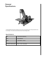
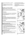
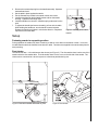
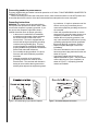
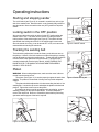
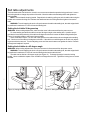
Operating Instructions — Parts Manual
1-Inch Belt / 8-Inch Disc Sander
Model 4002
Part No. 9078321
Revision A1
Table of Contents
Cover .................................................................................................................................... 1
General specifications .......................................................................................................... 3
Machine general safety warning ........................................................................................... 4
Safe operation precautions ................................................................................................... 5
Setting up the sander ............................................................................................................ 6
Operating instructions ........................................................................................................... 9
Adjustments ........................................................................................................................ 10
Typical operations ............................................................................................................... 13
Replacement parts ............................................................................................................. 15
Belt Sander Parts - Exploded View ................................................................................. 16
Belt Sander Parts - Parts List .......................................................................................... 17
Disc Sander Parts - Exploded View ................................................................................. 18
Disc Sander Parts - Parts List ......................................................................................... 19
2
General
Specifications
The Wilton Model 4002 sander is designed to serve the varying sanding needs of the professional or the
home hobbyist. The sander features both a belt and a disc sanding surface.
Specifications
Belt
1-inch wide x 42-inches long
Disc
8-inches diameter
Motor
1/3 horsepower, 1725 rpm
Power requirements
115 volts
Dimensions: Sander (LWH)
25.50 x 15.50 x 19.50 inches
3
WARNING
- Misuse of this machine can cause serious injury.
- For safety, machine must be set up, used and
serviced properly.
- Read, understand and follow instructions in the
Operating Instructions and Parts Manual which
was shipped with your machine.
When setting up machine:
- Always avoid using machine in damp or poorly
lighted work areas.
- Always be sure the machine support is securely
anchored to the floor or the work bench.
When using machine:
- Always wear safety glasses with side shields (See
ANSI Z87.1)
- Never wear loose clothing or jewelry.
- Never overreach - you may slip and fall.
When servicing machine:
- Always disconnect the machine from its electrical
supply while servicing.
- Always follow instructions in Operating Instructions
and Parts Manual when changing accessory tools
or parts.
- Never modify the machine without consulting
Wilton Corporation.
You—the stationary power tool user—
hold the key to safety.
Read and follow these simple rules for best results
and full benefits from your machine. Used properly,
Wilton’s machinery is among the best in design and
safety. However, any machine used improperly can
be rendered inefficient and unsafe. It is absolutely
mandatory that those who use our products be
properly trained in how to use them correctly. They
should read and understand the Operating Instructions and Parts Manual as well as all labels affixed to
the machine. Failure in following all of these warnings can cause serious injuries.
Machinery general safety warnings
4
1. Always wear protective eye wear when operating
machinery. Eye wear shall be impact resistant,
protective safety glasses with side shields which
comply with ANSI Z87.1 specifications. Use of
eye wear which does not comply with ANSI Z87.1
specifications could result in severe injury from
breakage of eye protection.
2. Wear proper apparel. No loose clothing or
jewelry which can get caught in moving parts.
Rubber soled footwear is recommended for best
footing.
3. Do not overreach. Failure to maintain proper
working position can cause you to fall into the
machine or cause your clothing to get caught
pulling you into the machine.
4. Keep guards in place and in proper working
order. Do not operate the machine with guards
removed.
5. Avoid dangerous working environments. Do not
use stationary machine tools in wet or damp
locations. Keep work areas clean and well lit.
6. Avoid accidental starts by being sure the start
switch is “OFF” before plugging in the machine.
7. Never leave the machine running while unattended. Machine shall be shut off whenever it is
not in operation.
8. Disconnect electrical power before servicing.
9.
10.
11.
12.
13.
14.
15.
16.
17.
Whenever changing accessories or general
maintenance is done on the machine, electrical
power to the machine must be disconnected
before work is done.
Maintain all machine tools with care. Follow all
maintenance instructions for lubricating and the
changing of accessories. No attempt shall be
made to modify or have makeshift repairs done to
the machine. This not only voids the warranty but
also renders the machine unsafe.
Machinery must be anchored to the floor.
Secure work. Use clamps or a vise to hold work,
when practical. It is safer than using your hands
and it frees both hands to operate the machine.
Never brush away chips while the machine is in
operation.
Keep work area clean. Cluttered areas invite
accidents.
Remove adjusting keys and wrenches before
turning machine on.
Use the right tool. Don’t force a tool or attachment to do a job it was not designed for.
Use only recommended accessories and follow
manufacturers instructions pertaining to them.
Keep hands in sight and clear of all moving parts
and cutting surfaces.
18. All visitors should be kept at a safe distance from
the work area. Make workshop completely safe
by using padlocks, master switches, or by
removing starter keys.
19. Know the tool you are using its application,
limitations, and potential hazards.
General electrical cautions
This sander should be grounded in accordance
with the National Electrical Code and local codes
and ordinances. This work should be done by a
qualified electrician. The sander should be
grounded to protect the user from electrical shock.
WARNING: Do not connect the sander to a
240 volt power source. The sander motor requires
120 volts alternating current.
Conductor length
0-50 feet
50-100 feet
Over 100 feet
Wire sizes
Caution: For circuits which are far away from the
electrical service box, the wire size must be increased in order to deliver ample voltage to the motor.
To minimize power losses and to prevent motor
overheating and burnout, the use of wire sizes for
branch circuits or electrical extension cords according to the following table is recommended.
AWG (American wire gauge) number
240 volt lines
NOT APPLICABLE
NOT APPLICABLE
NOT APPLICABLE
120 volt lines
No. 14
No. 12
No.8
Safety instructions for the 1-Inch belt / 8-Inch disc sander
WARNING: Do not operate your machine until it is
completely assembled and installed according to the
instructions.
WARNING: The dust generated by certain woods
and wood products can be injurious to your health.
Always operate machinery in well ventilated areas and
provide for proper dust removal. Use wood dust
collection systems whenever possible.
WARNING: This machine can be use for processing wood or metal products. However, combining
wood dust and metal filings can create a fire hazard.
Make sure that the dust collector is free of wood dust
deposits before processing metal products.
1. If you are not thoroughly familiar with the operation of belt and disc sanders, obtain advice from
your supervisor, instructor or other qualified
person.
2. If there is a tendency for the machine to tip over
or move during operation such as when sanding
long or heavy boards, the machine must be
securely fastened to a supporting surface.
3. Make sure the sanding belt is running in the
proper direction. The sanding belt must travel
downward when viewed from the front of the
machine.
4. Make sure the sanding belt is tracking correctly
in order that it does not run off the pulleys.
5. Make sure the sanding belt or disc is not torn or
loose.
6. Hold the work firmly when sanding.
7. Always hold the work firmly on the table when
sanding on the belt or disc. The only exception is
curved work performed on the top wheel of the
belt.
8. Always sand on the downward side of the disc
when using the disc portion of the machine, so
that the work is held securely on the table.
Sanding on the upward side of the disc could
cause the workpiece to fly up which could be
hazardous.
9. Always maintain a minimum clearance of 1/16inch or less between the table and the sanding
belt or disc.
10. Never wear gloves or hold the work with a rag
when sanding.
11. Sand with the grain of the wood.
12. Do not sand pieces of material that are too small
to be safely supported.
13. Avoid awkward hand positions where a sudden
slip could cause a hand to move into the sanding
belt or disc.
14. When sanding a large workpiece, provide
additional support at table height.
15. Never force the work. Slowing or stalling the
motor will cause overheating.
16. When sanding metal, never use a steady stream
of water on the work piece. Dip the workpiece in
water to cool it.
5
17. Do not sand or polish magnesium. It could catch
fire.
18. Always remove scrap pieces and other objects
from the belt and disc tables before turning the
machine ON.
19. Never perform layout, assembly or set-up work
on the tables while the sander is operating.
20. Always turn the machine OFF and disconnect the
cord from the power source before installing or
removing accessories.
21. Never leave the machine work area when the
power is ON or before the machine has come to
a complete stop.
Setting up the sander
WARNING: For your own safety, do not connect the sander to the
power source until the machine is completely assembled and you
have read and understood the entire Operating Instructions and Parts
Manual.
Unpacking
The sander is shipped complete in one carton. Carefully unpack the
machine and all loose items from the carton. If any parts are missing,
do not attempt to operate your sander until the missing parts are
obtained and installed correctly.
Cleaning
Remove the protective coating from the surfaces of the sander and
from any loose parts. This coating may be removed with a soft cloth
moistened with kerosene (do not use acetone, gasoline or lacquer
thinner for this purpose). After cleaning, cover the table surfaces with
a good quality paste wax.
Assembly
Figure 1. Installing the disc sander
table
Assembly of the sander is limited to the installation of the disc table
and the belt table. Proceed as described in the following paragraphs.
Assembling sanding disc table
6
WARNING: When assembling the sanding disc table, make certain
the motor is disconnected from the power source.
1. The sanding disc table is secured with two cap screws and nuts.
A hex wrench is required to tighten the screws.
2. Set the table on the rounded pockets in the support casting.
Install the nuts in the channel on the back side of the pockets.
3. Install the screws through the table and base casting into the nuts.
Tighten the screws.
4. Check for 1/16-inch clearance between the edge of the table and
the face of the disc. Adjust the clearance if required (see
Removal/Installation of the Disc).
Installing belt sander table
WARNING: When assembling the belt sander table, make certain the
motor is disconnected from the power source.
1. The belt table is secured with a spring-loaded locking handle
assembly. The handle assembly is disassembled for ease of
installation.
Figure 2. Securing the disc sander
table
2. Remove the screw and spring from the handle assembly. Separate
the handle and stud.
3. Set the table in place against the sander.
4. Put the flat washer provided in the sander carton on the stud.
5. Install the stud through the belt table bracket and into the sander
housing. Tighten the stud finger tight.
6. Install the handle over the stud. Install the spring and screw into the
stud.
7. To tighten the handle (and secure the table), pull out on the handle.
While holding the handle out, turn the handle counterclockwise.
Release the handle and tighten in a clockwise direction. Repeat as
required to secure the table.
Figure 3. Installing stud in table
bracket
Setup
Fastening sander to supporting surface
During operation the sander may have a tendency to slide or move about on the bench or table. It is recommended that the sander be fastened to the bench or table. Two holes are supplied in the sander base plate for
easy mounting.
Dust chutes
The sander has two 1-1/4 inch diameter dust chutes (see Figure 5). The disc sander chute is at the rear of the
sander under the disc sander table. The belt sander chute is in the cover on the left side of the sander. The
chutes can be connected to a vacuum system to collect dust particles during use.
7
Figure 4. Belt table installed and handle in place
Figure 5. Dust chutes
Connecting sander to power source
The motor supplied with your sander is wired for operation at 115 Volts. IT MUST NEVER BE CONVERTED TO
OPERATE AT 230 VOLTS !
Before connecting the motor cord to the power source, make certain the switch is in the OFF position and
be sure that the electric current is of the same characteristics as stamped on the motor nameplate.
Grounding instructions
WARNING: The sander must be grounded while in
use to protect the operator from electric shock. Make
sure that the receptacle is properly grounded. If you
are not sure the receptacle is grounded, have a
certified electrician check for proper grounding
• In the event of a malfunction or breakdown,
grounding provides a path of least resistance
for electric current to reduce the risk of
electric shock. This tool is equipped with an
electric cord having an equipment-grounding
conductor and a grounding plug. The plug
must be plugged into a matching outlet that is
properly installed and grounded in accordance
with all local codes and ordinances.
• Do not modify the plug provided—if it will not
fit have a new outlet installed by a qualified
electrician.
• Improper connection of the equipmentgrounding conductor can result in risk of
electric shock. The conductor with insulation
having an outer surface that is green with or
without yellow stripes is the equipment ground-
•
•
•
•
ing conductor. If repair or replacement of the
electric cord or plug is necessary do not
connect the equipment grounding conductor to
a live terminal.
Check with a qualified electrician or service
personnel if the grounding instructions are not
completely understood, or if in doubt as to
whether the tool is properly grounded. Use
only 3-wire extension cords that have 3-prong
grounding type plugs and 3-hole receptacles
that accept the plug, as shown in Figure 6.
Repair or replace damaged or worn cord
immediately.
This tool is intended for use on a circuit that
has an outlet and a plug that looks like the one
shown in Figure 6.
A temporary adapter, which looks like the
adapter illustrated in Figure 7, may be used to
connect this plug to a 2-pole receptacle, as
shown in Figure 7, if a properly grounded
outlet is not available.
8
Figure 6. Grounded plug in grounded receptacle
Figure 7. Grounded adapter connection
Operating instructions
Starting and stopping sander
The on/off switch (see Figure 8) is mounted in a switch box on the right
side of the sander base. Move the switch to the forward (ON) position to
start the sander. Move the switch to the rear (OFF) position to stop the
sander.
Locking switch in the OFF position
We recommend that the switch be locked in the OFF position when the
sander is not in use. The switch can be locked by pulling the switch
locking tab out of the switch toggle (see Figure 9). The switch will not
operate with the locking tab removed. If the switch toggle is removed
when the sander is running, it can be turned OFF once, but it cannot be
restarted without inserting the switch tab.
Figure 8. ON/OFF switch
Tracking the sanding belt
The belt tracking adjustment is set at the factory so the belt runs true on
the pulleys. However, if the belt tracks to one side of the pulleys, tracking
can be adjusted by turning the tracking knob . Turning the knob clockwise
moves the belt to the right when facing the sander. Turning the knob
counterclockwise will move the belt to the left. AVOID TURNING THE
KNOB TOO FAR. THE AMOUNT OF ADJUSTMENT REQUIRED IS
USUALLY VERY SLIGHT !
Platen
WARNING: When making adjustments, make sure the motor is disconnected from the power source.
The platen (see Figure 11) is used to properly support the work when
sanding. The platen is constructed of heavy steel to provide adequate
support.
The platen should be adjusted so it is almost touching the back of the
sanding belt. Loosen the cap screw and adjust the platen to the desired
position. Tighten the screw to secure the platen.
The platen can be removed for operations such as stripping, contour
sanding, polishing or other special operations. To remove the platen,
remove the cap screw. Be sure to reinstall the platen before performing
operations where support of the belt is required.
Figure 10. Adjusting belt tracking
Figure 9. Switch locking tab
9
Figure 11. Platen
Belt table adjustments
The belt sander table can be tilted or moved in or out to accommodate the operation being performed. Loosen
the locking handle to change the position of the table. Move the table to the desired position and tighten the
locking handle.
NOTE: The lock handle is spring loaded. Reposition the handle by pulling out on the handle and turning the
handle on the serrated locking stud. Release the handle and turn the locking handle to tighten or loosen the
table.
WARNING: To avoid trapping the work or fingers between the table and sanding belt, the table edge should
be positioned a maximum of 1/16-inch from the sanding belt.
Setting the belt table 90-degree stop
WARNING: When making adjustments, make sure the motor is disconnected from the power source.
For most sanding operations the table is set at a 90-degree angle to the sanding belt. A positive stop is
provided to insure fast positioning of the table at 90 degrees to the belt. Loosen the table locking handle (see
Figure 12) and tilt the table to the rear as far as possible.
Use a combination square. Put one end of the square on the table with the other end against the sanding
belt. Check to see if the table is 90 degrees to the belt. If the table is not at 90 degrees to the belt, turn adjusting screw with a hex wrench. Turn the adjusting screw until the screw bottoms out against the frame. Recheck
the angle and readjust if required.
Setting the belt table at a 45-degree angle
WARNING: When making adjustments, make sure the motor is disconnected from the power source.
WARNING: To avoid trapping the work or fingers between the table and sanding belt, the table edge should
be positioned a maximum of 1/16-inch from the sanding belt when the table is tilted.
The table can be tilted to a 45-degree angle (see Figure 13). To change the angle, loosen the locking
handle. Use a combination square to set the table to 45 degrees to the belt. Tighten the locking lever to secure
the table.
10
Figure 12. Setting belt table 90-degree stop
Figure 13. Setting belt table to 45-degree angle
Disc table adjustments
Adjusting the table angle
WARNING: When making adjustments, make sure the motor is disconnected from the power source.
WARNING: To avoid trapping the work or fingers between the table
and sanding disc, the table edge should be positioned a maximum of 1/16inch from the sanding disc.
The disc table is positioned at 90 degrees to the sanding disc for most
operations (see Figure 14). To check and see if the table is at 90 degrees, place a square, on the table with one end of the square against the
sanding disc. If an adjustment is necessary, loosen the cap screws and
move table until it is at 90 degrees to the sanding disc. Tighten the screws
to secure the table.
The disc table (see Figure 15) can be tilted downward 45 degrees.
Loosen the two cap screws, tilt the table to the desired angle, and tighten
the cap screws.
Adjusting the disc-to-table gap
WARNING: When changing abrasive belts, make sure the motor is
disconnected from the power source.
Adjust the sanding disc to leave a maximum of 1/16-inch gap between
the table and the disc. This can be accomplished by moving the sanding
disc in or out on the motor shaft (see Figure 16).
Use a T-handle type hex wrench. Put the wrench through the hole in
the top of the disc guard. Loosen the setscrew in the hub of the disc.
Move the disc in or out as needed to establish a 1/16-inch gap. When the
gap is established, tighten the setscrew.
Figure 14. Disc table at 90
degrees
Changing abrasive belts
WARNING: When changing abrasive belts, make sure the motor is
disconnected from the power source.
Remove the upper belt cover by removing the screw and nut (see
Figure 17). Remove the two knobs from the side cover. Remove the side
cover.
11
Figure 15. Disc table at 45
degrees
Figure 16. Adjusting disc-to-table gap
Figure 17. Removal of covers
Changing abrasive belts (continued)
Press down on the tracking knob to release belt tension (see Figure 18).
Remove the belt from the three pulleys. Install the replacement belt.
Replace side cover; secure the cover with two knobs.
IMPORTANT: Some belts have a directional arrow printed on the
inside of the belt. In these cases the belt must be installed so the directional arrow is in the same direction that the machine is running. The
sanding belt travels down the front of the machine.
Before installing the upper belt cover, start the sander and check belt
tracking. Adjust tracking if needed (refer to Tracking the Sanding Belt).
Changing abrasive discs
WARNING: When removing and installing abrasive discs, make certain
the motor is disconnected from the power source.
Remove the screws and nuts from the sanding disc table. Remove the
disc table.
Remove the lower disc guard (see Figure 19).
Loosen the setscrew in the hub of the disc. Remove the disc from
the motor shaft (see Figure 20).
Remove the old abrasive disc by peeling it from the sanding disc
plate.
Clean the disc plate thoroughly. Spray the face of the disc with 3M
Super 77 adhesive (or equivalent).
Remove the backing from the new abrasive disc and press the
abrasive disc firmly onto the disc plate (see Figure 21).
Figure 18. Removing the belt
Figure 19. Removal of lower disc
guard
12
Figure 20. Removal of sanding disc
Figure 21. Attaching sanding disc
Changing abrasive discs
(continued)
Align the keyway in the disc hub with the key on the motor shaft
(see Figure 22). Install the disc plate on the shaft. Position the
disc so the face of the disc is even with the edge of the upper
disc guard. Tighten the setscrew in the hub of the disc plate.
If necessary, adjust the position of the upper disc guard.
Loosen the screws and adjust the position of the upper disc
guard.
Replace the lower disc guard and the sanding disc table.
Miter gauge
Figure 22. Installation of the disc
A miter gage (see Figure 23) is supplied with the sander. The
miter gauge can be used on the disc table or the belt table. The
miter gauge can be set anywhere up to 45 degrees right or left.
Adjust the angle by loosening the knob, rotating the miter
gauge to the desired angle and retightening the knob.
Motor Belt
If the motor belt becomes loose, the belt can be tightened by
loosening the motor hold down nuts (see Figure 24). Slide to the
rear of the sander to tighten the belt. Hold the motor in position
and tighten the four motor hold down nuts.
Typical operations
The following are just some of the many operations that can be
performed with your Wilton Sander:
Sharpening a wood chisel on the sanding belt using a block of
wood. Use the block of wood to support the chisel and provide
Figure 23. Miter gauge (shown on disc
clearance for the chisel handle (see Figure 25).
table)
Sand a bevel in the block of wood in order to position the
wood as close as possible to the sanding belt and clamp the wood
to the table, as shown.
A cold chisel can also be sharpened on the belt table with the table tilted.
Figure 24. Tightening motor belt
Figure 25. Sharpening a wood chisel
13
Typical operations
(continued)
Sanding aluminum on the disc unit with the table tilted and using the
miter gauge as a guide (see Figure 26).
NOTE: Always sand on the left (downward) side of the sanding
disc, as shown. Sanding on the right (upward) side of the sanding
disc could cause the workpiece to fly up which could be hazardous.
Sanding outside curves on the belt unit with the platen removed
(see Figure 27).
Polishing using the accessory felt belt in place of the sanding
belt (see Figure 28).
NOTE: Most polishing operations are performed with the platen
removed.
Sanding in tight areas with the sanding belt (see Figure 29).
Figure 26. Sanding aluminum
Figure 27. Sanding outside curves
Figure 28. Polishing using a felt belt
14
Figure 29. Sanding in tight areas
Typical operations (continued)
Inside curves can be sanded on the upper sanding belt idler wheel (see
Figure 30). The upper cover can either be hinged back or removed.
Figure 30. Sanding inside curves
Replacement parts
This section provides exploded view illustrations that show the replacement parts for the 1-Inch Belt / 8-Inch
Disc Sander. Also provided are parts listings that provide part number and description. The item numbers
shown on the illustrations relate to the item number in the facing parts listing.
15
Order replacement parts from:
Wilton Corporation
300 South Hicks Road
Palatine, IL 60067
708/934-6000
FAX: 708\934-7813 or 1-800-626-9676
Identify the replacement part by the part number shown in the parts listing. Be sure to include the model
number and serial number of your machine when ordering replacement parts to assure that you will receive the
correct part.
16
Exploded View of Sander (Belt Sander Parts)
Item
No.
1
2
3
4
5
6
7
8
9
10
11
12
13
14
15
16
17
18
19
20
21
22
23
24
25
26
27
28
29
30
31
32
33
34
35
36
37
38
39
40
41
42
43
44
45
46
47
48
49
50
52
70
71
72
103
Part
Number
564003-1
564004-1
564005-1
564006-1
564007-1
564008-1
564009-1
564015-1
564016-1
564017-1
564018-1
564019-1
564025-1
564026-1
564027-1
564028-1
564029-1
564033-1
564034-1
564035-1
564036-1
564029-1
564037-1
564038-1
564039-1
564043-1
564044-1
564045-1
564046-1
564047-1
564048-1
564029-1
564037-1
564049-1
564051-1
564052-1
564010-1
564011-1
564012-1
564013-1
564014-1
564030-1
564031-1
564032-1
564054-1
564055-1
564058-1
564057-1
564063-1
564059-1
564068-1
564062-1
564061-1
564064-1
564065-1
564066-1
564067-1
564069-1
564046-1
564045-1
564044-1
564056-1
Description
Hex. Socket Head Screw (M10 x 40 MM)
Flat Washer (12 MM)
Spring
Spacer
Tracking Adjustment Screw
Spring
Support
Spring Pin (M3 x 20 MM)
Idler Shaft
Idler Shaft
Hex. Soc. Set Screw (M5 x 5 MM)
Hex. Soc. Set Screw (M5 x 12 MM)
Drive Pulley
Retaining Plate
Slot Hd. Mach. Screw (M4 x 12 MM)
Lock Washer (4.1 MM)
Ball Bearing
Key
Main Drive Shaft
Ball Bearing
Frame
Ball Bearing
Idler
Flat Washer (6.4 MM)
Upper Cover
Hex. Socket Head Screw (M6 x 10MM)
Hex. Socket Head Screw (M10 x 20MM)
Lock Washer (10 MM)
Flat Washer (10 MM)
Platen
Spacer
Ball Bearing
Idler
Retaining Ring
Hex. Socket Setscrew (M5 x 16 MM)
Drive Wheel
Sanding Belt - 50 Grit
Sanding Belt - 80 Grit
Sanding Belt - 120 Grit
Sanding Belt - 220 Grit
Sanding Belt - 320 Grit
Abrasive Belt, Non-woven - Fine
Abrasive Belt, Non-woven - Medium
Abrasive Belt, Non-woven - Coarse
Nut
Washer
Bolt
Knob
Washer
Cover
Lockwasher
Table
Knob
Clamp Assembly
Special Washer
Bracket
Flat Washer (8,4 MM)
Screw (M8 x 15 MM)
Flat Washer (10 MM)
Lock Washer (10 MM)
Hex. Socket Head Screw (M10 x 20MM)
Rotation Label
17
18
Exploded View of Sander (Disc Sander Parts)
Item
No.
53
54
55
56
57
59
60
61
62
63
64
66
67
68
69
80
81
99
100
101
102
103
106
107
--110
111
112
113
114
120
121
122
123
124
125
130
131
132
137
138
139
140
141
142
143
144
145
Part
Number
5640711
5640721
5640731
5640741
5640751
5640461
5640761
5640771
5640781
5640791
5640811
5640671
5640821
5640671
5640831
5640841
5628791
5640201
5640211
5640221
5640871
5640181
5640881
5640561
5640921
5640922
5640931
5640941
5640961
5640971
5640981
5640991
5641011
5641021
5632851
5641041
5641051
5641241
5640461
5641121
5641131
5641141
5641161
5641171
5641181
5640781
5641191
5641211
5640781
5641221
5641231
Description
Hex. Socket Head Screw (M5 x 12 MM)
Drive Pulley
Key
Motor
Hex Nut (M10)
Flat Washer (10 MM)
Carriage Head Screw (M10 x 12MM)
Base
Pan Head Screw (M4 x 20 MM)
External Tooth Washer (4 MM)
Hex. Head Screw (M8 x 20 MM)
Flat Washer (8.4 MM)
Rubber Foot
Flat Washer (8.4 MM)
Hex. Nut (M 8)
Allen Wrench (2.5 MM)
Allen Wrench (8 MM)
Sanding Disc - 50 Grit
Sanding Disc - 80 Grit
Sanding Disc - 120 Grit
Disc Plate
Soc. Hd. Mach. Screw (M5 x 5 MM)
Screw
Rotation Label
pulley cover - belt/disc
pulley cover - belt only
V-Belt
Miter Gauge Assembly
• Hand Knob (1/4-Inch)
• Flat Washer (3/16-Inch)
• Miter Gauge Body
• Spring Pin (M4 x 10 MM)
• Guide Bar
Table
Cap Screw
Washer
Nut
Cap Screw
Washer
Side Guard
Pan Hd. Screw (M4 x 6 MM)
Support
Switch
Switch Key
Switch Cover
Pan Head Screw (M4 x 12 MM)
Cord
Heyco Bushing (5/8-Inch)
Pan Head Screw (M4 x 12 MM)
Cable Clamp
Connector
19
20
Wilton Corporation
300 South Hicks Road
Palatine, IL 60067
708/934-6000
FAX 1-800-626-9676
Industrial Products Group:
Wilton Tool
Wilton Machinery
Anderson Products
Anderlex Abrasives