1
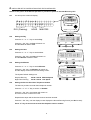
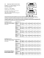
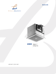
ABC
WHOLE HOUSE
HEAT RECOVERY UNIT
Installation, Connection and set up Instructions
READ INSTRUCTIONS IN CONJUNCTION WITH ILLUSTRATIONS
PLEASE SAVE THESE INSTRUCTIONS
Installation and Wiring Instructions for Air Minder Plus
Heat Recovery Unit (HRU).
IMPORTANT:
READ THESE INSTRUCTIONS BEFORE COMMENCING THE INSTALLATION
DO NOT install this product in areas where the following may be present or occur:
• Excessive oil or a grease laden atmosphere.
• Corrosive or flammable gases, liquids or vapours.
• Ambient temperatures higher than 50°C or less than –10°C.
• Relative humidity above 90%
• Possible obstructions which would hinder the access to or removal of the Unit.
SAFETY AND GUIDANCE NOTES
•
•
•
•
•
•
•
•
•
•
•
•
•
•
•
•
•
•
•
All wiring must be in accordance with building Regulations and the current I.E.E. Wiring
Regulations (BS7671), or the appropriate standards of your country. The installation should be,
inspected and tested by a suitably qualified person after completion.
The Unit should be provided with a local double pole isolator switch having a contact separation of
at least 3mm.
Ensure that the mains supply (Voltage, Frequency and Phase) complies with the rating label.
It is recommended that the connection to the unit is made with flexible cable.
This Unit should not be used where it is liable to be subject to direct water spray from hoses etc.
This HRU’s condensate drain must be connected to the building foul water drainage system.
If an extract grille associated with the HRU is sited in a room containing a fuel burning appliance,
the installer must ensure that air replacement is adequate for both appliances.
Ensure that the HRU’s external grilles are a minimum of 2m apart and located at least 600mm
away from any flue outlet.
If the ductwork passes through an unheated loft void or similar location, it should be insulated.
Certain applications may require the installation of sound attenuation to achieve the sound levels
required.
The unit must not be connected directly to a Cooker Hood or Tumble Dryer.
The Condensate Waste pipe must be insulated if it passes through an unheated loft void.
The Supply and Exhaust Valves must be fully opened prior to commissioning.
The Supply air must be drawn from the exterior of the property.
The internal Drain Tray condensate outlet should be clear of debris prior to commissioning.
The Supply and Exhaust Valves must be positioned a minimum of 300mm from a wall to enable
the airflow measuring equipment to fit correctly over the Valve.
The unit should be allowed to stabilise during commissioning for a minimum period of 5 minutes
when changing between the Low, Medium and Boost speeds.
When the unit is fitted in a new build property the Supply and Extract Filter should be checked at
one month intervals for the first six months.
When the unit is used in conjunction with open flue appliances (see Frost Protection, section I
pg 11) an electrical duct heater must be placed in the Supply (cold fresh air duct, colour green).
PRE-INSTALLATION.
1. Measure the access to ensure that the HRU will pass through the access into the loft space (See below).
The Unit can be installed fully assembled or where the hatch space is limited it is designed so that it can
pass through a 450mm square hole and be assembled in the loft void.
1500mm
Minimum
Clearance
450mm
450mm
2. The following factors must be considered prior to the installation of the HRU:
¾ The Unit’s Condensate drain should be connected to the building foul water drainage system.
¾ The Unit must be positioned to allow for the access and removal of the Unit‘s Filters and Heat
Recovery Cube for maintenance purposes.
¾ Avoid sudden ductwork bends or transformations close to the Unit.
¾ Use flexible connections between the rigid ductwork and the unit spigots.
2
AIRMINDER PLUS has been designed and packaged to be easily installed by one person.
For ease of handling and installation the Air Minder Plus HRU is delivered in two cartons:
Carton 1
CARTON 1
ITEM 1
1 – MAIN BODY
2 – CONDENSATION TUBING
3 – DRAIN ELBOW
4 – FOUR FEET / FIXINGS
5 _ ANGLED MOUNTING BRACKETS
6 – SET OF FOUR CONNECTION SPIGOTS
7 – L.C.D. CONTROLLER
Carton 2
8 – TWO FAN BLOWER UNITS
9 – TWO INLETS
ITEM 5
CARTON 2
ITEM 6
(4-OFF Sets)
ITEM 8 (2 off)
ITEM 4
(4-OFF)
ITEM 2
ITEM 9 (2 off)
ITEM 7
ITEM 3
A. PREPARATION.
1. Remove the contents from Carton 1.
2. Remove the Air Filters from the main body.
3. Release the six yellow locking Straps
(The two end Straps have locking screws) and lift the
Top Housing away from the Base Housing.
4. If the HRU is to be passed through a restricted space, release
the screws on the side of the Heat Recovery Cube and remove the Cube.
3
B. ASSEMBLY.
1. Fit the four feet to the Base Housing for floor fixing.
2. Insert the Heat Recovery Cube into the Base Section and secure the Cube into position.
3. Pull out the four Spigot Locking Clips.
4. Locate the Fan Blower Units (Item 8) from carton 2 either side of the Electrical Control Box, and the Inlets
(Item 9) into the retaining grooves on the other side of the Base Housing.
Inlet
(Item 9)
Inlet
(Item 9)
Fan blower
unit
(Item 8)
Electrical control box
Fan blower
unit
(Item 8)
Ensure the Fan Units (Item 8) are on either side of the Electrical
Control Box and the Inlets (Item 9 ) are on the opposite side.
Unit Locking
Straps
5. Locate the Top Housing onto the Base
Housing and secure into position using
the yellow Locking Straps and tighten
the locking screws.
Filter B
Filter A
Spigot Locking Clips
(At the base of the spigots)
Spigot Locking Clips
(At the base of the spigots)
6. Rotate the Blower Units and the Inlets to the most convenient position to suit the direction of the ductwork.
7. Lock the spigots into position by Pushing the yellow Spigot Locking
Clips into the Base Housing, until they are flush.
8. Insert the Air Filters (A and B) into the Top Section.
4
C MOUNTING
Note: Ensure that horizontal units are installed with a 5° fall towards the condensate drain point.
TYPICAL MOUNTING
1. The HRU should be secured to the support timbers by 4 Woodscrews (25mm long x N°10 Round Head)
2. The angled brackets assembled with the Anti Vibration Mountings supplied to be attached to the feet of
the HRU orientate to the diagram below for loft or ceiling mounting.
Ceiling mounting
Loft mounting
Fit assembled 5° angled brackets
Ceiling joist
Roofing joist
Condensate connection
Condensate connection
Fit assembled 5° angled brackets
D. CONNECTION SPIGOTS
SPIGOT ASSEMBLY
Spigot Sizes: AM PLUS 290 – 150mm ø
AM PLUS 375 – 200mm ø
Assembled spigot
1. Apply clear silicone sealant (Not supplied) to each spigot assembly as shown. Wipe off any excess
sealant to make a good air tight seal.
2. For convenience the connection spigots can be fixed in one of four positions, using the bayonet
design.
5
(Colour: Orange)
(Colour: Green)
EXTRACT
(Warm Stale Air)
SUPPLY
(Cold Fresh Air)
from the Dwelling
Intake from
Outside
(Colour: Yellow)
(Colour: Red)
DISCHARGE
(Cold Stale Air)
to Outside
SUPPLY
(Warm Fresh Air)
Electrcal
Control Box
to the
Dwelling
E. CONDENSATE DRAIN.
Installation.
1.
Site for
fitting of
drain elbow
Remove the quarter turn Drain Plug seal
(item1) shown and insert the quarter turn
Drain Elbow (Item 3), connect the Tubing
(Item 2) to the Drain Elbow and secure with
a Clip Band. Align the Drain Elbow with the
waste pipe to ensure there are no abrupt
bends or restrictions in the Tubing.
Electrical control box
View inside base housing for loft mounting
Note: Ensure that units are installed with a 5° fall
towards the condensate drain point.
2.
Connect the tubing (Item 2) to Drain
Elbow and secure into position with
a Clip Band. Align the elbow with the
condensate waste pipe to ensure
there are no abrupt bends or
restrictions in the Tubing.
3.
Install the condensate drainage
Tubing in accordance with the
diagram.
4.
Ensure the water trap is below the
Drain Elbow outlet ‘A’.
Site for fitting
of drain elbow
Electrical control
box aperture
View inside top housing for ceiling mounting
DRAIN
ELBOW
SILICON SEALER
A
CLIP BAND
WATER TRAP
6
FALL TOWARDS
THE BUILDINGS
DRAINAGE SYSTEM
INSTALLING THE CONTROLLER
1.
Insert a small flat bladed screwdriver into the small slot at the base of the controller, push the release
catch in and gently lever upwards to remove the front cover of the controller by pulling the cover away
from the back box.
2.
Fix the back box in the position required using the 2 key hole slots the countersink at the top of the slots
provides permanent fixing.
Fixing Slots.
CONTROLLER
1. The 4 core SELV cable is wired
to the controller terminals in the
following order:
L.C.D Controller
2. Replace the Controller’s front
cover.
AB CD
BLUE / WHITE
ORANGE / WHITE
WHITE / ORANGE
WHITE / BLUE
AB CD
JP 200
CON 7
BOOST
HRU Control Panel
F. WIRING.
WARNING: THE FAN AND ANCILLARY CONTROL EQUIPMENT MUST BE ISOLATED
FROM THE POWER SUPPLY DURING THE INSTALLATION / OR MAINTENANCE.
Unscrew the three retaining screws and
remove the Electrical Control Box Cover.
7
Connections.
External Sensor
Connector
(Where appropriate)
Internal
Temperature
Sensors
(Pre-Connected)
Summer Bypass
Pre-Connected
(If Fitted)
N
~
L
Dip Switches
1 Phase Supply
(220-240V 50Hz).
3A FUSE
Controller
Connector
L N
AB CD
JP 200
CON 7
BOOST
(Colour: Yellow)
(Colour: Red)
HRU Control Panel
Motor
Connections
FANS.
1. Route the blower unit cable in the Cable Retaining Groove on the Fan Blower and around the outside
groove to the base of the Electrical Control Box.
2. Connect the Connector Plugs from each Blower Unit to the Terminal Connection Sockets on the
Connection Board.
3. Feed any excess cable into the recesses on either side of the Electrical Control Box and clamp the Cable
securely into position.
MAINS CONNECTION.
¾
Connect the mains power supply to the HRU.
HOUSE VOLUME SELECTION.
¾
Select the Total House Volume from the table below and set the Dip Switches to the speed required.
AM PLUS 290
House Volume
AM PLUS 375
House Volume
¾
¾
¾
¾
Setting 1
Setting 2
Setting 3
Setting 4
265m3
310m3
355m3
400m3
Low 60 m3/h
Med 120 m3/h
High 200 m3/h
Low 70 m3/h
Med 140 m3/h
High 230 m3/h
Low 80 m3/h
Med 160 m3/h
High 270 m3/h
Low 90 m3/h
Med 180 m3/h
High 290 m3/h
400m3
466m3
555m3
600m3
Low 90 m3/h
Med 180 m3/h
High 290 m3/h
Low 100 m3/h
Med 210 m3/h
High 330 m3/h
Low 120 m3/h
Med 250 m3/h
High 360 m3/h
Low 135 m3/h
Med 270 m3/h
High 380 m3/h
Replace the HRU’s Control Box’s Cover.
Switch the Unit On at the Switch Fused Spur box and follow the controller set up sequence, described in
the next Section G.
Ensure the HRU is working correctly.
Note: The System operating noise level will be significantly higher when operating on the High speed.
8
G INSTALLER SET UP INSTRUCTIONS FOR THE CONTROLLER
Switch on the power at the Switch Spur Box to provide the power to the Heat Recovery Unit.
G:1
On start up the screen will display:
S e t
S u n
DAY (Flashing)
G:2
>
C I o c k
HOUR
MINUTES
Setting the Day
S e t
C I o c k
0 : 0 0
T u e
>
>
Press the “ Set ” Key, the Day will remain on
and the Hour will start to flash.
SET
Setting the Hour
Press the “Λ ” or “ V ” Key to set the Hour.
S e t
C I o c k
1 1 : 0 0
T u e
>
>
Press the “ Set ” Key, the Hour will remain on
and the Minutes will start to flash.
G:4
SET
0 : 0 0
Press the “Λ ” or “ V ” Key to set the Day.
G:3
0 : 0 0
>
S e t
C l o c k
S u n
SET
Setting the Minutes
Press the “Λ ” or “ V ” Key to set the Minutes.
Press the “ Set ” Key, the Minutes will remain on
and the display will scroll to the next setting screen.
Daytime Running
Night-Time Running
G:5
T u e
1 1 : 1 5
>
S p e e d
>
The System Default Settings are:
M e d i u m
SET
06:00 to 22:30 Medium Speed
22:30 to 06:00 Low Speed
Setting the Service Providers Telephone Number
The Service provider can enter their telephone number.
Press the “Λ ” of “ V ” Key to set the 1st Number.
Press the “ Set ” Key, the Number will remain on
and move to the 2nd number to be set.
Repeat these steps until the Service Number has been entered.
Press the “ Set ” Key, until the display screen displays the Normal Running Screen (see G:4 screen).
Press “V” Key for 5 seconds to reset the telephone service number.
9
G:6
Adjusting the Medium Airflow Rates
Ru n n i n g
Press the “ V ” “Λ ” and `set’ Keys for more than
5 seconds until the display changes
to the screen opposite.
T i me
0 0 0 2 0
v
SET
v
Press the “Λ ” until the display
changes to the screen opposite.
The present rate number for each is shown.
Press `SET’ to adjust intake rate,
`SET’ again for Exhaust rate and SET again to
store the new values.
I n t a k e
E x h a u s t
M0 8
M0 8
v
SET
v
The external pressure head available is a minimum of 200Pa at all speeds. However, the higher the
resistance of the system the higher will be the power that is consumed. Take care to design, install and
commission the system with the least resistance in order to minimise power consumption.
The figures quoted are nominal air flows which are subject to the design, installation and commissioning of the
complete ventilation system. The medium and boost inlet and extract flows can be adjusted independently via
the controller as described in the Fitting and Wiring information.
Air Minder Plus 290
rate numbers and corresponding
Airflow rates, Nominal setting
shown bold
House size 1
Low
1
Medium
2
Boost
9
60
70 3
200
House size 2
Low
2 70
Medium
3 80 4
Boost
10 230
House size 3
Low
3 80
Medium
4 90 5
Boost
11 270
House size 4
Low
4 90
Medium
5 120 6
Boost
12 290
Air Minder Plus 375
rate numbers and corresponding House size 1
Low
1
Airflow rates, Nominal setting
Medium
2
shown bold
Boost
9
90
100 3
290
House size 2
Low
2 100
Medium
3 120 4
Boost
10 330
Press the Boost Button *
for 12 seconds to reset to
factory default setting.
House size 3
Low
3 120
Medium
4 135 5
Boost
11 360
House size 4
Low
4 135
Medium
5 180 6
Boost
12 380
10
80 4
90 5
120 6
140 7
160 8
180
90
5
120 6
140 7
160 8
180 9
200
120 6
140 7
160 8
180 9
200 10 230
140 7
160 8
180 9
200 10 230 11 270
120 4
135 5 180 6 210 7
240 8
270
290
135 5 180 6
210 7 240 8
270 9
180 6 210 7
240 8
290 10 330
210 7
270 9 290 10 330 11 360
240 8
270 9
IF DIFFERENT RUNNING TIMES ARE REQUIRED, REFER TO THE USER HAND BOOK.
G:7
Adjusting the Boost Airflow Rates
Ru n n i n g
Press the “ V ” “Λ ” and `set’ Keys for more than
5 seconds until the display changes
to the screen opposite.
T i me
0 0 0 2 0
v
SET
v
Press the “Λ ” until the display
changes to the screen opposite.
The present rate number for each is shown.
Press `SET’ to adjust intake rate,
`SET’ again for Exhaust rate and SET again to
store the new values.
v
Air Minder Plus 290
rate numbers and corresponding
House size 1
Airflow rates, Nominal setting
Low
1
shown bold
Medium
5
Boost
3
I n t a k e
E x h a u s t
B1 2
B 1 2
v
SET
60
120
80 4
90 5
120 6
140 7
House size 2
Low
2 70
Medium
6 140
Boost
4 90 5
120 6
140 7
160 8 180 9 200 10 230
House size 3
Low
3 80
Medium
7 160
Boost
5 120 6
140 7
160 8
180 9 200 10 230 11 270
House size 4
Low
4
Medium
8
Boost
6
160 8 180 9
200 10 230 11 270 12 290
135 5
210 7 240 8
90
180
140 7
Air Minder Plus 375
rate numbers and corresponding House size 1
Low
1 90
Airflow rates, Nominal setting
shown bold
Medium
5 180
Boost
3 120 4
180 6
160 8
180 9
200
270 9 290
House size 2
Low
2 100
Medium
6 210
Boost
4 135 5 180 6 210 7
240 8 270 9 290 10 330
House size 3
Low
3 120
Medium
7 240
Boost
5 180 6
270 9 290 10 330 11 360
210 7
House size 4
Low
4 135
Medium
8 270
Boost
6 210 7 240 8
11
240 8
270 9 290 10 330 11 360 12 380
H EXTERNAL SENSOR CONNECTIONS
Select the required External Sensors.
Ambient Response
Humidity Sensor
(56 35 50)
Ecotronic
Humidity Sensor
(56 35 32)
Visionex PIR
(45 07 26)
5
4
3
N
5
L
4
3
N
N
~
L
L
1 Phase Supply
(220-240V 50Hz).
3A FUSE
L.C.D Controller
L N
AB CD
JP 200
AB CD
CON 7
BOOST
HRU Control Panel
BLUE / WHITE
ORANGE / WHITE
WHITE / ORANGE
WHITE / BLUE
I FROST PROTECTION.
Standard Frost Protection.
When the external intake air temperature is between 0ºC and -5ºC the defrost mode will automatically activate.
This mode will reduce the supply airflow rate and increase the extract airflow rate to prevent frost forming on
the heat exchanger.
When the external intake air temperature is below -5ºC the defrost mode will automatically activate. This
mode will automatically switch off the supply fan, the extract fan will continue to run at a reduced rate to
prevent frost forming on the heat exchanger.
Open flue appliances (F/FB
Models Only).
In installations where a negative
pressure within the dwelling is
not permitted, a link must be
fitted between the JP 200
terminals on the HRU Control
Panel. When this link is in
position and the external air
temperature drops below -1ºC
the summer bypass will open
and the supply fan will continue
to run, allowing external air to
bypass the heat exchanger and
enter the dwelling.
JP 200
CON 7
BOOST
AB CD
L N
JP 200
Blue Link
HRU Control Panel
J SUMMER BYPASS.
The Bypass damper activates when the outside air temperature is equal to or below the pre-set ‘Comfort
Temperature’ (adjustable between 16° and 30°C). The unit’s internal damper opens allowing the cooler fresh
air from the outside to bypass the Heat Recovery Cube and reduce the internal temperature to the required
pre-set ‘Comfort Temperature’.
When the inside air temperature reaches the pre-set ‘Comfort Temperature’ the Bypass Damper closes.
12
VENT-AXIA SALES CENTRES
ENGLAND & WALES NATIONAL CALL CENTRE
Newton Road, Crawley
West Sussex
RH10 9JA
Telephone: 01293 530202
Fax:
01293 565169
REPUBLIC OF IRELAND
Vent-Axia Ventilation Ltd.
921 Western Road Industrial Estate
Naas Road, Dublin 12.
Telephone: (01) 450 4133
Fax:
(01) 450 4570
Did you find these instructions easy to use?
We value your comments, contact us via:
Email: [email protected]
The Vent-Axia Guarantee
Applicable only to products installed and used in the United Kingdom. For details of the Guarantee outside of the
United Kingdom contact your local supplier.
Vent-Axia guarantees this product for two years from the date of purchase against faulty material or workmanship.
In the event of any part being found to be defective, the product will be repaired, or at the Company’s discretion the
product will be replaced without charge, provided that the product:
1).
2).
3).
4).
Has been installed and used in accordance with the instruction given with each unit.
The electricity supply complies with the rating label.
Has not been misused, neglected or damaged.
Has not been modified or repaired by any person not authorised to do so by Vent-Axia.
IF CLAIMING UNDER THE TERMS OF THE GUARANTEE
Please return the complete product, carriage paid to your original supplier by post or in person. Please ensure that it
is adequately packed and accompanied by a letter clearly marked ‘Guarantee Claim’ stating the nature of the fault
and providing proof of the date and source of purchase.
As part of the policy of continuous product improvement Vent-Axia reserve the right to alter specifications without notice
Head Office: Fleming Way, Crawley, West Sussex RH10 9YX
Tel: 01293 526062 Fax: 01293 551188
Internet site at: www.vent-axia.com
42 57 67 O
0608
13