1
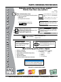
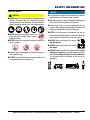
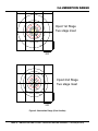
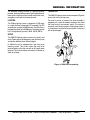
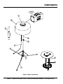
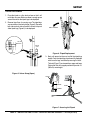
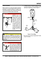
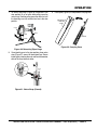
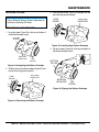
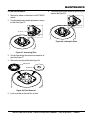
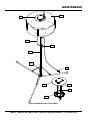
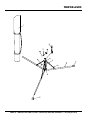
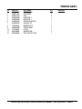
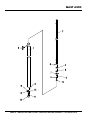
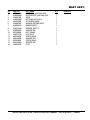
OPERATION AND PARTS MANUAL GloBug SERIES GB3LED LIGHTING SYSTEM Revision #0 (3/18/14) To find the latest revision of this publication, visit our website at: www.multiquip.com THIS MANUAL MUST ACCOMPANY THE EQUIPMENT AT ALL TIMES. TABLE OF CONTENTS GB3LED LIGHTING SYSTEM Table Of Contents..................................................... 2 Parts Ordering Procedures....................................... 3 Safety Information................................................. 4-7 Specifications........................................................... 8 Dimensions............................................................... 9 Illumination Range.................................................. 10 General Information................................................ 11 Components...................................................... 12-13 Setup................................................................. 14-16 Operation........................................................... 17-19 Maintenance...................................................... 20-23 Wiring Diagram....................................................... 24 Troubleshooting...................................................... 25 Explanation Of Code In Remarks Column............. 26 Suggested Spare Parts.......................................... 27 Component Drawings Nameplate And Decals...................................... 28-29 Electrical Assy.................................................... 30-31 Tripod Assy........................................................ 32-33 Mast Assy.......................................................... 34-35 Terms And Conditions Of Sale — Parts................. 36 NOTICE Specifications and part numbers are subject to change without notice. PAGE 2 —GB3LED LIGHTING SYSTEM • OPERATION AND PARTS MANUAL — REV. #0 (03/18/14) www.multiquip.com PARTS ORDERING PROCEDURES Ordering parts has never been easier! Choose from three easy options: Best Deal! Order via Internet (Dealers Only): Effective: January 1st, 2006 If you have an MQ Account, to obtain a Username and Password, E-mail us at: parts@multiquip. com. Order parts on-line using Multiquip’s SmartEquip website! View Parts Diagrams Order Parts Print Specification Information To obtain an MQ Account, contact your District Sales Manager for more information. Use the internet and qualify for a 5% Discount on Standard orders for all orders which include complete part numbers.* Goto www.multiquip.com and click on Order Parts to log in and save! Note: Discounts Are Subject To Change Order via Fax (Dealers Only): All customers are welcome to order parts via Fax. Domestic (US) Customers dial: 1-800-6-PARTS-7 (800-672-7877) Fax your order in and qualify for a 2% Discount on Standard orders for all orders which include complete part numbers.* Note: Discounts Are Subject To Change Order via Phone: Domestic (US) Dealers Call: 1-800-427-1244 Non-Dealer Customers: Contact your local Multiquip Dealer for parts or call 800-427-1244 for help in locating a dealer near you. International Customers should contact their local Multiquip Representatives for Parts Ordering information. When ordering parts, please supply: Dealer Account Number Dealer Name and Address Shipping Address (if different than billing address) Return Fax Number Applicable Model Number Quantity, Part Number and Description of Each Part Specify Preferred Method of Shipment: UPS/Fed Ex DHL Priority One Truck Ground Next Day Second/Third Day NOTICE All orders are treated as Standard Orders and will ship the same day if received prior to 3PM PST. WE ACCEPT ALL MAJOR CREDIT CARDS! GB3LED LIGHTING SYSTEM • OPERATION AND PARTS MANUAL — REV. #0 (03/18/14) — PAGE 3 SAFETY INFORMATION Do not operate or service the equipment before reading the entire manual. Safety precautions should be followed at all times when operating this equipment. Failure to read and understand the safety messages and operating instructions could result in injury to yourself and others. Potential hazards associated with the operation of this equipment will be referenced with hazard symbols which may appear throughout this manual in conjunction with safety messages. SAFETY MESSAGES The four safety messages shown below will inform you about potential hazards that could injure you or others. The safety messages specifically address the level of exposure to the operator and are preceded by one of four words: DANGER, WARNING, CAUTION or NOTICE. SAFETY SYMBOLS DANGER Indicates a hazardous situation which, if not avoided, WILL result in DEATH or SERIOUS INJURY. WARNING Indicates a hazardous situation which, if not avoided, COULD result in DEATH or SERIOUS INJURY. CAUTION Indicates a hazardous situation which, if not avoided, COULD result in MINOR or MODERATE INJURY. NOTICE Addresses practices not related to personal injury. PAGE 4 —GB3LED LIGHTING SYSTEM • OPERATION AND PARTS MANUAL — REV. #0 (03/18/14) SAFETY INFORMATION GENERAL SAFETY CAUTION NEVER operate this equipment without proper protective clothing, shatterproof glasses, respiratory protection, hearing protection, steel-toed boots and other protective devices required by the job or city and state regulations. NEVER operate this equipment when not feeling well due to fatigue, illness or when under medication. NEVER operate this equipment under the influence of drugs or alcohol. NOTICE This equipment should only be operated by trained and qualified personnel 18 years of age and older. Whenever necessary, replace nameplate, operation and safety decals when they become difficult read. Manufacturer does not assume responsibility for any accident due to equipment modifications. Unauthorized equipment modification will void all warranties. NEVER use accessories or attachments that are not recommended by Multiquip for this equipment. Damage to the equipment and/or injury to user may result. ALWAYS know the location of the nearest fire extinguisher. ALWAYS know the location of the nearest first aid kit. ALWAYS check the equipment for loosened threads or bolts before starting. DO NOT use the equipment for any purpose other than its intended purposes or applications. ALWAYS know the location of the nearest phone or keep a phone on the job site. Also, know the phone numbers of the nearest ambulance, doctor and fire department. This information will be invaluable in the case of an emergency. GB3LED LIGHTING SYSTEM • OPERATION AND PARTS MANUAL — REV. #0 (03/18/14) — PAGE 5 SAFETY INFORMATION LIGHTING SYSTEM SAFETY WARNING NEVER disconnect any emergency or safety devices. These devices are intended for operator safety. Disconnection of these devices can cause severe injury, bodily harm or even death. Disconnection of any of these devices will void all warranties. CAUTION NEVER attempt service on a running machine. NOTICE To prevent the lighting system from overturning, NEVER use in winds that exceed 22 mph (10 m/s). The lighting system should only be used in temperatures between 23° to 104°F (-5° to 40° C). Failure to comply with these operating parameters could cause the lamp to malfunction and shorten the ballast life. ALWAYS keep the lighting system in proper running condition. Fix damage to lighting system and replace any broken parts immediately. ALWAYS store equipment properly when it is not being used. Equipment should be stored in a clean, dry location out of the reach of children and unauthorized personnel. LAMP SAFETY WARNING NEVER attempt to replace lamp with the power on. Always unplug the power cord from the generator or power source when changing the lamp. NOTICE NEVER leave any grease or oil residue on lamp surface when replacing or removing lamp. This can create hot spots, reducing the service life of the lamp. ALWAYS make sure lamp surface is clean and dry. ALWAYS replace with MQ recommended type lamp. See parts section of this manual. If applicable, ALWAYS make sure the lamp guard is installed correctly. NEVER deform the lamp guard. NEVER unplug the lamp’s AC power cable during operation. ALWAYS have a trained technician to install and remove lamp or replace any damaged fixture wiring. TRANSPORTING SAFETY NOTICE When transporting the tripod lighting system, if applicable, always place in stow position and place tripod in its carrying case. ALWAYS remove balloon/lamp assembly from the mast when transporting lighting system. This will prevent damage to the bulb due to vibration. NEVER leave the balloon/lamp exposed during transport. Exposure to excess wind or rain could damage the balloon’s nylon cover. ALWAYS place balloon inside its protective cover during transport. Be sure the cover is secured tightly around the balloon/lamp assembly. ALWAYS allow a sufficient amount of time for the lamp to cool before changing. The possibility exists of severe burns. CAUTION NEVER use force when installing the lamp. Excessive force could cause the lamp to break, causing bodily harm. PAGE 6 —GB3LED LIGHTING SYSTEM • OPERATION AND PARTS MANUAL — REV. #0 (03/18/14) SAFETY INFORMATION BALLOON SAFETY ELECTRICAL SAFETY WARNING DANGER To prevent serious burns, NEVER touch or unzip the balloon envelope when the lamp is on. Lighting system is equipped with a ground pin on the power plug. For your protection, ALWAYS complete the grounding path. NEVER insert the AC power plug into a 2-prong receptacle to operate lighting system. CAUTION ALWAYS keep the balloon away from sharp objects and excessive amounts of heat. NOTICE To prevent balloon deformation, NEVER use lighting system in strong winds. DO NOT place the balloon inside its protective cover until the lamp has had a sufficient amount of time to cool down. This will prevent the balloon’s nylon cover from being burned (touching the lamp surface). ALWAYS place the balloon inside its protective cover after each use. This will prolong the life of the balloon material, keeping it protected from harsh environmental elements. Replace balloon immediately if damaged. A damaged balloon will not inflate properly, and may become more damaged by touching the hot lamp surface. DO NOT use excessive force when zipping and unzipping the balloon. Be gentle with the zipper mechanism. If the zipper is broken, the balloon will become unusable. NEVER operate lighting system or handle any electrical equipment while standing in water, while barefoot, while hands are wet or in the rain. A dangerous electrical shock could occur, causing severe bodily harm or even death. ALWAYS make sure the area above the lighting system is open and clear of overhead power lines and other obstructions. Contact with overhead power lines or other obstructions could result in equipment damage, electrical shock, electrocution and even death. Power Cord/Cable Safety DANGER NEVER let power cords or cables lay in water. MAST SAFETY NEVER use damaged or worn cables or cords. Inspect for cuts in the insulation CAUTION When raising or lowering the mast, keep hands and fingers clear of the various mast sections, this will prevent hands and fingers from getting pinched. When applying power to the lighting system, ALWAYS connect the AC power plug to a 3-prong receptacle that is grounded. The possibility exists of electrical shock, electrocution and even death if the lighting system is not grounded. MAST PINCH POINT NEVER attach anything to the mast. ALWAYS lower the mast when not in use, or if high winds or electrical storms are expected in the area. NEVER grab or touch a live power cord or cable with wet hands. The possibility exists of electrical shock, electrocution or death. Make sure power cables are securely connected. Incorrect connections may cause electrical shock and damage to the lighting system. NOTICE ALWAYS make certain that proper power or extension cord has been selected for the job. See Cable Selection Chart in this manual. GB3LED LIGHTING SYSTEM • OPERATION AND PARTS MANUAL — REV. #0 (03/18/14) — PAGE 7 SPECIFICATIONS Table 1. Specifications Globug Lighting System Model Input Voltage Frequency Max. Current Lamp Fixture Mast Tripod Weight Balloon Cover Cable Total Appropriate Generator Lamp Lamp Type Dimming Control Total Luminous Flux (lm) Operation_Enabled Temperature Range Mast Number of Stages Maximum Height (Standard) GB3LED 100 VAC 50 Hz/ 60 Hz 3.3 Amps (100 V @300 W) 18.74 lb (8.5 kg) 4.85 lb (2.2 kg) 12.13 lb (5.5 kg) 1.32 lb (0.6 kg) 1.54 lb (0.7 kg) 38.58 lb (17.5 kg) 350 W and above LED 3 stages: 300W / 200W / 100W 38000 ±7% @300 W 28000 ±7% @200W 16000 ±7% @100W 14 to 104°F (-10 to 40 °C) 2 (with gas assist) 12.5 feet (3.8 meters) PAGE 8 —GB3LED LIGHTING SYSTEM • OPERATION AND PARTS MANUAL — REV. #0 (03/18/14) DIMENSIONS F G H B I J A D E C Figure 1. Dimensions (GB3LED) Reference Letter A B C D E Table 2. Dimensions Reference Dimension in. (mm.) Letter Upper Position - 44.7 in. (1,135 mm.) F Lower Position - 52.4 in. (1,330 mm.) Upper Position - 52.2 in. (1,325 mm.) G Lower Position - 62.0 in. (1,575 mm) 7.5 in. (190 mm.) H 49.6 in. (1,260 mm.) I 51.2 in. (1,300 mm.) J Dimension in. (mm.) 33.5 in. (850 mm.) 21.1 in. (535 mm.) 23.6 in. (600 mm.) 73.2 - 109.1 in. (1860 - 2770 mm.) 88.4 - 124.2 in. (2245 - 3155 mm.) GB3LED LIGHTING SYSTEM • OPERATION AND PARTS MANUAL — REV. #0 (03/18/14) — PAGE 9 ILLUMINATION RANGE tripod 1st Stage Two stage mast 20 15 10 5 2.5 1 0.5 20ft tripod 2nd Stage 20 15 10 5 2.5 Two stage mast 1 0.5 20ft Figure 2. Illumination Range (Foot Candles) PAGE 10 —GB3LED LIGHTING SYSTEM • OPERATION AND PARTS MANUAL — REV. #0 (03/18/14) GENERAL INFORMATION The Multiquip GloBug GB3LED is a general purpose, portable, glare-free lighting systems Typical applications for these types of lighting systems include construction sites, emergency road crews and backyard parties. TRANSPORT LIGHTING For ease of service or transport, the lamp assembly is equipped with a quick-disconnect connector that allows the lamp fixture to be removed quickly. This feature is extremely useful during transport of the lighting system. It is always best to remove the lamp and pack it safely so it will not be damaged. This GloBug lighting system is comprised of LED lamps in a shock-resistant, waterproof LED assembly. The LED assembly has an output of 38,000 lumens. The LEDs have a long operating life of up to 40,000 hours. The lighting system has a 3-stage dimming control (100 W, 200 W, 300 W). The GB3LED lighting system can be transported (Figure 3) quite easily in two carrying cases. SETUP The GB3LED lighting system can be set up quickly and easily. Tripod legs can be deployed in one quick easy step and can be adjusted to two different heights. In addition the unit is equipped with a gas-assist mast lowering system. This system allows the mast to be retracted slowly so that the mast will not fall rapidly when released. This feature reduces the amount of vibration or shock to the lamp. LIGHT ASSEMBLY CARRYING CASE TRIPOD CARRYING CASE Figure 3. GB3LED Transporting GB3LED LIGHTING SYSTEM • OPERATION AND PARTS MANUAL — REV. #0 (03/18/14) — PAGE 11 COMPONENTS COVER CARRYING CASE 3 2 10 4 5 1 6 8 9 7 Figure 4. Major Components PAGE 12 —GB3LED LIGHTING SYSTEM • OPERATION AND PARTS MANUAL — REV. #0 (03/18/14) COMPONENTS Figure 4 shows the location of the components for the GloBug lighting system. The function of each component is described below: 1. AC Power Cable — Connect this cable to a 120 VAC, 60 Hz power source. 2. Balloon — This balloon is made of heat-resistant polyester, with a diameter of 33 inches (850 mm). 3. Balloon Cover/Carrying Case — When zipped, this protective cover acts like a carrying case. The complete lamp assembly is enclosed within the cover-carrying case. Allow a sufficient amount of time for the lamp to cool down before covering balloon. The possibility exists of the balloon getting burned. 7. Tripod — Unbuckle velcro strap securing tripod legs (3), push down on any tripod leg until all tripod legs are fully deployed. To place tripod legs in the stowed position, pull upward on velcro strap while pushing down on tripod pole. Pull all legs upward and secure with velcro strap. 8. Lamp Guard — This guard (cage) protects the lamp from being hit by objects. 9. Lamp — Comprised of LED lamps. The lamps have three stages of brightness: 300W, 200W, and 100W. 10. Tripod Carrying Case — Use this case when transporting of the tripod is required. ALWAYS store tripod in this carrying case when not in use. 4. Mast — Two stage gas-assist mast. Maximum mast height is 12.5 ft. (3.81 meters). When raising the mast, always be on the lookout for overhead obstructions. 5. T-Handle Bolt Lock — Always tighten this lock to hold the lamp/balloon securely in place before raising mast. 6. Weight Support Hook — To add additional weight to the tripod and make the tripod more stable in windy conditions. Place a sandbag or similar weight onto this hook. GB3LED LIGHTING SYSTEM • OPERATION AND PARTS MANUAL — REV. #0 (03/18/14) — PAGE 13 SETUP TRIPOD DEPLOYMENT 1. Place the tripod on a firm level surface so that it will not slide or turn over. Make sure there is enough space around the unit for the tripod legs to be deployed. 2. Remove tripod from its carrying case. The tripod legs are secured by a black velcro strap (Figure 5). Squeeze both tabs on each side of buckle to unlock strap and allow tripod legs (Figure 6) to be deployed. DEPLOYMENT SQUEEZE VELCRO STRAP TRIPOD LEGS Figure 6. Tripod Deployment BUCKLE 3. Next, pull upward on the mast and let the tripod legs deploy. Once the tripod legs have been fully deployed make sure the legs are locked by securing the latch. The latch (Figure 7) has two positions, upper and lower. Placing the latch in the upper position will provide 1 ft. (305 mm) more height. Figure 5. Velcro Strap (Open) LATCH UPPER MAST LOWER Figure 7. Securing the Tripod PAGE 14 —GB3LED LIGHTING SYSTEM • OPERATION AND PARTS MANUAL — REV. #0 (03/18/14) SETUP BALLOON ASSEMBLY PLACEMENT 1. Place balloon assembly (Figure 8) onto mast and tighten Upper T-handle. 3. Next, fold the protective cover (Figure 10) into itself and zip. PROTECTIVE COVER ZIPPER UPPER T-HANDLE MAST PROTECTIVE COVER LOWER T-HANDLE Figure 10. Folding Protective Cover Figure 8. Light Asembly Placement 2. Unsnap the three buttons on the bottom of the balloon. Expose the balloon by pulling down on the velcro tab and unzip the protective cover as shown in Figure 9. Also remove the AC power cord at this time. 4. Attach the S-type hook (Figure 11) on the AC power cable onto the washer-eylet located on the bottom plate of the light assembly. BOTTOM PLATE ZIPPER WASHER EYELET S-TYPE HOOK BUTTON Figure 11. Securing Power Cord Figure 9. Removing Balloon/AC Power Cord GB3LED LIGHTING SYSTEM • OPERATION AND PARTS MANUAL — REV. #0 (03/18/14) — PAGE 15 SETUP RAISING THE MAST Before raising the mast, make sure the upper T-handle bolt lock (Figure 12) is securely tightened. This will prevent the balloon/lamp assembly from falling off. In addition make sure that the lamp power cable is connected to the mating end of the 15 ft (4.5 meters) power source cable. 5. To improve stability and to prevent tipping of the light unit, place sand bags or similar type weight over the tripod legs or weight hook as shown in Figure 12. DANGER ALWAYS make sure the area above the lighting system is open and clear of overhead power lines and other obstructions. The mast extends in excess of 13 ft. (4 meters) when an optional extension is used. Contact with overhead power lines or other obstructions could result in equipment damage, serious Injury or death! CAUTION When raising mast, ALWAYS be on the lookout for overhead obstructions such as high voltage power lines. The possibility exists of electrocution, even death! if the lighting system comes in contact with high voltage power lines. UPPER T-HANDLE MAST RAISE LOWER T-HANDLE WEIGHT HOOK SAND BAGS Figure 12. Sand Bags 6. Raise mast to desired height and tighten lower T-handle (Figure 12) securely. DANGER When raising mast, ALWAYS be on the lookout for overhead obstructions such as high voltage power lines. The possibility exists of electrocution, even death! if the lighting system comes in contact with high voltage power lines. PAGE 16 —GB3LED LIGHTING SYSTEM • OPERATION AND PARTS MANUAL — REV. #0 (03/18/14) OPERATION APPLYING POWER 1. Connect the AC power cable to the 120 VAC receptacle on the generator used. See Figure 13. 120 VAC RECEPTACLE 20A POWER CABLE TYPICAL GENERATOR FRONT PANEL 120V Figure 13. Connecting to Power Source 2. Start the generator as indicated in the generator manual. 3. Turn on the power of the generator. The balloon will start to inflate and the lamp will turn on. at 200 W. DIMMING THE LAMP 1. Press the dimmer switch to control the brightness of the lamp (Figure 14). The lamp can be turned off or set to 100W, 200W, 300W. The corresponding LED will light red when selected (Figure 15). DIMMER SWITCH 2. Zip up the bottom of the balloon completely after use of the dimmer switch. SILENT MODE Noise coming from the unit during operation can be eliminated. 1. Press and hold the dimmer switch (Figure 14) for 2 seconds. The blue LED in the center of the switch will flash when in silent mode. 2. To switch back to normal mode, press and hold the dimmer switch for 3 seconds. The blue LED will stop flashing. NOTICE The brightness of the lamp can still be adjusted when in silent mode. When unit is restarted, it will revert to normal mode even if silent mode was selected prior to shutdown. SHUTDOWN 1. Turn off the power switch of the generator. The balloon should start to deflate and the lamp will turn off. 2. Disconnect the AC power cable from the generator. Figure 14. Dimmer Switch Figure 15. Brightness LED Indicators GB3LED LIGHTING SYSTEM • OPERATION AND PARTS MANUAL — REV. #0 (03/18/14) — PAGE 17 OPERATION STORAGE 1. Loosen the lower T-handle by turning handle counterclockwise (Figure 16). Push down on mast until mast is fully inserted into mast housing. Tighten T-handle fully. 4. Unhook lamp AC power cable from washer eyelet (Figure 11). Fully zip protective cover and fold velcro tab in place (Figure 18). PROTECTIVE COVER VELCRO TAB AC-POWER CABLE Figure 18. Zipping the Protective Cover LOWER T-HANDLE Figure 16. Lowering the Mast 2. Unhook the cable from the washer eyelet. 3. Unzip the zipper on the protective cover (Figure 20), and pull down cover over balloon/lamp assembly. 5. Loosen upper T-handle by turning counterclockwise and lift lamp assembly from mast. 6. Store lamp assembly enclosed with its protective cover (Figure 19) in a safe location where it will not be damaged. PROTECTIVE COVER ZIPPER Figure 19. Storing Lamp Assembly PROTECTIVE COVER Figure 17. Unzipping the Protective Cover PAGE 18 —GB3LED LIGHTING SYSTEM • OPERATION AND PARTS MANUAL — REV. #0 (03/18/14) OPERATION 7. To retract tripod legs (Figure 20) and place in the stow position, lift up on mast while pulling up on the velcro strap. Continue pulling upward on the mast until the tripod legs are fully retracted and are in the stow position. 9. Place tripod (Figure 22) inside protective carrying case. PROTECTIVE CARRYING CASE LATCH MAST UPPER TRIPOD LOWER Figure 20. Retracting Tripod Legs Figure 22. Carrying Case 8. Once tripod legs are in the stow position, place velcro strap (Figure 21) around all three tripod legs. Secure tripod legs by inserting the male and female connector ends of the strap into each other. VELCRO STRAP TRIPOD LEGS BUCKLE CLICK Figure 21. Velcro Strap (Closed) GB3LED LIGHTING SYSTEM • OPERATION AND PARTS MANUAL — REV. #0 (03/18/14) — PAGE 19 MAINTENANCE REPLACING THE LAMP 3. Slide the new balloon (Figure 25) envelope over the top of the lamp guard assembly. NOTICE Contact Multiquip Technical Support Department for assistance in replacing LED lamps. BALLOON ENVELOPE LAMP GUARD REPLACING BALLOON ENVELOPE 1. Unzip the zipper (Figure 38) at the top and bottom of the balloon envelope (cover). BOTTOM ZIPPER Figure 25. Installing New Balloon Envelope 4. Zip up the zipper (Figure 26) at the top and bottom of the balloon envelope (cover). BALLOON ENVELOPE TOP ZIPPER Figure 23. Unzipping the Balloon Envelope BOTTOM ZIPPER 2. Slide the old or worn balloon envelope (Figure 24) over the top of the lamp guard assembly. LAMP GUARD BALLOON ENVELOPE BALLOON ENVELOPE TOP ZIPPER Figure 26. Zipping the Balloon Envelope Figure 24. Removing the Balloon Envelope PAGE 20 —GB3LED LIGHTING SYSTEM • OPERATION AND PARTS MANUAL — REV. #0 (03/18/14) MAINTENANCE FILTER REPLACEMENT 1. Remove the balloon as described in the STORAGE section. 6. Turn the three locking tabs inwards to lock the air plate in place. See Figure 29. 2. Turn the balloon/lamp assembly upsidedown to access the filter. See Figure 27. LOCK TAB AIR PLATE LOCKING TAB Figure 29. Locking Air Plate Figure 27. Accessing Filter 3. Turn the three locking tabs outwards to release the air plate. See Figure 27. 4. Remove the air plate and filter. See Figure 28. AIR PLATE FILTER Figure 28. Filter Removal 5. Install a new filter and reinstall the air plate. GB3LED LIGHTING SYSTEM • OPERATION AND PARTS MANUAL — REV. #0 (03/18/14) — PAGE 21 MAINTENANCE B1 B2 E1 T4 T2 T3 E2 B3 L1 L2 B4 Figure 30. Maintenance Check Points PAGE 22 —GB3LED LIGHTING SYSTEM • OPERATION AND PARTS MANUAL — REV. #0 (03/18/14) MAINTENANCE For a prolonged life cycle an extended quality follow the recommended GloBug lighting system service guidelines as referenced in Figure 30 and Table 3. Figure Lamp Balloon Electric Tripod L1 L2 B1 B2 B3 B4 E1 E2 T1 T2 T3 T4 Table 3. Periodic Check and Maintenance Part Check Item Solution Lamp Guard Dirty, rusty or damaged? Clean/Replace LED Lamp Defective or broken? Replace Balloon (Envelope) Ripped or dirty? Replace Zipper Broken? Replace Fan Motor (Blower) Not working properly? Replace T-Handle bolt (Balloon) Broken? Replace Power Cable Defective or worn cable? Replace. Plug Damaged? Replace Tripod Damaged or not working properly? Replace Mast Damaged or not working properly? Replace Knob Damaged? Replace T-Handle bolt (Mast) Damaged? Replace v - Daily Check n - Every 20 Hours l -Every 100 Hours s - Every 500 Hours GB3LED LIGHTING SYSTEM • OPERATION AND PARTS MANUAL — REV. #0 (03/18/14) — PAGE 23 s v v v l v v n n n v v WIRING DIAGRAM Dimmer Switch Indicator Lamp Figure 31. Electrical Wiring Diagram PAGE 24 —GB3LED LIGHTING SYSTEM • OPERATION AND PARTS MANUAL — REV. #0 (03/18/14) TROUBLESHOOTING Symptom Lamp does not light. Balloon is not inflating. Troubleshooting Possible Problem Is plug connected? Is generator’s main switch turned off? Are any wire cables disconnected? Are any other electric appliances (other than light tower) plugged into power source? Is generator voltage not normal (standby voltage - 100 ± 5 V)? Is zipper unzipped? Is fan motor not properly operating? Is balloon torn? Solution Plug in correctly. Turn on switch. Connect disconnected wire cable. Unplug all other appliances. Use proper voltage. Zip balloon completely. Inspect and repair fan motor if necessary. Repair balloon. GB3LED LIGHTING SYSTEM • OPERATION AND PARTS MANUAL — REV. #0 (03/18/14) — PAGE 25 EXPLANATION OF CODE IN REMARKS COLUMN The following section explains the different symbols and remarks used in the Parts section of this manual. Use the help numbers found on the back page of the manual if there are any questions. NOTICE The contents and part numbers listed in the parts section are subject to change without notice. Multiquip does not guarantee the availability of the parts listed. Sample partS liSt NO. 1 2% 2% 3 4 part NO. part Name QtY. remarKS 12345 BOLT......................1 .....INCLUDES ITEMS W/% WASHER, 1/4 IN............NOT SOLD SEPARATELY 12347 WASHER, 3/8 IN....1 .....MQ-45T ONLY 12348 HOSE ..................A/R ...MAKE LOCALLY 12349 BEARING ..............1 .....S/N 2345B AND ABOVE NO. Column QtY. Column Numbers Used — Item quantity can be indicated by a number, a blank entry, or A/R. A/R (As Required) is generally used for hoses or other parts that are sold in bulk and cut to length. A blank entry generally indicates that the item is not sold separately. Other entries will be clarified in the “Remarks” Column. remarKS Column Some of the most common notes found in the “Remarks” Column are listed below. Other additional notes needed to describe the item can also be shown. assembly/Kit — All items on the parts list with the same unique symbol will be included when this item is purchased. Unique Symbols — All items with same unique symbol Indicated by: “INCLUDES ITEMS W/(unique symbol)” (@, #, +, %, or >) in the number column belong to the same assembly or kit, which is indicated by a note in the “Remarks” column. Serial Number Break — Used to list an effective serial number range where a particular part is used. Duplicate item Numbers — Duplicate numbers indicate multiple part numbers, which are in effect for the same general item, such as different size saw blade guards in use or a part that has been updated on newer versions of the same machine. NOTICE When ordering a part that has more than one item number listed, check the remarks column for help in determining the proper part to order. part NO. Column Numbers Used — Part numbers can be indicated by a number, a blank entry, or TBD. TBD (To Be Determined) is generally used to show a part that has not been assigned a formal part number at the time of publication. A blank entry generally indicates that the item is not sold separately or is not sold by Multiquip. Other entries will be clarified in the “Remarks” Column. Indicated by: “S/N XXXXX AND BELOW” “S/N XXXX AND ABOVE” “S/N XXXX TO S/N XXX” Specific model Number Use — Indicates that the part is used only with the specific model number or model number variant listed. It can also be used to show a part is NOT used on a specific model or model number variant. Indicated by: “XXXXX ONLY” “NOT USED ON XXXX” “make/Obtain locally” — Indicates that the part can be purchased at any hardware shop or made out of available items. Examples include battery cables, shims, and certain washers and nuts. “Not Sold Separately” — Indicates that an item cannot be purchased as a separate item and is either part of an assembly/kit that can be purchased, or is not available for sale through Multiquip. PAGE 26 —GB3LED LIGHTING SYSTEM • OPERATION AND PARTS MANUAL — REV. #0 (03/18/14) SUGGESTED SPARE PARTS GLOBUG LIGHTING SYSTEM 1 TO 3 UNITS Qty.P/N Description 3............A300260400..........LED HEATSINK ASSY 2............A100015901 .........BALLOON CLOTH GB3LED LIGHTING SYSTEM • OPERATION AND PARTS MANUAL — REV. #0 (03/18/14) — PAGE 27 NAMEPLATE AND DECALS 2 1 10 3 4 9 5 8 6 7 PAGE 28 —GB3LED LIGHTING SYSTEM • OPERATION AND PARTS MANUAL — REV. #0 (03/18/14) NAMEPLATE AND DECALS NO. 1 2 3 4 5 6 7 8 9 10 PART NO. A400204801 A400340900 A400340800 A400287600 A400204601 A400166701 A400166701 A400194100 A400345200 A400084300 PART NAME QTY. REMARKS DECAL; ELECTRIC SHOCK, HIGH VOLTAGE, BURN HAZ. 1 DECAL; LIGHT CONTROL 1 DECAL; DANGER, BALLOON INFORMATION 1 DECAL; DIMMER SWITCH LEDS 1 DECAL; GLOBUG INFORMATION 1 DECAL; HOOK LATCH 1 DECAL; HOOK LATCH 1 DECAL; DANGER, WORKSTAND DEPLOYMENT 1 DECAL; GB3LED 1 DECAL; GROUND 1 GB3LED LIGHTING SYSTEM • OPERATION AND PARTS MANUAL — REV. #0 (03/18/14) — PAGE 29 ELECTRICAL ASSY. PAGE 30 —GB3LED LIGHTING SYSTEM • OPERATION AND PARTS MANUAL — REV. #0 (03/18/14) ELECTRICAL ASSY. NO. PART NO. 1 A300260400 2 A100015901 3 0014808025 4 A300257000 5 A300162400 6 A100104600 7 A300160301 8 2214500230 9 A300238101 10 A300280600 11 A300281401 12 0023204006 13 A300247701 14 A400299600 15 0024304008 16 0023204012 17 A400295300 18 A300256700 19A300243602 20 A300260100 21 A300249801 22 0014708035 23 0023203005 24 A300180600 25 A300281200 262204510110 27 A400329900 28 A300181900 29 A400209801 30 A300148200 31 E000119300 32 A400030700 33E000077500 34 0033104000 35A400273800 36 A300244600 37 A200105100 38 A400305000 39 A400331100 40 A400281700 41 0043108000 42 030208200 43 0023304015 44E000122300 45 E000119600 PART NAME QTY. REMARKS LED HEATSINK ASSY 6 BALLOON CLOTH CP 1 BUTTON SCREW (M8x25) 4 PLATE (TOP) 2 SEAL (PACKING) 2 BALLOON COVER (RED-LED) CP 1 SHEET (TOP) CP 1 SEAL (FLAT) 2 VESSEL (TOP) 1 FAN MOTOR ASSY 1 PLATE (FAN) 1 SCREW (M4x6) 3 PLATE (LAMP) TOP 1 SPACER (TOP) 4 SCREW (M4x8) 15 COUNTERSUNK SCREW (M4x12) 12 STOPPER (GUARD) 1 PLATE (BOTTOM) 1 GUARD 1 ADAPTER BOARD CP 1 PLATE (LAMP) 1 BUTTON SCREW (M8x35) 4 SCREW (M3x5) 2 VESSEL 2 2 LED POWER SUPPLY CP 1 WASHER 1 DIMMING SWITCH CP 1 POWER CABLE CP (US) 1 KNOB KSM-50-M10x30 1 SHEET (BOTTOM) 1 WASHER (M4) 3 STOPPER (FILTER) 3 SPACER 3 NUT (M4) 5 FILTER 1 PLATE (AIR) 1 FRANGE CP (LED) 1 WIRE (FAN) CP 1 WIRE (FAN-VC) CP 1 SPACER (BOTTOM) 4 WASHER (M8) 4 SPRING WASHER (M8).....................................4................REPLACES 0043208000 SCREW & WASHER (M4x12) 12 SPACER 12 BOLT (M8x20) 8 GB3LED LIGHTING SYSTEM • OPERATION AND PARTS MANUAL — REV. #0 (03/18/14) — PAGE 31 TRIPOD ASSY. PAGE 32 —GB3LED LIGHTING SYSTEM • OPERATION AND PARTS MANUAL — REV. #0 (03/18/14) TRIPOD ASSY. NO. PART NO. PART NAME 1 A300131500 TRIPOD CASE 2 A300171601 PIPE (BASE) 3A300113103STAY 4 A300199600 BASE PIPE 2 5 A300199500 BASE PIPE 1 6 A400205901 SPRING (SHACKLE) 7 A300108700 SHACKLE CP 8 1641000330 RUBBER FOOT 9 A300106500 TRIPOD BAND 102212780310 LEVER 11 0043108000 WASHER (M8) 12 0033206000 SELFLOCK NUT (M6) QTY. 1 3 3 1 1 1 1 3 1 1 2 1 REMARKS GB3LED LIGHTING SYSTEM • OPERATION AND PARTS MANUAL — REV. #0 (03/18/14) — PAGE 33 MAST ASSY. PAGE 34 —GB3LED LIGHTING SYSTEM • OPERATION AND PARTS MANUAL — REV. #0 (03/18/14) MAST ASSY. NO. PART NO. PART NAME QTY. 1 A300200300 FIRST MAST (φ45*1050) ASSY 1 2 A300200600 SECOND MAST (φ38*1200) ASSY 1 3A400187601KNOB 1 4 A400229900 BOTTOM PLATE (φ33.6)1 5 0024705008 SET SCREW (M5x8) 2 6 A400092801 WASHER (SECOND MAST) 1 7 A400200700 RUBBER (MAST) 1 8 A400110200 WASHER (MAST) 1 1 9 A400200500 WASHER (M8) 1 10 0013108030 BOLT (M8x30) 1 11 A400112700 LEAF VALVE 1 12 0023104008 SCREW (M4x8) 1 13 0043104000 WASHER (M4) 1 14 0023105008 SCREW (M5x8) 1 15 0043105000 WASHER (M5) 1 16A400199700 PLUG 1 REMARKS GB3LED LIGHTING SYSTEM • OPERATION AND PARTS MANUAL — REV. #0 (03/18/14) — PAGE 35 TERMS AND CONDITIONS OF SALE — PARTS PAYMENT TERMS 5. Parts must be in new and resalable condition, in the original Multiquip package (if any), and with Multiquip part numbers clearly marked. 6. The following items are not returnable: Multiquip reserves the right to quote and sell direct to Government agencies, and to Original Equipment Manufacturer accounts who use our products as integral parts of their own products. a. SPECIAL EXPEDITING SERVICE Terms of payment for parts are net 30 days. FREIGHT POLICY All parts orders will be shipped collect or prepaid with the charges added to the invoice. All shipments are F.O.B. point of origin. Multiquip’s responsibility ceases when a signed manifest has been obtained from the carrier, and any claim for shortage or damage must be settled between the consignee and the carrier. b. MINIMUM ORDER The minimum charge for orders from Multiquip is $15.00 net. Customers will be asked for instructions regarding handling of orders not meeting this requirement. RETURNED GOODS POLICY Return shipments will be accepted and credit will be allowed, subject to the following provisions: 1. A Returned Material Authorization must be approved by Multiquip prior to shipment. 2. Obsolete parts. (If an item is in the price book and shows as being replaced by another item, it is obsolete.) Any parts with a limited shelf life (such as gaskets, seals, “O” rings, and other rubber parts) that were purchased more than six months prior to the return date. c. Any line item with an extended dealer net price of less than $5.00. d. Special order items. e. Electrical components. f. Paint, chemicals, and lubricants. g. Decals and paper products. h. Items purchased in kits. 7. The sender will be notified of any material received that is not acceptable. To obtain a Return Material Authorization, a list must be provided to Multiquip Parts Sales that defines item numbers, quantities, and descriptions of the items to be returned. 8. Such material will be held for five working days from notification, pending instructions. If a reply is not received within five days, the material will be returned to the sender at his expense. a. The parts numbers and descriptions must match the current parts price list. 9. b. The list must be typed or computer generated. Credit on returned parts will be issued at dealer net price at time of the original purchase, less a 15% restocking charge. c. The list must state the reason(s) for the return. d. The list must reference the sales order(s) or invoice (s) under which the items were originally purchased. e. The list must include the name and phone number of the person requesting the RMA. 3. A copy of the Return Material Authorization must accompany the return shipment. 4. Freight is at the sender’s expense. All parts must be returned freight prepaid to Multiquip’s designated receiving point. 10. In cases where an item is accepted, for which the original purchase document can not be determined, the price will be based on the list price that was effective twelve months prior to the RMA date. A $35.00 surcharge will be added to the invoice for special handling including bus shipments, insured parcel post or in cases where Multiquip must personally deliver the parts to the carrier. LIMITATIONS OF SELLER’S LIABILITY Multiquip shall not be liable hereunder for damages in excess of the purchase price of the item with respect to which damages are claimed, and in no event shall Multiquip be liable for loss of profit or good will or for any other special, consequential or incidental damages. LIMITATION OF WARRANTIES No warranties, express or implied, are made in connection with the sale of parts or trade accessories nor as to any engine not manufactured by Multiquip. Such warranties made in connection with the sale of new, complete units are made exclusively by a statement of warranty packaged with such units, and Multiquip neither assumes nor authorizes any person to assume for it any other obligation or liability whatever in connection with the sale of its products. Apart from such written statement of warranty, there are no warranties, express, implied or statutory, which extend beyond the description of the products on the face hereof. Effective: February 22, 2006 11. Credit issued will be applied to future purchases only. PRICING AND REBATES Prices are subject to change without prior notice. Price changes are effective on a specific date and all orders received on or after that date will be billed at the revised price. Rebates for price declines and added charges for price increases will not be made for stock on hand at the time of any price change. PAGE 36 —GB3LED LIGHTING SYSTEM • OPERATION AND PARTS MANUAL — REV. #0 (03/18/14) NOTES GB3LED LIGHTING SYSTEM • OPERATION AND PARTS MANUAL — REV. #0 (03/18/14) — PAGE 37 OPERATION AND PARTS MANUAL HERE’S HOW TO GET HELP PLEASE HAVE THE MODEL AND SERIAL NUMBER ON-HAND WHEN CALLING UNITED STATES Multiquip Corporate Office 18910 Wilmington Ave. Carson, CA 90746 Contact: [email protected] MQ Parts Department Tel. (800) 421-1244 Fax (310) 537-3927 Service Department 800-421-1244 310-537-3700 800-427-1244 310-537-3700 Fax: 800-672-7877 Fax: 310-637-3284 Warranty Department Fax: 310-537-4259 800-421-1244 310-537-3700 Fax: 310-943-2249 Technical Assistance 800-478-1244 Fax: 310-943-2238 CANADA UNITED KINGDOM Multiquip Multiquip (UK) Limited Head Office 4110 Industriel Boul. Laval, Quebec, Canada H7L 6V3 Contact: [email protected] Tel: (450) 625-2244 Tel: (877) 963-4411 Fax: (450) 625-8664 Unit 2, Northpoint Industrial Estate, Globe Lane, Dukinfield, Cheshire SK16 4UJ Contact: [email protected] Tel: 0161 339 2223 Fax: 0161 339 3226 © COPYRIGHT 2014, MULTIQUIP INC. Multiquip Inc, the MQ logo are registered trademarks of Multiquip Inc. and may not be used, reproduced, or altered without written permission. All other trademarks are the property of their respective owners and used with permission. This manual MUST accompany the equipment at all times. This manual is considered a permanent part of the equipment and should remain with the unit if resold. The information and specifications included in this publication were in effect at the time of approval for printing. Illustrations, descriptions, references and technical data contained in this manual are for guidance only and may not be considered as binding. Multiquip Inc. reserves the right to discontinue or change specifications, design or the information published in this publication at any time without notice and without incurring any obligations. Your Local Dealer is: