1
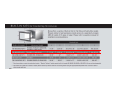
VG 232–232CA
Equipped for natural gas. Jets
supplied for conversion to LP gas.
– Special appliances from the
professional kitchen. Individually
put together with continuous
aluminum control panel.
– Electric ignition of all burners.
Simply press the knob, turn it and
hold it there until a stable flame
burns.
Gas cooktop with integrated
control panel
Width 11 15 /16 " (29 cm)
Series 200
Brushed stainless steel cooktop.
VG 232–232 CA
Two gas burners suitable for pots
up to max. ∅ 8 11 /16 " cm : One
high-output burner (9,500 BTU).
755–
Natural gas
One standard burner (6,500 BTU).
120V / 60Hz
Electric ignition.
One-hand operation.
Cast-iron holder, also suitable for
small pots.
Enameled burner cap.
All-gas valve with fine control and
thermoelectric safety pilot.
Optional accessories :
125–
VD 201–010 Shot-blasted
aluminum appliance cover. Cast
iron grates must be removed
before cover can be closed.
50–
VV 200–000 Connecting strip for
combination with other appliances
with integrated control panel.
Order cover separately.
Planning notes:
The gas cooktop is equipped
with a connecting cable and a
shock-proof plug (55").
When used with downdraft VL 051
swivel range is not going over the
gas cooktop.
A minimum clearance of 4" from
adjacent heat-sensitive furniture
or contact surfaces must be
observed or thermal insulation
must be installed.
Appliance clicks into place
when inserted in the work top
from above.
Maximum drawer depth16 1 /2 ".
Total rating : 16,000 BTU
Total Amps: 1
Numbers indicated
inside parenthesis (
56
) = mm
VC 230–613
– Special appliances from the
professional kitchen. Individually
put together with continuous
aluminum control panel.
– Two cooking zones including
combination. Output up to 1800 W.
Two cooking zones:
Vario Glass ceramic cooktop
with integrated control panel
One Super Quick cooking zone
∅ 5 11 /16 " (1200 W).
Width: 12" (29 cm)
One Super Quick cooking zone
∅ 4 3 /4 " (700 W), converts to
∅ 7 1 /16 " (1800 W).
Series 200
VC 230–613
845–
220-240V / 60Hz
Two continuously variable energy
controls.
Cooking zone marking.
Individual residual heat display.
Operation indicator light.
Optional accessories :
50–
VV 200–000 Connecting strip for
combination with other appliances
with integrated control panel.
125–
VD 201–010 Shot-blasted
aluminum appliance cover.
125–
SH 230–001 Hinge holder
required for fitting the
appliance cover.
Planning notes:
Appliance clicks into place
when inserted in the countertop
from above.
The cooktop is equipped with a
67" connecting cable
(hardware required).
Total rating : 3.0 kW
(8.5)
5 ⁄16"
Total Amps: 13
(288)
11 5 ⁄16"
(510)
20 1 ⁄16"
(1.7 m) (33)
67" 1 5 ⁄16"
(75)
2 1 5 ⁄16"
min. (35)
min. 1 3 ⁄8"
2 3 ⁄16"
(56)
19 5 ⁄16"
(490)
min. 1 1 5 ⁄16"
min. (50)
Numbers indicated
inside parenthesis (
10 9 ⁄16"
(268)
) = mm
54
VL 051–707
– Ventilation element raises out of
the cooktop. The most spectacular
ventilation method around.
– Effective extraction at the
countertop level. Your head
will stay free of cooking vapors
as well.
– More head room. Gives you
more space over the cooking area.
Power controlled by 3-stage
switch.
Telescopic swivel downdraft
ventilation system
Width 6
11 /16 "
10 minute after-running mode
on setting 1.
(17 cm)
Series 200
Grease filter saturation display.
Stainless steel with aluminum
control panel
Metal grease filter, dishwashersafe.
Sensor jam protection.
For combination with the fan
unit GB 031-707.
VL 051–707
_
Child safety lock.
1,590–
Ventilation element for installation
between two cooktops or special
built-in appliances with integrated
control panel.
120V / 60Hz
Especially recommended between
glass ceramic cooktop and barbecue grill, deep fryer or steamer.
Output increased by means of
a three-stage switch.
Automatically rises to grilling
position (2 1 /4 " above cooktop)
and cooking position (15 3 /4 "
above cooktop).
10-minute continued running
stage in stage 1.
Grease filter saturation indicator.
Metal grease filter grill can be
washed out, dishwasher-safe.
Infinitely variable height adjustment between the high and low
positions by control.
In the cooking position, the arm
can be swivelled manually by
± 90° swiveled.
When the VL 051 is switched to
the descent mode, the swivel arm
automatically returns to the
middle position.
5" pipe connection.
Optional accessories :
_
45–
VV 200-000 Connecting strip
for combination with other
appliances with integrated
control panels.
Planning notes:
Minimum countertop height 36".
Recess the base area in the
base cabinet underneath the VL
(see sketch).
For combination with remote fan
motor GB 031-707.
Plan an Aluflex exhaust air pipe,
ø 5 ", to the remote fan motor.
Do not install next to wok VG 231.
Not for installation in the area of
drawers. Observe the maximum
extending height of 15 3 /4 " swivel
range ± 90° in this position.
Limit the swivel range above gas
appliances (VG, KG).
See installation specifications for
details. Length of connecting
cable with plug: 30".
Numbers indicated
inside parenthesis (
) = mm
99
Montageanleitung
Notice d’installation
Installation Instructions
Montageaanwijzing
Istruzione per il montaggio
Instrucciones de montaje
VV 200-000
Monteringsanvisning
Monteringsvejledning
Monteringsanvisning
Asennusohjeet
Οδηγίες εγκατάστασης
Инструкция по монтажу
Instrukcja instalacyjna
Instruções de montagem
Montaj talimatları
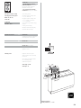
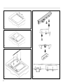
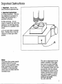
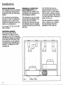
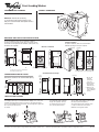
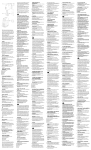
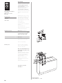
Installing with two Vario appliances
When you use the VV 200-000 connecting trim,
several Vario appliances can be installed together.
Proceed as follows when installing:
Produce the recess for one or several Vario
appliance(s) in your worktop.
Mark the distance from the centre of the appliance
and secure the appliance rails (Fig. 1).
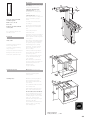
Lower the first appliance into the worktop.
Place the second appliance on the springs and
check the distance between the control panels:
this must be between 4.5 and 5.0 mm (Fig. 2).
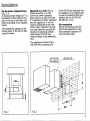
If the distance is not exactly right, take out the
second appliance again and loosen the screws of
the installation rails. You can now move the rails in
the oblong holes. Then tighten the screws again.
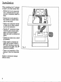
Press the second appliance into the rails.
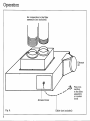
Place the VV 200-000 connecting trim between
the appliances and press them in at the front first
(Fig. 3).
In certain combinations of appliances (especially
with the KG 260), the gap between the appliance
and the connecting trim may be too much. In this
case, use the included clamping piece (Fig. 4).
To this end, screw in the two included screws to
1.2 mm. Press in the trim between the appliances.
Then push the clamping piece onto the two screws
from below.
Tighten the two screws on the clamping piece until
the connecting trim is flush with the appliance.
Important:
The specified dimensions apply to the installation
of two Vario appliances. When combining with
other appliances, please use the dimensions
specified in the type list.
Het inbouwen van twee
Vario-apparaten
Met behulp van de verbindingsstrip VV 200-000
kunt u meerdere Vario-apparaten naast elkaar
inbouwen. Ga dan als volgt te werk:
Maak de uitsparing in het werkblad voor de
desbetreffende apparaten. Markeer de afstand
tot het midden van het apparaat en monteer de
profielen (afbeelding 1).
Plaats het eerste apparaat in het werkblad. Leg het
tweede apparaat op de klemveren en controleer de
afstand tussen de bedieningspanelen. Deze dient
4,5 tot 5,0 mm te zijn (afbeelding 2).
Mocht de afstand niet juist zijn, haal het tweede
apparaat dan weer weg en draai de schroeven van
de inbouwprofielen iets losser. U kunt de profielen
nu nog iets verschuiven. Draai de schroeven daarna
weer aan. Druk nu ook het tweede apparaat in de
profielen.
Plaats de verbindingsstrip VV 200-000 tussen de
twee apparaten. Druk deze er eerst aan de
voorkant in (afbeelding 3).
Bij bepaalde combinaties (in het bijzonder met
KG 260) kan de spleet tussen het apparaat en de
verbindingsstrip te groot worden. Gebruik in dat
geval het bijgevoegde klemelement (afbeelding 4).
Draai hiertoe de twee bijgevoegde schroeven er tot
op 1,2 mm na in. Druk de verbindingslijst tussen de
apparaten. Schuif vervolgens het klemstuk van
onderen op de twee schroeven.
Draai de twee schroeven van het klemelement aan
totdat de verbindingsstrip strak op het apparaat
aansluit.
Belangrijk!
De aangegeven maten gelden voor het inbouwen
van twee Vario-apparaten. Bij combinaties met
andere apparaten dient u de afmetingen uit de
typelijst aan te houden.
5
1
2
3
6
4
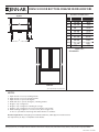
EB 270/271–...
Planning notes:
4' Power cable (hardwire required).
Hinging must be specified when
ordering as the door is not
interchangeable.
Universal heating system with
ten heating methods.
Oven interior volume: 2.4 cb.ft.
When planning a corner solution,
pay attention to the 90° door
opening angle.
– Large control panel with display.
The tailored partner for the Combi
steam oven.
– 10 heating methods with baking
stone/roaster function and
rotisserie. For almost all cooking
methods including a brick oven
and international dish preparation.
Single oven
EB 270pi
Gaggenau 200 Series
Pyrolytic self-cleaning system
Plan a minimum distance of 2"
between two ovens installed
side by side when handles in the
middle – or 3 ⁄ 4 " when centered
around hinged sides.
– Exact temperatures thanks to
electronic control and temperature
probe. Stress-free cooking for and
with guests.
Width 24" (60 cm)
220-240V / 60Hz
Depth of handle: 3 3 ⁄ 8 ".
Right-hinged
EB 270–600
2,540–
Stainless steel
Electronic precision temperature
control between 120°F – 570°F,
from 120°F – 170°F in 5°F
increments and from 170°F– 570°F
in 10°F increments.
EB 270–630
100 W halogen lighting.
Aluminum
Super Quick preheating.
Anthracite
EB 270–610
2,740–
Total rating: 3.7 kW
Total Amps: 16
Large function display.
Left-hinged
EB 271–600
Automatic cooking timer.
2,540–
Anthracite
EB 271–610
Actual temperature display:
“Thermo Test”.
2,740–
Stainless steel
EB 271–630
Aluminum
Meat probe programmable with
digital read out from 85°F to
210°F and automatic shut-off
function.
one broil pan, temperature probe,
Universal heating system with
the following heating modes.
Economy program.
Proofing.
Baking stone socket.
Rotisserie rotary spit.
rotary spit.
Smart pyrolytic self-cleaning.
Accessories included in the price:
One wire rack, one baking tray,
Porcelain interior.
Catalyst for air cleaning.
Cooled housing.
Minimum distance of 4"
between wall and appliance
to allow full opening of door.
Heat-insulated door with
four-fold glazing.
Child and vacation lock.
Glass door opening through 180°.
KB 110–046 Glass tray.
Optional accessories
200–
PS 026–001 Baking stone with
pizza spatula, without heating element.
270–
BT 026–001 Cast roaster, without
heating element.
75–
HZ 026–001 Heating element for
baking stone and cast roaster.
See page 13 for accessories.
Numbers indicated
inside parenthesis (
10
) = mm
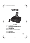
FRENCH DOOR BOTTOM-FREEZER REFRIGERATORS
PRODUCT DIMENSIONS
Top View
INCHES
B
A
A
C
B
D
1
C
D2
E3
E
F4
G5
F
H6
J7
CENTIMETERS
35 5/8
28 7/8
24
26 3/4
43 1/4
40 1/8
68 5/8
70 1/8
N/A
90.5
73.3
61.0
67.9
109.9
101.9
174.3
178.1
N/A
MODEL SKUs
JFC2089HES
J G
H
Front View
Style of product may vary from picture
NOTES:
1.
2.
3.
4.
5.
6.
7.
8.
Depth with doors closed, including handle.
Depth with doors closed, excluding handle.
Depth with doors open at 90 degrees.
Width with doors open at 90 degrees, including handles.
Height to top of refrigerator
Height to top of refrigerator including door hinge.
Height to top of refrigerator door trim (if needed for trim models).
When installing refrigerator in or near a corner, allow enough room
for door to open without interfering with cabinet drawers or hardware.
Electrical requirements: Adequately wired individual 120V A/C, 60Hz approved electrical circuit.
Use required fuse (15 amp) or comparable circuit breaker.
Important:Because of continuing product improvements, Jenn-Air reserves the right to change specifications without notice. Dimensional specifications are provided for
planning purposes only. For complete details see installation instructions that accompany each product before selecting cabinetry, making cutouts or beginning installation.
2005-12-30 at 11:20:16 CST
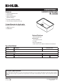
PRO TASKCENTERTM
Features
•
•
•
•
•
•
SINK
K-3326
18 gauge stainless steel
Flush-mount
Double compartment with smaller disposal basin
3-hole
Includes installation hardware
60″ (152.4 cm) x 25-3/4″ (65.4 cm)
Codes/Standards Applicable
Specified model meets or exceeds the following:
• ASME A112.19.3
• IAPMO/UPC
• CSA B45
Colors/Finishes
• NA: None applicable
Accessories:
• CP: Polished Chrome
• ST: Stainless Steel
Specified Model
Model
K-3326R-3
K-3326L-3
Description
3-hole sink with drainboard on right
3-hole sink with drainboard on left
Colors/Finishes
❑ NA
❑ NA
Recommended Accessories
K-6330
ProMasterTM faucet
K-9000
P-Trap (2 traps recommended)
❑ CP
❑ CP
Available Accessories
K-2989
Countertop cutting board
K-8813
Stainless steel strainer with tailpiece
❑ NA
❑ CP
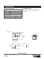
Product Specification
The flush-mount sink shall be 60″ (152.4 cm) in length and 25-3/4″ (65.4 cm) in width. Sink shall be 3-hole drilling. Sink shall
be made of 18 gauge stainless steel. Sink shall feature a double compartment with a smaller disposal basin. Sink shall include
installation hardware. Sink shall be Kohler Model K-3326-____-____.
Page 1 of 2
86563-4-AD
USA: 1-800-4-KOHLER
Canada: 1-800-964-5590
kohler.com
PRO TASKCENTERTM
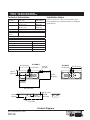
Technical Information
Installation Notes
Install this product according to the installation guide.
Fixture*:
Sink
Disposal
Basin area
Water depth
21″ (53.3 cm) x
9-1/4″
18″ (45.7 cm)
(23.5 cm)
11″ (27.9 cm) x
5-1/4″
18″ (45.7 cm)
(13.3 cm)
21″ (53.3 cm) x 18″ (45.7 cm)
3-5/8″ (9.2 cm) D.
1-3/8″ (3.5 cm) D.
For the disposal unit, consult the supplier for roughing-in
measurements.
Drainboard
Drain holes
Faucet
holes
* Approximate measurements for comparison only.
Included components:
Installation hardware
Cutting board
Wire rack
Wire basket
Basin accessory
87357
87365
87366
87360
87367-96
K-3326R-3
30" (76.2 cm)
4" (10.2 cm)
K-3326L-3
4" (10.2 cm)
2-11/16"
(6.8 cm)
4-1/4"
(10.8 cm)
14-1/4"
(36.2 cm)
25-3/4"
(65.4 cm)
17-15/16"
(45.6 cm)
60" (152.4 cm)
1-5/8" (4.1 cm)
10-1/4"
(26 cm)
6-1/4"
(15.9 cm)
15-5/8"
(39.7 cm)
1-1/2" OD
Product Diagram
PRO TASKCENTERTM SINK
Page 2 of 2
86563-4-AD
30" (76.2 cm)
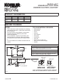
UNDERTONETM
Features
•
•
•
•
•
•
UNDERCOUNTER SINK
K-3334
18 gauge stainless steel
Undercounter
Single compartment
Squared bowl(s)
Includes installation hardware
14″ (35.6 cm) x 18-5/8″ (47.3 cm)
Codes/Standards Applicable
Specified model meets or exceeds the following:
• ASME A112.19.3
• IAPMO/UPC
Colors/Finishes
• NA: None applicable
Accessories:
• CP: Polished Chrome
• 0: White
• NA: None applicable
• Other: Refer to Price Book for additional colors/finishes
Specified Model
Model
K-3334
Description
Undercounter sink
Optional Accessories
K-2989
Countertop cutting board
K-3277
Wire basket
K-8801
Duostrainer® sink strainer
Colors/Finishes
❑ NA
❑ NA
❑ 0 White
❑ CP
❑ Other
❑ Other
Product Specification
The undercounter sink shall be 14″ (35.6 cm) in length and 18-5/8″ (47.3 cm) in width. Sink shall be made of 18 gauge stainless
steel. Sink shall be single compartment with squared bowl. Sink shall include installation hardware. Sink shall be Kohler Model
K-3334.
Page 1 of 2
111138-4-AB
USA: 1-800-4-KOHLER
Canada: 1-800-964-5590
kohler.com
UNDERTONETM
Technical Information
Installation Notes
Install this product according to the installation guide.
Fixture*:
Basin area
14″ (35.6 cm) x 18-5/8″ (47.3 cm)
Water depth
7-7/16″ (18.9 cm)
Drain hole
3-5/8″ (9.2 cm) D.
*Approximate measurements for comparison only.
Included components:
Hardware kit
Cut-out template
Allow a minimum of 2″ (5.1 cm) clearance around sink rim for
clip attachment.
91915
113195-7
1-3/4" (4.4 cm) R.
7/8" (2.2 cm)
Countertop
7-7/8"
(20 cm)
20-3/8"
(51.8 cm)
Sink
Clip
2" (5.1 cm) Min
15-3/4" (40 cm)
13"
(33 cm)
7-5/8"
(20 cm)
1-1/2" OD
Product Diagram
UNDERTONETM UNDERCOUNTER SINK
Page 2 of 2
111138-4-AB
MAN’S LAV
ENAMELED CAST IRON
UNDERCOUNTER LAVATORY
PRODUCT INFORMATION
Fixture*:
basin area
water depth
Lavatory
24” x 13”
4-1/4”
Outlet
1-11/16” D.
* Approximate measurements for comparison only.
BEFORE YOU BEGIN
NOTES
TOOLS AND MATERIALS REQUIRED
These instructions contain important care, cleaning,
and warranty information – please leave instructions
for the consumer.
Due to the nature of the installation, undercounter
lavatories should be installed by trained and
experienced installers.
Prior to installation, unpack the new lavatory and
carefully inspect it for damage. Return the lavatory
to its protective carton until you are ready to install
it.
Do not use adhesives or adhesive sealants with this
product.
4” 4”
Safety glasses
Safety shoes
Pencil
Scissors
Tape measure
Putty knife
Screwdriver
Hole saw
Keyhole saw or saber saw
Drill (1/2” dia. drill bit or larger)
Sealant
Roughing-In Notes
2-5/16”
Fixture dimensions are nominal and conform to tolerances in ASME/ANSI Standard A112.19.1M.
7-5/8”
( T ) Pop-up drain 13-1/2”.
19”
( S ) 10” (Based on 12” riser which may require cutting).
Holes in undercounter fixture are oversized. Drill fitting
holes in counter according to fitting rough-in.
14”
28”
(T)
1/2”
SEALANT
3/8” D.
7-7/8”
(S)
SEALANT
5/8”
3/8” COLD
3/8” HOT
4” 4”
LAVATORY
MARBLE SLAB
INSTALLATION
1-1/4” OUTLET
NOTE: WATERPROOF UNPROTECTED OVERHANG
AREA ON THE UNDERSIDE OF WOOD COUNTER
.9<116
114408-2-CB
LAVATORY
WOOD COUNTER
INSTALLATION
2000 Kohler Co.
INSTALLATION
NOTE: "% $(' %! '*! '
&#& (' +'(% ! !'
Cut out the template and mounting hole locations with a
scissors inside the cutting line, as shown.
Fig. #1
% ' ' #' "! ' "(!'%'"# (&! &"' #! !'%!& % #%") '" # ! '
"#!!
Fig. #2
"' ' (' " !'%! "! ' "(!'%'"#
''!&
Fig. #3
(' "(' ' "#!! , %(, ""*! ' #! !
'% %" ' ' #'
#"%%, # ' )'"%, ! ' "(!'%'"# ('"(' '"
"% '
& * &%) & ( "% ##,! &!'
") ' )'"%, %"
' "(!'%'"# ('"('
Fig. #4
% ' (' "& (' "& (&' #%'
! '*! - ! - ! '% "% "%
)'"%, ('&
!&' ' (' '" ' "(!'%'"# ""*! '
!('(%%& !&'%('"!&
114408-2-CB
2
Kohler Co., Kohler, WI
marble or solid surface countertops upside down on
foam padding. Drill 3/8” diameter holes, 5/8” deep in the
locations shown. Set the lead anchors into the holes using
a setting tool. Tap the setting tool with a hammer to set the
lead anchors into position.
SEALANT
SEALANT
3/8” D.
5/8”
NOTE: The insert must be properly installed to ensure
proper fit.
LAVATORY
MARBLE SLAB
INSTALLATION
NOTE: For wood countertops, pre-drill the holes for wood
screws in the locations shown. Waterproof any
unprotected areas of wood.
LAVATORY
WOOD COUNTER
INSTALLATION
Fig. #5
Follow the instructions listed on the sealant label. Allow
the sealant to set for 30 minutes or longer. Connect the
drain fittings and faucet supply fittings. Turn on the water,
and check for leaks at all the connections.
Fig. #6
PARTS INFORMATION
ITEM
NO.
1
2
3
4
PART
NO.
44596
44597
68918
44598
1
DESCRIPTION
Insert
Clip
Screw
Screw
2
4
114408-2-CB
3
2
3
Kohler Co., Kohler WI
IMPORTANT CONSUMER INFORMATION
CLEANING YOUR CAST IRON LAVATORY
Quality Kohler enamel is fused to red-hot cast iron. The
resulting glass-hard surface and lustrous depth of color is
beautiful to look at, easy to care for, and more resistant to
scratching than plastic materials. As with any smooth
surface, avoid using abrasive cleansers on your cast
iron lavatory. Abrasive cleansers will scratch and dull the
surface.
To obtain warranty service, contact Kohler Co. through your
Dealer or Plumbing Contractor, or by writing: Kohler Co., Attn:
Customer Service Department, 444 Highland Drive, Kohler, WI
53044, USA, or by calling 1–800–4–KOHLER from within the
USA,
1–800–964–5590
from
within
Canada,
or
001–877–680–1310 from within Mexico. Please be sure to
provide all pertinent information regarding your claim, including
a complete description of the problem, the product, model
number, color and the date the product was purchased. Also
include the name of your contractor or distributor and your
original invoice.
REQUESTING SERVICE
Please take a moment to familiarize yourself with the Kohler
Warranty, its benefits, and limitations. Kohler Co. and its
distributors support you with one of the largest Service Networks
of its type. Here’s what you need to do if you require service:
FIRST:
Contact the dealer or contractor who sold and
installed the product. They should be able to solve
any problems you may have.
SECOND: If your dealer or contractor cannot solve the
problem, they will contact or supply you with the
name of the local Kohler Distributor and the:
If the product is used commercially, Kohler warrants the product
to be free from defects in material and workmanship for one (1)
year from the date of purchase as shown on the invoice or
receipt with all other terms of this warranty applying except
duration.
Any implied warranties for product used
commercially, including that of merchantability or fitness
for a particular purpose, are expressly limited in duration to
the duration of the one year express warranty.
KOHLER TECHNICAL SPECIALIST
THIRD:
If you are unable to obtain warranty service through
either your contractor or Kohler Co. distributor,
please write us directly at Kohler Co., Attn:
Customer Service Department, Kohler, WI 53044
U.S.A.
FOURTH:
Include all pertinent information regarding your
claim, including a complete description of the
product, model numbers, colors, finishes, and the
date the product was installed. Include a
description of the problem, and a photocopy of your
invoice for the products involved. Also give us the
name of the contractor and distributor.
To the extent permitted by law, Kohler Co. disclaims all
implied warranties including merchantability and fitness
for a particular purpose. Kohler Co. disclaims any liability
for special, incidental, or consequential damages. Some
states/provinces do not allow limitations on how long an implied
warranty lasts or the exclusion or limitation of special, incidental,
or consequential damages, so these limitations and exclusions
may not apply to you. This warranty gives you specific legal
rights. You may also have other rights which vary from
state/province to state/province. This warranty is to the original
purchaser only and excludes product damage due to installation
error, product abuse, or product misuse, whether performed by
a contractor, service company, or yourself. This warranty
applies only for Kohler cast iron product installed in the United
States of America, Canada and Mexico.
LIFETIME LIMITED WARRANTY – CAST IRON
Kohler warrants this cast iron product to be free of defects in
material and workmanship during normal residential use for as
long as the original purchaser owns his/her home. Gloss
reduction, scratching, staining or alkaline etching, of the finish
over time due to use, cleaning practices or water or atmospheric
conditions are not manufacturing defects but are indicative of
normal wear and tear. This warranty is applicable to Kohler cast
iron product manufactured after February 10, 2000.
This is our exclusive written warranty.
If a defect is found in normal residential use, Kohler Co. will, at
its election, repair, replace or make appropriate adjustment.
Damage caused by accident, misuse, or abuse is not covered
by this warranty. Improper care and cleaning will void the
warranty. Proof of purchase (original sales receipt) must be
provided to Kohler with all warranty claims. Kohler Co. is not
responsible for labor charges, installation, or other
consequential costs. In no event shall the responsibility of
Kohler exceed the purchase price of the product.
114408-2-CB
4
Kohler Co., Kohler, WI
®
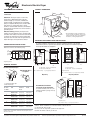
Front Loading Washer
PRODUCT MODEL NUMBERS
OVERALL DIMENSIONS
27"
(68.6 cm)
50¹⁄₄"
(127.6 cm)
WFW8500S
Electrical: 120-volt, 60 Hz, AC-only,
15- or 20-amp, fused electrical supply. A timedelay fuse or circuit breaker and separate circuit is
recommended.
36"
(91.4 cm)
30¹⁄₂"
(77.5 cm)
RECESSED AREA AND CLOSET INSTALLATIONS
Recommended installation spacing for
cabinet installation
For cabinet installation, with a door, the minimum
ventilation openings in the top are required.
For closet installation, with a door, the minimum ventilation
openings in the top and bottom of the door are required (view 2).
Louvered doors with equivalent air ventilation openings in the top
and bottom are acceptable.
Washer on Pedestal
3"
(7.6 cm)
48"
(122 cm)
48 in.2
(310 cm 2)
7" (17.8 cm)
7" (17.8 cm)
38" min.
(96.5 cm)
9"
(22.9 cm)
24 in.2
(155 cm 2)
3"
(7.6 cm)
1"
30¹⁄₂"
4"
(2.5 cm) (77.5 cm) (10.2 cm)
A
1"
(2.5 cm)
B
1"
(2.5 cm)
27"
(68.6 cm)
1"
(2.5 cm)
30¹⁄₂"
4"
(77.5 cm) (10.2 cm)
A. Side view - closet or confined area
B. Closet door with vents
4"
31¹⁄₂"
1"
(10.2 cm) (80.0 cm) (2.5 cm)
Stacked Washer and Dryer
UNDERCOUNTER INSTALLATION
Dimensions shown are the recommended spacing.
48" 2 *
(310 cm2)
12" (30.5 cm)
*Min. top and
bottom air
openings for
closet door.
**External exhaust
elbow requires
additional space.
***Wall, door and
floor molding may
require additional
spacing.
3" (7.6 cm)
2" (5 cm)
72"
(182.9 cm)
36" min.
(91.4 cm)
3" (7.6 cm)
1"
(2.5 cm)
24" 2 *
(155 cm2)
1"
(2.5 cm)
27"
(68.6 cm)
1"
27"
1"
(2.5 cm) (68.6 cm) (2.5 cm)
5 ¹⁄₄"**
(13.3 cm)
1" (2.5 cm)
1"***
(2.5 cm)
1"***
(2.5 cm)
27"
(68.6 cm)
DRAIN SYSTEM OPTIONS
Standpipe drain system - wall or floor (view A & B)
The standpipe drain requires a minimum diameter standpipe of 2” (5 cm). The
minimum carry-away capacity can be no less than 17 gal. (64 L) per minute.
The top of the standpipe must be at least 30” (76.2 cm) high and no higher than
96 in. (2.4 m) from the bottom of
the washer.
Floor drain system (view B)
The floor drain system requires a siphon break
that may be purchased separately.
The siphon break must be a minimum of 28”
(71 cm) from the bottom of the washer.
Additional hoses might be needed.
Laundry tub drain system (view A)
The laundry tub needs a minimum
20 gal. (76 L) capacity. The top of
the laundry tub must be at least
30” (76.2 cm) above the floor.
30" min.
(76.2 cm)
30" min.
(76.2 cm)
A
B
Because Whirlpool Corporation policy includes a continuous commitment to improve
our products, we reserve the right to change materials and specifications without notice.
A
26" min.
(66 cm)
B
Dimensions are for planning purposes only. For complete details, see Installation
Instructions packed with product. Specifications subject to change without notice.
Ref. 8540321
06-26-06
®
Electronic Electric Dryer
PRODUCT MODEL NUMBERS
OVERALL DIMENSIONS
WED8300S
WED8500S
50½"
(128.27 cm)
Electrical: This dryer requires a 3 or 4 wire,
single phase, 120/240 volt, 60 Hz., AC only
electrical supply (or 3 or 4 wire, 120/208 volt
electrical supply, if specified on the serial/rating
plate) on a separate 30-amp circuit, fused on both
sides of the line. A time-delay fuse or circuit
breaker is recommended. Connect to an individual
branch circuit. Do not have a fuse in the neutral or
grounding circuit.
Exhaust venting: Exhaust your dryer to the
outside. Four inch diameter vent is required. Rigid
or flexible metal exhaust vent must be used. Do not
use plastic or metal foil vent. Exhaust outlet hood
must be at least 12 inches from the ground or any
object that may be in the path of the exhaust.
36"
91.4 cm)
*28.65"
(72.77 cm)
* Most installations require a minimum 5¹⁄₂”
(14 cm) clearance behind the dryer for the
exhaust vent with elbow. See Installations
Instructions, “Venting Requirements.”
27"
(68.6 cm)
RECESSED AREA AND CLOSET INSTALLATION
For closet installation, with a door, the minimum ventilation openings in the top and
bottom of the door are required. Louvered doors with equivalent air ventilation openings
in the top and bottom are acceptable.
UNDERCOUNTER INSTALLATION
Dimensions shown are for minimum spacing.
14" max.
(35.6 cm)
2"*
(5 cm)
14" max.
(35.6 cm)
3"
(7.6 cm)
in.2
48
(310 cm 2)
15" min.
(38.1 cm)
15" min.
(38.1 cm)
36" min.
(91.4 cm)
1"*
(2.5 cm)
27"
(68.6 cm)
1"*
(2.5 cm)
24 in.2
(155 cm 2)
3"
(7.6 cm)
*Required spacing
28.65"
1"
5"*
(2.5 cm) (72.77 cm) (12.7 cm)
EXHAUST VENTING
A
Recommended hood styles
Angled hood style is
acceptable.
27"
(68.6 cm)
*Side or bottom venting - 0" (0 cm) spacing is allowed
Dryer on pedestal
7" (17.8 cm)
7" (17.8 cm)
2.5"
(6.4 cm)
4"
(10.2 cm)
A. Louvered hood style
B. Box hood style
Number of
90° turns
or elbows
B
*Required spacing
**Side or bottom venting - 0" (0 cm) spacing is allowed
Dryer only
4"
(10.2 cm)
5"**
28.65"
(72.77 cm) (12.7 cm)
A. Recessed area
B. Side view - closet or confined area
A
4"
(10.2 cm)
1"
1"*
(2.5 cm) (2.5 cm)
A
B
A. Side view - closet or confined area
B. Closet door with vents
B
1"*
2.5 cm)
Type of
vent
Box or
Louvered
hoods
Angled
hoods
0
Rigid metal
Flexible metal
64 ft (20 m)
36 ft (11 m)
58 ft (17.7 m)
28 ft (8.5 m)
1
Rigid metal
Flexible metal
54 ft (16.5 m)
31 ft (9.4 m)
48 ft (14.6 m)
23 ft (7 m)
2
Rigid metal
Flexible metal
44 ft (13.4 m)
27 ft (8.2 m)
38 ft (11.6 m)
19 ft (5.8 m)
3
Rigid metal
Flexible metal
35 ft (10.7 m)
25 ft (7.6 m)
29 ft (8.8 m)
17 ft (5.2 m)
4
Rigid metal
Flexible metal
27 ft (8.2 m)
23 ft (7 m)
21 ft (6.4 m)
15 ft (4.6 m)
NOTE: Side and bottom exhaust installations have a 90° turn
inside the dryer. To determine maximum exhaust length, add one
90° turn to the chart.
Recommended installation
spacing for cabinet installation
9"
(22.9 cm
*R
For cabinet installation, with a door, the
minimum ventilation openings in the top
are required.
28.65" 1"
27"
1"*
1"*
5"**
(12.7 cm) (72.77 cm) (2.5 cm) (2.5 cm) (68.6 cm) (2.5 cm)
*Required spacing
**Side or bottom venting - 0" (0 cm) spacing is allowed
Select the route that will provide the straightest and most direct path
outdoors. Plan the installation to use the fewest number of elbows and turns.
Use the fewest 90° turns possible.
Do not use vent runs longer than specified in vent length chart.
Determine the number of elbows you will need.
Because Whirlpool Corporation policy includes a continuous commitment to improve
our products, we reserve the right to change materials and specifications without notice.
Dimensions are for planning purposes only. For complete details, see Installation
Instructions packed with product. Specifications subject to change without notice.
Ref. 8578899
06-21-06
®
DRYER VENTING SPECIFICATIONS
Table of Contents
DRYER SAFETY ............................................... 1
INSTALLATION REQUIREMENTS.................. 3
Venting Requirements ................................... 4
DRYER INSPECTION AND CLEANING.......... 5
Frequency of Exhaust System Cleaning....... 5
Inspecting the Exhaust System..................... 5
DRYER SAFETY
Your safety and the safety of others are very important.
We have provided many important safety messages in this manual and on your appliance. Always read and obey all safety
messages.
This is the safety alert symbol.
This symbol alerts you to potential hazards that can kill or hurt you and others.
All safety messages will follow the safety alert symbol and either the word “DANGER” or “WARNING.”
These words mean:
DANGER
WARNING
You can be killed or seriously injured if you don't immediately
follow instructions.
You can be killed or seriously injured if you don't follow
instructions.
All safety messages will tell you what the potential hazard is, tell you how to reduce the chance of injury, and tell you what can
happen if the instructions are not followed.
■
If you are installing a gas dryer, it is recommended that the owner post, in a prominent location, instructions for the customer’s use in
the event the customer smells gas. This information should be obtained from your local gas supplier.
■
Post the following warning in a prominent location.
FOR YOUR SAFETY
Do not store or use gasoline or other flammable vapors and liquids in the vicinity of this or any other appliance.
W10100920
WARNING: For your safety, the information in this manual must be followed to minimize
the risk of fire or explosion, or to prevent property damage, personal injury, or death.
– Do not store or use gasoline or other flammable vapors and liquids in the vicinity of this
or any other appliance.
– WHAT TO DO IF YOU SMELL GAS:
• Do not try to light any appliance.
• Do not touch any electrical switch; do not use any phone in your building.
• Clear the room, building, or area of all occupants.
• Immediately call your gas supplier from a neighbor's phone. Follow the gas supplier's
instructions.
• If you cannot reach your gas supplier, call the fire department.
– Installation and service must be performed by a qualified installer, service agency, or
the gas supplier.
In the State of Massachusetts, the following installation instructions apply:
■
■
■
Installations and repairs must be performed by a qualified or licensed contractor, plumber, or gasfitter qualified or licensed by
the State of Massachusetts.
If using a ball valve, it shall be a T-handle type.
A flexible gas connector, when used, must not exceed 3 feet.
IMPORTANT SAFETY INSTRUCTIONS
WARNING: To reduce the risk of fire, electric shock, or injury to persons when using the dryer, follow basic precautions,
including the following:
■
■
■
■
■
■
■
■
Read all instructions before using the dryer.
Do not place items exposed to cooking oils in your dryer.
Items contaminated with cooking oils may contribute to
a chemical reaction that could cause a load to catch fire.
Do not dry articles that have been previously cleaned in,
washed in, soaked in, or spotted with gasoline, drycleaning solvents, or other flammable or explosive
substances as they give off vapors that could ignite or
explode.
Do not allow children to play on or in the dryer. Close
supervision of children is necessary when the dryer is
used near children.
Before the dryer is removed from service or discarded,
remove the door to the drying compartment.
Do not reach into the dryer if the drum is moving.
Do not install or store the dryer where it will be exposed
to the weather.
Do not tamper with controls.
■
■
■
■
■
■
■
Do not repair or replace any part of the dryer or attempt
any servicing unless specifically recommended in this
Use and Care Guide or in published user-repair
instructions that you understand and have the skills to
carry out.
Do not use fabric softeners or products to eliminate static
unless recommended by the manufacturer of the fabric
softener or product.
Do not use heat to dry articles containing foam rubber or
similarly textured rubber-like materials.
Clean lint screen before or after each load.
Keep area around the exhaust opening and adjacent
surrounding areas free from the accumulation of lint, dust,
and dirt.
The interior of the dryer and exhaust vent should be
cleaned periodically by qualified service personnel.
See installation instructions for grounding requirements.
SAVE THESE INSTRUCTIONS
IMPORTANT: The gas installation must conform with local codes, or in the absence of local codes, with the National Fuel Gas
Code, ANSI Z223.1/NFPA 54.
The dryer must be electrically grounded in accordance with local codes, or in the absence of local codes, with the National
Electrical Code, ANSI/NFPA 70.
2
INSTALLATION REQUIREMENTS
WARNING
Local codes and ordinances that exist must also be met. Consult
your local building inspector for more information.
Improper venting can cause moisture and lint to collect
indoors, which may result in:
Moisture damage to woodwork, furniture, paint, wallpaper,
carpets, etc.
Housecleaning problems and health problems.
Fire Hazard
Use a heavy metal vent.
Do not use a plastic vent.
Moisture
Do not use a metal foil vent.
A normal towel load contains some residual water when it is
removed from the washer. The dryer must remove this water and
discharge it from the drum. When the dryer is not exhausted
outside, this moist air will be recirculated through the heating
source, reducing the dryer’s efficiency.
Exhausting moisture into the room can also cause damage to
walls, floors and picture hangers and cause condensation on
windows and walls in cold weather.
Failure to follow these instructions can result in death
or fire.
WARNING: To reduce the risk of fire, this dryer MUST BE
EXHAUSTED OUTDOORS.
NOTE: This guide is intended to aid qualified HVAC or
Architectural Engineers who design single and multi-dryer unit
venting systems for Whirlpool Corporation dryers sold in the
United States. Whirlpool Corporation provides required airflow
and back pressure specifications, measured at the connection
between the vent system and the dryer’s vent pipe, for use in the
design of dryer vent systems. Whirlpool does not design multidryer vent systems, nor does Whirlpool review or provide
approvals for vent systems designed by third-party engineering
firms.
Lint
Even though the dryer is equipped with a lint screen, fine particles
of lint can get through the screen and be exhausted out of the
dryer. Proper venting of the dryer will keep lint from accumulating
in the laundry area.
Heat
In order to remove moisture from the garments in the dryer, heat is
generated to vaporize the water. Exhausting the dryer outdoors
removes excess heat from the laundry area of the building.
Outside Exhaust
The four basic reasons for exhausting a dryer outdoors are
detailed in this section:
1. To meet codes requirements.
2. To remove moisture from laundry area.
3. To avoid lint accumulation in laundry area.
4. To remove excess heat from laundry area.
Codes Requirements
The following codes should be reviewed to ensure dryer vent
systems are in compliance:
1. International Mechanical Code: In the 2000 version, sections
504 and 913.
2. International Fuel Gas Code: In the 2003 version, section 614.
3. UL 2158 Electric Clothes Dryer Standard references venting
requirements in paragraph 7.3.
4. Other sections of these codes may also apply to multi-dryer
vent systems.
There are other codes requiring dryers to be exhausted when
installed in confined spaces where specified clearances from
combustible surfaces cannot be met. See the Installation
Instructions that came with your dryer for spacing requirements.
Central Exhaust System Requirements
The following guidelines should be considered in the design of
any central exhaust system:
■ Exhaust individual dryers to the central exhaust duct system
with proper size vents to assure adequate performance of
each dryer. The dryer has 4" (10.2 cm) exhaust duct
connections. Four inch (10.2 cm) diameter aluminum vent
should be used to connect each dryer to the central vent.
■
Install weighted dampers on each individual dryer exhaust
duct. These dampers may be used for balancing out the
overall duct system.
■
Provide for a maximum of 0.1" (0.25 cm) of water column
vacuum in the central exhaust duct and a maximum of 0.6"
(1.5 cm) of water column back pressure at the connection of
each dryer exhaust vent at any time that the dryer is in
operation. See “Venting Requirements” for instructions on
how to measure water column back pressure.
■
Design the central duct system for sufficient capacity to
handle the maximum number of dryers operated at one time.
■
Consider moisture, lint and air temperature in the design of the
central duct system. Maximum exhaust temperature of the
dryer will not exceed 200°F (93.3°C) when the dryer is
operated according to the instructions provided with the dryer.
■
Provide for periodic inspection and clean-out of lint
accumulated in the central duct system.
3
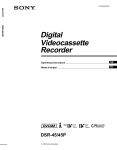
Venting Requirements
Venting systems for Whirlpool dryers must meet the following
requirements:
■ The capacity to handle 150 CFM of air for each dryer in the
system.
■
A back pressure of 0.0" (0 cm) to 0.6" (1.5 cm) of water
column when measured at the connection to the dryer.
Back pressure should be measured with an empty dryer, a clean
lint screen and with the dryer operating in the Air Only cycle (no
heat). Use an inclined manometer, such as Dwyer model 102 (0"2" (0 cm - 5.1 cm] range) or Dwyer model 172 (0"-1" (0 cm 2.5 cm] range) to measure the back pressure. See the following
illustration.
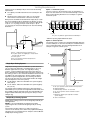
Option 1 - Horizontal System
The most common is the horizontal system, in which banks of
dryers are all located in one room and vented through a common
duct. See the following illustration for an example of a generic
horizontal system.
A
1"*
(2.5 cm)
A. 4" (10.2 cm) diameter rigid metal back draft damper
C
D
B
A
E
A. Dryer - empty and running on Air Only cycle
B. 12" (30.5 cm) min. of straight pipe - measure back
pressure from the center
C. To vent system
D. 0.6" (1.5 cm) water maximum back pressure
E. Inclined manometer
Single Dryer Venting Systems
Single dryer venting systems are defined as systems that have
only one dryer unit attached to a residential-type 4" (10.2 cm)
diameter rigid metal vent system. For single dryer venting
systems, see the Installation Instructions that came with your
dryer to determine the allowable length and number of elbows for
the venting system. In cases where the Installation Instructions do
not address the vent length for the specific number of elbows
required for a particular application, the following calculations
may be used. (The total vent system length includes all straight
and curved portions of the vent system.):
■ For 90° elbows, reduce the allowable vent system length by
10 ft (3.05 m).
■
For 45° elbows, reduce the allowable vent system length by
6 ft (1.83 m).
For example, if the Installation Instructions state that a dryer is
allowed 40 ft (12.2 m) of total vent length with two 90° bends, and
the installation requires three 90° bends, the total allowable vent
length would be reduced by 10 ft (3.0 m) (from 40 ft [12.2 m] to
30 ft [9.1 m)]).
Multiple Dryer Venting Systems
Multiple dryer venting systems must be designed specifically for
each application.
NOTE: It is recommended that an architectural or HVAC
engineering firm be consulted for designing the dryer venting
system.
Connecting a number of dryers to a single vent system is
common in coin-laundry stores and in many apartment buildings.
Listed here are some requirements for examples of three different
multiple dryer venting systems.
4
*Minimum spacing required between dryers
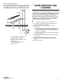
Option 2 - Vertical System
The vertical system is used in some apartment buildings that have
a washer and dryer on each floor. Each dryer is exhausted into the
same central vertical duct. See the following illustration for an
example of a generic vertical system.
D
A
F
E
B
C
F
F
G
A. 0.6" (1.5 cm) water column maximum back pressure
B. Weighted dampers
C. Individual dryer exhaust - on each floor
D. 0.1" (0.25 cm) water column maximum vacuum
E. Main duct
F. Barometric damper (use depends on exhaust
system design)
G. Source of outside air
Option 3 - Combination System
The combination system may be used in high-rise apartments,
with a bank of dryers installed at several different levels. Each of
these banks then exhausts into a central vertical vent. See the
following illustration for an example of a combination system.
DRYER INSPECTION AND
CLEANING
Frequency of Exhaust System Cleaning
A
Every exhaust system must be inspected periodically and cleaned
to ensure that it is intact and free from lint accumulation. The
frequency of these inspections will vary, depending on the system
and usage of the dryer. For single-family usage, an annual
inspection is recommended. In commercial usage or in multiple
dryer systems a more frequent inspection is recommended.
Complaints of long drying times or a hot dryer top indicate the
need for inspection of the exhaust system.
Inspecting the Exhaust System
E
B
C
1. Disconnect the exhaust duct from the dryer and from the
exhaust hood (at the exhaust outlet.)
2. Inspect the interior of the duct and remove any lint
accumulation.
■ Be sure that lint is removed from the exhaust hood. Lint
may collect in the exhaust hood so that the flappers or
louvers (if installed as part of the exhaust system) will not
open or close completely.
■
D
A. Central vertical duct - maximum of 0.1"
(0.25 cm) water column vacuum
B. Weighted damper (each dryer)
C. Maximum of 0.6" (1.5 cm) water column
back pressure
D. Barometric damper (use depends on
exhaust system design)
E. Outside air source
After cleaning the exhaust hood, check that the flapper or
louvers move freely.
3. Reassemble the exhaust duct and hood, checking that the
joints are secure.
4. Operate the dryer and verify that the exhaust air is not
obstructed in the vent and that there are no leaks in the
system.
5. Seal any leaks found.
W10100920
© 2006 Whirlpool Corporation.
All rights reserved.
7/06