1
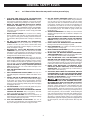
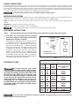
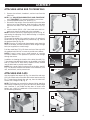
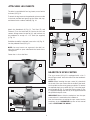
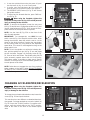
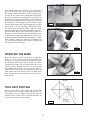
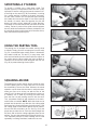
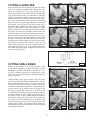
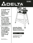
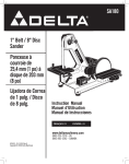
(Model 46-756 and 46-755X)
PART NO. A16528_02-02-06
Copyright © 2006 Delta Machinery
To learn more about DELTA MACHINERY
visit our website at: www.deltamachinery.com.
For Parts, Service, Warranty or other Assistance,
please call
1-800-223-7278 (In Canada call 1-800-463-3582).
INSTRUCTION MANUAL
16” Variable Speed
Wood Lathe
TABLE OF CONTENTS
IMPORTANT SAFETY INSTRUCTIONS . . . . . . . . . . . . . . . . . . . . . . . . . . . . . . . . . . . . . . . . . . . . . . . . . . . . . . . . . . . 2
SAFETY GUIDELINES. . . . . . . . . . . . . . . . . . . . . . . . . . . . . . . . . . . . . . . . . . . . . . . . . . . . . . . . . . . . . . . . . . . . . . . . . 3
GENERAL SAFETY RULES . . . . . . . . . . . . . . . . . . . . . . . . . . . . . . . . . . . . . . . . . . . . . . . . . . . . . . . . . . . . . . . . . . . . 4
ADDITIONAL SPECIFIC SAFETY RULES . . . . . . . . . . . . . . . . . . . . . . . . . . . . . . . . . . . . . . . . . . . . . . . . . . . . . . . . . 5
FUNCTIONAL DESCRIPTION . . . . . . . . . . . . . . . . . . . . . . . . . . . . . . . . . . . . . . . . . . . . . . . . . . . . . . . . . . . . . . . . . . 7
CARTON CONTENTS . . . . . . . . . . . . . . . . . . . . . . . . . . . . . . . . . . . . . . . . . . . . . . . . . . . . . . . . . . . . . . . . . . . . . . . . . 8
ASSEMBLY . . . . . . . . . . . . . . . . . . . . . . . . . . . . . . . . . . . . . . . . . . . . . . . . . . . . . . . . . . . . . . . . . . . . . . . . . . . . . . . . . 9
OPERATION . . . . . . . . . . . . . . . . . . . . . . . . . . . . . . . . . . . . . . . . . . . . . . . . . . . . . . . . . . . . . . . . . . . . . . . . . . . . . . . 14
TROUBLESHOOTING . . . . . . . . . . . . . . . . . . . . . . . . . . . . . . . . . . . . . . . . . . . . . . . . . . . . . . . . . . . . . . . . . . . . . . . 22
MAINTENANCE. . . . . . . . . . . . . . . . . . . . . . . . . . . . . . . . . . . . . . . . . . . . . . . . . . . . . . . . . . . . . . . . . . . . . . . . . . . . . 23
SERVICE . . . . . . . . . . . . . . . . . . . . . . . . . . . . . . . . . . . . . . . . . . . . . . . . . . . . . . . . . . . . . . . . . . . . . . . . . . . . . . . . . . 25
ACCESSORIES . . . . . . . . . . . . . . . . . . . . . . . . . . . . . . . . . . . . . . . . . . . . . . . . . . . . . . . . . . . . . . . . . . . . . . . . . . . . . 26
WARRANTY. . . . . . . . . . . . . . . . . . . . . . . . . . . . . . . . . . . . . . . . . . . . . . . . . . . . . . . . . . . . . . . . . . . . . . . . . . . . . . . . 26
IMPORTANT SAFETY INSTRUCTIONS
Read and understand all warnings and operating instructions before using any tool or equipment.
When using tools or equipment, basic safety precautions should always be followed to reduce the risk of
personal injury. Improper operation, maintenance or modification of tools or equipment could result in serious
injury and property damage. There are certain applications for which tools and equipment are designed. Delta
Machinery strongly recommends that this product NOT be modified and/or used for any application other than
for which it was designed.
If you have any questions relative to its application DO NOT use the product until you have written Delta Machinery
and we have advised you.
Online contact form at www.deltamachinery.com
Postal Mail: Technical Service Manager
Delta Machinery
4825 Highway 45 North
Jackson, TN 38305
(IN CANADA: 125 Mural St. Suite 300, Richmond Hill, ON, L4B 1M4)
Information regarding the safe and proper operation of this tool is available from the following sources:
Power Tool Institute
1300 Sumner Avenue, Cleveland, OH 44115-2851
www.powertoolinstitute.org
National Safety Council
1121 Spring Lake Drive, Itasca, IL 60143-3201
American National Standards Institute, 25 West 43rd Street, 4 floor, New York, NY 10036 www.ansi.org
ANSI 01.1Safety Requirements for Woodworking Machines, and the U.S. Department of Labor regulations www.osha.gov
SAVE THESE INSTRUCTIONS!
2
SAFETY GUIDELINES - DEFINITIONS
It is important for you to read and understand this manual. The information it contains relates to
protecting YOUR SAFETY and PREVENTING PROBLEMS. The symbols below are used to help you
recognize this information.
Indicates an imminently hazardous situation which, if not avoided, will result in death or
serious injury.
Indicates a potentially hazardous situation which, if not avoided, could result in death or serious
injury.
Indicates a potentially hazardous situation which, if not avoided, may result in minor or moderate
injury.
Used without the safety alert symbol indicates potentially hazardous situation which, if not
avoided, may result in property damage.
CALIFORNIA PROPOSITION 65
Some dust created by power sanding, sawing, grinding, drilling, and other construction activities
contains chemicals known to cause cancer, birth defects or other reproductive harm. Some examples of these
chemicals are:
• lead from lead-based paints,
• crystalline silica from bricks and cement and other masonry products, and
• arsenic and chromium from chemically-treated lumber.
Your risk from these exposures varies, depending on how often you do this type of work. To reduce your
exposure to these chemicals: work in a well ventilated area, and work with approved safety equipment, always
wear NIOSH/OSHA approved, properly fitting face mask or respirator when using such tools.
3
GENERAL SAFETY RULES
Failure to follow these rules may result in serious personal injury.
1.
2.
3.
4.
5.
6.
7.
8.
9.
10.
11.
12.
13.
14. USE THE PROPER EXTENSION CORD. Make sure your
extension cord is in good condition. When using an extension
cord, be sure to use one heavy enough to carry the current
your product will draw. An undersized cord will cause a drop
in line voltage, resulting in loss of power and overheating. See
the Extension Cord Chart for the correct size depending on
the cord length and nameplate ampere rating. If in doubt, use
the next heavier gauge. The smaller the gauge number, the
heavier the cord.
15. SECURE THE WORKPIECE. Use clamps or a vise to hold the
workpiece when practical. Loss of control of a workpiece can
cause injury.
16. FEED THE WORKPIECE AGAINST THE DIRECTION OF
THE ROTATION OF THE BLADE, CUTTER, OR ABRASIVE
SURFACE. Feeding it from the other direction will cause the
workpiece to be thrown out at high speed.
17. DON’T FORCE THE WORKPIECE ON THE MACHINE.
Damage to the machine and/or injury may result.
18. DON’T OVERREACH. Loss of balance can make you fall into
a working machine, causing injury.
19. NEVER STAND ON THE MACHINE. Injury could occur if the tool
tips, or if you accidentally contact the cutting tool.
20. NEVER LEAVE THE MACHINE RUNNING UNATTENDED.
TURN THE POWER OFF. Don’t leave the machine until it comes
to a complete stop. A child or visitor could be injured.
21. TURN THE MACHINE “OFF”, AND DISCONNECT THE
MACHINE FROM THE POWER SOURCE before installing or
removing accessories, changing cutters, adjusting or changing
set-ups. When making repairs, be sure to lock the start switch
in the “OFF” position. An accidental start-up can cause injury.
22. MAKE YOUR WORKSHOP CHILDPROOF WITH
PADLOCKS, MASTER SWITCHES, OR BY REMOVING
STARTER KEYS. The accidental start-up of a machine by a
child or visitor could cause injury.
23. STAY ALERT, WATCH WHAT YOU ARE DOING, AND USE
COMMON SENSE. DO NOT USE THE MACHINE WHEN
YOU ARE TIRED OR UNDER THE INFLUENCE OF DRUGS,
ALCOHOL, OR MEDICATION. A moment of inattention while
operating power tools may result in injury.
24.
USE OF THIS TOOL CAN GENERATE AND
DISBURSE DUST OR OTHER AIRBORNE PARTICLES,
INCLUDING WOOD DUST, CRYSTALLINE SILICA DUST
AND ASBESTOS DUST. Direct particles away from face
and body. Always operate tool in well ventilated area and
provide for proper dust removal. Use dust collection system
wherever possible. Exposure to the dust may cause serious
and permanent respiratory or other injury, including silicosis (a
serious lung disease), cancer, and death. Avoid breathing the
dust, and avoid prolonged contact with dust. Allowing dust to
get into your mouth or eyes, or lay on your skin may promote
absorption of harmful material. Always use properly fitting
NIOSH/OSHA approved respiratory protection appropriate for
the dust exposure, and wash exposed areas with soap and
water.
FOR YOUR OWN SAFETY, READ THE INSTRUCTION
MANUAL BEFORE OPERATING THE MACHINE. Learning
the machine’s application, limitations, and specific hazards
will greatly minimize the possibility of accidents and injury.
WEAR EYE AND HEARING PROTECTION. ALWAYS
USE SAFETY GLASSES. Everyday eyeglasses are NOT
safety glasses. USE CERTIFIED SAFETY EQUIPMENT.
Eye protection equipment should comply with ANSI Z87.1
standards. Hearing equipment should comply with ANSI
S3.19 standards.
WEAR PROPER APPAREL. Do not wear loose clothing,
gloves, neckties, rings, bracelets, or other jewelry which may
get caught in moving parts. Nonslip protective footwear is
recommended. Wear protective hair covering to contain long
hair.
DO NOT USE THE MACHINE IN A DANGEROUS
ENVIRONMENT. The use of power tools in damp or wet
locations or in rain can cause shock or electrocution. Keep
your work area well-lit to prevent tripping or placing arms,
hands, and fingers in danger.
MAINTAIN ALL TOOLS AND MACHINES IN PEAK
CONDITION. Keep tools sharp and clean for best and safest
performance. Follow instructions for lubricating and changing
accessories. Poorly maintained tools and machines can further
damage the tool or machine and/or cause injury.
CHECK FOR DAMAGED PARTS. Before using the machine,
check for any damaged parts. Check for alignment of moving
parts, binding of moving parts, breakage of parts, and any
other conditions that may affect its operation. A guard or any
other part that is damaged should be properly repaired or
replaced with Delta or factory authorized replacement
parts. Damaged parts can cause further damage to the
machine and/or injury.
KEEP THE WORK AREA CLEAN. Cluttered areas and benches
invite accidents.
KEEP CHILDREN AND VISITORS AWAY. Your shop is a
potentially dangerous environment. Children and visitors can be
injured.
REDUCE THE RISK OF UNINTENTIONAL STARTING. Make
sure that the switch is in the “OFF” position before plugging
in the power cord. In the event of a power failure, move the
switch to the “OFF” position. An accidental start-up can cause
injury. Do not touch the plug’s metal prongs when unplugging
or plugging in the cord.
USE THE GUARDS. Check to see that all guards are in place,
secured, and working correctly to prevent injury.
REMOVE ADJUSTING KEYS AND WRENCHES BEFORE
STARTING THE MACHINE. Tools, scrap pieces, and other
debris can be thrown at high speed, causing injury.
USE THE RIGHT MACHINE. Don’t force a machine or an
attachment to do a job for which it was not designed. Damage
to the machine and/or injury may result.
USE RECOMMENDED ACCESSORIES. The use of
accessories and attachments not recommended by Delta
may cause damage to the machine or injury to the user.
4
ADDITIONAL SAFETY RULES FOR
WOOD LATHES
FAILURE TO FOLLOW THESE RULES MAY RESULT IN SERIOUS INJURY.
1. DO NOT OPERATE THIS MACHINE UNTIL it is assembled and installed according to the instructions.
2. OBTAIN ADVICE from your supervisor, instructor, or
another qualified person if you are not familiar with the
operation of this machine.
3. FOLLOW ALL WIRING CODES and recommended electrical connections.
4. ROUGH CUT THE WORKPIECE as close as possible to
the finished shape before installing it on the faceplate.
5. EXAMINE THE WORKPIECE FOR FLAWS and test glue
joints before mounting the workpiece on machine. DO
NOT mount a split workpiece or one containing a knot.
6. SECURELY FASTEN THE WORKPIECE to the faceplate
prior to faceplate turning. Use the appropriate size faceplate to properly support the workpiece. Do not let the
screw fasteners interfere with the turning tool at the finished dimension of the workpiece.
7. NEVER DRIVE THE WORKPIECE into the drive center
while the drive center is in the headstock. Set the drive
center into the workpiece with a soft mallet prior to installing it on the headstock.
8. SNUG THE TAILSTOCK CENTER against the workpiece
and lock it. Lubricate the tailstock center if it is not a ball
bearing center.
9. PROPERLY ADJUST THE TOOL REST HEIGHT.
10. ADJUST THE TOOL REST so it is as close to the workpiece as possible.
11. TIGHTEN ALL CLAMP LOCKING HANDLES before
operating.
12. ROTATE THE WORKPIECE BY HAND to check clearance before turning the machine “ON”.
13. CLEAR THE LATHE BED OF ALL OBJECTS (tools,
scraps of wood, etc.) before turning the machine “ON”.
14. EXAMINE THE SET-UP CAREFULLY before turning the
machine “ON”.
15. STAND CLEAR, AND KEEP ALL OBSERVERS AND
PASSERSBY clear of rotating path of workpiece to avoid
injury from flying debris.
16. USE THE LOWEST SPEED when starting a new workpiece. NEVER EXCEED recommended speeds.
17. NEVER ADJUST THE TOOL REST while the workpiece is
turning.
18. NEVER LOOSEN THE TAILSTOCK SPINDLE or the tailstock while workpiece is turning.
19. MOVE THE CUTTING TOOL INTO THE WORKPIECE
SLOWLY, and cut small amounts when roughing.
20. REMOVE THE TOOL REST before sanding or polishing.
21. NEVER PERFORM LAYOUT, assembly, or set-up work on
the table/work area when the machine is running.
22. TURN THE MACHINE “OFF” AND DISCONNECT THE
MACHINE from the power source before installing or
removing accessories, before adjusting or changing setups, or when making repairs.
23. TURN THE MACHINE “OFF”, disconnect the machine
from the power source, and clean the table/work area
before leaving the machine. LOCK THE SWITCH IN THE
“OFF” POSITION to prevent unauthorized use.
24. ADDITIONAL INFORMATION regarding the safe and
proper operation of power tools (i.e. a safety video) is
available from the Power Tool Institute, 1300 Sumner
Avenue, Cleveland, OH 44115-2851 (www.powertoolinstitute.com). Information is also available from the
National Safety Council, 1121 Spring Lake Drive, Itasca,
IL 60143-3201. Please refer to the American National
Standards Institute ANSI 01.1 Safety Requirements for
Woodworking Machines and the U.S. Department of
Labor OSHA 1910.213 Regulations.
SAVE THESE INSTRUCTIONS.
Refer to them often
and use them to instruct others.
5
POWER CONNECTIONS
A separate electrical circuit should be used for your machines. This circuit should not be less than #12 wire and should be protected
with a 20 Amp time lag fuse. If an extension cord is used, use only 3-wire extension cords which have 3-prong grounding type plugs
and matching receptacle which will accept the machine’s plug. Before connecting the machine to the power line, make sure the switch
(s) is in the “OFF” position and be sure that the electric current is of the same characteristics as indicated on the machine. All line
connections should make good contact. Running on low voltage will damage the machine.
Do not expose the machine to rain or operate the machine in damp locations.
MOTOR SPECIFICATIONS
Delta Models 46-756 and 46-755X are wired for 230 volt, 50/60 HZ alternating current and provide a no-load spindle speed of 03000 RPM. Before connecting your machine to the power source, place the switch in the “OFF” position.
NOTE: The specifications on the motor will read “230 volt-3 phase”. This is correct and is accomplished with a high frequency
inverter.
IMPORTANT: The motor cannot be run without the inverter.
NOTE: The power supply to the inverter is 230 volt, single phase.
Do not change the input voltage. To do so will cause severe damage to the inverter.
GROUNDING INSTRUCTIONS
This machine must be grounded while in use to protect the operator from electric shock.
3. Grounded, cord-connected machines intended
for use on a supply circuit having a nominal rating
between 150 - 250 volts, inclusive:
If the machine is intended for use on a circuit that has
an outlet that looks like the one illustrated in Fig. C,
the machine will have a grounding plug that looks
like the plug illustrated in Fig. C. Make sure that the
machine is connected to an outlet having the same
configuration as the plug. No adapter is available or
should be used with this machine. If the machine
must be re-connected for use on a different type of
electric circuit, the re-connection should be made
by qualified service personnel. After re-connection,
the machine should comply with the National Electric
Code and all local codes and ordinances.
GROUNDED OUTLET BOX
CURRENT
CARRYING
PRONGS
GROUNDING BLADE
IS LONGEST OF THE 3 BLADES
Fig. C
MINIMUM GAUGE EXTENSION CORD
EXTENSION CORDS
RECOMMENDED SIZES FOR USE WITH STATIONARY ELECTRIC MACHINES
Ampere
Rating
0-6
0-6
0-6
0-6
6-10
6-10
6-10
6-10
10-12
10-12
10-12
10-12
12-16
12-16
12-16
Use proper extension cords. Make
sure your extension cord is in good condition and is a
3-wire extension cord which has a 3-prong grounding
type plug and matching receptacle which will accept
the machine’s plug. When using an extension cord,
be sure to use one heavy enough to carry the current
of the machine. An undersized cord will cause a
drop in line voltage, resulting in loss of power and
overheating. Fig. D-1 shows the correct gauge to
use depending on the cord length. If in doubt, use the
next heavier gauge. The smaller the gauge number,
the heavier the cord.
Volts
240
240
240
240
240
240
240
240
240
240
240
240
240
240
240
Total
Length of
Cord in
Feet
up to 50
50-100
100-200
200-300
up to 50
50-100
100-200
200-300
up to 50
50-100
100-200
200-300
up to 50
50-100
Gauge of Extension
Cord
18 AWG
16 AWG
16 AWG
14 AWG
18 AWG
16 AWG
14 AWG
12 AWG
16 AWG
16 AWG
14 AWG
12 AWG
14 AWG
12 AWG
GREATER THAN 50 FEET NOT RECOMMENDED
Fig. D-1
In all cases, make certain that the receptacle in question is properly grounded. If you are not sure, have a
qualified electrician check the receptacle.
6
FUNCTIONAL DESCRIPTION
FOREWORD
These Delta 16” adjustable speed wood lathes are large capacity machines, designed for industry, commercial shops,
and schools, or wherever a demand exists for continued accuracy and long life through safe, heavy-duty operation.
UNPACKING AND CLEANING
Carefully unpack the machine and all loose items from the shipping container(s). Remove the protective coating from
all unpainted surfaces, especially on the bottom side of the bedways, the clamp plates under the headstock, the tool rest
base, and the tailstock. This coating may be removed with a soft cloth moistened with kerosene (do not use acetone,
gasoline or lacquer thinner for this purpose). After cleaning, cover the top surface of the bed with a good quality paste
wax.
For your own safety, do not connect the machine to the power source until the machine is
pletely assembled, and you read and understand the entire owner's manual.
com-
CARTON CONTENTS
2
1
4
3
5
6
Fig. 4A
1.
2.
3.
4.
5.
6.
9
7
7.
8.
9.
10.
11.
12.
13.
14.
15.
8
10
Fig. 4B
16.
17.
18.
19.
Headstock
Tailstock
Pedestal
Pedestal Base
Tool rest
Lathe Bed
Flange Nut (4)
Button Head Screw (4)
End Cap (2)
Leg Insert (4)
3/8x16 Carriage Bolt (4)
3/8 Washer (8)
3/8 Nut (4)
Knockout Bar
3/8-16 x 3/4"
Hex Head Bolt (16)
3/8" Lock Washer (12)
3/8" Flat Washer (12)
5/32" Hex Wrench
Spindle Wrench
7
11
12
13
15
16
17
18
19
Fig. 4C
14
ASSEMBLY
ATTACHING LATHE BED TO PEDESTALS
1.
Remove the tailstock, headstock, and tool rest from the
lathe bed.
NOTE: See “ADJUSTING HEADSTOCK AND TAILSTOCK”
and “TOOL REST” for removal/installation instructions.
2. Set the pedestals exactly 58” apart (Fig. 5).
3. Because of the weight, use an assistant to place the lathe
bed on top of the pedestals. Align the holes in the lathe
bed with the holes in the tops of the pedestals (A) Fig.
6C.
4. Use the twelve 3/8-16 x 3/4” Hex Head bolts and lockwashers to attach the lathe bed to the pedestals.
NOTE: Level the machine by loosening the jam nut (A) Fig. 6C
and turning the adjusting nut (B). When leveling is complete,
tighten the jam nut (A).
To increase the height of the machine, place a 4" wide hardwood board (A) Fig. 6A between the pedestal (A) Fig. 6B and
the pedestal base (B) Fig. 6B.
NOTE: Place the 4" board under the pedestal, mark where the
holes are located, and drill the holes to allow longer carriage
bolts (not supplied) to come through.
Fold the metal flap (C) Fig. 6D down and out of the way to fill
the pedestal with sand or concrete to provide more ballast.
NOTE: If sand is used, pour a small amount of concrete
or similar material in the pedestal to prevent sand leakage
through the seams.
In addition to showing the location of the bolts (A and B), Fig.
7 also shows that additional ballast can be added in the lathe
bed (C). Steel bars or other heavy material can be inserted
into the lathe bed to provide more weight.
NOTE: Use a good quality furniture wax on the lathe bed (C)
Fig. 7 to allow for smoother movement of the headstock, tool
rest, and tailstock, and to prevent rust.
58"
Fig. 5
Fig. 6A
Fig. 6B
A
A
B
C
B
A
Fig. 6D
Fig. 6C
C
B
ATTACHING END CAPS
Use the supplied hex wrench (B) Fig. 9 to attach the end caps
(A) Fig. 8 to both ends of the lathe with button head screws (A)
Fig. 9. Insert these through the end cap, then the lathe bed.
Secure with a flange nut (B) Fig. 8 .
NOTE: The flange nut can easily be dropped while attaching
the endcap. A metal flap (C) Fig. 6D will catch any fallen flange
nuts. However, if you folded the flap down to insert more
ballast, use a piece of cardboard or other material to cover
the hole during assembly.
A
Fig. 7
A
B
B
A
Fig. 9
Fig. 8
8
ATTACHING LEG INSERTS
B
The lathe is supplied with four leg inserts, one of which
is shown (A) Fig. 10.
To attach the leg inserts to the pedestals, place one side
in the hole provided and gently tap the other side, top,
and bottom with a rubber mallet (B) Fig. 10.
A
Fig. 10
Attach the Headstock (A) Fig. 11, Tool Rest (E), and
Tailstock (F) to the lathe bed (G). Notice the tool and
centers storage areas located at (H), and brackets on
the pedestals to accept a 2 x 12” shelf (not supplied)
(J) Fig. 11.
A
E
F
H
If additional stability is desired, insert a 4 x 4 (A) Fig. 11
into the pedestal base (B) Fig. 11.
H
G
NOTE: You may have to cut a groove in the 4x4”s to
allow the lumber to pass underneath the head of the
carriage bolt.
B
B
C
Fasten the 4 x 4’s to the floor.
J
A
B
C
A
Fig. 11
HEADSTOCK SPUR CENTER
The spur center (A) Fig.12 is equipped with a No. 2
Morse Taper shank. Insert this shank into the headstock
spindle (B).
A
Fig. 12
NOTE: Before inserting the spur center (A), clean both
the shank of the spur center and the inside of the headstock spindle to remove any grease or debris. To remove
the tapered shank spur center (A) Fig. 13 from the headstock spindle (B) Fig. 13, insert the knockout bar (C) Fig.
13 (supplied) through the hole (D) in the opposite end of
the spindle and push it out.
A
D
IMPORTANT: Never drive the workpiece into the spur
center when it is mounted on the headstock.
C
See the instructions on setting the spur center into the
workpiece in the “OPERATION“ section of this manual
under “CENTERING THE WORK.”
B
Fig. 13
9
TAILSTOCK LIVE CENTER
A
D
The tailstock live center (A) Fig. 14, supplied with your
lathe, is equipped with a No. 2 Morse Taper shank.
NOTE: Before inserting the live center, clean both the
shank and the inside of the tailstock to remove any
grease or debris. To remove the live center (A) from the
tailstock spindle (B), insert the knockout bar (C) Fig. 14
(supplied) through the hole (D) in the opposite end of
the spindle and push the center out. Or, fully retract the
spindle with the handwheel to eject the center.
B
C
Fig. 14
ADJUSTING CLAMPS ON THE HEADSTOCK AND TAILSTOCK
The headstock and tailstock can be moved along the lathe bed. A downward push on the handle (A) Fig. 15 (tailstock
shown) locks the mechanism, while an upward movement of the handle releases the securing action. The clamps are
pre-set at the factory. However, should either need adjusting, use an 11/16” wrench (B) Fig. 15 to slightly loosen or
tighten the two nuts (C) Fig. 15 shown here on the tailstock.
NOTE: Tighten or loosen both nuts equally.
NOTE: Clamp the headstock and tailstock firmly while operating the lathe.
TOOL REST
The tool rest (A) and tool rest base (B) are shown in Fig. 16. To position the tool rest on the lathe bed, lift the clamp
handle (C), move the tool rest base and lock it in place by pushing down on the handle (C). To adjust the tool rest (A) for
the correct height, loosen the locking lever (D), move the tool rest (A) up or down and tighten the locking lever (D).
NOTE: The locking lever (D) Fig. 16 can be positioned on the left or right side of the tool rest base (B). To reposition
the tool rest locking lever (D), unscrew the lever counterclockwise. A threaded hole is provided in the left side of tool
rest base (B) to accept the locking lever (D) if desired.
NOTE: Clamp the tool rest firmly while operating the lathe.
A
A
B
B
D
C
Fig. 15
Fig. 16
C
ADJUSTING THE CLAMP ON THE TOOL REST
To adjust the tool rest clamping action, use a 11/16”
wrench to loosen or tighten the single nut (A) Fig. 17.
A
Fig. 17
10
STARTING AND STOPPING THE LATHE
The power switch, located under the red switch cover (B)
Fig. 18 controls the electrical power to the machine. Lift the
switch cover (B) and move the switch up to the “ON” position. To turn the power off, push the switch cover (B) down.
B
Fig. 18 shows the switch with switch cover down in the
“OFF” position. Fig. 19 shows the lathe in the “ON” position
(switch cover(A) up and power switch (B) up).
When the machine is turned off using the
stop button (A) Fig 18A, the spindle will decelerate under
power.
Fig. 18
When the machine is turned off using the
switch cover (A) Fig 19, the spindle will free spin until it
stops.
A
Always use switch cover to PREVENT
entanglement in rotating parts.
DELTA DOES NOT RECOMMEND the use
of any optional brake systems on the lathe. Further, DO
NOT CHANGE OR ADJUST the controller settings that
have been pre-set at the factory.
Fig. 18A
LOCKING THE SWITCH IN THE “OFF” POSITION
IMPORTANT: When the machine is not in use, the switch
should be locked in the “OFF” position to prevent unauthorized use, using a padlock (A) Fig. 20 with a 3/16” diameter
shackle inserted through the holes in the switch plate (C)
Fig. 19.
A
B
A
ACTIVATING THE SPINDLE
Even though power may be going to the adjustable speed
drive, the spindle will not turn until you activate it.
C
Fig. 19
1.
Before activating the spindle, tighten and clear all
clamps, bolts, etc. Turn the workpiece by hand to see
that it clears the tool rest and to make sure that the
spindle lock is in the UNLOCKED position (A) Fig. 21.
2. Prior to activating the spindle, set the speed control
knob (A) Fig. 22 to the “zero” position.
Input voltage must be 200 to 240 single phase.
Other voltages will severely damage the inverter.
3. After turning the power switch on, push the “run” button
(B) Fig. 22. Then slowly turn the knob (A) clockwise to
the desired speed.
NOTE: The numbers in the display multiplied by 10 will indicate the spindle speed.
A
Fig. 21
Fig. 20
4.
5.
To stop the spindle without turning the power off, press
the stop button (C) Fig. 22 on the control panel.
To restart, press the FWD button (B). The spindle will
gradually return to the speed at which it was stopped.
B
6. The REVERSE (REV) button (D) Fig. 22 will reverse
the spindle rotation.
7. To return back to forward direction, press FWD button (E) Fig. 22.
When using the faceplate, tighten the
faceplate locking screw (A) Fig. 23 to avoid personal
injury or damage to the machine.
C
A
D
E
NOTE: To remove the faceplate, loosen the set screw
(A) Fig. 23 two full turns. Engage the spindle lock (C) and
use the supplied wrench (B) Fig. 24 to loosen the faceplate. Remove the face plate from the spindle.
Fig. 22
C
NOTE: Use the chart (B) Fig. 25A on the front of the
door for safe operation.
B
IMPORTANT: For emergencies, use ONLY the red
switch cover (A) Fig. 19 to stop the machine. Also, when
leaving the machine, lower the switch cover to cut the
power to the whole machine. Pressing the stop button
on the control panel only cuts power to the adjustable
speed drive. This control is still energized as long as the
power switch is on.
Fig. 23
NOTE: To lock the spindle or to utilize the indexing feature, pull the spindle lock pin (A) Fig. 25 out and rotate
the pin clockwise. Engage it in the pulley holes (B) Fig.
25, some of which are shown. The spindle pulley has 24
holes accurately spaced around the rim of the pulley.
This feature makes it possible to make evenly spaced
divisions on turnings which could be fluted, grooved, or
to mark places to be drilled.
A
Fig. 24
B
A
NOTE: Delta does not suggest the use of any optional
brake systems on the lathe. Further, DO NOT CHANGE
OR ADJUST the controller settings that have been preset at the factory.
Fig. 25
CHANGING ACCELERATION/DECELERATION
When using the faceplate, tighten the
faceplate locking screw (A) Fig. 23 to avoid personal
injury or damage to the machine.
B
To change the acceleration/deceleration rate, loosen the
screw (A) Fig. 25A and open the door.
This machine has two different acceleration/deceleration speeds. For larger workpieces, move the switch (A)
Fig. 25 B up to the “SLOW” position. For smaller workpieces, move the switch down to the “FAST” position.
Refer to the chart on the front of the variable speed
drive.
A
Fig. 25A
12
A
Fig. 25B
OPERATION
The following directions will give the inexperienced operator a beginning point for common lathe operations. Practice
on scrap material before attempting serious work.
LATHE TOOLS
Standard wood turning tools come in several different
configurations (Fig. 26). The majority of turnings will
require the gouge tool (A) Fig. 26. This round nosed
hollow chisel is used for roughing cuts, cove cuts and
other operations. The skew chisel (B) is a double-ground
flat chisel, with an angled end. This tool is used for
smoothing cylinders, for cutting shoulders, beads, veegrooves, etc. The parting tool (C) is a double-ground
chisel, used for cutting-off, or for making straight
incisions or sizing cuts to any required diameter. The
round nose scraper (D) is used for mostly hollowing
work, while the square-end scraper is mainly used for
the outside of bowls.
E
C
A
B
Fig. 26
HOW TO TURN SPINDLES
Working with any material that is attached to the lathe
centers is called a spindle turning. This is the principal
type of wood turning (chair and table legs, lamp stems,
etc.) The turning of spindles can be done with either a
scraping or cutting technique. The cutting technique, by
virtue of faster wood removal and a cleaner surface, is the
preferred method.
Fig. 27
CENTERING THE WORK
Wood stock for any spindle turning should be
approximately square, and the ends should be square with the
sides. Two common methods of determining the center
are shown in Figs. 27 and 28. In Fig. 27, a distance a
little more or a little less than one-half the width of the
stock is set off from each of the four sides. The small
square set off in the center can then be used in marking
the true center. The diagonal method, Fig. 28, consists
of drawing lines from corner to corner, with the intersection marking the center of the work.
Fig. 28
13
D
A
After marking each end, mark the true center with a
punch awl or dividers (Fig. 29). If the stock is hardwood,
the centers should be drilled to a depth of about 1/8”.
The spur or live center is then placed against one end of
the work and seated by striking with a mallet (Fig. 30).
In hardwood, make a starting seat for the spur center by
sawing on the diagonal lines, and drilling a small hole at
the intersection. After driving the center, hold the center
and the work together and fit both immediately to headstock spindle. If you are not using a ball bearing center,
the end of work at tailstock center should be oiled.
Place the lubricant on the wood either before or after it is
put on the lathe. Many turners use beeswax, tallow, or a
wax-and-oil mixture as a lubricant. A ball bearing center
is ideal because it eliminates lubricating. If the work is to
be removed from the lathe before completion, an index
mark should be made as a guide for re-centering (Fig.
31). A permanent indexer can be made by grinding off
one corner of one of the spurs.
Fig. 29
Fig. 30
MOUNTING THE WORK
Mount the work by moving the tailstock to a position
about 1” or 1-1/2” from the end of the workpiece, and
locking it in this position. Advance the tailstock center
by turning the feed handle until the center cup makes
contact with the work. Do not support the work on the
center pin alone. Always have the rim of the center
cup imbedded at least 1/8” into the work. Continue to
advance the center while slowly rotating the work by
hand. After it becomes difficult to turn the work, slack
off on the feed about one-quarter turn and lock the tailstock spindle.
Fig. 31
TOOL REST POSITION
Mount the tool rest in place about 1/8” away from
the work and 1/8” above the work centerline (Fig. 32.)
This position may be varied to suit the work and the
operator. Place a guide mark on the tool rest shank as
an aid to quick and accurate resetting.
Fig. 32
14
ROUGHING A CYLINDER
The large gouge is used in the first turning operation by
smoothing the sharp corners of the work. Run the lathe
at low speed and hold the gouge in the manner shown in
Fig. 33 The cut starts about 2 inches from the tailstock
end and continues from this point to the end of the
tailstock. Make the second pass beginning about 2” or
3” to the left of the first cut. Advance again toward the
tailstock, and merge with the previous cut. Toward the
end of the live center, roll the gouge in the opposite direction
(Fig. 34) to carry the final cut off the live center
end of the work. The roughing cut should not be carried
out with one continuous movement, because this would
tear long slivers from the corners of the work. Neither
should the cut be started directly at the end of the stock
for the same reason. The cut can be safely carried from
the center of the stock toward and off either end once
the first roughing cuts have been made.
Fig. 33
The position of the gouge involves two or three important
angles. (1) The tool may be advanced along the work
either from right to left or from left to right. Left to right
(from headstock to tailstock) is preferred since this action
throws chips clear of the operator. (2) The gouge is rolled
over slightly in the same direction it is advancing. (3) The
tool is held well up on the work, with the bevel or grind
tangent to the revolving surface (Fig. 35). This position will
give a clean shearing cut. When pushed straight into the
work (Fig. 35), the gouge has a scraping action, (normally
a poor practice in spindle turning). The roughing cut is
continued until the work approaches 1/8” of the required
diameter. Once a cylindrical form has been obtained, the
turning speed can be moved to the second or third speed
setting. NOTE: Continue to move the tool rest inward
toward the work piece to keep the safe distance between
the two.
Fig. 34
Fig. 35
POSITION OF HANDS
While turning, the hand that holds the tool handle
should be in a natural position. This hand provides the
leverage for the tool by either moving in toward the
chisel or moving out. The position of the tool rest hand
is more a matter of individual preference, rather than a
“set” or “proper” position. However, a palm-up grip (Fig.
36) is generally considered best. In this position, the first
finger acts as a guide, sliding along the tool rest as the
cut is made. The alternate position is a palm-down grip
(Fig. 37). In this position, the heel of the hand or the little
finger serves as a guide. The palm-down position is solid
and positive – excellent for roughing or heavy cutting.
Most beginners start with the palm-down grip, switching
later to the palm-up position for better manipulation of
the chisel.
Fig. 36
Fig. 37
15
SMOOTHING A CYLINDER
To smooth a cylinder, use a large skew chisel. This
requires practice, but experience with this tool is very
important. Place the cutting point near the center of chisel and high on the work (Fig. 38). Sometimes, in striving
for a certain position in relation to the work, the beginner will often overlook this all-important point. Raising
the handle will increase the depth of cut while lowering
the handle, of course, does the opposite. As with the
gouge, the skew can be advanced in either direction.
The center of the skew toward the heel does the actual
cutting. The back portion of the grind or bevel supports
the tool, while the handle-hand controls the depth of cut
by rocking the chisel on this pivot point. Because of this,
keep the skew bevel perfectly flat.
Fig. 38
USING THE PARTING TOOL
Fig. 39
The parting tool is perhaps the easiest turning chisel
to handle. Simply push this scraping tool into the work
Fig. 39. A somewhat better cutting action is obtained if
the handle is held low. This tool is, in many cases, held
with one hand while the other hand holds the calipers in
the cutting groove. When parting tool cuts are deep, a
clearance cut should be made alongside the first cut
(Fig. 40) to prevent burning the tool point.
Fig. 40
SQUARING AN END
The parting tool can be used to quickly square an end.
Since the parting tool is a rough cutter, the cut can then
be smoothed by the use the skew. However, the whole
operation can be done with the skew. In using the skew,
make your first cut a nicking cut with the toe of the
skew (Fig. 41). A deep cut here could burn the chisel, so
a clearance cut is made by inclining the skew away
from the first cut and pushing the tool into the work.
This procedure of side cut and clearance cut is continued as often as needed. NOTE: While the skew can be
pushed into the wood in any direction, the cutting edge
itself must be inclined a little away from this plane .If the
full cutting edge of skew bears against the cut surface,
the tool will have a tendency to run. See Fig. 42 for the
proper way to make the cut. Push the chisel straight into
the work, and incline the cutting edge away from the cut
surface. Use only the extreme end of the toe for this cut.
This important principle in skew handling will be used
repeatedly in making shoulders, beads and vee cuts.
Fig. 41
Fig. 42
16
CUTTING A SHOULDER
Use the parting tool first to reduce the wood to within
1/16” of the required shoulder and diameter (Fig. 43).
Clean the waste stock out with the gouge (Fig. 44),
then use the skew for the actual cutting of the shoulder
(Figs. 45A and 45B), which is a duplication of squaring
an end. The skew then makes the horizontal cut, but in
a different manner from plain cylinder work. If the shoulder is long, use the ordinary skew position for the outer
portion of the cut. At the angle between the horizontal
and vertical cuts, the heel of the chisel moves into a
position tangent between the skew and the cylinder
(Fig. 46). In this position, raise the handle of the chisel
slightly to allow it to cut while the tool moves along the
rest. Use a very light cut to produce smooth work. The
heel of the skew can be used for making the entire cut, if
desired, but the cut, whether in this position or any other
position, should not be picked up directly at the end of
the stock. Horizontal cuts started directly from the end
of the work will have a tendency to bite into the wood,
often ruining the entire piece. Always run off the end
and not into it. Where a very short shoulder makes this
impossible, use the skew in a flat scraping position. If
the cutting technique is used, engage only with the heel
of skew in a very light cut.
Fig. 43
Fig. 44
Fig. 45
Fig. 46
CUTTING SMALL BEADS
Fig. 46
Beads can be scraped or cut. Using the spear chisel
is the easiest method of scraping, and works to best
advantage on beads separated by parting tool cuts
(Fig. 46). Scraping is slower than cutting and is not as
clean, but it has the advantage of protecting the work
from long gashes.
Cutting beads quickly and accurately with the small
skew is one of the most difficult lathe operations. Various
working methods can be used . The first cut is a vertical
incision at the point where the two curved surfaces will
eventually come together. Make this cut with either heel
or toe of skew. Fig. 47 shows the use of the toe. Place
the skew at right angles to the work . The chisel is flat
on its side at the start, and is evenly rotated through the
successive stages of the cut (Figs. 48, 49 and 50). At
the same time, the chisel is pulled slightly backward to
maintain the cutting point. The entire cut is made with
the heel of chisel. The opposite side of the bead is cut
in the same manner, one cut serving to produce the full
shape in each instance. This action produces beads that
are beautifully smooth and polished, and the technique
is well worth mastering.
17
Fig. 47
Fig. 48
Fig. 49
Fig. 50
VEE GROOVES
Cutting the vee groove demands much the same
technique as the bead, except the skew is hinged
straight into the work without rotation (Fig. 51). Only
one-half of the vee is made at a time, and one, two, or
more cuts may be needed on each side to obtain the
desired shape. As in all cutting with the skew, the bevel
next to the cut must be used as a fulcrum. Be careful not
to allow full edge of the chisel to catch and cause a run.
Vee grooves can also be made with the toe of the skew,
in the same manner as squaring an end.
Fig. 51
LONG CUTS
Long cuts are usually either convex or straight-tapered
surfaces. With a convex surface, the method used in
making the finishing cut is shown in Figs. 52. The gouge
is turned on the tool rest so that it will be inclined in
the direction that it will move. The grind is tangent to
the work, and the center point of the cutting edge is
the contact point with the wood. As the cut progresses
toward and around the end of the curve, the handle is
gradually raised and swiveled to the right (Fig. 53) in
order to maintain the tangency between the grind and
the surface being cut .
Fig. 52
Fig. 53
Figs. 54 and 55 show the cutting of a long taper with a
skew. The operation differs from smoothing a cylinder
only at the start of the cut. The starting cut should be
made with the heel (Fig. 54) to prevent the tool from
digging into the work. As the tool moves down the work,
the chisel can be pulled back to allow the center point
of the cutting edge to cut. However, the full taper can be
made with the heel. Be careful not to cut too deeply at
the center of the taper. The direction of cutting is always
downhill.
Fig. 54
Fig. 55
COVE CUTS
Second to forming a perfect bead, the cove or concave
cut is the most difficult to master. This cut is made with
the gouge, where the size of the tool depends on the
size of the cut. Push the gouge directly into the work to
remove the surplus stock (Fig.56).
Fig. 56
18
The gouge is placed on edge on the tool rest so that
the grind of the chisel forms an approximate right angle
with the work (Figs. 57). The chisel contacts the work at
the center of the cutting edge. Hold the tool so that the
centerline of the gouge is pointing directly toward the
center of the revolving stock. This starting position is
important to prevent the gouge from running along the
surface of the work.
Fig. 57
From the starting position, push the gouge into the
revolving stock, and roll the tool on the rest. A triple
action takes place here. (1) The chisel will roll to follow
the shape of the cut, (2) the handle will drop slightly so
that the portion already cut will force the lip of
the
chisel sideways and, (3) the chisel will be pushed forward so that at the end of the cut, Fig. 58, it will be well
up on the work and tangent with the cut surface. Make
only one-half of the cut at a time, then reverse the chisel
to cut the other half. The occasional turner should make
cove cuts with a scraping technique, using either the
small gouge or round nose chisel.
Fig. 58
Fig. 59
SQUARE SECTIONS
When the turning has a square section, joint the stock
before turning. Good centering is essential since any
error will show at the shoulder where the round meets
the square. Turning of the shoulder from square to
round can be done in various ways. If the parting tool
is sharp, the nicking cut with skew (Fig. 59) can be
omitted. The final trimming operation (Fig. 62) can be
done with either the skew, spear chisel, or gouge, and
is a scraping operation. While the shoulder can be cut
with the same technique used for cutting a bead, the
simpler scraping method pictured does clean work and
is easier to do.
Fig. 60
Fig. 62
Fig. 61
19
FACEPLATE TURNING
Mount turnings that cannot be worked between centers on a faceplate. The greater part of this type of turning is done
with the faceplate mounting, although there are a number of jobs which require special chucks. All cutting in faceplate
work is done by scraping. Any attempt to use a cutting technique on the edge grain of large work will result in a hogging, gouging cut which may jerk the chisel out of the hands of the operator. Use a band saw on all work to roughly cut
the turning area slightly oversized to eliminate heavy roughing cuts in turning.
When using the faceplate, tighten the faceplate locking screw (A) Fig. 23 to avoid personal injury
or damage to the machine.
MOUNTING WORK TO FACEPLATE
Fig. 63 shows direct mounting to the 4” faceplate along with attaching to the backing block. Because of the ease of
setting up, use this mounting whenever the work permits. Hold larger pieces in the same way by using the 8” faceplate. When normal screw-fastenings interfere, mount the work on a backing block (Fig. 63). When screws are not
permissible at all, glue the work to the backing block by fitting a sheet of paper at the joint to allow later separation
without damaging the wood. Some work can be screwed or nailed from the face side into backing block. Mount work
less than 4” in diameter on the single screw center (Fig. 64).
Fig. 63
Fig. 64
20
OUTBOARD TURNING
For workpieces that require additional space for turning, or for the turning of bowls, etc., outboard turning is the
answer. To make outboard turnings:
1. Remove the tool rest base and the tailstock from the lathe bed.
2. On the headstock, raise the handle (A) Fig. 65 to loosen the tension of the headstock on the lathe bed.
3. Lift the motor slightly and slide the headstock to the end of the lathe bed. (See also Fig. 69)
4. Lower the handle (A) Fig. 65 to lock the headstock in place.
5. Loosen the set screw on the faceplate (A) Fig. 66 two full turns. Use the supplied wrench (B) Fig. 67 to loosen the
face plate, then remove the faceplate from the spindle.
6. Use an outboard tool rest (B) Fig. 68 for all outboard turnings.
7. Fig. 69 illustrates the correct method for outboard turnings.
A
B
A
Fig. 65
Fig. 66
Fig. 67
B
A
Fig. 69
Fig. 68
TROUBLESHOOTING
For assistance with your machine, visit our website at www.deltamachinery.com for a list of service centers or call the
DELTA Machinery help line at 1-800-223-7278 (In Canada call 1-800-463-3582).
21
MAINTENANCE
C
A
A
B
Fig. 71
Fig. 70
REPLACING THE DRIVE BELT
1. Use the supplied hex wrench (A) Fig. 70 to loosen the set screw in the handwheel (B) Fig. 70. Engage the spindle
lock (C) and rotate the handwheel clockwise to remove.
2. Use an 11/16" wrench to remove the bolt (A) Fig. 71 from the motor yoke.
C
B
Fig. 73
Fig. 72
A
3. While holding the motor (A) Fig. 72 with one hand, use an 11/16” wrench (B) to remove the bolt (C). Lift the motor
(A) and remove the belt from the motor pulley.
4. Pull the motor (A) Fig. 72 out and place it on the lathe bed (Fig. 73).
5. Use a Phillips screwdriver (A) Fig. 74 to remove the five cover screws (B) (three of which are shown). The other two
screws are located under the power cords.
6. With a 5/16” hex wrench (A) Fig 75, remove the hex screw (B) Fig. 75.
NOTE: When re-assembling, pass the screw completely through the pivoting control bracket and into the headstock,
allowing the headstock cover to pivot.
B
B
A
A
Fig. 74
22
Fig. 75
A
A
B
Fig. 77
Fig. 76
B
A
B
A
Fig. 78
Fig. 79
7. While holding the control panel (A) Fig. 76 with one hand, remove the cover (B) Fig. 76. To prevent the control panel
(A) from falling, loosely re-attach the hex screw (B) Fig. 75 to the control panel.
8. Replace the belt (A) Fig. 77.
9. To assemble, reverse the procedure.
LUBRICATION
Use a light oil to lubricate eccentric (A) Fig. 78, and pivot points (B) on both the headstock and the tailstock. (Tailstock
illustrated).
Use the tip of a screwdriver (A) Fig. 79 to press on the opening, and drop light oil into the handwheel cover (B) of the
tailstock.
KEEP MACHINE CLEAN
Periodically blow out all air passages with dry compressed air. All plastic parts should be cleaned with a soft damp
cloth. NEVER use solvents to clean plastic parts. They could possibly dissolve or otherwise damage the material.
Wear certified safety equipment for eye, hearing and respiratory protection while using compressed air.
FAILURE TO START
Should your machine fail to start, check to make sure the prongs on the cord plug are making good contact in the
outlet. Also, check for blown fuses or open circuit breakers in the line.
LUBRICATION & RUST PROTECTION
Apply household floor paste wax to the machine table, extension table or other work surface weekly. Or use a commercially
available protective product designed for this purpose. Follow the manufacturer’s instructions for use and safety.
To clean cast iron tables of rust, you will need the following materials: a sheet of medium Scotch-Brite™ Blending Hand
Pad, a can of WD-40® and a can of degreaser. Apply the WD-40 and polish the table surface with the Scotch-Brite pad.
Degrease the table, then apply the protective product as described above.
23
23
SERVICE
REPLACEMENT PARTS
Use only identical replacement parts. For a parts list or to order parts, visit our website at servicenet.deltamachinery.com.
You can also order parts from your nearest factory-owned branch, or by calling our Customer Care Center at 1-800-223-7278 to
receive personalized support from highly-trained technicians.
SERVICE AND REPAIRS
All quality tools will eventually require servicing and/or replacement of parts. For information about Delta Machinery, its factoryowned branches, or an Authorized Warranty Service Center, visit our website at www.deltamachinery.com or call our Customer
Care Center at 1-800-223-7278. All repairs made by our service centers are fully guaranteed against defective material and
workmanship. We cannot guarantee repairs made or attempted by others.
You can also write to us for information at Delta Machinery, 4825 Highway 45 North, Jackson, Tennessee 38305 - Attention:
Product Service. Be sure to include all of the information shown on the nameplate of your tool (model number, type, serial number,
etc.)
ACCESSORIES
A complete line of accessories is available from your Delta Supplier, Porter-Cable • Delta Factory Service Centers, and
Delta Authorized Service Stations. Please visit our Web Site www.deltamachinery.com for a catalog or for the name of
your nearest supplier.
Since accessories other than those offered by Delta have not been tested with this product, use
of such accessories could be hazardous. For safest operation, only Delta recommended accessories should be
used with this product.
WARRANTY
To register your tool for warranty service visit our website at www.deltamachinery.com.
Two Year Limited New Product Warranty
Delta will repair or replace, at its expense and at its option, any new Delta machine, machine part, or machine accessory which in normal
use has proven to be defective in workmanship or material, provided that the customer returns the product prepaid to a Delta factory service
center or authorized service station with proof of purchase of the product within two years and provides Delta with reasonable opportunity
to verify the alleged defect by inspection. For all refurbished Delta product, the warranty period is 180 days. Delta may require that electric
motors be returned prepaid to a motor manufacturer’s authorized station for inspection and repair or replacement. Delta will not be responsible
for any asserted defect which has resulted from normal wear, misuse, abuse or repair or alteration made or specifically authorized by anyone
other than an authorized Delta service facility or representative. Under no circumstances will Delta be liable for incidental or consequential
damages resulting from defective products. This warranty is Delta’s sole warranty and sets forth the customer’s exclusive remedy, with respect
to defective products; all other warranties, express or implied, whether of merchantability, fitness for purpose, or otherwise, are expressly
disclaimed by Delta.
The following are trademarks of PORTER-CABLE • DELTA (Las siguientes son marcas registradas de PORTER-CABLE • DELTA S.A.) (Les marques suivantes sont
des marques de fabriquant de la PORTER-CABLE • DELTA): Auto-Set®, BAMMER®, B.O.S.S.®, Builder’s Saw®, Contractor’s Saw®, Contractor’s Saw II™, Delta®,
DELTACRAFT®, DELTAGRAM™, Delta Series 2000™, DURATRONIC™, Emc²™, FLEX®, Flying Chips™, FRAME SAW®, Grip Vac™, Homecraft®, Jet-Lock®,
JETSTREAM®, ‘kickstand®, LASERLOC®, MICRO-SET®, Micro-Set®, MIDI LATHE®, MORTEN™, NETWORK™, OMNIJIG®, POCKET CUTTER®, PORTA-BAND®,
PORTA-PLANE®, PORTER-CABLE®&(design), PORTER-CABLE®PROFESSIONAL POWER TOOLS, PORTER-CABLE REDEFINING PERFORMANCE™, Posi-Matic®,
Q-3®&(design), QUICKSAND®&(design), QUICKSET™, QUICKSET II®, QUICKSET PLUS™, RIPTIDE™&(design), SAFE GUARD II®, SAFE-LOC®, Sanding Center®,
SANDTRAP®&(design), SAW BOSS®, Sawbuck™, Sidekick®, SPEED-BLOC®, SPEEDMATIC®, SPEEDTRONIC®, STAIR EASE®, The American Woodshop®&(design),
The Lumber Company®&(design), THE PROFESSIONAL EDGE®, THE PROFESSIONAL SELECT®, THIN-LINE™, TIGER®, TIGER CUB®, TIGER SAW®, TORQBUSTER®,
TORQ-BUSTER®, TRU-MATCH™, TWIN-LITE®, UNIGUARD®, Unifence®, UNIFEEDER™, Unihead®, Uniplane™, Unirip®, Unisaw®, Univise®, Versa-Feeder®, VERSAPLANE® , WHISPER SERIES®,WOODWORKER’S CHOICE™.
Trademarks noted with ™ and ® are registered in the United States Patent and Trademark Office and may also be registered in other countries. Las Marcas Registradas con
el signo de ™ y ® son registradas por la Oficina de Registros y Patentes de los Estados Unidos y también pueden estar registradas en otros países. Marques déposées,
indiquées par la lettre ™ et ®, sont déposées au Bureau des brevets d’invention et marques déposées aux Etats-Unis et pourraient être déposées aux autres pays.
Delta Machinery
4825 Highway 45 North
Jackson, TN 38305
www.deltamachinery.com