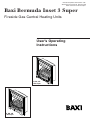
1
Please keep these instructions safe.
Should you move house, please hand
them over to the next occupier.
Baxi Bermuda Inset 3 Super
Fireside Gas Central Heating Units
User’s Operating
Instructions
TS, BS, KS
& SC Super
FS, BB, CB
& BC Super
Natural Gas
Codes of Practice, most recent version
should be used
Baxi Bermuda Inset 3 BS Super
G.C.No. 37 075 56
Baxi Bermuda Inset 3 TS Super
G.C.No. 37 075 57
Baxi Bermuda Inset 3 KS Super
G.C.No. 37 075 54
Baxi Bermuda Inset 3 FS Super
G.C.No. 37 075 55
Baxi Bermuda Inset 3 BB Super
G.C.No. 37 075 62
Baxi Bermuda Inset 3 CB Super
G.C.No. 37 075 63
Baxi Bermuda Inset 3 SC Super
G.C.No. 37 075 64
Baxi Bermuda Inset 3 BC Super
G.C.No. 37 075 65
For use with the following boiler:
Baxi Bermuda Inset 2 Boiler 50/4 E
G.C.No. 44 075 03
Baxi Bermuda Inset 3 Boiler 50/5
G.C.No. 44 075 07
In GB the following Codes of Practice apply:
Standard
Scope
BS 6891
Gas Installation.
BS 5440 Part 1
Flues.
BS 5440 Part 2
Ventilation.
BS 5871 Part 2
Installation of inset live fuel effect fires.
In IE the following Codes of Practice apply:
Standard
Scope
I.S. 813
Domestic Gas Installations.
IMPORTANT - The addition of anything that may
interfere with the normal operation of the
appliance without express written permission
from the manufacturer or his agent could
invalidate the appliance warranty. In GB this
could also infringe the GAS SAFETY (Installation
and Use) REGULATIONS.
IMPORTANT - Installation, Commissioning,
Service & Repair
This appliance must be installed in accordance with
the manufacturer’s instructions and the regulations
in force. Read the instructions fully before installing
or using the appliance.
Baxi is one of the leading manufacturers of domestic
heating products in the UK.
Our first priority is to give a high quality service to our
customers. Quality is built into every Baxi product products which fulfil the demands and needs of
customers, offering choice, efficiency and reliability.
To keep ahead of changing trends, we have made a
commitment to develop new ideas using the
latest technology - with the aim of continuing to
make the products that customers want to buy.
Everyone who works at Baxi has a commitment to
quality because we know that satisfied customers
mean continued success.
We hope you get a satisfactory service from Baxi. If
not, please let us know.
Baxi is a BS-EN ISO 9001
Accredited Company
2
In GB, this must be carried out by a competent
person as stated in the Gas Safety (Installation &
Use) Regulations.
Definition of competence: A person who works for a
CORGI registered company and holding current
certificates in the relevant ACS modules, or valid
ACoP equivalents, is deemed competent.
In IE, this must be carried out by a competent
person as stated in I.S. 813 “Domestic Gas
Installations”.
1.0 Warnings
Notice
1.1
Safe Installation
Discolouration of wall surfaces
Most heating appliances generate warm air convection currents and
transfer heat to any wall surface against which they are situated.
Some soft furnishings (such as blown vinyl wallpapers) may not be
suitable for use where they are subject to temperatures above normal
room levels and the manufacturer's advice should be sought before
using this type of wall covering adjacent to any heating appliance.
The likelihood of wall staining from convected air currents will be
increased in environments where high levels of tobacco smoke or other
contaminants exist.
Although the fire appears similar to a coal fire when operating care
should be taken to avoid throwing rubbish onto the coalbed.
Guarding
This appliance has a naked flame and a fireguard conforming
to B.S. 6539 or 6778 should be used, especially in instances
where young children, the elderly or infirm are likely to be
present.
Never Hang Flammable Items Over The Appliance
Shelf
1. If a shelf is to be fitted above the fire, then it must be at least
126mm (5in) above the fire and not more than 178mm (7in) in
depth.
2. Alternatively, a 229mm (9in) deep shelf may be fitted, but
must be at least 180mm (71/8in) above the fire.
The appliance is suitable only for installation in
GB and IE and should be installed in
accordance with the rules in force.
In GB, the installation must be carried out by a
CORGI Registered Installer. It must be carried
out in accordance with the relevant
requirements of the:
• Gas Safety (Installation & Use) Regulations.
• The appropriate Building Regulations either
The Building Regulations, The Building
Regulations (Scotland), Building Regulations
(Northern Ireland).
• The Water Fittings Regulations or Water
Byelaws in Scotland.
• The Current I.E.E. Wiring Regulations.
Where no specific instructions are given,
reference should be made to the relevant British
Standard Code of Practice.
In IE, the installation must be carried out by a
competent Person and installed in accordance
with the current edition of I.S. 813 ‘Domestic
Gas Installations’, the current Building
Regulations and reference should be made to
the current ETCI rules for electrical installation.
Read the instructions before installing or using
this appliance.
Any purpose provided ventilation should be checked
periodically to ensure that it is free from obstruction.
1.2
“Benchmark” Installation, Commissioning and Service Record
Log Book
Please ensure that your installer has completed the Installation and
Commissioning sections of the Log Book and hands the Log Book over.
The details of the Log Book will be required in the event of any warranty
work. Keep the Log Book in a safe place and ensure that the relevant
sections are completed at each subsequent regular service visit.
All CORGI registered installers carry a CORGI identification
card and have a registration number. Both should be recorded
in your boiler Log Book. You can check your installer is
registered by telephoning +44 (0)1256 372300 or writing to:1 Elmwood,
Chineham Business Park,
Crockford Lane,
Basingstoke. RG24 8WG
Important Information
This product uses fuel effect pieces containing
Refractory Ceramic Fibres (R.C.F.) which are manmade vitreous silicate fibres. Excessive exposure to
these materials may cause temporary irritation to
eyes, skin and respiratory tract. Care must be taken
when handling these articles to ensure the release of
dust or fibres is kept to a minimum. Refer to section
6.1 Cleaning the Fire.
1.3
In case of gas leaks
If a gas leak is found or suspected, turn off the
gas supply at the meter immediately and call your
gas supplier.
1.4
Servicing your Appliance
For reasons of safety and economy your appliance
should be serviced annually. Your Installer will be
able to advise you.
3
2.0 Introduction
2.1
Introduction
1. Your Baxi Bermuda Inset 3 Super is a central
heating boiler combined with a gas fire. The
firefront is of the Decorative Fuel Effect type and
incorporates an optional illumination effect for
use when the fire is off. The boiler will provide
heating for the rest of the house and also
domestic hot water if required. The boiler and fire
are independently controlled.
Boiler Thermostat
Knob
2. The boiler may be controlled by an external
programmer or clock control (see separate
instructions with the clock controller used).
Manual control is available with the boiler
thermostat control.
Green Power
ON Indicator
ON/OFF
Button
Green
High Setting
Indicator
Controls Access Door
Bermuda Inset 3
TS, BS, KS & SC Super
HIGH/LOW
Button
NOTE: The fire or illumination effect will not
function in the event of a power failure.
2.2
Controls and Identification (Fig. 1)
1. The controls for the fire are situated on the
upper left hand side of the fire surround.
Green
Illumination
ON Indicator
2. Remove the controls access door at the
bottom of the fire to gain access to the boiler
controls.
Fig. 1
Illumination
Button
3. Fire identification is situated on the inner right
hand side panel behind the controls access door.
Controls & Bezel
4. Boiler identification is on the boiler controls
behind the controls access door.
5. Before operating the unit ensure that the main
gas and electricity supplies are turned on.
2.3
Boiler Thermostat
Knob
Controls Access Door
4
Pilot/A.S.D.
1. Both the boiler and firefront are fitted with a
pilot light that also acts as an Atmospheric
Sensing Device. This means that in the event of
the flow of gases out of the flue being interrupted
the pilots will extinguish and shut the fire and
boiler down. If this occurs persistently your
Service Engineer should be contacted
immediately.
Bermuda Inset 3
FS, BB, CB & BC Super
3.0 Operating the Boiler
3.1
To light the boiler (Fig. 2 & 2a)
Ensure that all external controls, e.g. room
thermostat, timer etc., are calling for heat. To
operate the pilot turn the thermostat knob to the
desired position. The pilot light (50/4E) or indicator
light (50/5) will illuminate once the pilot is lit. The
burner will also light shortly after the pilot has been
established. The pilot is intermittent and only lights
when there is a call for heat.
If the boiler cannot be lit by the above method
consult your Service Engineer.
3.2
Controls Access Door
Boiler Controls
To adjust the boiler temperature
(Fig. 2 & 2a)
Turn the boiler thermostat knob clockwise to the
required setting. The optimum boiler thermostat
setting depends upon type of system, external
controls and your requirements. Your Installer will
be able to advise you on this matter.
3.3
Resetting the boiler
Gas Service Cock
Pilot Viewing Window
50/4 E
Boiler Controls
Green Pilot Light
Boiler Lockout Light
Boiler Thermostat
Knob
Fig. 2
1. Inset 2 Boiler 50/4 E Model (Fig. 2). If the
boiler lockout light is illuminated, it is necessary to
reset the appliance. To do this turn the boiler
thermostat control knob fully anticlockwise to the
OFF position and wait 10 seconds. Turn the
control knob clockwise to the required setting. the
boiler will commence the ignition sequence
providing the water temperature is sufficiently cool.
2. Inset 3 Boiler 50/5 Model (Fig. 2a). If the
indicator light is illuminated red/or flashing red, it is
necessary to reset the appliance. To do this turn
the boiler thermostat control knob fully anticlockwise to the OFF position and wait until the
light shows orange. Turn the control knob
clockwise to the required setting. The boiler will
commence the ignition sequence.
Gas Service Cock
3.4
Pilot Viewing Window
50/5
Boiler Controls
To switch off the boiler for short
periods (Fig. 2 & 2a)
1. Turn the boiler thermostat knob fully anticlockwise to the off position (O) until it clicks.
Indicator Light
Boiler Thermostat
Knob
3.5
To switch off the boiler for long
periods (Fig. 2 & 2a)
Fig. 2a
1. Turn the boiler thermostat knob fully anticlockwise to the off position (O) until it clicks.
2. It is recommended that if the system is left off
for long periods during cold weather the whole
system is drained to avoid frost damage.
3. Advice on draining the system can be obtained
from your Service Engineer.
5
4.0 Operating the Fire
The fire is controlled by three switches situated on
the upper left hand side of the fire surround. The
illumination effect operates independently to the
High & Low gas rates on the fire.
4.1
To operate the illumination effect
(Fig. 3)
1. To switch on the illumination, press the
button once. The green indicator will come on to
confirm this.
2. To switch off the illumination, press the
button once.
4.2
Green Power
ON Indicator
To light the fire (Fig. 3)
1. The fire has three settings:ON/OFF
Button
OFF
HIGH/LOW
Button
3. During the ignition sequence you will hear an
audible signal. This lasts for up to 20 seconds.
The fire will then automatically ignite on the low
setting.
Green
Illumination
ON Indicator
Fig. 3
Controls & Bezel
HIGH
2. The ON button has a safety feature built in. It
should be pressed and held for 3-4 seconds. (The
green power ON indicator comes on when the
ON/OFF button is pressed.)
Green
High Setting
Indicator
Illumination
Button
LOW
NOTE: If the ON/OFF button is pressed and
held for less than 3 seconds the fire will not
ignite. This is a built in safety feature.
4. If the fire fails to ignite or goes out at any time,
switch the fire off and repeat the procedure.
5. If you require the fire on the high setting, press
the High/Low button. The green high setting
indicator will come on to confirm this. This
operation can be undertaken during the ignition
sequence.
NOTE: It is recommended that the fire is
operated on HIGH initially.
6. To change the fire from high to low, press the
High/Low button once. The green high setting
indicator will go out to confirm this.
NOTE: When your Bermuda Inset 3 Super is first
used it is possible some smells may be emitted.
These smells will quickly clear with use.
4.3
To turn the fire off (Fig. 3)
1. Pressing the ON/OFF button once will turn the
fire off and the green power ON indicator will go
out to confirm this.
6
Side Cheek Location Stop
5.0 Arranging the Coals
5.1
Arranging the Coals
It is important that all the coals are used and
arranged as shown in order to achieve the
desired flame picture.
CAUTION: The coals are extremely fragile and
must be handled accordingly. Gloves should be
worn and any inhalation of the dust should be
avoided. Keep the coals away from children at
all times. Never use coals other than those
originally supplied or Genuine Baxi Spare Parts.
Never put additional coals on the fire. Please
read section 1.2 Important Information and
section 6.1 Cleaning the Fire.
Fig. 4
Combustion Box Base Front Lip
Rear Coal Side
Support Ledges
Fig. 5
Rear Coal Spacer Lugs
1. It may be necessary to remove some or all of the
coals to retouch or clean them at some time.
Cleaning must only be done using a very soft
brush. Any areas of the coal bed where the coating
has deteriorated may be retouched using the black
stain available direct from Baxi or from your local
Baxi Spares Stockist. Quote Part No 043224 when
ordering.
2. The following procedure assumes all the loose
coals, side cheeks, rear and front coals are to be
fitted. If not all the coals require replacement, refer
to the diagrams and determine at which point you
need to commence.
3. Place the right / left hand side cheeks against
the combustion box side walls (Fig. 4).
Burner
Bracket Lip
Fig. 6
Fig. 7
4. Locate the rear coal behind the combustion box
base front lip and angle it back against the side
cheek location stops (Figs. 4 & 5).
5. Locate the front coal onto the rear coal side
support ledges and behind the lip of the burner
bracket (Figs. 5 & 6).
6. Place 5 of the loose coals into the location
recesses of the front coal, (flat face downward).
The 3 centre coals should rest against the
corresponding rear coal spacer lugs. Orientation of
the coals should be as shown in order to achieve
the desired flame picture (Fig. 7).
7. Place the remaining 4 loose coals between the
front loose coals and the rear coal, (flat face
downwards). Orientation of the coals should be as
shown in order to achieve the desired flame picture
(Fig. 8).
Fig. 8
7
6.0 Spares and Cleaning
6.1
Cleaning the Fire
1. The fire may be cleaned with a damp cloth and
wiped with a soft duster. Do not use metal polish
on any parts of the appliance. (BC model only The fender assembly may be cleaned with a nonabrasive aluminium, brass or chrome liquid
cleaner.)
2. It is possible that some soot may be
deposited on the coals after use. This is
acceptable providing it is not allowed to
accumulate. Should any soot accumulation
become excessive the fuel effect pieces should be
removed from the fire for cleaning. it is
recommended that gloves are worn when handling
these items. Cleaning should be carried out in a
well-ventilated area or the open air by gently
brushing with a soft brush with the pieces/bed held
away from the face to avoid inhaling the dust. The
use of a normal domestic vacuum cleaner is not
recommended as it may blow dust back into the
air. Care must also be taken if retouching the fuel
effect pieces is required. Always wash hands
thoroughly after handling the fuel effect pieces.
Glass Retaining Assembly
6.2
Changing the Bulbs
Fig. 9
IMPORTANT: Only replace the bulb/s with a 12V
20W halogen capsule bulb available at most DIY
outlets, specialist electrical stores or from Baxi.
1. Remove the coals, placing them on a
newspaper or similar to prevent soiling
furnishings.
2. Lift out the glass retaining assembly (Fig. 9).
Halogen Bulbs
Fig. 10
3. Remove the bulb by pulling out from the
ceramic bulb holder to disengage the pins
(Fig. 10).
4. Fit the replacement bulb in reverse order.
NOTE: Halogen bulbs should not be handled with
bare fingers. Always use a cloth to grip the bulb.
5. Replace the glass retaining assembly and
reassemble the coal bed (see Arranging the Coals
- section 5.0).
6.3
Amber Glass Pieces
Cleaning or Changing the Glass
1. Remove the coals, placing them on a
newspaper or similar to prevent soiling
furnishings.
2. Lift out the glass retaining assembly (Fig. 9).
3. Carefully remove the three amber glass pieces
and clean (Fig. 11).
Fig. 11
8
4. Fit the new or cleaned glass and reassemble
the coals.
7.0 Guarantee
7.1
Guarantee
1. Your Baxi Bermuda Inset 3 Super is designed
and produced to meet all the relevant Standards.
2. Baxi provide a 3 year guarantee on the
Bermuda - other parts of the system are covered
by the Installer or other manufacturers. The
guarantee operates from the date installation is
completed for the customer who is the original
user.
3. To maximise the benefit from our guarantee we
urge you to return the reply-paid guarantee
registration.
4. This does not in any way prejudice your rights
at Common Law. Such rights between the
customer and the installer or supplier from whom
the unit was purchased remain intact.
Any component or part which becomes
defective during the guarantee period as a
result of faulty workmanship or material whilst
in normal use will be repaired or replaced free
of charge.
9
8.0 Notes
10
Baxi manufacture a comprehensive range of
products for the domestic heating market
Gas Central Heating Boilers
(Wall, Floor and Fireside models).
Independent Gas Fires.
Renewal Firefronts.
Gas Wall Heaters.
Solid Fuel Fires.
If you require information on any of these products,
please write to the Sales Department.
11
BAXI POTTERTON
Brownedge Road Bamber Bridge Preston Lancashire PR5 6SN
After Sales Service 08706 096 096 Technical Enquiries 08706 049 049
www.baxi.co.uk
Comp No 247853 - Iss 4 - 12/02