1
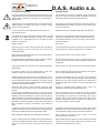
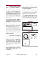
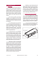
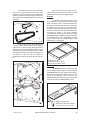
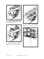
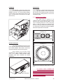
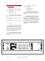
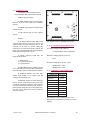
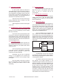
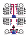
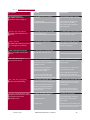
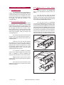
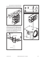
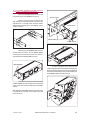
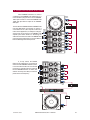
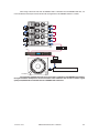
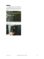
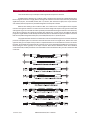
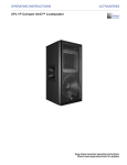
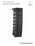
Variant series
Installation Line Array
®
VARIANT-25A
VARIANT-18A
Precauciones de seguridad
D.A.S. Audio s.a.
Safety Precautions
El signo de exclamación dentro de un triángulo indica la existencia de
componentes internos cuyo reemplazo puede afectar a la seguridad.
También indica instrucciones importantes de funcionamiento y
mantenimiento.
The exclamation point inside an equilateral triangle indicates the
existence of internal components whose substitution may affect
safety. Also indicates important operating instructions.
El signo del rayo con la punta de flecha alerta contra la presencia de
voltajes peligrosos no aislados. Para reducir el riesgo de choque
eléctrico, no retire la cubierta.
The lightning and arrowhead symbol warns about the presence of
uninsulated dangerous voltage. To reduce the risk of electric shock,
do not remove the cover.
Conserve estas instrucciones. Siga todas las advertencias. Lea
todas las instrucciones.
Keep these instructions. Heed all warnings. Follow all instructions.
Este símbolo en su equipo indica que el presente producto no puede
ser tratado como residuos domésticos normales, sino que deben
entregarse en el correspondiente punto de recogida de equipos
eléctricos y electrónicos.
This symbol on the product indicates that this product should not
be treated as household waste. Instead it shall be handed over to
the applicable collection point for the recycling of electrical and
electronic equipment.
Aparato de Clase I.
Class I device.
Para una protección continua contra el riesgo de fuego, reemplace el
fusible únicamente con otro del mismo tipo, que se indica en la
cubierta de la unidad.
For continued protection against risk of electric fire replace fuse only
with same type fuse, which is indicated on the cover of the unit.
Para reducir el riesgo de descarga eléctrica no exponga este equipo a
la lluvia, humedad o salpicaduras.
Do not expose this device to rain, moisture or splash.
No instale el sistema cerca del agua, piscinas y fuentes por ejemplo.
No deposite sobre él recipientes que contengan líquidos.
Do not use this apparatus near water- for example, swimming pool,
fountain. Do not place any object containing liquids as bottles on the
top of the unit.
Limpie el aparato sólo con un paño seco. No use limpiadores basados
en disolventes.
Clean only with a dry cloth. Do not use any solvent based cleaners.
No instale el aparato cerca de ninguna fuente de calor como
radiadores, estufas u otros aparatos que produzcan calor.
Do not install near any heat sources such as radiators, heat registers,
stoves, or other apparatus that produce heat.
El cable de alimentación suministrado con su unidad tiene conector
de tres terminales (tipo X). No corte o dañe el terminal de tierra. Si el
conector suministrado no puede conectarse en su enchufe, consulte
a un electricista para sustituir el enchufe obsoleto. Proteja el cable de
alimentación de ser pisado o pellizcado.
The power cord supplied with your unit has a 3-pin type plug (X
type). Do not cut off or damage the grounding pin. If the provided plug
does not fit in your outlet, consult an electrician for replacement of
the obsolete outlet. Protect the power cord from being walked on or
pinched.
Desconecte este aparato durante tormentas eléctricas, lluvia
torrencial, terremotos o cuando no se vaya a emplear durante largos
periodos.
No existen partes ajustables por el usuario en el interior de este
equipo. Cualquier operación de mantenimiento o reparación debe ser
realizada por personal cualificado. Es necesario el servicio técnico
cuando el aparato se haya dañado de alguna forma, tal como que el
cable de corriente o el enchufe se hayan dañado, haya caído líquido o
algún objeto en el interior del aparato, el aparato haya sido expuesto a
lluvia o humedad, no funcione correctamente o haya recibido un
golpe.
Unplug this apparatus during lightning storms, heavy rain,
earthquakes or when unused for long periods of time.
El colgado de la caja sólo debe realizarse utilizando los herrajes de
colgado y solamente por personal cualificado. No cuelgue la caja de
las asas. No reemplace pasadores de seguridad por tornillos.
The appliance should be flown only from the rigging points and by
qualified personnel. Do not suspend the box from the handles. Do not
use instead of quick release pins any other element as fasteners.
Nunca cuelgue más cajas de las recomendadas por el fabricante.
Never exceed the maximum number of units to be flown
recommended by the manufacturer.
Cuando se deban instalar dos unidades sobre trípode mediante el
suso del soporte AXC-V25 la altura máxima desde el suelo hasta el
mismo con los pies del trípode a su máxima extensión debe ser
140cm.
When installing two Variant 25A units on a tripod (using the AXC-V25
structure) the maximum safety height from floor to bottom of first
cabinet with tripod legs fully open: 140 cm
No user serviceable parts inside. Refer all servicing to qualified
service personnel. Servicing is required when the apparatus has
been damaged in any way, such as power-supply cord or plug is
damaged, liquid has been spilled or objects have fallen into the
apparatus, the apparatus has been exposed to rain or moisture, does
not operate normally, or has been dropped.
The components used in the system feature
advanced technologies; new T.A.F. (Total Air Flow)
cooling systems, neodymium magnets which allow
for important weight reductions, titanium diaphragms
for the high frequency sections, and low-mid
frequency cones manufactured using crossed fibers
and elastic suspension that provide exceptional
stability in the vertical plane.
The VARIANT 18A incorporates one 1250 W
(continuous) Class D amplifier along with the
necessary signal treatment to perform as a subwoofer unit. This amplifier features a high pass filtered
output at 138 Hz intended to provide signal for the
VARIANT 25A units.
Variant 25A
174
Both units are manufactured using
10/15mm Finnish Birch plywood. The VARIANT 25A
enclosure shape is trapezoidal with 7º angles. The
VARIANT 18A unit is rectangular. Both enclosures
feature a rugged, weather resistant, polyurethane
black paint and incorporate stainless steel and
aluminum captive rigging hardware which is
designed to provide fast, simple and safe rigging by
means of quick release safety pins. Splay angles can
be changed from 0º to 10º in 1º increments.
A three position eq switch located on the
amplifier panel allows for array effect correction (mid
and low frequencies sum in phase when several units
are assembled). This switch provides two additional
equalizations to adjust the high frequency range.
7º
The new D.A.S. Variant series was designed
for use in fixed installations, portable A/V, or
applications requiring high SPL and control of the
vertical coverage. The series comprises two models,
the VARIANT 25A which features two 5” speakers for
mid-low frequencies and one compression driver (2”
voice coil and 1” exit) coupled to a SERPIS-25 plane
wave generator for the high frequencies. The
VARIANT 25A model can be used alone as a frontfill or
under balcony unit for voice reproduction. The second
model is the VARIANT 18A bass system intended to
be used in combination with the VARIANT 25A for
applications requiring extension of the low frequency
range below 90 Hz.
The VARIANT 25A incorporate two Class AB
amplifiers featuring electronically balanced signal
inputs and outputs. The AC input and output link utilize
Neutrik PowerCon® connectors which allow up to 10
units to be daisy chained at 230 V.
574
231
1. SYSTEM DESCRIPTION
ALL DIMENSIONS IN MILIMETERS
Variant 18A
574
650
507
WARNING! DO NOT SUSPEND FROM THIS HANDLE
¡ATENCIÓN! NO CUELGUE LA CAJA DE ESTE ASA
For mid-low frequencies, the VARIANT 25A
incorporates two 5B 5” speakers with 1” voice coil
and ferrite magnet assemblies in a bass-reflex
configuration. High frequencies are handled by one M5N compression driver with 2” voice coil, neodymium
magnet and 1” exit coupled to one SERPIS-25 plane
wave adapter/ high frequency horn assembly
designed by D.A.S. Audio. In order to maintain
coherent horizontal dispersion one of the 5” speakers
features a low pass filter, avoiding destructive
interference between the 5” speakers in the mid
frequency range.
ALL DIMENSIONS IN MILIMETERS
The VARIANT 18A model includes one 18H
18” speaker with 4” voice coil and neodymium
magnet assembly in a bass-reflex configuration. It can
be flown above the mid-high units or as an
independent cluster.
Variant series
Manual del usuario/ User´s manual
24
2. RIGGING SYSTEM
2.1 WARNING
This manual contains needed information for
flying D.A.S. Audio line array systems, description of
the elements and safety precautions. To perform any
operations related to flying the system, read the
present document first, and act on the warnings and
advice given. The goal is to the allow the user to
become familiar with the mechanical elements
required to fly the acoustic system, as well as the
safety measures to be taken during set-up and
teardown.
Only experienced installers with adequate
knowledge of the equipment and local safety
regulations should fly speaker boxes. It is the user's
responsibility to ensure that the systems to be flown
(including flying accessories) comply with state and
local regulations.
The working load limits in this manual are
the results of tests by independent laboratories. It is
the user's responsibility to stay within safe limits. It is
the user's responsibility to follow and comply with
safety factors, resistance values, periodical
supervisions and warnings given in this manual.
Product improvement by means of research and
development is on going at D.A.S. Specifications are
subject to change without notice.
Absolutely no risks should be taken with
regards to public safety. When flying enclosures from
ceiling support structures, extreme care should be
taken to assure the load bearing capabilities of the
structures so that the installation is absolutely safe.
Do not fly enclosures from unsafe structures. Consult
a certified professional if needed. All flying
accessories that are not supplied by D.A.S. Audio are
the user's responsibility. Use at your own risk.
2.2 DESCRIPTION/ACCESORIES
D.A.S. Audio VARIANT 25A and VARIANT
18A units include two rigging structures on each side
of the enclosure. Manufactured from stainless steel
and aluminum, they are affixed with special M8 crop
resistant screws to the wood sides on both models. A
special connecting link is part of each rigging
structure and allows for both stacking or flying with
splay angles ranging from 0º to 10º in 1º increments.
In order to set up the splay angles the quick
release pins supplied with each unit must be used.
4 quick release pins are provided with VARIANT 25A
and 6 quick release pins with the VARIANT 18A.
Connecting Link
To this date, there is no international
standard regarding the flying of acoustic systems.
However, it is common practice to apply 5:1 safety
factors for enclosures and static elements. For slings
and elements exposed to material fatigue due to
friction and load variation the following ratios must be
met; 5:1 for steel cable slings, 4:1 for steel chain
slings and 7:1 polyester slings. Thus, an element with
a breaking load limit of 1000 kg may be statically
loaded with 200 kg (5:1 safety factor) and
dynamically loaded with 142 Kg (7:1 safety factor).
Variant 25A
When flying a system, the working load
must be lower than the resistance of each individual
flying point in the enclosure, as well as each box.
Hanging hardware should be regularly inspected and
suspect units replaced if in doubt. This is important to
avoid injury and absolutely no risks should be taken in
this respect. It is highly recommended that you
implement an inspection and maintenance program
on flying elements, including reports to be filled out by
the personnel that will carry out the inspections. Local
regulations may exist that, in case of accident, may
require you to present evidence of inspection reports
and corrective actions after defects were found.
Variant series
Manual del usuario/ User´s manual
25
To facilitate the insertion of the connecting
links in the corresponding slot of the top box, each
angle has an associated pin hole which is labeled and
located on each side of the box. Highly resistant 6mm
quick release pins with a ball safety lock are used set
the angles.
1º
6º
5º
7º
8º
10º
9º
4º
3º
2º
1º
4º
3º
2º
0º
0º
6º
5º
8º
7º
9º
10º
Most of the accessories needed to fly or
stack the units are integral to the enclosures. The only
additional items needed are the rigging bumpers.
A) AX-V25
The AX-V25 rigging grid (bumper) is made
from steel beams and is designed to handle great
loads. It features a center reinforcement bar that is
also used for the lifting slings. One chain can be used
to determine the tilt angle of the whole cluster,
depending on the hole used to attach the chain to the
center bar. The first box in the array will be attached to
the AX-25 by means of the above described
connecting links and quick release safety pins. Both
the VARIANT 25A and VARIANT 18A can be attached
to the AX-V25 bumper. Up to 20 VARIANT 25A units
can be flown from the AX-V25 bumper while
maintaining a 7:1 safety ratio.
In order to fly the units, the connecting link
must be rotated until the desired splay angle is
reached first (1). Then the quick release pin must be
introduced into the pin hole labeled with the desired
splay angle (2). The box will be flown from the rotating
point located in the top box as shown in the figure (3),
and finally the lower box will be secured by
introducing one more quick release pin in the top box
(4).
Weight: 5 kg (11 lb)
Dimensions: 5 x 57.4 x 39 cm
(H x W x D) 2 x 22.6 x 15.4 in
B) AXC-V25
The AXC-V25 is made from stainless steel
and has been specially designed to ceiling mount up
to 4 VARIANT 25A units. This ceiling mount accessory
also allows for hook clamps to be fixed to it, so up to 4
boxes can be attached to truss structures. The
VARIANT 25A units must be fixed to the ceiling mount
accessory by means of 4 M8x35 DIN912 screws.
3
4
1
2
Weight: 2.6 kg (5.7 lb)
Dimensions: 29 x 58.5 x 16.9 cm
(H x W x D) 11.4 x 23 x 6.6 in
Variant series
Manual del usuario/ User´s manual
26
Truss
M8x35 DIN912 screws
Garra
Hook Clamp
The AXC-V25 ceiling mount accessory
features several holes on the top plate which allow for
hook clamps to be fixed to them, so up to 4 units can
be flown from truss structures.
The AXC-V25 can also be used to
pole mount up to two units on top of one VARIANT
18A unit or on a tripod by making use of a special
adaptor.
AXC-V25
Tripod adaptor
One slot on each side of the AXC-V25
accessory allows for the setting of the tilt angle of the
whole cluster by means of the M8x35 screws
supplied.
Variant series
Manual del usuario/ User´s manual
27
C) AXW-V25
E) Chain hoists
The AXW-V25 is made from stainless steel
and has been specially designed to wall mount up to 3
VARIANT 25A units. Six special M8x35 DIN912
screws must be used to attach the accessory to the
wall. The whole cluster can be tilted as in the AXCV25 accessory.
All units in a column will be flown from the
AX-V25 rigging grid (bumper), which should be used
with one hoist. The maximum load that can be flown
using the AX-V25 is 285 kg (627 lb) so one 0.5 Ton
hoist will be enough.
2.3 SAFETY FACTORS
The safety factor is defined as the
coefficient between the breaking load limit and the
maximum safe working load limit (SWLL). In this
case, the breaking load limit of each of the flying
points is 1250 kg (2750 lb) as determined by
destructive testing in independent laboratories. With
a 7:1 safety factor, a total amount of 20 units VARIANT
25A can be suspended from the AX-V25.
2 x180 Kg (7:1)
D) Quick release pins
4 x180 Kg (7:1)
Each cabinet VARIANT 25A includes 4 steel
heavy duty quick release pins stored on the rear panel.
Each cabinet VARIANT 18A includes 6 steel heavy
duty quick release pins stored on the rear panel.
Both systems can be flown using
steel/aluminium rigging hardware located on both
sides of the cabinets. NEVER REPLACE QUICK
RELEASE PINS WITH SCREWS OR OTHER
ELEMENTS!!!
Each flying point withstands 180 Kg with a 7:1 safety
ratio.
Pasadores
Quick release pins
Variant series
The maximum number of VARIANT 25A
units that can be flown from the AX-V25 bumper is 20
units with a 7:1 safety ratio. The maximum number of
VARIANT 18A units that can be flown from the AXV25 bumper are 6 units. Never exceed the maximum
number of units recommended.
Manual del usuario/ User´s manual
28
3. SELF POWERED SYSTEM
3.1 VARIANT 25A
The VARIANT 25A is a two way class AB
self powered system.
Nominal amplifier power (Continuous) per
way: LF:125 W HF:75 W
Amplifier panel description:
A) LIMIT: Amplifier limiter indicator lights.
When lit, the level of the signal source should be
reduced.
B) SIGNAL: Signal presence indicator at the
amplifiers' inputs.
C) ON: Indicator light for each amplifier
channel.
D) FUSE.
F) INPUT: Balanced signal XLR. Pin
assignments as follows :
1=GND (ground)
2=(+) Non inverted input
3=(-) Inverted input
G) LOOP THRU: Used for paralleling several
units, which will share the same input. The output can
also be used to provide signal for an outboard power
amplifier.
H) ARRAY EQ: In order to compensate for the
summing of the mid and low frequencies, the onboard
signal processing of each VARIANT 25A unit provides
high frequency boost. The signal treatment has been
designed to provide optimum response for arrays of 6
or more cabinets, so when employing just two or
three units it may be appropriate to lower the high
frequency level. The ARRAY EQ switch can be used to
attenuate the equalization of the very high frequencies
in -3 dB steps.
E1) AC INPUT: Blue PowerCon® NAC 3 FCA
connector. Only when the connector is inserted and
rotated (clicked) into place will the AC turn on. The
connector can be used as a switch, rotating the
connector to or from the locked position will turn the
unit on or off, respectively. Mute the signal feeding the
INPUT before turning the unit on or off.
AC OUTPUT
AC INPUT
E1
®
Variant-25A
CAUTION
G
LOOP
THRU
F
INPUT
ATTENTION
risk of electric shock danger d’electrocution
do not open
ne pas ouvrir
WARNING: THIS PRODUCT MUST BE GROUNDED
REFER TO INSTRUCTIONS MANUAL FOR CONNECTION
NO USER SERVICEABLE PARTS INSIDE
ATENCIÓN: ESTE APARATO DEBE CONECTARSE A TIERRA
VEASE MANUAL DE INSTRUCCIONES PARA LA CONEXIÓN
NO EXISTEN PARTES AJUSTABLES POR EL USUARIO EN EL INTERIOR DE ESTE EQUIPO
ACHTUNG: DIESE PRODUKT MUSS GEERDET SEIN
ANSCHLUSSWEISE BITTE DER ANLEITUNG ENTNEHMEN
ES SIND KEINE VOM ANWENDER EINSTELLBAREN TEILE IM GERAET VORHANDEN
A
ATTENTION: CE PRODUIT DOIT ETRE RELIE A LA TERRE
VOIR MANUEL D'INSTRUCTIONS POUR LA CONNEXION
AUCUNE PIÉCE N’EST AJUSTABLE PAR L’UTILISATEUR Á L’INTERIEUR DE CET APPAREIL
B
C
Serial Number:
220V-240V
50Hz/60Hz
2A
D
T2A L 250V FUSE
E2
WARNING!
FOR CONTINUED PROTECTION AGAINST RISK
OF FIRE REPLACE ONLY WITH THE SAME TYPE MAX. 10 UNITS IN PARALLEL
E2) AC OUTPUT: White PowerCon® NAC 3
DFCB connector. This is used as an AC loop thru so
that up to 10 boxes (at 230V) can be powered from a
single AC line.
EUROPEAN
PRODUCT
Made in Spain
N1918
H
D.A.S. AUDIO S.A. (Valencia) SPAIN
LIMIT
HIGH
LIMIT
LOW
SIGNAL
ON
Array eq
2 UNITS
1 UNITS
Panel trasero del amplificador de los sistemas VARIANT 25A.
Variant series
Manual del usuario/ User´s manual
29
3.2 VARIANT 18A
Low frequency mono-amplified system.
Nominal amplifier power (Continuous) 1250 W.
Amplifier panel description:
A) LIMIT: Amplifier limiter indicator lights.
When lit, the level of the signal source should be
reduced.
I
A
B
C
B) SIGNAL: Signal presence indicator at the
amplifiers' inputs.
H
G
F
C) ON: Indicator light for each amplifier
D
channel.
E
D) FUSE.
E) AC INPUT: With PowerCon NAC 3 FCA
connector. Only when the connector is inserted and
rotated (clicked) into place will the AC turn on. The
connector can be used as a switch, rotating the
connector to or from the locked position will turn the
unit on or off, respectively. Mute the signal feeding the
INPUT before turning the unit on or off.
3.3 AC POWER REQUIREMENTS
F) INPUT: Balanced signal XLR. Pin
assignments as follows :
Maximum voltage (divide by 2 for115 V):
Rear amplifier panel on VARIANT 18A systems.
The required voltage for all models is:
115 V, 50 Hz/60 Hz - 230 V, 50 Hz/60 Hz
255 V
1=GND (ground)
2=(+) Non inverted input
3=(-) Inverted input
Shutdown voltage (divide by 2 for 115 V):
G) LOOP THRU: Used for paralleling several
units, which will share the same input. Could also be
used to provide signal for an outboard power amplifier.
H) SATELLITE OUTPUT: This sends highpassed signal (138Hz) to the system that will
reproduce mid-high frequencies.
I) SUB LEVEL: Used to control the subwoofer
level. To prevent accidental mis-setting, a flat-blade
screwdriver is needed to rotate the control, which is
recessed and detented. Depending on the sensitivity,
placement and configuration of your mid-high system,
you may need to adjust this control for balanced
frequency response.
VARIANT 25A: 160 V
VARIANT 18A: 160 V
3.4 CURRENT CONSUMPTION
VARIANT 25A
Maximum Power
1/3 Power
1/8 Power
Idle
Pink Noise
0.7 A
0.45 A
0.3 A
0.15 A
VARIANT 18A
Maximum power
1/3 Power
1/8 Power
Idle
Pink noise
3.5 A
1.8 A
0.9 A
0.1 A
Data obtained at 230 V, multiply per 2 for 115 V.
Maximum power: Measured in conditions of severe
clipping.
Variant series
Manual del usuario/ User´s manual
30
3.5 SWITCH ON-OFF
3.8 EQUALIZATION
A sound system should be switched on
sequentially. Switch on the self-powered unit last in
your sound system. Switch on the sound sources
such as CD players or turntables, then the mixer, then
the processors, and finally the self-powered unit. If
you have several units, it is recommended that you
switch them on sequentially one at a time.
Follow the inverse order when switching off,
turning self-powered units off before any other
element in the sound system.
Mute all signal sources before switching the
unit on or off.
3.6 OVERLOAD (LIMIT) INDICATORS
It is recommended that the red LIMIT LED
indicators are not lit continuously; at most it should
blink only occasionally.
If you wish to have a visual indication at the
mix position of whether the LIMIT LEDs are lighting,
during equipment set-up, closely observe what mixer
VUmeter level corresponds to the level that lights the
enclosure's LIMIT LEDs. That level that should not be
exceeded during the event.
3.7 OVERHEATING
The Variant Series amplifiers generate very
little residual heat and therefore do not need a fan for
cooling. In normal use, the amplifier panel will be
warm to the touch.
The units do not need extreme EQ. Avoid
high levels of gain on the equalizers. Gain values
above +6 dB on a console's EQ are not
recommended.
3.9 LOW MAINS VOLTAGE
If mains voltage falls below the shutdown
voltage for the unit, it will stop playing. When
acceptable levels are regained, the unit will switch
back on automatically.
3.10 CONNECTIONS
The VARIANT 25A unit can be used alone for
speech applications where low SPL is suitable. To use
it in this mode simply plug the mixer into the input
signal connector. To use it in combination with the
VARIANT 18A unit, plug the mixer into VARIANT 18A
(INPUT) and connect the SATELLITE OUTPUT to the
signal input on the VARIANT 25A unit.
When the VARIANT 25A and VARIANT 18A
units cannot be on the same cluster it is
recommended to drive each model separately from a
signal processor using a 138 Hz High Pass Filter for the
VARIANT 25A, adding the necessary time delay if
requeired and feeding the VARIANT 18A with the full
range signal.
138Hz
Mezclador/Mixer
If the unit stops playing (or just the mid-high
or the bass sections), the amplifier's overheating
protection may be activated to protect the
components from thermal damage.
Overheating may be due to insufficient
cooling, or to very aggressive use in extremely hot
conditions. Do not use the unit in proximity to high
power lights.
Once the amplifier cools down, it switches
back on automatically. If the unit should shut down
again, try reducing the volume a notch to avoid
overheating.
Variant series
Retardo/
Delay
Procesador/
processor
VARIANT 25A
VARIANT 18A
The LOOP THRU connector is an output XLR
in parallel with the input connector and is useful for
daisy chaining the input signal to a number of boxes,
connecting them in parallel.
The number of units that can be linked this
way depends on the output impedance of the
equipment driving the enclosure, such as the mixer or
processor. Typically, to avoid signal degradation, the
maximum number that can be daisy chained is given
by the formula Zc>10Zs, where Zc is the load
impedance and Zs is the output impedance of the
equipment driving the enclosure (mixer, console, etc).
For instance, a mixing console with 100 ohm output
impedance allows daisy chaining 20 boxes, when the
input impedance of the cabinets is 20 kohms.
Manual del usuario/ User´s manual
31
SIGNAL
INPUT
SIGNAL
INPUT
SATELLITE
OUTPUT
SATELLITE
OUTPUT
138 Hz
POWER
INPUT
138 Hz
LINE
POWER
INPUT
LINE
Connection employing the filtered Satellite Output .
POWER
INPUT
POWER
INPUT
SIGNAL
INPUT
SIGNAL
INPUT
Connection using an external processor
to adjust the delay between systems.
138 Hz
Delay
125
Hz
Delay
125
Hz
LINE
SIGNAL
INPUT
Variant series
SIGNAL
INPUT
Manual del usuario/ User´s manual
32
3.11 TROUBLESHOOTING
PROBLEM
CAUSE
SOLUTION
No sound from the unit.
The SIGNAL presence LED
indicator(s) do(es) not light up.
1- The signal source is sending
no signal.
1- Check that the mixer or sound
source is sending signal to the UNIT.
2- Defective cable.
2- Check that the cable from the
sound source to the UNIT is
connected correctly. Replace the
cable if defective.
Full power cannot be obtained.
The LIMIT LED indicator(s) never
light(s) up.
1- The signal source does not have
a hot enough output.
1- If using a mixer, use the balanced
output if available. Use a professional
mixer with a hotter output.
Sound is distorted.
The LIMIT LED indicator(s) is/are not
on, or only light up occasionally.
1- The mixer or signal source
is distorting.
1- Turn mixer channel gains down.
Check that none of your signal
sources are distorting.
Sound is distorted and very loud.
One or more LIMIT LED indicators
light up.
1- The system is overloaded and
has reached maximum power.
1- Turn down the mixer's output.
Hum or buzz when a mixer
is connected to the unit.
1- The console probably has
un-balanced outputs. You may
be using an incorrect un-balanced
to balanced cable.
1- Read the appendix of this manual
to make a correct un-balanced to
balanced cable.
2- The mixer and the powered
speaker are not plugged into
the same mains outlet.
2- Connect the mixer and the unit
to the same mains outlet.
3- The audio signal cable is too
long or too close to an AC cable.
Hum or buzz when using lighting
controls in the same building.
1- The audio signal cable is too
long or too close to the lighting cable.
2- On a sound system with threephase AC, the lighting equipment
and the UNIT are connected to
the same phase.
The power on LED indicator(s) do(es)
not light up when the power connector
is rotated and locked at the
ON (LOCK) position.
1 Bad or loose AC connection to
the UNIT or the mains outlet.
2 Faulty AC cable.
3 Blown Fuse.
Variant series
Manual del usuario/ User´s manual
3- Use a cable that is as short as
possible and/or move the audio
signal cable away from mains cables.
1- Move the audio signal cable away
from lighting cables. Try to find out
at what point the noise is leaking
into the system.
2- Connect the sound system to
a different phase than the lights.
You may need the help of an electrician
1- Check you connections.
2- Check the cables, connectors
and AC power with a suitable
mains tester.
3- Replace fuse on fuse holder with
one of the same type. If it blows again,
take the unit to a service centre.
33
4. SYSTEM INSTALLATION
4.1INTRODUCTION
The VARIANT 25A unit can be installed in a
number of ways. Typically several VARIANT 25A units
would be assembled to form a line array cluster, but it
can also be used alone, as a frontfill or as an underbalcony unit. A wide range of accessories and uses
are available, and have been described in the
paragraphs below.
4.2 PLANNING/INSPECTION
Before installing the VARIANT 25A system
it is advisable to run a simulation using the EASE
FOCUS software utilizing the venue dimensions. This
way we can determine the needs that should be met
by the rigging structures such as hoists, cranes,
beams, rigging points, etc. Besides providing weight
information, the program also provides users with
splay angle information, safety pin positions and
coverage predictions.
4.3 INSTALLING A LINE ARRAY
SYSTEM
Whenever a cluster of only VARIANT 25A
units is to be assembled the procedure will be as
follows:
First step will be to attach the AX-V25
bumper to the hoist. The chain sling needs to be
attached to the structure using the shackle provided
with the grid. The shackle will be inserted into the hole
recommended by the EASE FOCUS software.
The next step will be to mechanically
connect the first VARIANT 25A to the AX-V25. In order
to do so rotate the connecting links (1) and then insert
the safety pins through the labeled holes to select the
splay angle between the VARIANT 25A and the grid
(2). Now both connecting links must be inserted into
the receptacles on the AX-V25 (3). Once this has been
done two more safety pins have to be inserted to
secure the boxes (4). It is highly advisable to check
that all of the safety pins have been correctly inserted.
It is extremely important to assure that each
and every one of the aforementioned structures is
capable of supporting a superior load than that of the
complete system.
Inspection is the next step after planning
and acquiring all the necessary parts needed to
elevate the systems. All parts, including the hardware
attached to the enclosure, the safety pins, etc. should
be thoroughly inspected before each use. Units
exhibiting deformations, cracks or any other defect
should be replaced with new units.
3
4
1
2
It is important to establish an inspection
routine for the complete rigging system before each
event or installation as well as establishing the
maximum load specifications of the hoists to be used.
Rigging should be carried out by experts
familiar with the way the system functions and their
characteristics.
On occasions it may be convenient to have
additional tie down points to impede the array from
twisting or swinging.
6
5
Variant series
Manual del usuario/ User´s manual
34
The procedure to mechanically connect the
second unit is similar. First rotate the connecting links
(5) in order to select the correct angle by means of the
safety pins (6). In this example the selected angle is
2º. Once this has been done then the enclosure must
be hung from the first box (7) and assured by means of
one more safety pin (8).
3
4
2
1
7
Cluster of six VARIANT 25A.
8
The above described procedure applies to
the rest of the units.
The basic procedure to hang the units is as
follows: rotate the connecting links (1) until the
desired angle is reached. Then introduce the safety
pins through the holes labeled with the desired angle
which should have been provided by the prediction
software EASE FOCUS (2). Now introduce the
connecting links into the receptacles of the box above
and hang the unit from the rotating point (3). Finally
introduce the safety pin that secures the unit (4). This
procedure will be repeated as many times as
enclosures are to be assembled.
Variant series
Manual del usuario/ User´s manual
35
4.4 ASSEMBLING A SYSTEM WITH
FLOWN SUBWOOFERS
The VARIANT 18A units feature integral
rigging hardware allowing them to be flown
independently or above VARIANT 25A enclosures.
-5º
0º
5º
0º
VARIANT 18
AX-V25
1
VARIANT 25
The first step will be to mechanically
connect the first VARIANT 18A to the AX-V25 grid. 6
safety pins are included in the rear side of the box in
order to do so. First rotate the rear side connecting
links by 180º, and then the front side connecting links
until the VARIANT 18A AX-V25 labeled position has
been reached. After that, insert the pin through the
hole labelled VARIANT 18A AX-V25(2).
The next step will be to hang one more
VARIANT 18A unit below the first one. To do so first
both connecting links will be rotated (4), then a safety
pin will be inserted into the hole labeled VARIANT 18A
(5) on the front side connecting link, and finally both
connecting links will be introduced into the rigging
hardware of the box above and secured by means of
two more safety pins (6).
6
1
2
5º
0º
6
4
5
VARIANT 18
AX-V25
0º
VARIANT 25
4
-5º
To secure the enclosure to the grid (3) two
more safety pins are needed on each side. Check that
the position of the connecting links are as shown in
the image below.
If VARIANT 25A units are to be hung from
the VARIANT 18A subwoofers, first the connecting
links have to be rotated (7), then the safety pin must
be inserted into the hole that provides the desired
angle (8), and finally the connecting links have to be
introduced into the rigging hardware of the box above
and be secured by means of a safety pin on each side
(9).
3
3
9
7
8
Variant series
Manual del usuario/ User´s manual
36
4.5 STACKING UNITS ON THE SUBS
The VARIANT 18A units feature integral
rigging hardware which can also be used for stacking
VARIANT 25A units on top of them. The maximum
recommended number of VARIANT 25A units in this
mode is 6. The splay angles available between both
enclosures are 0º, 5º and -5º.
In order to attach the VARIANT 25A unit to
the subwoofer unit, introduce the connecting (5) links
on the VARIANT 18A into the receptacles on the
VARIANT 25A. Then two safety pins (6) must be
introduced (one per side) to secure one enclosure to
the other.
The first step will be to mechanically
connect the first VARIANT 25A unit to the VARIANT
18A enclosure. Four safety pins, which are included in
the box, will be necessary to do so. First rotate the
connecting links (1) on the VARIANT 18A until the
desired angle is achieved and introduce the safety pin
through the hole labeled with the desired splay angle
(2). The three available angles are 0º, 5º and -5º. Look
at the label on the VARIANT 18A box.
5º
6
VARIANT 25
0º
0º
VARIANT 18
AX-V25
-5º
5
In the picture above the safety pin has been
introduced into the 0º labeled hole, while in the picture
below the safety pin has been introduced into the +5º
labeled hole.
1
2
Before attaching the first VARIANT 25A to
the subwoofer unit, the connecting links must be
rotated (3) until the desired splay angle with the next
unit on top is reached. Once the desired angle has
been reached the safety pins will be introduced (4)
into the corresponding hole.
The rest of the boxes will be set up using the
above explained procedure for connecting rods and
safety pins. (See page 12)
4
3
Variant series
Manual del usuario/ User´s manual
37
4.6 SYSTEM INSTALLATION USING
THE CEILING SUPPORT AXC-V25
The VARIANT 25A units can be set up as a
long array of more than four enclosures (as explained
above) or as a small array of 2, 3 or 4 units. In the latter
case the highly resistant AX-V25 grid accessory is not
necessary. Instead the AXC-V25 ceiling mount
accessory can be used to hang a cluster of up to four
units.
Grower (lock) washer
Metal washer
First attach the ceiling mount accessory to
the ceiling or a beam. Before doing so be sure that the
load bearing capability of these elements is enough.
The AX-V25 will be attached to the ceiling by means of
six nº 10 rawlplugs and six 7 x 40 mm screws.
M8x35 DIN 912
Rubber washer
Three different washers must be used along
the M8x35 DIN912 screws and placed in the following
order- grower (lock) washer, metal washer and rubber
washer.
AXC-V25
In order to hang the rest of the boxes the
captive rigging hardware and safety pins will be used,
and the procedures described on the 4.3 paragraph of
this manual will be followed. The picture below shows
three VARIANT 25A units hanging from the ceiling.
Before connecting the first box to the ceiling
mount accessory the two M8x30 DIN965 screws
must be removed from the VARIANT 25A and
replaced by two M8x35 DIN912.
M8X30 DIN965
Variant series
Manual del usuario/ User´s manual
38
20º
When a pair of hook clamps are attached to
the ceiling mount accessory, it can be fixed to a truss
structure such as the one shown in the picture below:
The AXC-V25 accessory can also be used as
a support for up to two VARIANT 25A units on a pole
mount accessory, on top of one VARIANT 18A unit. To
do so the AXC-V25 accessory is to be used upsidedown and a special pole mount adaptor must be fixed
to it by means of two M8x35 DIN912 screws, nuts
and washers. A 10º splay angle is recommended in
order to achieve a 20º vertical coverage.
AXC-V25
M8x35 DIN912
Adaptor
Pole Mount
Variant series
Manual del usuario/ User´s manual
39
4.7 SYSTEM INSTALLATION USING
THE WALL SUPPORT AXW-V25
Up to three VARIANT 25A units can be wall
mounted by means of the AXW-V25 accessory.
Grower washer
First the accessory must be fixed to the
wall, making sure in advance that the work load of the
wall allows for it. The wall mount accessory will be
attached to the wall using six nº 10 rawlplugs and six
7 x 40 mm screws.
Metal washer
M8x35 DIN 912
Rubber washer
Then hang the first VARIANT 25A unit from
the wall mount accessory. The two M8x30 DIN965
screws have to be removed from each side of the box
and replaced by two M8x35 DIN912 screws.
M8X30 DIN965
In order to hang the rest of the boxes the
captive rigging hardware and safety pins will be used,
and the procedures described on the 4.3 paragraph of
this manual will be followed. The picture below shows
three VARIANT 25A units fixed to the wall.
Three different washers must be used along
the M8x35 DIN912 screws and placed in the following
order- grower (lock) washer, metal washer and rubber
washer.
Warning!! If three VARIANT 25A units have to be hung
it is advisable to fix the box in the middle to the wall
mount accessory.
Variant series
Manual del usuario/ User´s manual
40
5. USING THE SYSTEM WITH SUBS
When VARIANT 25A units are used in
combination with VARIANT 18A subwoofers it is
recommended to plug the mixer into the VARIANT
18A's input and then to connect the VARIANT 18A
138Hz high pass filtered output to the VARIANT
25A input.
The ratio between VARIANT 25A and VARIANT 18A
units that DAS Audio recommends to achieve a
correct balance is 4:1 (As it depends on the kind of
music and the application, it is subject to changes).
A level knob can be found on the VARIANT 18A
amplifier panel which allows for decreasing the
subwoofer level when less than four VARIANT 25A
units are to be used, allowing to correct the balance
between Mid-High and Low frequencies.
SIGNAL
INPUT
SATELLITE
OUTPUT
138 Hz
POWER
INPUT
LINE
If, for any reason, the Satellite
Output on the subwoofer is not going to be
used to feed the VARIANT 25A units, then it
is recommended to make use of an external
processor to high pass filter the signal fed
into the VARIANT 25A unit at 138 Hz, and
add the necessary time delay to match the
phase at the cut off frequency.
POWER
INPUT
SIGNAL
INPUT
138 Hz
LINE
Delay
125
Hz
SIGNAL
INPUT
Variant series
Manual del usuario/ User´s manual
41
When using a subwoofer other than the VARIANT 18A in combination with the VARIANT 25A units, it is
recommended that external processor be used to filter the signal fed into the VARIANT 25A units at 138 Hz.
POWER
INPUT
SIGNAL
INPUT
138 Hz
LINE
Delay
125
Hz
138 Hz
AMPLIFIER
SUB MODEL X
If an externally amplified subwoofer unit is to be used in combination with VARIANT 25A satellites,
the signal treatment will depend on the characteristics of the subwoofer used. In order to achieve a good
quality sound, DAS Audio recommends the use of VARIANT 18A subwoofers.
Variant series
Manual del usuario/ User´s manual
42
To remove the amplifier the enclosure has to
bepositioned face downwards, on the aluminum front
grill. Then remove the four M5x10 DIN965 screws
that fix the amplifier to the sides of the box.
6. MAINTENANCE
VARIANT 25A
In order to access the 5B 5” speakers, the
four M4x8 DIN965 screws that fix the aluminium grill
to the box, should be removed. To replace the
speakers, remove the four M4x20 DIN7985 screws.
If the compression driver’s diaphragm
needs replacement, or access to the compression
driver is needed for any reason, the amplifier must
have be removed previously. To replace the
compression driver, unplug the connection wires and
rotate the driver. If only the diaphragm is to be
replaced, then remove the three screws that fix the
membrane to body of the driver and change it.
Variant series
Manual del usuario/ User´s manual
43
VARIANT 18A
In order to access the 18” 18H speaker, the
six M4x8 DIN965 screws that fix the grille to the
aluminum sides have to be removed first. Then
remove the 8 M5x35 DIN7985 screws to replace the
speaker.
To access to the amplifier twelve M4x20
DIN965 screws that fix it to the rear side of the box
must be removed.
Variant series
Manual del usuario/ User´s manual
44
7. SPECIFICATIONS
MODEL VARIANT 25A
LF Amplifier Power
HF Amplifier Power
Input Type
Input Impedance
Sensitivity
Frequency Range (-10 dB)
Horizontal Coverage (-6dB)
Vertical Coverage
Rated Maximum Peak SPL at 1 m
Transducers/Replacement Parts
Enclosure Geometry
Enclosure Material
Color/Finish
Rigging System Splay Angles
250 Wpeak - 125 Wcontinuous
150 Wpeak - 75 Wcontinuous
Balanced Differential Line
Line: 20 kohms
Line: 1.54 V (+6 dBu)
75 Hz-17 kHz
90º Nominal
Splay Dependent
120 dB
LF: 2 x 5B/5B
HF: 1 x M-5N/GM M-5
Trapezoidal 7º
Birch Plywood
Black or White Paint
0º to 10º in 1º increments
Safety Factor Maximum 20 cabinets @ 7:1
Connectors INPUT: Female XLR
LOOP THRU: Male XLR
AC INPUT: PowerCon NAC 3 FCA
AC OUTPUT: Powercon NAC 3 DFCB
AC Power Requirements 115 V @ 50 Hz/60 Hz
230 V @ 50 Hz/60 Hz
Dimensions (H x W x D) 17.4 x 57.4 x 23.1 cm
6.9 x 22.6 x 9 in
Weight 12.5 kg (27.5 lb)
Accessories AX-V25 (Black)/AX-V25W (White)
AXW-V25 (Black)/AXW-V25W (White)
AXC-V25 (Black)/AXC-V25W (White)
VARIANT 18A
2500 Wpeak - 1250 Wcontinuous
Balanced Differential Line
Line: 20 kohms
Line: 1.54 V (+6 dBu)
33 Hz-156 Hz
N/A
N/A
134 dB
LF: 1 x 18H/GM 18G
Rectangular
Birch Plywood
Black or White Paint
0º to 5º in 1º increments
(V-25A under V-18A)
Maximum 6 cabinets @ 7:1
INPUT: Female XLR
LOOP THRU: Male XLR
SATELLITE OUT: Male XLR
AC INPUT: PowerCon NAC 3 FCA
115 V @ 50 Hz/60 Hz
230 V @ 50 Hz/60 Hz
50.7 x 57.4 x 65 cm
19.9 x 22.6 x 25.6 in
49 kg (108 lb)
AX-V25 (Black)/AX-V25W (White)
Product improvement through research and development is an ongoing process at D.A.S. All specifications are subject to
change without notice.
Variant series
Manual del usuario/ User´s manual
45
APPENDIX. LINE CONNECTION: UN-BALANCED AND BALANCED.
There are two basic ways to transport an audio signal with microphone or line level:
Un-balanced line: Utilizing a two-conductor cable, it transports the signal as the voltage between them.
Electro-magnetic interference can get added to the signal as undesired noise. Connectors that carry un-balanced
signals have two pins, such as RCA ( Phono) and ¼” (6.35 mm, often referred to as jack) mono. 3-pin connector
such as XLR ( Cannon) may also carry un-balanced signals if one of the pins is unused.
Balanced line: Utilizing a three-conductor cable, one of them acts as a shield against electro-magnetic
noise and is the ground conductor. The other two have the same voltage with respect to the ground conductor but
with opposite signs. The noise that cannot be rejected by the shield affects both signal conductors in the same way.
At the device’s input the two signals get summed with opposite sign, so that noise is cancelled out while the
programme signal doubles in level. Most professional audio devices use balanced inputs and outputs. Connectors
that can carry balanced signal have three pins, such as XLR ( Cannon) and ¼” (6.35 mm) stereo.
The graphs that follow show the recommended connection with different types of connectors to balanced
processor or amplifier inputs. The connectors on the left-hand side come from a signal source, and the ones on the
right hand side go to the inputs of the processor or amplifier. Note that on the un-balanced connectors on the lefthand side, two terminals are joined inside the connector. If hum occurs with balanced to balanced connections, try
disconnecting the sleeve (ground) on the input connector. Note that the illustrations show what should be
connected to what, but that pin locations on an actual XLR connector are different. Also, pin 2 hot is assumed on XLR
connectors.
Variant series
Manual del usuario/ User´s manual
46
US/variant-00
D.A.S. AUDIO, S.A. C/. Islas Baleares, 24 - 46988 Fuente del Jarro - Valencia, SPAIN
Tel. Intl. +34 96 134 0860 - Fax. Intl. +34 96 134 0607
D.A.S. AUDIO of AMERICA, Inc. Sunset Palmetto Park - 6816 NW 77th Court - Miami, FL 33166 U.S.A.
TOLL FREE: 1-888DAS4USA Tel. 305 436 0521
D.A.S. AUDIO DEUTSCHLAND GmbH Frankfurter Straße 17 - 64546 Mörfelden-Walldorf
Fon. +49 06105-967610 Fax 06105-96761
www.dasaudio.com