1
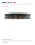
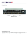
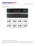
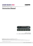
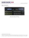
M U LT IM EDIA AUDIO A ND V IS UA L
8x8 Composite Video Stereo/Digital Audio
Matrix Routing Switcher
INSTRUCTION MANUAL
MODEL : SB-5548
8x8 Composite Video Stereo/Digital Audio Matrix Routing Switcher
Composite Video Stereo/Digital Audio Matrix Routing Switcher Series
Thank you for purchasing the SB-5548 Composite Video Stereo/Digital Audio Matrix Routing Switcher. You will
find this unit easy to install and highly reliable but it is essential that you read this manual thoroughly before
attempting to use this switcher.
SAFETY INFORMATION
1.
To ensure the best results from this product, please read this manual and all other documentation before operating your equipment.
Retain all documentation for future reference.
2.
Follow all instructions printed on unit chassis for proper operation.
3.
To reduce the risk of fire, do not spill water or other liquids into or on the unit, or operate the unit while standing in liquid.
4.
Make sure power outlets conform to the power requirements listed on the back of the unit. Keep unit protected from rain, water and
excessive moisture.
5.
Do not attempt to clean the unit with chemical solvents or aerosol cleaners, as this may damage the unit. Dust with a clean dry cloth.
6.
Do not use the unit if the electrical power cord is frayed or broken. The power supply cords should be routed so that they are not
likely to be walked on or pinched by items placed upon or against them, paying particular attention to cords and plugs, convenience
receptacles, and the point where they exit from the appliance.
7.
Do not force switched or external connections in any way. They should all connect easily, without needing to be forced.
8.
Always operate the unit with the AC ground wire connected to the electrical system ground. Precautions should be taken so that the
means of grounding of a piece of equipment is not defeated.
9.
AC voltage must be correct and the same as that printed on the rear of the unit. Damage caused by connection to improper AC
voltage is not covered by any warranty.
10. Turn power off and disconnect unit from AC current before making connections.
11. Never hold a power switch in the “ON” position.
12. This unit should be installed in a cool dry place, away from sources of excessive heat, vibration, dust, moisture and cold. Do not use
the unit near stoves, heat registers, radiators, or other heat producing devices.
13. Do not block fan intake or exhaust ports. Do not operate equipment on a surface or in an environment which may impede the normal
flow of air around the unit, such as a bed, rug, carpet, or completely enclosed rack. If the unit is used in an extremely dusty or smoky
environment, the unit should be periodically “blown free” of foreign dust and matter.
14. To reduce the risk of electric shock, do not remove the cover. There are no user serviceable parts inside. Refer all servicing to
qualified service personnel. There are no user serviceable parts inside.
15. When moving the unit, disconnect input ports first, then remove the power cable; finally, disconnect the interconnecting cables to
other devices.
16. Do not drive the inputs with a signal level greater than that required to drive equipment to full output.
17. The equipment power cord should be unplugged from the outlet when left unused for a long period of time.
18. Save the carton and packing material even if the equipment has arrived in good condition. Should you ever need to ship the unit,
use only the original factory packing.
19. Service Information Equipment should be serviced by qualifier service personnel when:
A. The power supply cord or the plug has been damaged.
B. Objects have fallen, or liquid has been spilled into the equipment.
C. The equipment has been exposed to rain
D. The equipment does not appear to operate normally, or exhibits a marked change in performance
E. The equipment has been dropped, or the enclosure damaged.
THIS SAFETY INFORMATION IS OF A GENERAL NATURE AND MAY BE SUPERSEDED BY INSTRUCTIONS CONTAINED WITHIN THIS MANUAL
INTRODUCTION
INTRODUCTION ..................................................3
FEATURES & SPECIFICATIONS ...........................4
CAUTION
RISK OF ELECTRIC SHOCK
DO NOT OPEN
CAUTION: TO REDUCE THE RISK OF ELECTRIC SHOCK,
FRONT PANEL .....................................................5
REAR PANEL ........................................................6
REMOTE CONTROL ............................................7
IR EXTENDER ......................................................8
RS-232 SERIAL INTERFACE ...............................9
RS-232 PROTOCOL COMMANDS ........................9
LIMITED WARRANTY ........................................10
DO NOT REMOVE COVER (OR BACK),
NO USER SERVICEABLE PARTS INSIDE,
REFER SERVICING TO QUALIFIED SERVICE PERSONAL.
WARNING!
TO REDUCE THE RISK OF FIRE OR ELECTRIC SHOCK
DO NOT EXPOSE THIS EQUIPMENT TO RAIN OR MOISTURE.
This symbol is intended to alert the user to the presence of non-insulated
“dangerous voltage” within the products enclosure that may be of sufficient
magnitude to constitute a risk of electric shock to persons.
This symbol is intended to alert the user to the presence of important operational
and maintenance (serving) instructions in the literature accompanying the
appliance.
To prevent electric shock do not use this (polarized) plug with an extension cord,
receptacle or other outlet unless the blades can be fully inserted to prevent blade
exposure. To prevent electric shock, match wide blade of plug to wide slot, fully
insert.
INTRODUCTION
Congratulations on your purchase of one of the most innovative 8x8 Composite Video/Audio matrix switching product on the market Today.
The SB-5548 is a true Matrix Routing Switcher for Composite Video/Audio (Stereo Audio) signals. It is an 8 individual A/V (Composite
Video) inputs with 8 individual A/V outputs. Because it is a matrix router, any input may be routed to any output; or the same input may be
routed to all outputs or any combination. It completely eliminates the need to constantly move around audio and video input and output
cables. The SB-5548 is useful for Matrix signals from AV source devices (such as: VCRs, Camcorders, Video Game Consoles, Video
CDs, DVDs, Satellite Receivers, CAT5 Set Top Boxes, etc.) to AV destination devices (such as: HDTV, LCD TVs, Plasma TV Sets, Video
Projectors, etc.). Selection of inputs is made via the Front Panel push buttons or an Infrared Remote Control unit or RS-232 control by
computer.
Package Includes:
(1) SB-5548 8x8 Matrix Switcher
(2) IR Remote Control
(3) RS-232 Cable
(4) Rack Mounts
(5) Control Software (All Windows Operating Systems)
(6) Users Guide
(7) AC/DC Adapter: 12VDC, 500mA
AC/DC Adaptor Types : CE/UL/SAA/BS
Safety Notice!
To prevent damage to your television equipment use only the supplied
AC Adaptor and make the power connections to your television
3
FEATURES & SPECIFICATIONS
FEATURES
•
•
•
•
•
•
•
•
•
Supports 8x inputs to 8x outputs A/V (Composite Video-Audio) Matrix Switcher
Input/Output signals via Composite Video & Stereo Audio (AR/AL)
Higher Video Bandwidth 450MB each path signals.
Supported selection buttons direct channel on front panel
Video support Composite Video switch the NTSC or PAL TV system
Compatible with all Composite Video devices, Plasma TV display and HDTV
Supported RS-232 serial interface protocol commands list
Control PC RS-232 Drive compatible with win-95/98/2000/xp
Various User Interface controls:
• Attached Window based control software for Desktop or NB control by RS-232 port
• Manual controlled by Front Panel button
• IR remote control
• Support desktop with Ear mount and 19 inch 1U Rack mountable type panel
• Power supply DC12Volt, Universal Type Switch 100~230VAC, 50/60Hz
SPECIFICATIONS
• Type of Switcher: 8 in To 8 out, A/V (Composite Video-Audio) Matrix Switcher
• Input Ports:
• Video: 8x sets of 3-RCA
• Audio: 8x sets of (2) RCA (Left and Right OR Digital-Coax)
• Output Ports:
• Video: 8x sets of 3-RCA
• Audio: 8x sets of (2) RCA (Left and Right OR Digital-Coax)
• Video Bandwidth: 450MHz (-3db), 200mVp-p
• Video Supported: Higher resolution formats
• Audio Supported: Stereo Audio (AR/AL)
• Low All Hostile Crosstalk: -83 db@5MHz
• Controls: IR remote, Select buttons on the front panel & RS-232
• PC RS-232 Control: RS-232 interface serial via DRV on a PC
• Gain Control: 60MHz 0.1 db gain flatness
• Chassis Material: Metal
• Dimensions (WxDxH): 17.32 x 7.87 x 1.73 in (440mm x 200mm x 44mm)
• Shipping Weight: 3.25 Kgs / 5.41 lbs
• Safety Approvals: CE, FCC, RoHS(2002/ 95 / EC)
• Power Supply: DC12V / 2A (consumption 1250mA Max), Use Universal Switch Type 50/60Hz,100~230 VAC
As product improvements are continuous, specifications are subject to change without notice.
4
FRONT PANEL
FRONT PANEL
1. POWER ON SWITCH
The power switch turns the unit on and off. The LED will illuminate red to indicate that the switcher is ON and is receiving power.
The Switcher will remember that last state during a power cycle. When power is removed and resorted, the last configuration will be evoked.
2. INPUT STATUS DISPLAY
Input sources 1 to 8 LED illuminates blue to indicate that a video source is present on that input.
3. OUTPUT STATUS DISPLAY
Each Output (destination ) Channel shows which input (source) is assigned.
4. DESTINATION SELECT BUTTONS
Separate outputs 1 thru 8 select buttons are provided for each destination assignment. Routing can be Source to Destination or one
source to multiple destinations.
Example: Press Destination 1, 3, 5 then press Source 2 will route Input 2 to Output 1, 3, 5 respectfully.
5. SOURCE SELECT BUTTONS
Separate inputs 1 thru 8 select buttons are provided each source selection.
6. IR SENSOR
The IR sensor receives IR commands from the supplied remote controller or third party IR emitter.
7. 19 INCH EAR MOUNT PAIR
Converts desk-top to 19 inch rack mount bracket (part # 1U-440L) INCLUDED. Image shows rack mount bracket attached.
5
FRONT PANEL cont’d
FRONT PANEL
8. FUNCTION KEY - ALL
Disables (mute) video on all destinations OR Selects the same source to all destinations.
Option 1
- Press ALL followed by OFF button. The display will show” a • indicating all destinations have no video selected.
Option 2
- Press ALL followed by Source 1 thru 8. The display will show the Source selected and assign that source to all destinations.
9. FUNCTION KEY - OFF
Disables (mute) video to selected channels. Either Sources or destinations.
- Press OFF button followed by any Source or Destination channel.
- Press 1 thru 8 input source or 1 thru 8 output destination. The display will show ” 0 “ for the selected channel indicating no video selected.
10. FUNCTION KEY - RECALL
The system will show previously stored presets, up to a total of 16. Presets are stored in local memory using Source keys 1 thru 8 or
Destination keys 1 thru 8 as the memory preset location.
- Press RECALL button.
- Press 1 thru 8 on either Source or Destination row.
- Press ENTER The pre-set configuration will execute.
Operation completes.
Note: Operation will abort if no keys are dressed within 5 seconds.
11. FUNCTION KEY - ENTER or DEMO
Press ENTER to confirm entries.
12. FUNCTION KEY - MEMORY
The system will show store presets, up to a total of 16. Presets are stored in local memory using Source keys 1 thru 8 or Destination keys
1 thru 8 as the memory preset location.
- Configure desired matrices ..
- Press MEMORY button.
- Press 1 thru 8 on either Source or Destination row.
- Press ENTER to ready memory location.
- Or press MEMORY again to cancel operation.
Operation completes.
Note: Operation will abort if no keys are dressed within 5 seconds.
13. FUNCTION KEY - LOCK
- Press and hold LOCK button for two seconds lockout the front panel.
- Press and hold LOCK button for two seconds to enable front panel.
6
BACK PANEL
BACK PANEL
Power Jack:
DC Jack - Inner OD Ø 2.1 mm (+)
Outside OD Ø 5.5mm (GND)
Power input -12VDC, 1A-2A
1. DC POWER INLET:
The switcher is fitted with a DC power plug input connector.
Please ensure that the plug used is of an approved type and is
of sufficient current carrying capacity with the correct voltage and
connector polarity. 12Volt DC power supply 1A-2A Max.
2. IR EXTENDER CONTROL:
Support one of IR Extender (IR input) Extend distance maximum
300 Meters or 1000 feet.
IR Extender Jack: Female Jack - inner OD Ø 3.5mm
3. RS-232 CONNECTION:
RS-232 control port to allow for interfacing to a PC, such as a
computer or touch panel control, to the switcher via this DB-9pin
Female connector for serial RS-232 control.
Remote port: DB-9pin Female connector
4. INPUTS-1~8 COMPOSITE/AUDIO (AR/AL):
Connect a signal source of Composite Video and stereo Audio
(AR/AL) devise to 8x8 matrix switcher.
Input 1~8 port source signals :
- Composite Video/Stereo Audio, 3x RCA Connectors
Composite Video Audio Via 3x RCAs
Note: With 3x RCA female connectors.
5. OUTPUTS-1~8 COMPOSITE/AUDIO (AR/AL):
Connect a signal of Composite Video and Stereo Audio (AR/
AL) direct to Female RCA connector. This connector supports
Composite Video and Stereo Audio display device.
Composite Video Audio Via 3x RCAs
Note: With 3x RCA female connectors.
Output 1~8 display port signals :
- Composite Video and Stereo Audio, 3x RCA Connectors
CONNECTING THE HARDWARE
Please study the panel drawings below and become familiar with the signal input-output, Power requirements plus any controls present.
Before using the switcher, please take the time to make certain that the device you wish to connect to its inputs is functioning properly in
all respects. Verify that the video and audio signals are present and are being displayed properly on a suitable device. If all is well connect
the appropriate cables between the output of the device you wish to distribute to output(s) of the switcher to the carious devices you wish
to feed a signal to. Lastly, connect the AC to DC adaptor, connect the DC connector to the switcher first and then plug the adaptor into a
functional AC outlet.
7
REMOTE CONTROL
Before making any connections to the SB-5548. Observe the following:
Ensure the mains voltage supply matches the label on the supplied plug- Pack (+/- 10%).
Ensure that the power switch is OFF.
Ensure that all system grounds (earth) are connected to a common point.
Avoid powering equipment within a system from multiple power sources that may be separated by large distances.
Connect all audio video sources and destination equipment.
Power up all source and destination audio-visual sources.
For each destination output select the appropriate input source by using The front panel input 1-8 select buttons. The supplied IR remote control.
Or through the RS-232 serial communications port.
Upon power up the switcher will return to its last used setting before Powered down.
REMOTE CONTROL
IR REMOTE CONTROL KEY :
IR REMOTE : SW-5548C
1. & 2. SWITCH POWER ON or OFF:
Controller with a power ON and OFF
3. DESTINATION : 1 thru 8 OUTPUT SELECTION:
Press the destination button to select the output display channel.
4. SOURCE : 1 thru 8 INPUT SOURCE SELECTION:
Press input 1~8 sources with selection button
5. FUNCTION KEY:
ALL - function selection button
OFF - function selection button
RECALL - function selection button
DEMO or ENTER - function selection button
MEMORY - function selection button
LOCK - function selection button
8
REMOTE PROTOCOL COMMANDS
IR REMOTE CUSTOM AND DATA CODES (NEC Standard)
HOW TO SETUP IR CODES :
CUSTOM CODE : 00 FF
POWER ON : 00FF 00FF
POWER OFF : 00FF 01FE
ALL : 00FF B04F
OFF : 00FF B14E
PRESS TV DESTINATION - # then PRESS AV SOURCE - #
DESTINATION #1 : IR auto suggestion
DESTINATION #5 : IR auto suggestion
SOURCE #1 : 10EF 01FE
SOURCE #2 : 10EF 02FD
SOURCE #3 : 10EF 03FC
SOURCE #4 : 10EF 04FB
SOURCE #5 : 10EF 05FA
SOURCE #6 : 10EF 06F9
SOURCE #7 : 10EF 07F8
SOURCE #8 : 10EF 08F7
SOURCE #1 : 50AF 01FE
SOURCE #2 : 50AF 02FD
SOURCE #3 : 50AF 03FC
SOURCE #4 : 50AF 04FB
SOURCE #5 : 50AF 05FA
SOURCE #6 : 50AF 06F9
SOURCE #7 : 50AF 07F8
SOURCE #8 : 50AF 08F7
DESTINATION #2 : IR auto suggestion
DESTINATION #6 : IR auto suggestion
SOURCE #1 : 20DF 01FE
SOURCE #2 : 20DF 02FD
SOURCE #3 : 20DF 03FC
SOURCE #4 : 20DF 04FB
SOURCE #5 : 20DF 05FA
SOURCE #6 : 20DF 06F9
SOURCE #7 : 20DF 07F8
SOURCE #8 : 20DF 08F7
SOURCE #1 : 609F 01FE
SOURCE #2 : 609F 02FD
SOURCE #3 : 609F 03FC
SOURCE #4 : 609F 04FB
SOURCE #5 : 609F 05FA
SOURCE #6 : 609F 06F9
SOURCE #7 : 609F 07F8
SOURCE #8 : 609F 08F7
DESTINATION #3 : IR auto suggestion
DESTINATION #7 : IR auto suggestion
SOURCE #1 : 30CF 01FE
SOURCE #2 : 30CF 02FD
SOURCE #3 : 30CF 03FC
SOURCE #4 : 30CF 04FB
SOURCE #5 : 30CF 05FA
SOURCE #6 : 30CF 06F9
SOURCE #7 : 30CF 07F8
SOURCE #8 : 30CF 08F7
SOURCE #1 : 708F 01FE
SOURCE #2 : 708F 02FD
SOURCE #3 : 708F 03FC
SOURCE #4 : 708F 04FB
SOURCE #5 : 708F 05FA
SOURCE #6 : 708F 06F9
SOURCE #7 : 708F 07F8
SOURCE #8 : 708F 08F7
DESTINATION #4 : IR auto suggestion
DESTINATION #8 : IR auto suggestion
SOURCE #1 : 40BF 01FE
SOURCE #2 : 40BF 02FD
SOURCE #3 : 40BF 03FC
SOURCE #4 : 40BF 04FB
SOURCE #5 : 40BF 05FA
SOURCE #6 : 40BF 06F9
SOURCE #7 : 40BF 07F8
SOURCE #8 : 40BF 08F7
SOURCE #1 : 807F 01FE
SOURCE #2 : 807F 02FD
SOURCE #3 : 807F 03FC
SOURCE #4 : 807F 04FB
SOURCE #5 : 807F 05FA
SOURCE #6 : 807F 06F9
SOURCE #7 : 807F 07F8
SOURCE #8 : 807F 08F7
9
RS-232 SERIAL INTERFACE
RS-232
RS-232 SERIAL CONNECT
The Shinybow switcher can be controlled via the RS-232 serial control port
to allow for interfacing to a PC, or similar third party control system.
Pin
RS-232
1
------
Not used
The serial communication parameters are 9600 baud, 8 bit, No Parity and
1 stop bit - this is often referred to as 9600 8N1. When the unit recognizes
a complete command it will perform the requested action - there is no
delimiter character required.
2
TX
Transmitter
The unit does not send out a message when a value is changed from the
front panel or by IR control. If the unit needs to be controlled via the front
panel in addition to the RS-232 control, you should regularly poll the unit
status to ensure the control system accurately reflects the current settings.
Definition
3
RX
Receiver
4
------
Not used
5
GND
Ground
6
------
Not used
7
------
Not used
8
------
Not used
9
------
Not used
COMMANDS
POWER OFF MODE
To Switch Inputs to Outputs
SBI0XO0Y - Where X is Output Number (1-8) and Y is Input
Number (1-8)
SBSYSMOF - Put system into Standby (Soft Power Off)
SBSYSMON - Bring unit out of Standby (Soft Power On)
Unit will respond with
SBALOFAK - Unit is in Standby
SBALONAK - Unit is no longer in Standby
Unit will respond with
SBUD0XOY - Where X is Output Number (1-8) and Y is Input
Number (1-8)
Example: Put Unit in Standby (Soft Power)
SBSYSMOF - Send
SBALOFAK - Rcvd
Example: Send Input 8 to Output 7
SBI08O07 - Send
SBUD08O7 - Rcvd
FRONT PANEL LOCK
MORE STUFF FOR SB-5548
Note: Hard resetting the unit will unlock the Front Panel controls.
Note: Turning the unit System Power Off over RS-232 will
extinguish the LED channel display leaving only the Power switch
LED on. The Video and Audio outputs will also mute. While the
unit is turned off by RS-232 it will continue to accept and act upon
switching commands. For example, if the unit is in the off mode
(via RS-232) and you send a command to switch an input to an
output, that route will complete and the video and audio will now
appear on that channel only. The front panel LED channel display
for that particular output will also show the input selected (for that
single output channel only). The remaining LED’s will remain off
and video and audio outputs muted. The unit will still return status
and change messages in response to commands sent while in
Power Off state. A hard reset command (SBALLRST) will return
the unit to normal operation and also unlock the front panel.
SBSYSMLK - When front panel is locked, changes can only be
made by RS-232
SBSYSMUK - Front Panel Unlock
Unit will respond with
SBSYSLOK - Front Panel has been Locked
SBSYSULK - Front Panel has been Unlocked
Example: Lock Front Panel Buttons
SBSYSMLK -Send
SBSYSLOK -Rcvd
UNIT RESET
SBALLRST - Reset every output to Input 1
Unit will respond with
SBRSTACK - Unit has reset each Output to Input 1
Example: Reset all outputs to Input 1
SBALLRST - Send
SBRSTACK - Rcvd
10
IR EXTENDER
REAR PANEL IR EXTENDER PORT
*** When you plug the External IR extender into the switcher, the front panel IR receiver remains active. ***
IR EXTENDER PACKAGE :
HOW TO SETUP THE IR EXTENDER COMPONENTS
11
TYPICAL APPLICATION
8x A/V (Composite Video) sources to 8x A/V Output Matrix Switcher
SB-5548
INSTALLING
CONTROL PORTS:
1. IR REMOTE - IR Remote Controller
2. RS-232 Interface - RS-232 interface system
INPUTS 1 - 8 PORT HD SOURCE SIGNALS:
COMPOSITE VIDEO - Composite Video, connector with RCA
AUDIO - Stereo Audio (AR/AL), connector with RCA
OUTPUT 1 - 8 PORT HDTV DISPLAY SIGNALS:
COMPOSITE VIDEO - Composite Video, connector with RCA
AUDIO - Stereo Audio (AR/AL), connector with RCA
SB-5548 SUPPORT COMPONENT EIGHT INPUTS MATRIX TO EIGHT SWITCH OUTPUTS
SUPPORT CONTROL IR & RS-232 INTERFACE SYSTEM PORTS.
11
LIMITED WARRANTY
SHINYBOW WARRANTY
SHINYBOW Technology warrants this product against defects in materials and workman ship for a period of 3 years from the date of purchase. Please be sure to send
in your warranty registration card promptly, as the warranty will not be active without registration.
Should this product, in SHINYBOW Technology’s opinion, after inspection, prove defective within this warranty period, SHINYBOW Technology, at its option, will repair
or replace this product without charge, to whatever extent it shall deem necessary to restore said product to proper operation condition. This does not extend the
warranty period.
This warranty does not apply if the fault has been caused by misuse, improper handling care, electrical or mechanical abuse, and abnormal operating conditions or
non-SHINYBOW Technology authorized modification to the product.
If repairs are necessary under the warranty policy, the original purchaser must return the product to local distributor, freight prepaid. After repairs are complete, the
product will be returned.
REGULATORY COMPLIANCE
The product complies with the relevant standards for CE, FCC and RoHS approval.
The power Adaptor/Supply has been tested for compliance with UL.CSA and CE standards.
TROUBLESHOOTING
If you experience a <no signal> with this switcher or distributor outputs, first make certain that there is a signal being fed to its inputs from the connected device is
acceptable.
Disconnect the cables from the switcher or distributor inputs and connect them directly to an appropriate monitoring device. If you do not see or hear a signal the
problem may well be he signal source itself. Also check that the AC outlet you have used to power the switcher or distributor is actually providing power as a wall switch
often controls an AC outlet.
Verify that there is power to the device. If the unit is receiving power, the power on indicator light in the power switch should be glowing.
The second most common problem with the switcher or distributor revolves around the cables, Inspect the cables for loose connectors or cable damage such as
crushed cable or cables with cuts or nicks. Replace any cable exhibiting these problems.
We recommend using the highest quality cables so that you can achieve the best results. Poor quality cables provide will poor quality signals.
DISCLAIMER OF WARRANTIES AND LIABILITY
Neither Shinybow nor its suppliers or licensors makes any warranty whatsoever, including without limitation, that any defects will be corrected; including the accuracy,
completeness, reliability, availability, suitability, quality, non-infringement, operation or result obtained from the use of any content, product or service provided accessible
from or distributed through Shinybow.
ALL CONTENT, PRODUCTS AND SERVICES INCLUDED IN OR ACCESSIBLE ARE PROVIDED “AS IS” AND WITHOUT WARRANTIES OR REPRESENTATIONS
OF ANY KIND (EXPRESS, IMPLIED AND STATUTORY, INCLUDING BUT NOT LIMITED TO THE WARRANTIES OF TITLE AND NON-INFRINGEMENT AND THE
IMPLIED WARRANTIES OF MERCHANTABILITY AND FITNESS FOR A PARTICULAR PURPOSE), ALL OF WHICH SHINYBOW DISCLAIMS TO THE FULLEST
EXTENT PERMITTED BY LAW. YOUR USE OF THE CONTENT, PRODUCTS AND SERVICES IS AT YOUR SOLE RISK.
To the extent permitted under applicable law, no responsibility is assumed for any injury and/or damage to persons, animals or property as a matter of products liability,
negligence or otherwise, or from any use or operation of any ideas, instructions, methods, products or procedures contained.
TO THE EXTENT PERMITTED UNDER APPLICABLE LAW, IN NO EVENT SHALL SHINYBOW OR ITS SUPPLIERS OR LICENSORS BE LIABLE FOR ANY DAMAGES
(INCLUDING, WITHOUT LIMITATION, CONSEQUENTIAL, SPECIAL, INCIDENTAL, INDIRECT, OR SIMILAR DAMAGES, PERSONAL INJURY (INCLUDING DEATH),
LOSS OF PROFITS, CORRUPTION OR LOSS OF DATA, BUSINESS INTERRUPTION OR ANY OTHER COMMERCIAL DAMAGES OR LOSSES) ARISING OUT
OF OR IN CONNECTION WITH THE USE OR PERFORMANCE OF CONTENT, PRODUCTS OR SERVICES, OR SHALL THE LIABILITY OF SHINYBOW OR
ITS SUPPLIERS AND LICENSORS EXCEED A SUM EQUAL TO THE FEES PAID BY YOU HEREUNDER, EVEN IF ADVISED OF THE POSSIBILITY OF SUCH
DAMAGES.
Shinybow does not claim ownership, endorse or take responsibility for any third-party products, information, guidelines, materials or services that may be offered,
advertised, provided or incorporated in the content, products or services.
INDEMNIFICATION
You hereby agree to indemnify and hold Shinybow, its directors, officers, shareholders, predecessors, successors in interest, employees, agents, suppliers and
licensors harmless from and against any and all third-party claims of liability, losses, damages and costs, including, without limitation, reasonable attorneys’ fees, arising
out of or in connection with your use of or inability to use the content, products or services.
10
M U LT IM EDIA AUDIO A ND V IS UA L
1399 Wildfire Lane | Frisco, TX 75034
1-877-SHINY-USA
1-877-744-6987
1-972-377-2508
[email protected]
www.shinybowusa.com