1
MFC-CB™
MFC Control Box
Operation and Maintenance Manual
©2001~2007 DH Instruments, a Fluke Company
MFC-CB™ Operation and Maintenance Manual
© 2001~2007 DH Instruments, a Fluke Company All rights reserved.
Information in this document is subject to change without notice. No part of this document may be reproduced or
transmitted in any form or by any means, electronic or mechanical, for any purpose, without the express written
permission of DH Instruments, a Fluke Company 4765 East Beautiful Lane Phoenix AZ 85044-5318 USA.
DH Instruments strives to ensure the accuracy of its published materials; however, no warranty, expressed or
implied, is provided. DH Instruments disclaims any responsibility or liability for any direct or indirect damages
resulting from the use of the information in this manual or products described in it. Mention of any product does not
constitute an endorsement by DH Instruments of that product. This manual was originally composed in English and
subsequently translated into other languages. The fidelity of the translation cannot be guaranteed. In case of conflict
between the English version and other language versions, the English version predominates.
DH Instruments, DH, DHI, MFC-CB, molbox, MFC-CB, molbloc and CalTool are trademarks, registered and
otherwise, of DH Instruments, a Fluke Company.
Document No. 550123b-01
040330
Printed in the USA.
©2001~2007 DH Instruments, a Fluke Company
TABLE OF CONTENTS
TABLE OF CONTENTS
TABLE OF CONTENTS ................................................................................ I
TABLES ................................................................................................... IV
FIGURES ................................................................................................. IV
ABOUT THIS MANUAL ............................................................................... V
1. INTRODUCTION .................................................................................... 1
1.1
1.2
PRODUCT OVERVIEW .............................................................................................................................1
SPECIFICATIONS .....................................................................................................................................1
1.2.1
1.2.2
1.2.3
1.2.4
1.2.5
1.2.6
GENERAL SPECIFICATIONS ...........................................................................................................................1
ANALOG OUTPUT SPECIFICATIONS .............................................................................................................2
ANALOG INPUT SPECIFICATIONS .................................................................................................................2
VALVE TEST POINT SPECIFICATIONS ..........................................................................................................2
FRONT AND REAR PANELS............................................................................................................................3
1.2.5.1 FRONT PANEL ..................................................................................................................................3
1.2.5.2 REAR PANEL ....................................................................................................................................4
INTERNAL VIEW ...............................................................................................................................................5
1.2.6.1 DISPLAY ............................................................................................................................................5
1.2.6.2 POWER SUPPLY ..............................................................................................................................5
1.2.6.3 POWER ENTRY MODULE ................................................................................................................6
1.2.6.4 MICRO BOARD .................................................................................................................................6
1.2.6.5 MAIN BOARD ....................................................................................................................................6
2. INSTALLATION ..................................................................................... 7
2.1
UNPACKING AND INSPECTION ..............................................................................................................7
2.1.1
2.1.2
2.2
2.3
SITE REQUIREMENTS..............................................................................................................................8
INITIAL SETUP..........................................................................................................................................8
2.3.1
2.3.2
2.4
REMOVING FROM PACKAGING .....................................................................................................................7
INSPECTING CONTENTS .................................................................................................................................7
PREPARING FOR OPERATION .......................................................................................................................8
MFC-CB TO MFC OR MFM CONNECTION ......................................................................................................8
POWER UP AND VERIFICATION.............................................................................................................8
2.4.1
2.4.2
POWER UP ........................................................................................................................................................8
CHECK/SET SECURITY LEVEL .......................................................................................................................9
3. OPERATION ....................................................................................... 11
3.1
GENERAL MANUAL OPERATION .........................................................................................................11
3.1.1
3.1.2
3.2
MAIN RUN SCREEN........................................................................................................................................11
GENERAL OPERATING PRINCIPLES ...........................................................................................................12
3.1.2.1 KEYPAD LAYOUT AND PROTOCOL .............................................................................................12
3.1.2.2 SOUNDS..........................................................................................................................................13
3.1.2.3 SOFT [ON/OFF] KEY.......................................................................................................................14
3.1.2.4 ACTIVE DEVICE CHANNEL INDICATION......................................................................................14
3.1.2.5 DIRECT FUNCTION KEYS SUMMARY ..........................................................................................14
DIRECT FUNCTION KEYS......................................................................................................................16
3.2.1
3.2.2
3.2.3
3.2.4
[K].....................................................................................................................................................................16
[UNIT] ...............................................................................................................................................................17
[POWER]..........................................................................................................................................................18
[DISPLAY]........................................................................................................................................................19
3.2.4.1 <1DEV1&2> .....................................................................................................................................20
3.2.4.2 <2SUM> ...........................................................................................................................................21
3.2.4.3 <3DIF>(DIFFERENCE)....................................................................................................................21
3.2.4.4 <4RATIO> ........................................................................................................................................22
3.2.4.5 <5UNIT>...........................................................................................................................................23
Page I
©2001~2007 DH Instruments, a Fluke Company
MFC-CB™ Operation and Maintenance Manual
3.2.5
3.2.6
3.2.7
3.2.8
3.2.9
3.3
[SETUP] ...................................................................................................................................................29
3.3.1
3.3.2
3.3.3
3.3.4
3.3.5
3.4
3.2.4.6 <6CLEAN> .......................................................................................................................................24
[DEV1/2] ...........................................................................................................................................................25
[MFC]................................................................................................................................................................25
[DRIVERS] (OPTIONAL) .................................................................................................................................27
[SET MFC]........................................................................................................................................................27
[←] AND [→] (JOG MFC SET POINT) ............................................................................................................28
<1MFC> (EDIT MFC PROFILES) ....................................................................................................................30
<2JOG> ............................................................................................................................................................31
<3RES> (RESOLUTION) .................................................................................................................................32
<4FLOWU> (FLOW UNITS).............................................................................................................................32
<5ADJ> (ADJUSTMENT) ................................................................................................................................33
[SPECIAL] ...............................................................................................................................................35
3.4.1
3.4.2
3.4.3
3.4.4
3.4.5
3.4.6
3.4.7
<1RESET>........................................................................................................................................................36
3.4.1.1 <1SETS>..........................................................................................................................................36
3.4.1.2 <2UNITS> ........................................................................................................................................37
3.4.1.3 <3MFC> ...........................................................................................................................................37
3.4.1.4 <4CAL> ............................................................................................................................................37
3.4.1.5 <5ALL>.............................................................................................................................................38
<2LEVEL> ........................................................................................................................................................38
3.4.2.1 SECURITY LEVELS ........................................................................................................................39
<3PREFS>........................................................................................................................................................42
3.4.3.1 <1SCRSVR> ....................................................................................................................................42
3.4.3.2 <2SOUND> ......................................................................................................................................43
3.4.3.3 <3TIME> ..........................................................................................................................................43
3.4.3.4 <4ID> ...............................................................................................................................................44
<4CAL> ............................................................................................................................................................45
<5REMOTE> ....................................................................................................................................................45
3.4.5.1 <1COM1> AND <2COM2> ..............................................................................................................46
3.4.5.2 <3IEEE-488>....................................................................................................................................46
3.4.5.3 <4RS232 SELF-TEST>....................................................................................................................46
<6XBOX> .........................................................................................................................................................47
<7LOG>............................................................................................................................................................49
4. REMOTE OPERATION ......................................................................... 51
4.1
4.2
OVERVIEW ..............................................................................................................................................51
INTERFACING.........................................................................................................................................51
4.2.1
4.2.2
4.3
COMMANDS............................................................................................................................................54
4.3.1
4.3.2
4.3.3
4.3.4
4.4
RS232 INTERFACE .........................................................................................................................................52
4.2.1.1 COM1...............................................................................................................................................52
4.2.1.2 COM2...............................................................................................................................................53
IEEE-488 (GPIB) ..............................................................................................................................................53
COMMAND SYNTAX .......................................................................................................................................54
COMMAND SUMMARY ...................................................................................................................................54
ERROR MESSAGES .......................................................................................................................................55
COMMAND DESCRIPTIONS...........................................................................................................................56
4.3.4.1 IEEE STD. 488.2 COMMON AND STATUS COMMANDS..............................................................56
4.3.4.2 MFC-CB COMMANDS.....................................................................................................................59
STATUS SYSTEM ...................................................................................................................................74
4.4.1
STATUS REPORTING SYSTEM .....................................................................................................................74
4.4.1.1 STATUS BYTE REGISTER .............................................................................................................74
4.4.1.2 STANDARD EVENT REGISTER .....................................................................................................76
5. MAINTENANCE, ADJUSTMENTS AND CALIBRATION ............................ 77
5.1
5.2
OVERVIEW ..............................................................................................................................................77
VERIFICATION AND CALIBRATION OF ELECTRICAL SIGNALS .......................................................78
5.2.1
5.2.2
5.3
PRINCIPLE.......................................................................................................................................................78
FRONT PANEL ADJUSTMENT OF ELECTRICAL SIGNALS........................................................................79
5.2.2.1 PRINCIPLES....................................................................................................................................79
5.2.2.2 <1SENSE>.......................................................................................................................................80
5.2.2.3 <2MEAS> (MEASURE)....................................................................................................................80
5.2.2.4 <3SET> ............................................................................................................................................81
5.2.2.5 <4VALVE> .......................................................................................................................................83
5.2.2.6 <5CAL DATE> .................................................................................................................................83
RELOADING EMBEDDED SOFTWARE INTO FLASH MEMORY .........................................................84
©2001~2007 DH Instruments, a Fluke Company
Page II
TABLE OF CONTENTS
6. TROUBLESHOOTING .......................................................................... 85
6.1
OVERVIEW ..............................................................................................................................................85
7. APPENDIX .......................................................................................... 87
7.1
CALCULATIONS .....................................................................................................................................87
7.1.1
7.1.2
7.2
DEVICE CHANNEL CONNECTORS AND CABLES...............................................................................89
7.2.1
7.3
7.4
7.5
ELECTRICAL SET POINT AND MEASUREMENT CALCULATIONS ...........................................................87
CONVERTING BETWEEN ELECTRICAL UNITS AND FLOW OR %FS UNITS............................................88
POPULAR CONFIGURATIONS ......................................................................................................................91
DRIVERS .................................................................................................................................................92
GLOSSARY .............................................................................................................................................94
WARRANTY STATEMENT......................................................................................................................95
Page III
©2001~2007 DH Instruments, a Fluke Company
MFC-CB™ Operation and Maintenance Manual
TABLES
Table 1.
Table 2.
Table 3.
Table 4.
Table 5.
Table 6.
Table 7.
Table 8.
Table 9.
Table 10.
Table 11.
Table 12.
Table 13.
Table 14.
Table 15.
Table 16.
Table 17.
Table 18.
MFC-CB Delivery List ................................................................................................................ 7
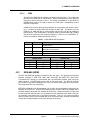
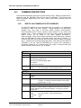
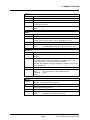
Summary of MFC-CB Direct Function Key Operation............................................................. 15
Available Flow Units ................................................................................................................ 33
Security Levels - Functions NOT Executed Per Function/Level ............................................. 40
COM1 and COM2 Available Settings ...................................................................................... 46
COM1 DB-9F Pin Designation................................................................................................. 52
COM2 DB-9M Pin Designation................................................................................................ 53
Command Summary................................................................................................................ 54
Error Messages ....................................................................................................................... 55
Status Byte Register................................................................................................................ 74
Standard Event Register ......................................................................................................... 76
Troubleshooting Checklist ....................................................................................................... 85
MFC-CB DEV1 and DEV2 Connector Pin Out ........................................................................ 89
Common MFC Connector Pin Out .......................................................................................... 91
Brooks MFC Connector Pin Out .............................................................................................. 92
Driver Output ........................................................................................................................... 92
External Drivers ....................................................................................................................... 93
DHI Authorized Service Providers ........................................................................................... 95
FIGURES
Figure 1.
Figure 2.
Figure 3.
Figure 4.
Figure 5.
Figure 6.
Figure 7.
MFC-CB Front Panel ................................................................................................................. 3
MFC-CB Rear Panel.................................................................................................................. 4
MFC-CB Internal View............................................................................................................... 5
MFC-CB Keypad Layout.......................................................................................................... 12
MFC-CB with MFC Switchbox Schematic ............................................................................... 48
Status Byte Register................................................................................................................ 74
Driver Cable Schematic........................................................................................................... 93
©2001~2007 DH Instruments, a Fluke Company
Page IV
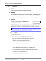
ABOUT THIS MANUAL
ABOUT THIS MANUAL
This manual provides the user with the basic information necessary to set up and operate an
MFC-CB MFC Control Box. It also includes a great deal of additional information provided to help
you optimize MFC-CB use and take full advantage of its many features and functions.
Before using the manual, take a moment to familiarize yourself with the Table of Contents structure.
All first time MFC-CB users should read Sections 1 and 2. Section 3 provides a comprehensive
description of general MFC-CB operating principles. Section 4 is for remote operation from an
external computer. Section 5 provides maintenance and calibration information. Section 6 is a quick
troubleshooting guide. Use Section 6 to troubleshoot unexpected MFC-CB behavior based on the
symptoms of that behavior.
Certain words and expressions have specific meaning as they pertain to MFC-CB. Section 7.4 is
useful as a quick reference for the definition of specific words and expressions as they are used in
this manual.
FOR THOSE OF YOU WHO “DON’T READ MANUALS”, GO DIRECTLY TO SECTION 2.3, INITIAL SETUP, TO
SET UP YOUR MFC-CB. THEN GO TO SECTION 2.4, POWER UP AND VERIFICATION. THIS WILL GET YOU
RUNNING QUICKLY WITH MINIMAL RISK OF CAUSING DAMAGE TO YOURSELF OR YOUR MFC-CB.
THEN… WHEN YOU HAVE QUESTIONS OR START TO WONDER ABOUT ALL THE GREAT FEATURES
YOU MIGHT BE MISSING, GET INTO THE MANUAL!
Manual Conventions
(CAUTION) is used in throughout the manual to identify user warnings and cautions.
(NOTE) is used throughout the manual to identify operating and applications advice and
additional explanations.
[ ] indicates direct function keys (e.g., [UNIT]).
< > indicates MFC-CB screen menus and displays (e.g., <1yes>).
©2001~2007 DH Instruments, a Fluke Company
Page v
MFC-CB™ Operation and Maintenance Manual
NOTES
©2001~2007 DH Instruments, a Fluke Company
Page vi
1. INTRODUCTION
1. I NTRODUCTION
1.1 PRODUCT OVERVIEW
MFC-CB is a two channel analog input/output device designed to set and read voltage and current
signals from analog Mass Flow Controllers (MFC) and Mass Flow Meters (MFM). A DH Instruments
MFC Switchbox may be connected to either channel allowing switching of the channel’s control
between five permanently powered channels. As an option, (8) external 12 V drivers can also be
included to excite peripheral equipment such as solenoid valves.
MFC-CB provides a local user interface via a front panel key pad and display and includes advanced
on-board functions. Remote communication capability is supported by RS232 and IEEE-488 interfaces.
MFC-CB is intended for applications where convenient local and remote control of analog MFCs and/or
MFMs is desired, for example in setting up an MFC calibration system using a DH Instruments
molbox1 or molbox RFM flow standard.
1.2 SPECIFICATIONS
1.2.1
GENERAL SPECIFICATIONS
Power Requirements 100 to 240 VAC, 50 to 60 Hz, 38 VA max. consumption
Power Supply Output ± 15 VDC @ 1 Amp max, 0.5 Amp per channel
Operating Temperature Range 15 to 35 °C
Storage Temperature Range -20 to 70 °C
Warm Up Time 1 hour for best electrical measurement specifications
Vibration Meets MIL-T-28800D
Weight 2 kg (4.4 lb)
Dimensions 8 cm H x 22.5 cm W x 20 cm D
(3.1 in. x 8.9 in. x 7.9 in.) approx.
Microprocessor Motorola 68302, 16 MHz
Communication Ports RS232 (COM1), RS232 (COM2), IEEE-488,
DHI MFC Switchbox
Electrical Connections DEV1 and DEV2: 25 pin female DSUB
CE Conformance Available. Must be specified.
Page 1
©2001~2007 DH Instruments, a Fluke Company
MFC-CB™ Operation and Maintenance Manual
1.2.2
ANALOG OUTPUT SPECIFICATIONS
VOLTAGE OUTPUT
Range 0 to 6 VDC
Uncertainty ± 0.015 %FS
Resolution 0.1 mVDC
Output Impedance (max) 100 Ω per channel
Load Impedance (min) 10 kΩ per channel
Short Circuit Protection Yes (indefinite)
CURRENT OUTPUT
Range 4 to 20 mA
Uncertainty ± 0.025 %FS
Resolution 0.4 μA
Maximum Load
Short Circuit Protection
1.2.3
500 Ω (compliance voltage: 10 VDC)
Yes (indefinite)
ANALOG INPUT SPECIFICATIONS
VOLTAGE INPUT (MEASURE AND SENSE)
Range 0 to 6 VDC
Min to Max Measurable -0.25 to 6.00 VDC
Uncertainty ± 0.015 %FS
Resolution 0.1 mVDC
Input Impedance (min) 1 MΩ
CURRENT INPUT (MEASURE)
Range 4 to 20 mA
Min to Max Measurable 4 to 20 mA
Uncertainty ± 0.025 %FS
Resolution 0.4 μA
Input Impedance
1.2.4
250 Ω
VALVE TEST POINT SPECIFICATIONS
Range +2 to +15 VDC (in reference to -15 VDC)
Accuracy ± 0.1 %FS
Resolution 0.3 mVDC
©2001~2007 DH Instruments, a Fluke Company
Page 2
1. INTRODUCTION
1.2.5
FRONT AND REAR PANELS
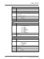
1.2.5.1
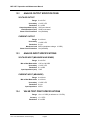
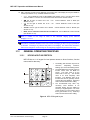
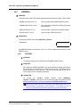
FRONT PANEL
The front panel assembly provides a 2 x 20 vacuum fluorescent display, a membrane
keypad for local user interface and a SOFT ON/OFF key.
1
3
4
2
1.
Display
2.
Multi-Function Keypad
3.
Remote Communication Indicator
4. SOFT ON/OFF Key and Indicator
Figure 1. MFC-CB Front Panel
Page 3
©2001~2007 DH Instruments, a Fluke Company
MFC-CB™ Operation and Maintenance Manual
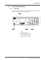
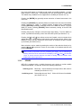
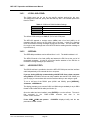
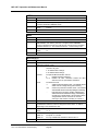
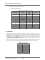
1.2.5.2
REAR PANEL
The rear panel assembly provides DEVICE1 and DEVICE2 analog input/output
channels, a 12 V drivers connection, communications interfaces and the power
connection module.
1.
Electrical power connector (IEC60320)
2.
Power ON/OFF switch
3.
Connector for 12V DRIVERS
4.
Connector for MFC Switchbox control
5.
DEVICE1 electrical input/output connection
6.
DEVICE2 electrical input/output connection
7.
COM2 connection for pass through communication
8.
COM1 connection for host computer
9.
IEEE-488 connection for host computer
Figure 2. MFC-CB Rear Panel
©2001~2007 DH Instruments, a Fluke Company
Page 4
1. INTRODUCTION
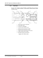
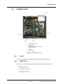
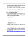
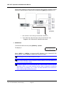
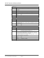
1.2.6
INTERNAL VIEW
1.
Power entry module
2.
Micro board
3.
Main board (under power supply
and micro board)
4.
Display
5.
Power supply
Figure 3. MFC-CB Internal View
1.2.6.1
DISPLAY
2 x 20 vacuum fluorescent, alpha-numeric display mounted to front panel.
1.2.6.2
POWER SUPPLY
MFC-CB has one 65 W switching power supply with three DC voltage outputs:
•
5 VDC @ 7 Amp max.
•
+15 VDC @ 2.5 Amp max.
•
-15 VDC @ 2 Amp max.
Page 5
©2001~2007 DH Instruments, a Fluke Company
MFC-CB™ Operation and Maintenance Manual
1.2.6.3
POWER ENTRY MODULE
Includes ON/OFF switch, fuse (1 Amp @ 250 VAC) and AC filter.
1.2.6.4
MICRO BOARD
The micro board supports a Motorola 68302 micro-controller, EPROM, EEPROM,
128k x 16 bit NVRAM, 8 Mbit flash memory; RS232 and IEEE-488.2
communications; keypad and display control. An I/O port controls other ports and
devices within MFC-CB.
1.2.6.5
MAIN BOARD
The main board is controlled by the micro board (see Section 1.2.6.4). The main
board supports the drivers for the 12 V external drivers, MFC/MFM voltage supply,
MFC/MFM control signal input and output.
©2001~2007 DH Instruments, a Fluke Company
Page 6
2. INSTALLATION
2. I NSTALLATION
2.1 UNPACKING AND INSPECTION
2.1.1
REMOVING FROM PACKAGING
MFC-CB is delivered, along with its standard accessories, in a corrugated container with
polyurethane inserts to hold it in place.
Remove the MFC-CB and its accessories from the shipping container and remove each item
from its protective plastic bag.
2.1.2
INSPECTING CONTENTS
Check that all items are present and have no visible damage.
An MFC-CB is delivered complete with:
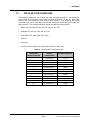
Table 1. MFC-CB Delivery List
DESCRIPTION
MFC-CB Mass Flow Control Box
Report of Calibration
PART #
401710 or 401710-CE
550100
ACCESSORIES
Operation and Maintenance Manual
550123
Power Cord (7.5 ft.)
100770 or 100770-CE
(2) MFC Cable and Connections Kit
401230 or 401230-CE
molbox1/MFC-CB Analog Calibration Cable
Drivers Connector
401256
401635 (optional)
General Accessories Disk (Important: Includes
system support software and documentation)
Page 7
102987
©2001~2007 DH Instruments, a Fluke Company
MFC-CB™ Operation and Maintenance Manual
2.2 SITE REQUIREMENTS
Install MFC-CB on any stable surface at a convenient height. The front feet are extendible so that
the unit can be inclined for easier viewing.
MFC-CB can also be mounted in a standard 19-in. rack using the optional rack mount kit
(P/N 401465). For additional information, contact your DHI Sales Representative.
If the MFC-CB will be used with an optional DHI MFC Switchbox, consider placement of the
Switchbox and the connection and disconnection of MFC cables (see Section 3.4.6, Figure 5).
2.3 INITIAL SETUP
2.3.1
PREPARING FOR OPERATION
No special preparation of MFC-CB is required prior to putting it into operation.
Connect the power cord supplied to the MFC-CB and to a power source.
2.3.2
MFC-CB TO MFC OR MFM CONNECTION
Prepare an MFC-CB to MFC or MFM cable using one of the kits provided with the MFC-CB
(see Section 7.2 for information on cable pin out) or an optional preassembled cable if you
have one.
Connect the MFC-CB to MFC/MFM cable to the DEV1 or DEV2 25 pin DSUB connection on
the MFC-CB rear panel.
If you are using an optional MFC Switchbox, connect the Switchbox to the DEV1 or DEV2
MFC-CB rear panel connection and then connect the MFC or MFM to the MFC Switchbox (see
the MFC Switchbox User’s Manual and Section 3.4.6, Figure 5).
2.4 POWER UP AND VERIFICATION
2.4.1
POWER UP
Turn ON the MFC-CB rear panel main power switch. Observe the front panel display as
MFC-CB initializes, error checks and goes to the MAIN run screen (see Section 3.1.1).
The front panel ON/OFF key controls a SOFT ON/OFF (see Section 3.1.2.3). This allows
MFC-CB’s front panel to be turned off while maintaining the power supply to devices that are
connected to it.
If the MFC-CB fails to reach the MAIN run screen, service may be required. Record the
sequence of operations and displays observed and contact a DHI Authorized Service Provider.
©2001~2007 DH Instruments, a Fluke Company
Page 8
2. INSTALLATION
2.4.2
CHECK/SET SECURITY LEVEL
MFC-CB has a security system based on user levels. By default, the security system is set to
“low”, which includes certain access restrictions, and there is no password required to change
the security level. See Section 3.4.2 and Table 4 for information on the security level system.
As part of the MFC-CB startup, set your desired security level and a password.
MFC-CB is delivered with the security level set to low to avoid inadvertent altering of critical
internal settings but with access to changing security levels unrestricted. It is recommended
that the low security level be maintained at all times and password protection be
implemented if control over setting of security levels is desired.
Page 9
©2001~2007 DH Instruments, a Fluke Company
MFC-CB™ Operation and Maintenance Manual
NOTES
©2001~2007 DH Instruments, a Fluke Company
Page 10
3. OPERATION
3. O PERATION
3.1 GENERAL MANUAL OPERATION
MFC-CB is designed to offer the optimum balance between simple, intuitive operation and the
availability of a variety of functions with a high level of operator discretion. The local operator
interface is through the front panel’s 2 x 20 character alpha-numeric display and a 4 x 4
multi-function keypad.
3.1.1
MAIN RUN SCREEN
The MFC-CB MAIN run screen is its home display that is reached on power up and from
which other functions and menus are accessed. It is the top level of all menu structures.
The MAIN run screen is where the MFC-CB is left in normal operation. It displays the set
point output, if applicable, and the measurement from the MFC or MFM as well as a variety of
additional information if desired.
3
2
→SSSSSSaUNITKaMMMMMM
D DISPLAY MODE Dn,c
10
9
1.
<→> Active channel indication in DEV1&2
DISPLAY mode (see Section 3.2.4.1). Blank if not
in DEV1&2 DISPLAY mode.
2.
<SSSSSS>: Numerical value and sign of the set
point (see Section 3.2.8).
8
3.
<a>: Indicates whether a user adjustment is being applied to the set point (see Section 3.3.5).
<a> if an adjustment is being applied, blank if no adjustment is being applied.
4.
<UNIT>: Unit of measure of the set point and measurement numerical values (see Section 3.2.2).
5.
<K>: Indicates whether a gas correction factor (K factor) is being applied (see Section 3.2.1).
<K> if a factor is being applied, blank if no factor is being applied.
6.
<a>: Indicates whether a user adjustment is being applied to the measurement value (see
Section 3.3.5). <a> if an adjustment is being applied, blank if no adjustment is being applied.
7.
<MMMMMM>: Numerical value of the measurement from the MFC or MFM.
8.
<Dn,c>: Indicates which device channel is being displayed on the top line of the display. <n> is
<1> for DEV1, <2> for DEV2. <c> indicates the current channel of the MFC Switchbox if a
Switchbox is connected to DEVn, blank if no Switchbox is in use (see Section 3.4.6).
9.
<DISPLAY MODE DATA>:
Section 3.2.4).
©2001~2002 DH Instruments, Inc
Information displayed depends on current DISPLAY mode (see
Page 11
.
MFC-CB™ Operation and Maintenance Manual
10. <D>: Indication of what is being displayed on the bottom line of the display as set by the DISPLAY
function (see Section 3.2.4). Possible indications include:
•
<→>: Current DISPLAY mode is DEV1&DEV2 (see Section 3.2.4.1) and the active device
channel is DEV2. The arrow is on the first line if the active device channel is DEV1.
•
<Σ> and far right of bottom line is Dn + Dn:
Section 3.2.4.2).
Current DISPLAY mode is SUM (see
•
<Δ> and far right of bottom line is Dn - Dn:
Section 3.2.4.3).
Current DISPLAY mode is DIF (see
•
<blank> and far right of bottom line is Dn/Dn:
Section 3.2.4.4).
•
Blank, and no characters other than Dn on bottom line: Current DISPLAY mode is CLEAN
(see Section 3.2.4.5).
Current DISPLAY mode is RATIO (see
When a number is too large to show in the allocated display space, MFC-CB
displays <********>.
MFC-CB has a SCREEN SAVER function that causes the display to dim if no key is pressed for
10 minutes. Pressing a key restores full power to the display. The screen saver activation
time can be changed or screen saving can be completely suppressed (see Section 3.4.3.1).
3.1.2
GENERAL OPERATING PRINCIPLES
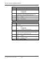
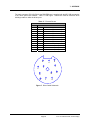
3.1.2.1
KEYPAD LAYOUT AND PROTOCOL
MFC-CB has a 4 x 4 keypad for local operator access to direct functions, function
menus and for data entry.
1
1.
The Editing and Execution keys are for
execution,
suspending
execution,
backing up in menus and editing entries.
2.
The Menu/Data keys provide access to
function menus from the MAIN run
screen. The menu name is on the
bottom half of the key. The SETUP
menu is for more frequently used
functions. The SPECIAL menu is for
functions that are not generally used as
a part of day to day operation. These keys
enter numerical values when editing.
3.
The Function/Data keys allow very
commonly used functions to be
accessed directly from the MAIN run
screen by a single keystroke. The name
of the function is on the bottom half of
the key (see Section 3.1.2.5). These keys
enter numerical values when editing.
3
2
Figure 4. MFC-CB Keypad Layout
©2001~2007 DH Instruments, a Fluke Company
Page 12
3. OPERATION
Key press confirmation is provided by both tactile and audible feedback. A single
beep confirms a valid entry. A descending two note tone signals an invalid entry.
The audible entry feedback can be suppressed or modified (see Section 3.4.3.2).
Pressing the [ENTER] key generally causes execution or forward movement in the
menu tree.
Pressing the [ESCAPE] key generally allows movement back in the menu tree and/or
causes execution to cease or suspend without changes being implemented.
Pressing [ESCAPE] repeatedly eventually returns to the MAIN run screen. From the
MAIN run screen, pressing [ESCAPE] allows momentary viewing of the MFC-CB
identification screen.
Pressing the [+/-] key changes a numerical sign when editing. From the MAIN run
screen, it provides a momentary view of the active MFC profile (see Section 3.3.1).
Pressing the [←] and [→] keys allows reverse and forward cursor movement when
editing data entry. These keys are also used to scroll through choices. When in the
MAIN run screen, they are used by the JOG function to increment the MFC set point
up and down (see Section 3.2.9).
Menu selections can be made by pressing the number of the selection directly or by
pressing [←] or [→] to place the cursor on the number of the desired selection and
pressing [ENTER].
Some screens go beyond the two lines provided by the display. This is indicated by a
flashing down arrow in the second line of the display. Press [←] and [→] to move the
cursor to access the lines that are not visible or directly enter the number of the
hidden menu choice if you know it.
3.1.2.2
SOUNDS
MFC-CB is equipped with a variable frequency tone device to provide audible
feedback and alarms. Sounds are used for the following indications:
Valid key press:
Brief beep. Choice between three frequencies or NO sound is
available (see Section 3.4.5.2).
Invalid key press:
Descending two tone “blurp”. Choice of NO sound is available
(see Section 3.4.5.2).
Page 13
©2001~2007 DH Instruments, a Fluke Company
MFC-CB™ Operation and Maintenance Manual
3.1.2.3
SOFT [ON/OFF] KEY
MFC-CB is equipped with a SOFT [ON/OFF] key and indicator LED on the bottom
left hand corner of the front panel. The purpose of the SOFT ON/OFF key is to put
MFC-CB into a dormant mode in which the display is turned OFF.
When MFC-CB is SOFT OFF, power is still supplied to DEV1 and DEV2 and the
MFC set points are maintained if the rear panel main power switch is on.
When MFC-CB is ON, the ON/OFF indicator is ON continuously. When MFC-CB is
SOFT OFF and the main power switch is on, the ON/OFF indicator blinks every
5 seconds.
When MFC-CB is SOFT OFF, receiving a remote command turns it ON.
3.1.2.4
ACTIVE DEVICE CHANNEL INDICATION
The MFC-CB active device channel (DEV1 or DEV2) is the channel whose set point
and measurement values are displayed on the top line of the MFC-CB display.
The characters on the bottom right hand corner of the display (<D1> or <D2>)
indicate which channel is currently active. The active channel is the channel that is
affected by all channel specific settings and adjustments.
Channel specific MFC-CB settings include:
•
[K] (see Section 3.2.1).
•
[UNIT] (see Section 3.2.2).
•
[MFC] (see Section 3.2.6).
•
[SETUP], <2jog> (see Section 3.3.2).
•
[SETUP], <5adj> (see Section 3.3.5).
•
[SET MFC] (see Section 3.2.8).
Regardless of which channel is currently active from the display, both DEV1 and
DEV2 are always active in the sense that their set point is maintained.
3.1.2.5
DIRECT FUNCTION KEYS SUMMARY
Local operation of MFC-CB is through the front panel, 4 x 4, pressure
sensitive keypad. To minimize the use of multi-layered menu structures, the keypad
numerical keys also provide direct access to commonly used functions. The function
accessed is labeled on the bottom half of the each key. Direct function keys are
active whenever MFC-CB is in its MAIN run screen. Table 2 summarizes the
operation of the direct function keys. See the corresponding manual sections for full
detail on each direct function.
It may be useful to keep a copy of Table 2 near the MFC-CB, especially when first
becoming acquainted with its operation.
©2001~2007 DH Instruments, a Fluke Company
Page 14
3. OPERATION
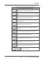
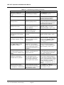
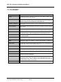
Table 2. Summary of MFC-CB Direct Function Key Operation
Direct Function Keys are active from the MAIN run screen
See corresponding manual sections for full detail
.
SETUP
0
SPECIAL
1
DEV1/2
2
MFC
3
DRIVERS
5
POWER
6
DISPLAY
7
K
9
UNIT
+/-
ENTER
SET MFC
Í
Menu of commonly used setup features including creating and editing MFC
profiles, adjusting set point jog value and display resolution.
Menu of less frequently used internal functions and settings including resets,
user preferences, internal calibration, remote interface setup and Switchbox
setup.
Toggle active device channel between DEV1 and DEV2.
Select MFC profile which sets V or mA operation and the electrical signal
to flow unit relationship.
Turn ON and OFF MFC-CB’s optional 12 V drivers.
Display the set point unaltered by K and/or adjustment values and the
valve test point.
Define the DISPLAY function for the second line of the MFC-CB display.
Choices include DEV1&2, sum, difference, ratio, 2nd unit, clean.
Set/change an MFC gas correction factor (K factor).
Set point and measure unit (electrical, %FS, flow).
View a summary of the active MFC profile for the active channel
(DEV1 or DEV2).
Enter a set point to output on the active device channel.
Î
Jog the set point up or down.
Page 15
©2001~2007 DH Instruments, a Fluke Company
MFC-CB™ Operation and Maintenance Manual
3.2 DIRECT FUNCTION KEYS
3.2.1
[K]
PURPOSE
To specify a gas measurement conversion factor, K, to be applied to the active device
channel when using and MFC or MFM calibrated with one gas to set and/or measure the
flow of another gas.
PRINCIPLE
MFCs and MFMs respond differently to different gas species due the different specific
heats of the gases and different behavior in the device. Therefore, the calibration of an
MFC or MFM with one gas may not be valid with another gas. MFC manufacturers often
provide gas conversion factors, known as K factors, to convert an MFC from the gas it
was calibrated with to another gas.
The MFC-CB’s K function allows the device manufacturer’s K factor to be entered and
applied to the active channel so that set points and measurement values are
automatically adjusted by the K factor. This feature can be useful when using an MFC
calibrated with one gas to control or measure a different gas.
MFC-CB applies the K factor only when the unit of measure is a flow unit. When the unit
of measure is an electrical unit (V or mA) or %FS, the K factor has no effect.
See Section 7.1.1 for details on the calculations used to apply the K factor.
When using MFC-CB in conjunction with a molbox/molbloc mass flow standard to calibrate
or verify an MFC, the K factor function of the MFC-CB is NOT normally used. K factors are
applied to the molbox measured flow to simulate a process gas with a surrogate gas (see
the molbox Operation and Maintenance manual Section concerning K factors).
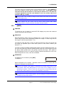
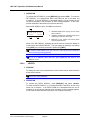
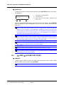
OPERATION
To enable a gas conversion factor press [K] from the
MAIN run screen. The display is:
If <2off> is selected, no conversion factor will
be applied. If <1on> is selected, the next screen is:
©2001~2007 DH Instruments, a Fluke Company
Page 16
K factor: (1.0000)
1off 2on
D1
K factor:
1.00000
D1
3. OPERATION
The value of the gas conversion factor can be edited as desired. Press [ENTER] to
return to the MAIN run screen with the entered K factor active. The K factor is only
used if the current unit of measure is a flow unit (see Section 3.2.2). The letter <K>
is always appended to the flow unit indication in the run screens when the K
function is ON (e.g., sccmK).
Turning K ON or OFF or making a change to the K factor value resets the active device
channel output to zero.
K factor ON/OFF and the K factor value are device channel specific (DEV1, DEV2).
Settings made for one device channel do not affect the other channel.
3.2.2
[UNIT]
PURPOSE
To specify the unit of measure in which MFC-CB displays set points and measured
values on the active device channel.
PRINCIPLE
MFC-CB operates in either volts (V) or milliamps (mA). It also converts V or mA to flow
values using a simple linear relationship between the voltage or current range and the
flow range in a flow unit (see Section 7.1.2).
The electrical mode and range in which to operate as well as the flow unit and the flow
unit range are specified by the active MFC profile for each device channel (see
Section 3.3.1).
The units of measure available to display MFC-CB set points and measurements are V or
mA, %FS and a flow unit if the MFC profile specifies a flow unit. MFC profiles #1 and #2
are factory default profiles that do not specify a specific flow range. MFC profile #1
specifies operation from 0 to 5 V and MFC profile #2 specifies operation from 4 to 20 mA.
When using profile #1 or #2, no flow unit is available.
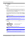
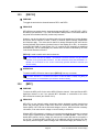
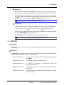
OPERATION
To change the unit of measure press [UNIT].
The display is:
1V 2%FS 3sccm
Select the desired unit of measure. Operation returns to the MAIN run screen with the
display unit changed to the selected unit.
The flow unit available under [UNIT] is determined by the MFC profile active for the
device channel. When using MFC profile #1 or #2, no flow unit is available as none is
specified by the profile. To work in a flow unit, set up and use a custom MFC profile (see
Section 3.3.1). MFC profile #1 is 0 to 5 V. MFC profile #2 is 4 to 20 mA.
The UNIT function is device channel specific. The unit setting for one device channel does
not affect the other device channel.
Page 17
©2001~2007 DH Instruments, a Fluke Company
MFC-CB™ Operation and Maintenance Manual
3.2.3
[POWER]
PURPOSE
To display of the set value unaltered by K or adjustment values and to display the valve
test point.
PRINCIPLE
The electrical value actually output by MFC-CB in response to a set point entry may be
different from the set point value due to the application of a K factor (see Section 3.2.1)
and/or an adjustment factor (see Section 3.3.5). See Section 7.1.1 for details on the
calculation of the actual set point. The [POWER] screen displays the actual electrical
value output by MFC-CB in response to a set point input.
Some mass flow controllers allow access to a valve test point voltage measurement to
assist in troubleshooting the MFC’s operation. MFC-CB can measure and display the
valve test point voltage. A display of this value is available by pressing the [POWER]
function key.
The valve test point is always in Volts (V), even for an MFC whose set point and flow
measurement are in current (mA.).
For MFC-CB to display the valve test point, the MFC being used must support valve test
point measurement and be properly connected to the MFC-CB. Refer to the MFC
manufacturer’s documentation for information on the valve test point and to Section 7.2
for information on MFC-CB DEV1 and DEV2 connections and pin outs.
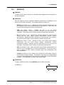
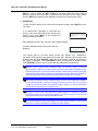
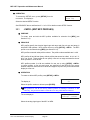
OPERATION
To display the set point and MFC valve test point press [POWER] from the run screen.
The display is:
Set point: 2.0000 V
Valve: 3.475 V
D1
1.
Actual set point for active device channel.
2.
Active device channel indicator.
3.
Current valve test point reading.
2
Press [ESCAPE] or [ENTER] to return to the MAIN run screen.
The POWER run screen displays the actual MFC set point which may be different from the
entered set point due to the application of a K factor and/or adjustment factors (see
Section 7.2).
The POWER screen is a run screen from which other functions can be accessed.
For example, while in the POWER screen, press [SET MFC] to change the MFC set point,
[DEV1/2] to change device channels or [MFC] to select a new MFC profile.
©2001~2007 DH Instruments, a Fluke Company
Page 18
3. OPERATION
3.2.4
[DISPLAY]
PURPOSE
To select, from a variety of choices, the information that is displayed on the second line of
the MFC-CB display.
PRINCIPLE
MFC-CB supports a variety of advanced DISPLAY functions that are displayed on the
bottom line of the MFC-CB display. The available DISPLAY functions are:
•
DEV1&2 (see Section 3.2.4.1): Displays both device channels simultaneously with
DEV1 always on the top line and DEV2 always on the bottom line. This function can
be useful when working with two MFCs simultaneously.
•
SUM (see Section 3.2.4.2):
Displays the sum of the two device
channel measurements. Requires that DEV1 and DEV2 be set to the same unit
of measure. This function can be useful to view the combined flow of two MFCs.
•
DIF (see Section 3.2.4.3): Displays the difference between the inactive device
channel and the active device channel measurements (inactive channelactive channel). Requires that DEV1 and DEV2 be set to the same unit of measure.
This function can be useful to view the difference between two flow rates.
•
RATIO (see Section 3.2.4.4): Displays the ratio of the inactive device channel
measurement and the active device channel measurement (inactive
channel/active channel). Requires that DEV1 and DEV2 be set to the same unit
of measure. This function can be useful to view the ratio of two flow rates.
•
UNIT (see Section 3.2.4.5): Allows the current device channel measurement to be
viewed in two of its available units of measure simultaneously. This function can be
used to display the MFC sensor’s electrical output and corresponding flow
rate simultaneously.
•
CLEAN (see Section 3.2.4.6): Blanks out the second line of the display except for
the active device channel indicator. This function is used when only a simple display
of set point and measurement for the active device channel with no other information
is wanted. The CLEAN DISPLAY is MFC-CB’s default display.
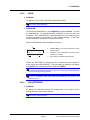
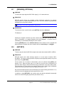
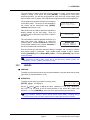
OPERATION
To select a DISPLAY function, press [DISPLAY] from the MAIN run screen.
The display is:
1DEV1&2 2sum 3dif
4ratio 5unit 6clean
2
Page 19
©2001~2007 DH Instruments, a Fluke Company
MFC-CB™ Operation and Maintenance Manual
The cursor is on the active DISPLAY function. Selecting a DISPLAY function returns to
the run screen with the selected DISPLAY function active.
See PRINCIPLE above and Sections 3.2.4.1 through 3.2.4.6 for details on each
DISPLAY function.
The default DISPLAY function is CLEAN which causes the second line of the display to be
empty except for the active device channel indicator at the far right (see Section 3.1.1).
3.2.4.1
<1DEV1&2>
PURPOSE
To view both MFC-CB device channels simultaneously.
See Section 3.2.4, PRINCIPLE.
OPERATION
To activate the DEV1&2 DISPLAY, press [DISPLAY] and select <1DEV1&2>.
Selecting <1DEV1&2> returns to the MAIN run screen with the DEV1&2
DISPLAY active.
With the DEV1&2 DISPLAY active, the MAIN run screen is:
Æ 4.0000 V
2.0000 V
3.9985
2.0036
1.
Active device channel indicator.
2.
Standard set point and measurement line for
DEV1.
3.
Standard set point and measurement line for
DEV2.
DEV1 is always on the top line and DEV2 is always on the bottom line,
regardless of which device channel was active when the DEV1&2 DISPLAY
was selected. The device channel indicator <Æ> indicates which device channel
is active for set point changes and other functions. Press [DEV1/2] to toggle the
active device channel indicator between DEV1 and DEV2.
To go to a DISPLAY other than DEV1&2, press [DISPLAY] and make a new
DISPLAY choice.
©2001~2007 DH Instruments, a Fluke Company
Page 20
3. OPERATION
3.2.4.2
<2SUM>
PURPOSE
To display the sum of DEV1 and DEV2 measurement values.
See Section 3.2.4, PRINCIPLE.
OPERATION
To activate the SUM DISPLAY, press [DISPLAY] and select <2sum>. To reach
the SUM DISPLAY, it is required that DEV1 and DEV2 be set in the same unit
of measure. If the SUM DISPLAY is attempted while the unit of measure on the
two device channels is not the same, an error message displays. In this case,
set both channels to the same unit of measure and retry.
With the SUM DISPLAY active the MAIN run screen is:
1.
Standard MAIN run screen top line for the active
device channel.
2.
Indication of sum calculation, the active device
channel is to the right.
3.
Sum of DEV1 and DEV2 measurements.
100.00 sccm 99.998
ε 150.005
D1+D2
2
While in the SUM DISPLAY, changing the unit of measure causes the display to
revert back to the CLEAN DISPLAY. This can happen by making a unit change
using [UNIT] or by selecting a new MFC profile using [MFC].
To switch the SUM DISPLAY from D2 + D1 to D1 + D2 and vice versa, change the
active channel by pressing [DEV1/2].
To go to a DISPLAY other than SUM, press [DISPLAY] and make a new
DISPLAY choice.
3.2.4.3
<3DIF>(DIFFERENCE)
PURPOSE
To display the difference between the measurement of the inactive device
channel and of the active device channel.
See Section 3.2.4, PRINCIPLE.
Page 21
©2001~2007 DH Instruments, a Fluke Company
MFC-CB™ Operation and Maintenance Manual
OPERATION
To activate the DIF DISPLAY, press [DISPLAY] and select <3dif>. To reach the
DIF DISPLAY, it is required that DEV1 and DEV2 be set in the same unit
of measure. If the DIF DISPLAY is attempted while the unit of measure on the
two device channels is not the same, an error message appears. In this case,
set both channels to the same unit of measure and retry.
With the DIF DISPLAY active, the MAIN run screen is:
100.00 sccm 99.998
D2-D1
Δ 0.035
1.
Standard MAIN screen top line for the active
device channel.
2.
Indication of difference calculation formula, the
active device channel is to the right.
3.
Difference of the inactive and active device
channel measurements.
2
While in the DIF DISPLAY, changing the unit of measure causes the display to
revert back to the CLEAN DISPLAY. This can happen by making a unit change
using [UNIT] or by selecting a new MFC profile using [MFC].
To switch the DIF DISPLAY from D2 – D1 to D1 – D2 and vice versa, change the
active channel by pressing [DEV1/2].
To go to a DISPLAY other than DIF, press [DISPLAY] and make a new
DISPLAY choice.
3.2.4.4
<4RATIO>
PURPOSE
To display the ratio of the measurements of the inactive device channel and the
active device channel.
See Section 3.2.4, PRINCIPLE.
OPERATION
To activate the RATIO DISPLAY, press [DISPLAY] and select <4ratio>.
To reach the RATIO DISPLAY, it is required that DEV1 and DEV2 be set in the
same unit of measure. If the RATIO DISPLAY is attempted while the unit of
measure on the two device channels is not the same, an error message appears.
In this case, set both channels to the same unit of measure and retry.
©2001~2007 DH Instruments, a Fluke Company
Page 22
3. OPERATION
With the RATIO DISPLAY active, the MAIN run screen is:
2.5000 V 2.5003 V
1.0036:1
D2/D1
1.
Standard MAIN screen top line for the active
device channel.
2.
Indication of ratio calculation formula, the
active device channel is to the right.
3.
Ratio of the inactive and active device channel
measurements.
2
While in the RATIO DISPLAY, changing the unit of measure causes the display
to revert back to the CLEAN DISPLAY. This can happen by making a unit
change using [UNIT] or by selecting a new MFC profile using [MFC].
To switch the RATIO DISPLAY from D2/D1 to D1/D2 and vice versa, change the
active channel by pressing [DEV1/2].
To go to a DISPLAY other than RATIO, press [DISPLAY] and make a new
DISPLAY choice.
3.2.4.5
<5UNIT>
PURPOSE
To display the measurement of the active device channel in two different units
of measure.
See Section 3.2.4, PRINCIPLE.
OPERATION
To activate the UNIT DISPLAY, press [DISPLAY] and select <5unit>. The unit
of measure to use for the second line of the MAIN run screen display is
then selected. The unit selection process is identical to that of the [UNIT]
function key (see Section 3.2.2). Once the unit has been selected, operation
returns to the MAIN run screen with the UNIT DISPLAY active.
With the UNIT DISPLAY active the MAIN run screen is:
2.5000 V 2.5003 V
= 500.06 sccm
2
Page 23
1.
Standard MAIN run screen top line.
2.
Alternate unit of measure selected for UNIT
DISPLAY.
3.
Equivalent of the measurement in the
alternate unit of measure.
©2001~2007 DH Instruments, a Fluke Company
MFC-CB™ Operation and Maintenance Manual
When the UNIT DISPLAY is selected on the active device channel, the UNIT
DISPLAY is also used for the other device channel if possible. When changing
device channels, the same unit types are used. If the UNIT DISPLAY setting on
the active device channel was for “electrical unit = flow unit”, the display of the
new channel will be “electrical unit = flow unit”. If a required unit type is not
available (for example there is no flow unit because the current MFC profile is a
factory default profile) the display defaults to the CLEAN DISPLAY.
To go to a DISPLAY other than UNIT, press [DISPLAY] and make a new
DISPLAY choice.
3.2.4.6
<6CLEAN>
PURPOSE
To activate the CLEAN DISPLAY.
See Section 3.2.4, PRINCIPLE.
OPERATION
To activate the CLEAN DISPLAY press [DISPLAY] and select <6clean>.
Selecting <6clean> returns to the MAIN run screen with the CLEAN
DISPLAY active.
With the CLEAN DISPLAY active, the MAIN run screen is:
5.0000
V
4.9984
D1
1.
Standard MAIN run screen top line.
2.
“Clean” second line.
2
To go to a DISPLAY other than CLEAN, press [DISPLAY] and make a new
DISPLAY choice.
©2001~2007 DH Instruments, a Fluke Company
Page 24
3. OPERATION
3.2.5
[DEV1/2]
PURPOSE
To toggle the active device channel between DEV1 and DEV2.
PRINCIPLE
MFC-CB has two analog device channels designated DEVICE 1 and DEVICE 2 (DEV1
and DEV2) (see Section 3.1.2.4). Both channels are always active in the sense that their
set points are maintained and they continuously measure.
However, one device channel is considered active from the standpoint of various displays
and as the device channel to which a variety of channel specific settings, adjustments
and functions apply. The active device channel is always indicated by the active device
channel indicator at the bottom right hand corner of the display (D1 or D2). An exception
is the DEV1&2 DISPLAY (see Section 3.2.4.1) in which the two channels are displayed
simultaneously, one on each display line, and the active channel is indicated by an arrow
in the far left character of the line.
[DEV1/2] is used to switch active device channels.
Do not confuse the MFC-CB DEVICE 1 and DEVICE 2 channels with the five (5) channels
available on the optional MFC Switchbox. The MFC Switchbox allows MFC-CB DEVICE 1 or
DEVICE 2 to be directed to one of five continuously powered Switchbox channels (see
Section 3.4.6).
OPERATION
To switch the MFC-CB active channel press [DEV1/2] from any run screen.
If an MFC Switchbox is connected and active on MFC-CB DEV1 or DEV2, use [MFC] to
switch channels on the Switchbox (see Sections 3.2.6 and 3.4.6).
3.2.6
[MFC]
PURPOSE
To select the MFC profile for the active MFC-CB device channel. Also specifies the MFC
Switchbox channel to use if an optional MFC Switchbox is connected to the active
MFC-CB device channel (see Section 3.4.6).
PRINCIPLE
MFC-CB is a two channel analog input/output device designed to apply electrical set
points and read back sensor output from mass flow controllers (MFC) and mass flow
meters (MFM). MFC-CB can set and read voltage or current. When it has the necessary
information, it can also convert voltage or current linearly to a flow unit.
Whether MFC-CB operates in voltage or current and how electrical values are converted
to flow values is determined by information contained in an MFC Profile. There are two
default MFC profiles, one for voltage (#1) and one for current (#2) that do not specify a
unit of flow. Customized MFC profiles (up to 97 additional) may be created by the user
that specify electrical signal, electrical range, flow unit and flow range (see Section 3.3.1).
Page 25
©2001~2007 DH Instruments, a Fluke Company
MFC-CB™ Operation and Maintenance Manual
[MFC] is used to select the MFC Profile for the active MFC-CB device channel.
When an optional MFC Switchbox is connected and activated on the current device
channel, [MFC] also specifies which Switchbox channel to use (see Section 3.4.6).
OPERATION
To select the MFC profile for the active MFC-CB device channel, press [MFC] from the
run screen.
If an optional MFC Switchbox is connected and
active on the active MFC-CB device channel (see
Section 3.4.6), when [MFC] is first pressed the
screen prompts the operator:
Select MFC Switchbox
channel: 1
D1
Enter Switchbox channel <1>, <2>, <3>, <4> or <5> as desired.
If an MFC Switchbox is NOT being used, the first
display is:
Select MFC profile:
#3
The number refers to the MFC profile number (see Section 3.3.1, PRINCIPLE).
The profile number shown is the last profile number used. Edit the profile number to the
desired profile and press [ENTER]. When the profile number is entered, a summary of
the profile is displayed. Press [ESCAPE] to back up and select a different profile.
Press [ENTER] to return to the run screen with the selected MFC profile active.
MFC-CB cannot operate with a different type of electrical signal on its two
device channels. Selecting an MFC profile whose electrical signal is different for the
electrical signal active on the other channel prompts a warning that confirming the profile
will cause the other channel to switch to the default factory profile that specifies the
same electrical signal as the profile being selected (#1 for voltage, #2 for current).
MFC profiles #1 and #2 are factory default profiles. #1 is for 0 to 5 V operation and #2 is
for 4 to 20 mA operation. These do not support operation in a flow unit. If you have not
yet set up any custom profiles, use profile #1 or #2 to operate. To set up custom MFC
profiles that include flow units, see Section 3.3.1.
Pressing [+/-] from a run screen causes an instant display of a summary of the MFC
profile that is active on the active device channel. This can be used for a quick check of
the characteristics of the currently active MFC profile.
MFC profile selections made using [MFC] are device channel specific. The set point
entered on one device channel does not affect the other channel.
©2001~2007 DH Instruments, a Fluke Company
Page 26
3. OPERATION
3.2.7
[DRIVERS] (OPTIONAL)
PURPOSE
To control the output signals of MFC-CB’s eight (8), 12 V external drivers.
PRINCIPLE
MFC-CB external drivers are available to drive peripheral equipment, for example
solenoid valves, in a system that includes MFC-CB. The driver electrical connections are
available from a rear panel connector.
See Section 7.3 for driver specifications and pin outs.
OPERATION
To access the driver control function press [SETUP] and select <4drivers>.
The display is:
External drivers: 1
2 3 4 5 6 7 8
Pressing the keypad numerical key driver number turns that driver ON and OFF with
either a momentary or a toggled response (see next paragraph). An active driver is
indicated by <*> immediately following the driver number.
Pressing [ENTER] while in the <External drivers> menu causes a menu to appear that
allows selection of whether the driver actuation will be <1momentary> or <2toggle>.
3.2.8
[SET MFC]
PURPOSE
To enter a set point value for MFC-CB to output on the active device channel (DEV1 or DEV2).
PRINCIPLE
MFC-CB outputs and reads electrical signals on its two device channels, DEV1
and DEV2. The value to output (the MFC set point) can be specified remotely or by front
panel entry using [SET MFC].
The set points unit of measure is determined by the unit selected using [UNIT] (see
Section 3.2.2). When set point entry is in a flow unit, the flow unit is converted to an
electrical value using the electrical and flow range information in the active MFC profile.
The conversion of a flow value to an electrical value is by a simple linear relationship
between the flow range and the electrical range (see Section 7.1.2).
Set point and measured values can be affected by the K factor setting (see Section 3.2.1)
and/or the use of the adjustment function (see Section 3.3.5).
In addition to using [SET MFC], the set point value can also be adjusted incrementally
from the run screen using the jog function (see Section 3.2.9).
Page 27
©2001~2007 DH Instruments, a Fluke Company
MFC-CB™ Operation and Maintenance Manual
OPERATION
To enter a set point for the active device channel, press [SET MFC] from the run screen.
The display is:
1.
Enter set point:
1.0000 V
D1
Active device channel indicator.
2.
Unit of measure.
3.
Entry field for set point value. Defaults to last
entry or zero.
2
Use the numerical and editing keys to enter the set point value desired. Press [ENTER]
when the desired set point is displayed to return to the run screen with the new set
point active.
If the set point value entered results in an out of range electrical output value, MFC-CB
displays an error message. Press [ESCAPE] or [ENTER] to return to the <Enter set
point:> screen and enter a valid set point value. Consider that a set point that appears
valid may cause an out of range condition due to the application of a K factor or
adjustment value (see Sections 3.2.1, 3.3.5 and 7.1.1).
If the active MFC profile is not a controller, an error message appears when a set point
value is entered. To enter set point values, use MFC profile #1 (for V) or #2 (for mA) or
set up and select an MFC profile for a controller (see Section 3.3.1).
The set point value may be adjusted incrementally directly from the run screen using the
[←] or [→] keys to “jog” the set point (see Section 3.2.9).
To view a summary of the active MFC profile, press [+/-] from the run screen.
Set point entries are device channel specific. The set point entered on one device channel
does not affect the other device channel.
3.2.9
[←] AND [→] (JOG MFC SET POINT)
PURPOSE
To adjust (jog) the MFC set point by a small value directly from the run screen, rather
than by entering a new set point using [SET MFC].
See Section 3.3.2 for information on setting the jog increment values.
©2001~2007 DH Instruments, a Fluke Company
Page 28
3. OPERATION
PRINCIPLE
MFC-CB set points are entered using [MFC]. In some cases, it can be useful to adjust or
trim the set point slightly, directly from the run screen without going through set point entry.
The MFC-CB jog function makes it easy to adjust the set point slightly. Pressing the [←]
or [→] key when in the MAIN run screen causes the set point value to increase or
decrease by the amount specified in [SETUP], <2jog> (see Section 3.3.2).
Use [SET MFC] to enter a new set point (see Section 3.2.8).
OPERATION
The MFC set point value can be jogged from the MAIN run screen or from the POWER screen.
To jog the set point, press [←] to decrease the value or [→] to increase the value.
Each time [←] or [→] is pressed, the set point value is adjusted up or down by the value
specified in [SETUP], <2jog> (see Section 3.3.2).
Use [SET MFC] to enter a completely new set point (see Section 3.2.8).
See Section 3.3.2 for information on setting the jog increment values.
3.3 [SETUP]
PURPOSE
To access a menu of commonly used MFC-CB functions and features that DO NOT have direct
function keys.
PRINCIPLE
The [SETUP] key accesses a menu of commonly used MFC-CB functions and features that do
NOT have direct function keys. These functions include:
•
MFC (see Section 3.3.1):
To create, store and edit the MFC profiles available for selection
from [MFC].
•
jog (see Section 3.3.2):
To adjust the set point jog increment value.
•
res (see Section 3.3.3):
To adjust the resolution
measurement displays.
•
flowU (see Section 3.3.4):
To customize the flow unit choices available when setting up
MFC profiles.
•
adj (see Section 3.3.5):
To adjust the MFC set points and/or measurements by an adder
and/or a multiplier.
Page 29
of
MFC-CB
set
point
and
©2001~2007 DH Instruments, a Fluke Company
MFC-CB™ Operation and Maintenance Manual
OPERATION
To access the SETUP menu, press [SETUP] from the
run screen. The display is:
1MFC 2jog 3res
4flowU 5adj
Select the desired SETUP function.
See PRINCIPLE above and Sections 3.3.1 to 3.3.5 for details on each SETUP function.
3.3.1
<1MFC> (EDIT MFC PROFILES)
PURPOSE
To create, store and edit the MFC profiles available for selection from [MFC] (see
Section 3.2.8).
PRINCIPLE
MFC profiles specify the electrical signal type and range and flow unit type and range in
which MFC-CB operates. MFC profiles are set up using [SETUP], <1MFC>. The MFC
profile to use is selected using [MFC] (see Section 3.2.6).
MFC profiles are stored under profile numbers. The profile numbers available are 1 to 99.
MFC profiles #1 and #2 are factory default profiles that cannot be edited. #1 is 0 to 5 V,
#2 is 4 to 20 mA. These profiles do not specify a flow unit or range and therefore do not
allow operation in a unit of flow.
MFC profiles number 3 to 99 are available for user set up using [SETUP], <1MFC>.
In custom profiles, a flow unit and range are specified so that MFC-CB can convert
between electrical values and flow values and support set point entry and measurement
display in a flow unit.
OPERATION
To create or edit an MFC profile, press [SETUP], <1MFC>.
Edit MFC profile:
# 3
The display is:
Select the profile number to edit and press [ENTER].
MFC profiles #1 and #2 are factory default profiles for working in electrical or %FS
units only. They cannot be edited. Profile #1 is 0 to 5 V, profile #2 is 4 to 20 mA.
The next display is:
Signal type:
1voltage
Select the analog signal type of the MFC or MFM.
©2001~2007 DH Instruments, a Fluke Company
Page 30
2current
3. OPERATION
The next display is used to enter the full scale voltage or current. Enter the full scale
voltage or current of the device and press [ENTER]. If configuring a current (mA)
electrical type MFC, you will also be prompted to enter the 0 flow current output value
which must be 4 mA or greater. MFC-CB does not support mixed current/voltage MFCs.
The next selection specifies the flow unit of measure
for this MFC profile. The choice of units available in
this screen can be customized using [SETUP],
<4flowU> (see Section 3.3.4).
After the flow unit of measure has been selected the
display prompts for the flow range. Enter the
numerical value of full scale of the MFC or MFM in
the flow unit.
1sccm 2slm 3mg/s
4mol/s 5sm3h 6scfh
Enter range:
100.00 sccm
The next selection specifies whether the device is a
mass flow meter only (MFM) or a mass flow
controller (MFC). Choose <1measure> if the device
for this profile measures only, choose <2control> if
the device measures and controls flow.
Once the device type has been selected, editing is complete and a prompt to edit the
next profile number is presented. Enter another profile number to edit if desired.
Pressing [ESCAPE] goes to <Select MFC profile:>. Pressing [ESCAPE] again returns
to the run screen.
To clear/reset all MFC profiles, except the #1 and #2 factory default profiles, use
[SPECIAL], <1reset>, <3MFC> (see Section 3.4.1.3).
3.3.2
<2JOG>
PURPOSE
To adjust the increment by which one key press adjusts the set point when the set point
jog function is used (see Section 3.2.9).
OPERATION
To adjust the set point jog function increment, press
[SETUP], <2jog>. The display is:
Set jog step:
0.10 %FS < and > D1
Use the [←] and [→] keys to adjust the value. Maximum is 1.00 %FS. Minimum is
0.01 %FS. The FS value is the full scale specified in the active MFC profile (see
Section 3.3.1). Press [ENTER] to return to the run screen with the jog value active.
The jog increment setting is device channel specific (DEV1, DEV2). Changing the jog
increment value set for one device channel does not affect the other device channel.
Page 31
©2001~2007 DH Instruments, a Fluke Company
MFC-CB™ Operation and Maintenance Manual
3.3.3
<3RES> (RESOLUTION)
PURPOSE
To set the display resolution of MFC-CB set point and measurement displays.
PRINCIPLE
The resolution with which the MFC-CB displays set points and measurements can
be adjusted. This feature can be used to reduce the display resolution when lower
precision measurements are being made and additional digits might confuse or distract
the operator.
The desired resolution is calculated based on full scale of the active MFC profile (see
Section 3.3.1), then rounded to the furthest digit to the right (e.g., resolution of 0.1 %FS
on a 5 V MFC is 0.001 V).
The default resolution setting is 0.01 %FS. The resolution setting does not affect the
resolution of information transmitted remotely. Remote information always has
maximum resolution.
OPERATION
To access the RESOLUTION function, press
[SETUP], <3res>. The display is:
Display resolution:
0.01% FS < and > D1
Press the [←] or [→] key to set the desired level of resolution. Maximum is 1.00 %FS.
Minimum is 0.01 %FS. The FS value is the full scale specified by the active MFC profile
(see Section 3.3.1). Press [ENTER] to return to the MAIN run screen with the selected
display resolution.
The resolution setting is device channel specific (DEV1, DEV2). The resolution set for one
device channel does not affect the other device channel.
3.3.4
<4FLOWU> (FLOW UNITS)
PURPOSE
To customize the selection of flow units that are available when editing MFC profiles (see
Section 3.3.4).
PRINCIPLE/OPERATION
The unit selection screen presented when editing MFC profiles provides a choice of six
different flow units of measure. The units that are available by default are the six
indicated in Section 3.2.2. MFC-CB supports many other units. These other units can be
made available by customizing the MFC profile unit selection screen.
To customize the MFC profile unit selection screen,
press [SETUP], <4flowU>. The display is:
©2001~2007 DH Instruments, a Fluke Company
Page 32
Set up user unit #6
3. OPERATION
<#6> corresponds to the sixth of the six available
selections in the MFC profile unit screen. Enter the
number of the selection that you would like
to change. The display becomes:
Flow unit type: 1std
3vlm 4none
Select the type of flow unit desired (see Table 3). Then select the desired unit.
Table 3. Available Flow Units
<1std>
<1mol/s>
<2kg/s>
<3mg/s>
<4slm>
<5sccm>
<6scfm>
<7scfh>
<8slh>
<9sm3h>
<2vlm>
<1ccm>
<2lm>
<3lh>
<4m3h>
<6cfm>
<7cfh>
<3none>
This selection causes the
position for this unit to be
blank.
<1std> units are units of mass flow. <2vlm> units are units of volume flow.
3.3.5
<5ADJ> (ADJUSTMENT)
PURPOSE
To apply an adder and/or multiplier to the MFC-CB set point and/or measurement.
PRINCIPLE
The adjustment function gives the user the capability to mathematically adjust the set
point output and the value measured back by MFC-CB. This is accomplished by setting
an adder and/or a multiplier.
There are separate adders and multipliers for the set point and for the measurement.
The set point adder and multiplier alter the set point actually output by
MFC-CB following:
actual set point = (requested and displayed set point * multiplier) + adder
The measurement adder and multiplier alter the value measured by MFC-CB as follows:
displayed measurement = (actual measurement *multiplier) + adder
The adder is a constant that is always expressed in terms of %FS. The full scale value is
determined by the active MFC profile (see Section 3.3.1). The multiplier is dimensionless.
If a K factor is active (see Section 3.2.1), the adder and multiplier are applied after the K
factor is applied. However, if the unit of measure is electrical or %FS, the K factor is
not used.
Page 33
©2001~2007 DH Instruments, a Fluke Company
MFC-CB™ Operation and Maintenance Manual
The adjustment function is intended to allow MFC-CB to correct an MFC or MFM that is
connected to it by making an offset and/or slope adjustment automatically.
For additional information on the calculations used by the adjustment function and how
they interact with other MFC-CB calculations, see Section 7.1.1.
Do NOT use the adjustment function to calibrate MFC-CB set point and
measurement signals. The internal calibration function should be used for this purpose
(see Section 5.2).
OPERATION
To access the adjustment function
[SETUP], <5adj>. The display is:
press
Signal to adjust:
1set 2measure
D1
Select <1set> to adjust the set point adder and/or multiplier or <2measure> to adjust the
measurement adder and/or multiplier.
The next display is (an <s> or <m> precedes the active
device channel indicator to indicate set or measure):
Adder: 0.000 %FS
Multiplier:1.0000
Edit the values as desired. Press [ENTER] to return to the run screen with the edited
adder and multiplier values applied.
An indicator appears on the MAIN run screen whenever an adder and/or multiplier
is active. The indication is by an <a> just to the right of the set point value for set point
adjustments and an <a> just to the left of the measured value for measurement
adjustments (see Section 3.1.1 for detailed run screen information).
The adjustment function flow adder and multiplier, if different from 0 and 1, alter the set
points output and readings made by the MFC-CB. The adjustment function is always
"ON", even if MFC profiles are changed.
Take care not use adders and/or
multipliers unintentionally.
Making a change to an adjustment function value sets the affected device channel output
to zero.
The adjustment function is device channel specific (DEV1, DEV2). Adders and multipliers
are set independently for the two device channels and the adders or multipliers on one
channel have no effect on the other channel.
©2001~2007 DH Instruments, a Fluke Company
Page 34
3. OPERATION
3.4 [SPECIAL]
PURPOSE
To access menu of MFC-CB functions and settings that are less commonly or not normally used
in regular operation.
PRINCIPLE
The [SPECIAL] key accesses a menu of MFC-CB functions and settings that are less commonly
or not normally used in regular operation. These functions include:
•
reset (see Section 3.4.1):
Access and execute various reset options.
•
level (see Section 3.4.2):
View and change security protection of MFC-CB functions.
•
prefs (see Section 3.4.3):
View and set user operational preferences including
screen saver, keypad sounds, time and ID features.
•
cal (see Section 3.4.4):
View and edit MFC-CB electrical signal calibration
coefficients and calibration date.
•
remote (see Section 3.4.5):
Set up/modify MFC-CB RS232 (COM1, COM2) and
IEEE-488 interfaces. Test RS232 ports.
•
xbox (see Section 3.4.6):
Activate an optional MFC Switchbox on a device channel
(DEV1, DEV2).
•
log (see Section 3.4.7):
View and reset the MFC-CB incident log.
OPERATION
To access the SPECIAL menu, press [SPECIAL] from the MAIN run screen.
The display is:
1reset 2level 3prefs
4cal 5remote 6xbox
7log
Select the desired function.
See PRINCIPLE above and Sections 3.4.1 to 3.4.7 for details on each SPECIAL function.
Some screens (i.e., the SPECIAL menu) go beyond the two lines provided by the display. This is
indicated by a flashing down arrow in the second line of the display. Press the [←] and [→] keys
to move the cursor to access the lines that are NOT visible or directly enter the number of the
hidden menu choice if you know it.
Page 35
©2001~2007 DH Instruments, a Fluke Company
↓
MFC-CB™ Operation and Maintenance Manual
3.4.1
<1RESET>
PURPOSE
To reset various MFC-CB settings to default or factory values.
PRINCIPLE
MFC-CB stores user definable settings in non-volatile memory. The reset menu allows
the user to selectively or completely reset these values to factory defaults. Resets clear
settings that the user may have made, and should be used only to restore the MFC-CB to
a known state. MFC-CB will go through its reboot routine after any type of reset
is executed.
OPERATION
To access the reset choices press [SPECIAL] and
select <1reset>. The display is:
1sets 2units 3MFC
4cal 5all
Select the desired reset. After confirmation, the reset occurs. A reset always puts the
MFC-CB through its power up routine as if power had been turned OFF and back ON.
See Sections 3.4.1 through 3.4.5 for detailed information on the specific reset choices.
RESET functions change user settings that affect set point and read signals. If not used
properly, resetting can cause out of tolerance measurements. RESET functions should
only be used by qualified personnel with reference to this manual.
3.4.1.1
<1SETS>
PURPOSE/OPERATION
To access Reset - Sets, press [SPECIAL], <1reset>, <1sets>.
Reset - Sets clears and sets to default the following user settings:
•
DISPLAY mode to CLEAN (see Section 3.2.4.6).
•
Device channel selection to DEV1 (see Section 3.1.2.4).
•
K factor OFF and value to 1.0000 (see Section 3.2.1).
•
Unit to Volts (V) (see Section 3.2.2).
•
DEV1 and DEV2 MFC profile selection to #1 (see Section 3.2.6).
•
All drivers (optional) OFF and drive operation to toggle (see Section 3.2.7).
•
Jog value to 0.1 %FS (see Section 3.3.2).
•
Resolution to 0.01 %FS (see Section 3.3.3).
©2001~2007 DH Instruments, a Fluke Company
Page 36
3. OPERATION
•
Adjustment adder to 0 and multiplier to 1 (see Section 3.3.5).
•
MFC Switchbox to none (see Section 3.4.6).
•
Screen saver activation to 10 minutes (see Section 3.4.3.1).
•
Keypad sounds to medium (see Section 3.4.3.2).
3.4.1.2
<2UNITS>
PURPOSE/OPERATION
To access Reset - Units, press [SPECIAL], <1reset>, <2units>.
Reset - Units clears and sets to default all UNIT OF MEASURE functions.
These include:
•
Six flow units of measure selectable in MFC profile editing to defaults
(see Section 3.3.4).
•
DEV1 and DEV2 display unit to electrical signal (see Section 3.2.2).
3.4.1.3
<3MFC>
PURPOSE/OPERATION
Use special caution with this reset as it will delete up to 97 custom MFC profile
entries which will have to be reentered if deleted inadvertently.
To access Reset - MFC, press [SPECIAL], <1reset>, <3MFC>.
Reset - MFC clears and sets to default all MFC profile functions. These include:
•
DEV1 and DEV2 to MFC profile #1 (see Section 3.2.6).
•
Clear all custom MFC profiles (see Section 3.3.1).
3.4.1.4
<4CAL>
PURPOSE/OPERATION
Use special caution with this reset as critical calibration data may be altered.
To access Reset - Cal, press [SPECIAL], <1reset>, <4cal>.
Reset - Cal clears and sets to default the user calibration values (see
Section 5) including:
•
DEV1 and DEV2 sense, measure, set and valve:
Adder: 0
Multiplier: 1
•
DEV1 and DEV2 calibration date to 19980101.
Page 37
©2001~2007 DH Instruments, a Fluke Company
MFC-CB™ Operation and Maintenance Manual
3.4.1.5
<5ALL>
PURPOSE/OPERATION
Use special caution with this reset as critical calibration data may be altered.
To access Reset - All, press [SPECIAL] and select <1reset>, <5all>.
Reset - All returns MFC-CB to the original, as delivered factory condition (except
the user security level which is not affected by resets). Performs the SETS,
UNITS, MFC and CAL RESET functions. Also resets:
•
COM1 and COM2
Baud rate:
Parity:
Data bits:
Stop bits:
Terminating characters:
•
IEEE-488 (GPIB)
Address:
Terminating characters:
3.4.2
2 400
Even
7
1
<CR>, <LF>
10
<CR>, <LF>
<2LEVEL>
PURPOSE
To set user protection levels that restrict access to certain functions and to edit the
password required for changing user levels.
PRINCIPLE
MFC-CB’s front panel user interface provides the means to access all MFC-CB us er
d e fined da ta , s ettin gs and func tio ns includ ing ca libra tio n da ta .
Inadvertent, uninformed or unauthorized altering or deleting of data, settings and
functions could require extensive reconfiguration by the user and might cause
invalid readings. For these reasons, depending upon the application in which MFC-CB is
being used, it may be desirable to restrict access to certain functions. The USER LEVEL
function makes this possible. Four different levels of security are available: none, low,
medium and high.
Access to changing security levels can be left open, or be protected by a password so
that security levels can be used as a convenient way to avoid accidental changing of data
or as a secured means of preventing tampering with MFC-CB settings.
©2001~2007 DH Instruments, a Fluke Company
Page 38
3. OPERATION
3.4.2.1
SECURITY LEVELS
The security levels are structured to support typical operating environments
as follows:
None
This level is intended for use only by the system manager and/or
calibration facility. It allows access and editing in all areas including
calibration
information
and
other
settings
that
affect
measurement integrity.
Low
Low security is designed to protect system calibration information and
system
diagnostic
and
maintenance
functions
against
accidental alteration. It is intended for an advanced operator performing
many different tasks. Low security is the default user level setting.
Medium
Medium security is designed to protect system calibration information and
to assure that the MFC-CB is operated with consistent operational parameters.
High
High security protects all operating parameters. It is intended to minimize
operator choices (e.g., to operate in a single, inalterable configuration).
MFC-CB is delivered with the security level set to low to avoid inadvertent altering of
critical internal settings but with unrestricted access to changing security
level setting. It is recommended that the low security level be maintained at all times
and password protection be implemented if control over setting of security levels
is desired.
If there is a risk of unauthorized changing of the security level, changing authority
should be password protected (see OPERATION of this section).
The High security level disables remote communications and returns an error
message (“ERROR”) to all remote commands. All other security levels have NO effect
on remote communications.
The security levels are structured to support typical levels of operation.
Specifically, the security levels prevent execution of the functions accessed by the
keystrokes marked by “•” in Table 4.
Page 39
©2001~2007 DH Instruments, a Fluke Company
MFC-CB™ Operation and Maintenance Manual
Table 4. Security Levels - Functions NOT Executed Per Function/Level
KEYS
LOW
MEDIUM
HIGH
[K]
•
•
[UNIT]
•
•
[POWER]
•
[DISPLAY]
•
[DEV1/DEV2]
•
[MFC]
•
•
[DRIVERS]
•
•
[SETUP], <1MFC>
•
•
[SETUP], <2jog>
•
[SETUP], <3res>
•
•
[SETUP], <4flowU>
•
•
[SETUP], <5adj>
•
•
[SPECIAL], <1reset>
•
•
[SPECIAL], <1reset>, <1sets>
•
•
[SPECIAL], <1reset>, <2units>
•
•
[SPECIAL], <1reset>, <3MFC>
•
•
[SPECIAL], <1reset>, <4cal>
•
•
•
[SPECIAL], <1reset>, <5all>
•
•
•
[SPECIAL], <1reset>, <5cal>, <view>
•
•
•
[SPECIAL], <3prefs>
•
[SPECIAL], <3prefs>, <1ScrSvr>
•
•
[SPECIAL], <3prefs>, <2sound>
•
•
[SPECIAL], <3prefs>, <3time>, <view>
•
•
•
•
•
•
•
•
•
•
[SPECIAL], <3prefs>, <3time>, <edit>
•
[SPECIAL], <3prefs>, <4ID>, <view>
[SPECIAL], <3prefs>, <4ID>, <edit>
•
[SPECIAL], <4cal>, <view>
[SPECIAL], <4cal>, <edit>
•
•
[SPECIAL], <5remote>
•
•
•
[SPECIAL], <6xbox>
•
[SPECIAL], <9Log>, <view>
[SPECIAL], <9Log>, <clear>
Remote communications disabled
©2001~2007 DH Instruments, a Fluke Company
Page 40
•
•
•
•
•
•
3. OPERATION
OPERATION
MFC-CB is delivered with NO active password so access to the User Level menu
is open. The user level is set to <1Low>. User levels can be changed freely until a
password has been created. RESET functions (see Section 3.4.1) do not affect
the password setting.
To access the USER LEVEL function, press [SPECIAL] and select <2level>.
If NO password yet exists or if the correct
password has been entered, the display is:
Selecting <1change user level> brings up
the restriction menu:
1change user level
2edit password
Restriction: 1none
2low 3medium 4high
You can then select the current restriction level, or press [ESCAPE] to return to
the MAIN run screen.
Selecting <2edit password> displays the
user password and allows it to be edited.
Passwords can be up to six numbers in
length and cannot start with a zero.
Password: pppppp
0 disables password
If 0 is entered as the password value, then the password is made inactive and a
password will NOT be required to access the user level menu. This is the factory
default with a security level of <2low>.
Once a password has been entered, the user level cannot be changed without
reentering the password.
If there is an active password, the
password entry screen appears.
RFM SN nnn-xx
Password: pppppp
The user must enter the user defined password or the factory secondary
password to proceed. When a password is entered correctly, operation proceeds
to the <1change user level 2edit password> screen.
The first field, <nnnn>, is the serial number of the MFC-CB, followed by a second
field, <xx>, that counts the number of times that a secondary password has
been used. This second field increments each time a secondary password
is used. The third field, <pppppp>, is for normal password entry.
The factory secondary password is available in case the user’s password has
been misplaced or forgotten. It can be obtained by contacting a DHI Authorized
Service Provider. The factory secondary password is different for all MFC-CB’s
and changes each time it is used.
Page 41
©2001~2007 DH Instruments, a Fluke Company
MFC-CB™ Operation and Maintenance Manual
3.4.3
<3PREFS>
PURPOSE
To access a menu of MFC-CB internal operational preferences and functions. These include:
• ScrSvr (see Section 3.4.3.1):
View and change the SCREEN SAVER function.
• sounds (see Section 3.4.3.2):
View and change valid and invalid keypad entry
sound settings.
• time (see Section 3.4.3.3):
View and edit the internal time and date settings.
• ID (see Section 3.4.3.4):
View and edit the MFC-CB user ID.
OPERATION
To access the PREFS menu press [SPECIAL], <5prefs>.
The display is:
1ScrSvr 2sound 3time
4ID
See PRINCIPLE above and Sections 3.4.3.1 to 3.4.3.4 for additional information on each
PREFS function.
3.4.3.1
<1SCRSVR>
PURPOSE
To adjust the activation time of MFC-CB’s SCREEN SAVER function.
PRINCIPLE
MFC-CB has a SCREEN SAVER function which causes the display to dim after a
front panel key is not pressed for a certain amount of time. The default screen
saver activation time is 10 minutes. The time can be adjusted by the user or
screen saving can be completely eliminated.
OPERATION
To
access
the
SCREEN
SAVER
function,
press
[SPECIAL],
<5prefs>, <1ScrSav>. Edit the time, in minutes, after which the screen saver will
activate to dim the screen. Set zero to eliminate the SCREEN SAVER function.
Setting screen saver time to zero eliminates the SCREEN SAVER function so
that the display is permanently at full brightness. The display may also be
completely suppressed using the SOFT [ON/OFF] key (see Section 3.1.2.3).
©2001~2007 DH Instruments, a Fluke Company
Page 42
3. OPERATION
3.4.3.2
<2SOUND>
PURPOSE
To adjust or suppress the MFC-CB keypad key press sounds.
PRINCIPLE
MFC-CB provides audible feedback by a brief “beep” when a valid key press
is made. Invalid key presses are indicated by a descending two tone “blurp”.
The audio frequency of the valid key press beep may be selected from three
choices or all keypress sounds may be suppressed.
OPERATION
To access the key
<5prefs>, <2sound>.
press
SOUND
function,
press
[SPECIAL],
Select <1none> to suppress the valid and invalid key press sounds completely.
Select between <2lo>, <3mid> or <4hi> to adjust the valid key press tone frequency.
The SOUND tone frequency function affects only the valid key press tone.
3.4.3.3
<3TIME>
PURPOSE
To view and edit the MFC-CB internal time and date settings.
OPERATION
To access the TIME function press [SPECIAL], <5prefs>, <3time>.
The display is:
Edit: 1time 2date
08:32:11 am 19980101
Select <1time> to edit the time. Edit hours, then minutes pressing [ENTER] for
each one. Then use the [←] and [→] keys to select <AM> or <PM> and
[ENTER] the selection. Seconds go to zero when minutes are entered.
Selec t <2date> to edit the d a te.
YYYYMMDD format.
Th e da te mus t be spec ifie d in
The MFC-CB date and time are set to United States Mountain Standard Time in
the final test and inspection process at the factory. If desired, use the TIME
function to set your local time and date.
Page 43
©2001~2007 DH Instruments, a Fluke Company
MFC-CB™ Operation and Maintenance Manual
3.4.3.4
<4ID>
PURPOSE
To view or edit the MFC-CB user ID and to view the MFC-CB serial number.
PRINCIPLE
MFC-CB has a factory programmed serial number that is included on the
p rod uc t labe l on the bo ttom o f the case a nd c an be view ed in the
introductory screen.
MFC-CB also allows the user to store a unique, twelve character, alpha numeric
ID number. This feature is frequently used to assign an organizational control ID
(e.g., an asset number, tool number, etc.). The ID function allows the ID number
to be viewed and edited. It also displays the MFC-CB factory serial number.
OPERATION
To access the ID function press [SPECIAL], <5prefs>, <4ID>. Select <1view>,
to view the current ID.
Select <2edit>, to edit the ID.
The ID has twelve characters. When the edit screen is opened, the cursor is on
the first character. Numerical values can be entered directly from the keypad.
In addition, the [←] and [→] keys can be used to toggle through a list of available
alpha numeric characters. Holding the key slews through the characters.
Character order going up ([→]) is: blank space, symbols, lower case letters,
upper case letters, numbers. Press [ENTER] to select a character and move to
the next character.
When a character is selected the cursor moves to the next character. To leave a
blank character, press [ENTER] with the field for that character blank. Use this
for the trailing characters if the ID being entered is less than twelve characters.
After the last of the twelve characters has been entered, the <Save ID?> option
is offered. Select <1no> to return to the ID edit screen. Select <2yes> to save
the edited ID.
The ID can also be set remotely from a computer which is more convenient than
entering characters one at a time from the keypad (see Section 4.3.5.2,
“ID(=)” command).
The ID cannot be cleared or reset by any RESET function (see Section 3.4.1).
©2001~2007 DH Instruments, a Fluke Company
Page 44
3. OPERATION
3.4.4
<4CAL>
PURPOSE
To view and edit MFC-CB electrical signal calibration coefficients and calibration date.
The MFC-CB CALIBRATION function is considered part of MFC-CB maintenance and is
therefore covered in the Maintenance, Adjustments and Calibration Section of this
manual (see Section 5).
3.4.5
<5REMOTE>
PURPOSE
To configure the MFC-CB COM1, COM2 and IEEE-488 communication ports. To test
COM1 and COM2 communications.
PRINCIPLE
The MFC-CB has two RS232 communications ports referred to as COM1 and COM2 and
a single IEEE-488 port. COM1 and the IEEE-488 port are for communicating with a host
computer (see Section 3.4.5). COM2 is reserved for communicating with an external
device (e.g., a multimeter, molbox, second MFC-CB, etc.). All the communication ports
can be set up from the MFC-CB front panel.
MFC-CB provides a self-test for its RS232 communication ports. The self-test allows
verification that the MFC-CB RS232 ports (COM1 and COM2) are operating properly and
that a valid interface cable is being used.
The RS232 test has two steps:
n COM1 sends a message to COM2.
o COM2 sends a message to COM1.
In each step, MFC-CB checks the message received at the receiving COM port. If the
receiving COM port times out or receives an incorrect message, that step of the test fails.
OPERATION
To access the port configurations, press [SPECIAL], <5remote>.
Select <1COM1>, <2COM2>, or <3IEEE-488> to view and/or edit that port’s settings.
Press [SPECIAL], <5remote>, <4RS232test> to access the RS232 self-test.
Page 45
©2001~2007 DH Instruments, a Fluke Company
MFC-CB™ Operation and Maintenance Manual
3.4.5.1
<1COM1> AND <2COM2>
The COMx ports can be set for the specific settings required by the user.
The settings are baud rate, parity, data bits and stop bits. The available options are
found in Table 5.
Table 5. COM1 and COM2 Available Settings
BAUD RATE
PARITY
DATA BITS
STOP BITS
300, 600, 1 200, 2 400, 4 800, 9 600, 19 200
NONE, ODD or EVEN
7 or 8
1 or 2
The default COMx settings are 2400, E, 7,1 for both COM ports.
The MFC-CB appends a carriage return (<CR>) and a line feed (<LF>) to all
messages that are sent out of the COM1 port to the host. It looks for a carriage
return to terminate incoming messages and ignores line feeds. The user MUST wait
for a reply to each message sent to the MFC-CB before sending another message to
it (see Section 4).
3.4.5.2
<3IEEE-488>
The IEEE-488 port address can be defined from 1 to 31. The default address is 10.
The MFC-CB sends a line feed (<LF>) and asserts the EOI line at the end of all
transmitted messages. It looks for a line feed and/or assertion of the EOI line to
terminate incoming messages (see Section 4).
3.4.5.3
<4RS232 SELF-TEST>
The RS232 self-test is provided to check the MFC-CB COM ports and the interface
cable independently of an external device or computer.
If you are having difficulty communicating with MFC-CB from a host computer
using RS232, the RS232 self test can help establish that the MFC-CB COM1 port
you are trying to communicate with and the interface cable you are using are good.
To run a self test of the RS232 ports (COM1 and COM2), press [SPECIAL],
<5remote>, <4RS232test>.
The display prompts you to connect COM1 to COM2 using a standard pin to pin DB-9
female to DB-9 male RS232 cable (see Section 4).
Once the cable has been installed, press [ENTER] to run the self-test. The test is
first
executed
in
the
COM1→COM2
direction
and
then
in
the
COM2→COM1 direction.
If the COM1→COM2 test passes:
proceeds to COM2→COM1.
©2001~2007 DH Instruments, a Fluke Company
Page 46
<PASSED> displays briefly and the test
3. OPERATION
If COM2→COM1 passes:
<PASSED> is displayed briefly followed by the
conclusion, <The RS232 test has PASSED>.
If a test fails: Execution is suspended until [ENTER] is pressed.
The MFC-CB RS232 test can fail for three reasons:
1.
The RS232 cable being used is incorrect (see Section 4.2.1 for information on the
correct cable).
2.
COM1 and COM2 do NOT have the same serial communications settings and
therefore cannot communicate together (see Section 3.4.5.1 to set the
COM ports).
3. COM1 or COM2 is defective.
The reason for failed communications is almost always a cable or incorrect RS232
interface settings. Be sure that these are correct before concluding that a COM port
or MFC-CB communications are defective.
3.4.6
<6XBOX>
PURPOSE
To set up an optional MFC Switchbox for operation on one of the MFC-CB
device channels.
PRINCIPLE
An optional MFC Switchbox is available. The MFC Switchbox is connected to one of the
MFC-CB device channels (DEV1, DEV2) and allows that channel’s set point and
measurement to be switched between five channels on the Switchbox. This allows
multiple MFCs or MFMs to be connected to one of the MFC-CB device channels and the
MFC-CB device channel signal to be switched between them. As the MFC Switchbox
permanently powers all five channels, this feature is frequently used to keep multiple
MFCs connected and warmed up for immediate use.
MFC-CB only supports one MFC Switchbox at a time so the Switchbox must be
connected either to DEV1 or DEV2. Figure 5 illustrates the setup of MFC-CB with an
MFC Switchbox. See the MFC Switchbox User’s Manual for additional information on
setting up and using an MFC Switchbox.
Page 47
©2001~2007 DH Instruments, a Fluke Company
MFC-CB™ Operation and Maintenance Manual
When an MFC Switchbox is active on an MFC-CB device channel, the MFC Switchbox channel
selection is specified when an MFC profile is selected using [MFC] (see Section 3.2.6).
1.
MFC Switchbox control cable (provided with MFC Switchbox)
2.
molbox1/MFC-CB to MFC Switchbox cable (provided with MFC-CB)
Figure 5. MFC-CB with MFC Switchbox Schematic
OPERATION
To access the XBOX function press [SPECIAL], <5prefs>.
The display is:
MFC Switchbox on:
1DEV1 2DEV2 3none
Select <1DEV1> or <2DEV2> to activate an MFC Switchbox on the desired MFC-CB
device channel. Select <3none> to disable MFC Switchbox usage.
MFC-CB supports only one MFC Switchbox at a time.
When an MFC Switchbox is active, Switchbox channel selection occurs using [MFC] from
the run screen (see Section 3.2.6).
An indicator appears on the normal MFC-CB device channel indicator whenever the MFC
Switchbox is active. The current Switchbox channel number is appended to the MFC-CB
device channel. For example, <D1>, is <D1,5> if an MFC Switchbox set for channel 5 is
active on MFC-CB DEV1 (see Section 3.1.2.4).
©2001~2007 DH Instruments, a Fluke Company
Page 48
3. OPERATION
3.4.7
<7LOG>
PURPOSE
To view and/or clear the MFC-CB event log.
PRINCIPLE
MFC-CB records to a log each time a memory or identifiable hardware fault occurs.
OPERATION
To view the event log press [SPECIAL] and select <7log>. The oldest logged
event appears. Pressing [ENTER] steps through the logged events from the oldest to the
most recent, ending with the option to clear the log <Yes> or <No>.
If NO events have been logged, <End of log> displays.
Page 49
©2001~2007 DH Instruments, a Fluke Company
MFC-CB™ Operation and Maintenance Manual
NOTES
©2001~2007 DH Instruments, a Fluke Company
Page 50
4. REMOTE OPERATION
4. R EMOTE
O PERATION
4.1 OVERVIEW
Most of the MFC-CB’s front panel functions can also be executed by commands from a
remote computer. The host computer communicates with the MFC-CB using the MFC-CB COM1
RS232 port or the IEEE-488 port. The command syntax is the same for either port except when
using the IEEE STD. 488.2 Common Commands.
4.2 INTERFACING
Sending a command to the MFC-CB places it into remote mode. The remote indicator at the lower
right hand corner of the MFC-CB display lights when the MFC-CB is in remote mode. It also flickers
when data transfers are occurring. The menus usually accessed from the front panel are locked-out
while in remote, with the exception of the [POWER] key. This function will still respond and allow
the user to display the set value unaltered by K or adjustment values and the valve test point while
the MFC-CB is in remote mode. Pressing the [ESCAPE] key returns the MFC-CB to local operation
unless the “REMOTE” command was sent to the unit. The “REMOTE” command locks out keypad
operation until the “LOCAL” command is sent or power is cycled.
Most remote commands return a reply within 500 ms. You must wait for this reply before issuing
another command to the MFC-CB. This ensures that the MFC-CB has completed the command.
IEEE STD. 488.2 Common Commands (commands starting with an asterisk, see Section 4.3.5.1)
are an exception. IEEE-488.2 Common Commands only generate a reply if using the COM1 port or
if the query form of the common command is used (command followed by a “?”). The following
commands take more than 500 ms to reply:
CIN, VIN, VSENSE, VVALTEST
Up to 1 second to allow a new measurement.
Page 51
©2001~2007 DH Instruments, a Fluke Company
MFC-CB™ Operation and Maintenance Manual
4.2.1
RS232 INTERFACE
To establish RS232 communications, a standard pin to pin DB-9F to DB-9M RS232 cable
must be used to connect the host COM port to MFC-CB COM1. The interface settings of
both ports must be the same.
MFC-CB supports an independent RS232 self-test to verify that the MFC-CB RS232 ports
are operating correctly and the interface cable being used is valid. Use this self-test to
troubleshoot if you are having difficulty establishing communications with MFC-CB COM1
(see Section 3.4.5.3).
4.2.1.1
COM1
The MFC-CB COM1 RS232 interface is located on the rear panel. It is a 9-pin
female DB connector configured as a DCE device. Data is transmitted out of
MFC-CB using pin 2, and is received on pin 3. This allows a standard pin to pin
DB-9M to DB-9F RS232 cable to be used to connect to a DTE host. Handshaking is
NOT required or supported.
COM1 RS232 commands must be terminated with at least a single carriage return
character, while line feed characters are ignored. All RS232 responses from the
MFC-CB are terminated with a carriage return character and a line feed character.
Table 6. COM1 DB-9F Pin Designation
PIN #
FUNCTION
2
3
5
TxD
RxD
Grn
DESCRIPTION
This pin transmits serial data from the MFC-CB to the host.
This pin accepts serial data from the host computer.
This pin is the common return for the TxD and RxD signals.
IBM PC/XT DB-9F CONNECTIONS
DB-25M
DB-9F
2
3
7
©2001~2007 DH Instruments, a Fluke Company
3
2
5
IBM PC/XT DB-9M TO MFC-CB DB9F
CONNECTION
DB-9M
DB-9F
3
2
5
Page 52
3
2
5
4. REMOTE OPERATION
4.2.1.2
COM2
The MFC-CB COM2 RS232 interface is located on the rear panel. It is a 9-pin male
DB connector configured as a DTE device. Data is transmitted out of the MFC-CB
using pin 3 and is received on pin 2. This allows a standard pin to pin DB-9F to
DB-9M RS232 cable to be used to connect to a DCE slave. Handshaking is NOT
required or supported.
COM2 can be used to allow the host computer to communicate with another device
(e.g., a molbox or another MFC-CB) through the MFC-CB. This allows one host
COM port or IEEE-488 port to communicate with the MFC-CB and an additional
RS232 device. This configuration is frequently used to communicate with a molbox
and MFC-CB using only one computer COM port. Refer to the “PASSTHRU” “#”
remote command for details (see Section 4.3.5.2).
Table 7. COM2 DB-9M Pin Designation
PIN #
FUNCTION
DESCRIPTION
2
RxD
3
TxD
4
5
DTR
Grn
This pin accepts serial data from another MFC-CB or
another device.
This pin transmits serial data from the MFC-CB to another
MFC-CB or another device.
Data Terminal Ready. Held at +5 Volts.
This pin is the common return for the TxD and RxD signals.
IBM PC/XT DB-25F TO DB-9M
CONNECTIONS
DB-25F
DB-9M
2
3
7
4.2.2
3
2
5
IBM PC/XT DB-9F TO MFC-CB DB9M
CONNECTION
DB-9F
DB-9M
3
2
5
3
2
5
IEEE-488 (GPIB)
The MFC-CB IEEE-488 interface is located on the rear panel. The physical and electrical
interface conforms to IEEE STD. 488.1-1987 Subset E2 and IEEE STD. 488.2-1992.
You should NOT attempt to communicate with the IEEE-488 interface while using the
COM1 interface. The IEEE-488 receive buffer is 250 bytes deep. The MFC-CB will hold
OFF release of the NRFD handshake line until it can service and empty the receive buffer.
This keeps the buffer from overflowing.
IEEE-488 commands must be terminated with a single line feed character along with the
assertion of the EOI line. All IEEE-488 responses from the MFC-CB are terminated with a
line feed character along with the assertion of the EOI line. Replies are held in a buffer until
the host computer retrieves them, so it is possible to have old replies in this buffer, while you
are expecting new replies from a just issued command. This is a very common problem
when you send a query form command and do not receive the reply, and then unexpectedly
receive this old reply instead of a new reply during the next query.
Page 53
©2001~2007 DH Instruments, a Fluke Company
MFC-CB™ Operation and Maintenance Manual
4.3 COMMANDS
4.3.1
COMMAND SYNTAX
All MFC-CB commands are ASCII strings. The user must wait for the MFC-CB to reply
before sending another command. An exception to this is the use of any of the IEEE STD.
488.2 Common Commands via the IEEE-488 interface (these common commands are
shown first, and always start with an asterisk, “*”). The common commands only generate a
reply if using the COM1 port or the query form of the common command is used (command
followed by a “?”).
4.3.2
COMMAND SUMMARY
Table 8. Command Summary
SYNTAX
*CLS
*ESE(?)
*ESR?
*IDN?
*OPC(?)
*OPT?
*RST
*SRE(?)
*STB?
*TST?
#
ABORT
ACAL:DATE(=)
ACAL:MEAS(n)(=)
ACAL:SENSE(n)(=)
ACAL:SET(n)(=)
ACAL:VALVE(n)(=)
ADJ:MEAS(n)(=)
ADJ:SET(n)(=)
CIN(n)
COMn(=)
COUT(n)(=)
DATE(=)
DEV(=)
DISP(=)
DRVn(=)
DRV(=)
ERR
GPIB(=)
ID(=)
KEY=
KFACT(n)(=)
LOCAL
MEM
MFCCH(n)(=)
POWER=
©2001~2007 DH Instruments, a Fluke Company
PURPOSE
Clears the status registers and all queues.
Read or set the Event Status Enable register.
Read the Event Status Register.
Identify the product and embedded software version.
Read or set the Operation Complete register (not applicable).
Read the MFC-CB options installed.
Reset user settings to factory defaults.
Read or set the Service Request Register.
Read the Status Byte.
Read the system self-test results.
Send a command string out of the MFC-CB COM2 port.
Stop set point from being set.
Read or set the MFC-CB calibration date.
Read or set the measurement calibration coefficients.
Read or set the sense calibration coefficients.
Read or set the set calibration coefficients.
Read or set the valve test calibration coefficients.
Read or set the user measurement adjustment setting.
Read or set the user set adjustment setting.
Read the measurement current if in current mode.
Read or set the configuration of the COM1 or COM2 port.
Read or set the set point current if in current mode.
Read or set the internal date.
Read or set the active device channel.
Read or set the MFC-CB display mode.
Read or set the status of one of the optional external 12 V drivers.
Read or set the status of all of the optional external 12 V drivers.
Read the last remote command error message.
Read or set the GPIB-488 address.
Read or set the MFC-CB's identification label.
Simulate the press of a key on the front panel.
Read or set the “K” factor.
Enable the front panel controls if in remote and go to local mode.
Read the power on memory test status.
Read or set the MFC device channel and output mode (voltage or current).
Turns the MFC-CB's soft power ON/OFF.
Page 54
4. REMOTE OPERATION
Table 8. Command Summary (Continued)
SYNTAX
REMOTE
RESET
RES(n)(=)
SCRSAV(=)
SN
TEXT:CLRn=
TEXTn=
TIME(=)
VER
VIN(n)
VOUT(n))(=)
VSENSE(n)
VVALTEST(n)
4.3.3
PURPOSE
Enable remote local lockout operation.
Reset the MFC-CB settings to the default operating parameters.
Read or set the display resolution.
Read or set the front panel screen saver period.
Read the serial number of the MFC-CB.
Clear a portion of the MFC-CB's front panel display.
Specify text to be written to the MFC-CB's front panel display.
Read or set the internal clock time.
Read the MFC-CB embedded software version.
Read the measurement voltage if in voltage mode.
Read or set the set point voltage if in voltage mode.
Read the sense voltage.
Read the valve voltage.
ERROR MESSAGES
The MFC-CB always replies to a command except for the use of any of the IEEE STD.
488.2 Common Commands (non query form) via the IEEE-488 interface. If the command is
incorrect or contains invalid data, an error number will be returned in the form “ERR# n”
where n is an integer number that represents a specific error. This allows for easy error
trapping by the host computer. Table 9 is a list of the possible error numbers and the error
description for each.
Table 9. Error Messages
REPLY
ERROR
ERR# 0
ERR# 2
ERR# 3
ERR# 4
ERR# 5
ERR# 6
ERR# 7
ERR# 8
ERR# 9
ERR# 10
ERR# 11
ERR# 13
ERR# 18
ERR# 21
ERR# 23
ERR# 26
ERR# 27
ERR# 28
ERR# 35
ERR# 39
ERR# 40
ERR# 41
ERR# 43
ERR# 44
ERR# 45
ERR# 52
DESCRIPTION
“The MFC-CB is in high security level and cannot accept remote commands”
“OK”
“Text argument is too long”
“User defined coefficient cannot be 0”
“External device not detected”
“External device improperly configured”
“Numeric argument missing or out of range”
“Missing or improper command argument(s)”
“External device timeout error”
“Unknown command”
"Missing or invalid command suffix"
“Command missing argument”
“Text queue overflow”
“Command not yet available”
“User device not defined”
“Option not available or installed”
“COM port failed to initialize”
“Internal device timeout error’
“Device failure”
“Memory write error”
“Memory verify error”
“Memory read error”
“Memory invalid”
“Incorrect mode”
“Entry already exists”
“Argument not allowed”
“Command obsolete”
4.3.4
Page 55
©2001~2007 DH Instruments, a Fluke Company
MFC-CB™ Operation and Maintenance Manual
4.3.5
COMMAND DESCRIPTIONS
Each command description gives the full syntax showing usage. Ranges of parameters or
parameter types are indicated. There are two types of commands. The Common and
Status Commands support IEEE STD. 488.2, while the MFC-CB commands access all
other functions.
4.3.5.1
IEEE STD. 488.2 COMMON AND STATUS COMMANDS
The MFC-CB supports a set of commands that are common to all instruments
conforming to IEEE STD. 488.2 protocol. Though defined by the IEEE-488.2
standard, they also apply to MFC-CB RS232 (COM1) communications.
These commands make it easy to perform basic functions for any device that
supports them. These commands also cover the status reporting commands.
Refer to Section 4.4 for details on the status registers mentioned in
these commands. Query forms of these commands must be followed by a question
mark and IEEE-488.2 Common Commands always start with an asterisk (“*”).
Unlike the other MFC-CB commands, they must have a space instead of an equals
sign (“=“) between the command and any arguments. Also unlike the other MFC-CB
commands, if you are using the IEEE-488 port, the query form (command is
immediately followed by a “?”) must be used to get a reply. If using the COM1 port
and the command is not a query, “OK” is replied.
∗CLS
Purpose
Syntax
Remarks
Example
Clear all of the status and event structures.
“∗CLS”
This program message clears the following events and status registers:
Standard Byte Register (STB)
Standard Event Status Register (ESR)
Error Queue
Pending OPC operations
Command:
“*CLS”
Reply:
“OK” (using COM1, no reply if IEEE-488 port)
∗ESE(?)
Purpose
Syntax
Parameters
Query Reply
Remarks
Example
©2001~2007 DH Instruments, a Fluke Company
Read or set the standard event status enable register.
“∗ESE n”
“∗ESE?”
n:
’0 to 255’. This is the decimal representation of the bit(s)
to enable. To enable the PON and QYE bits, the argument
would be 128 + 4 = 132.
n (0 to 255)
The standard event status enable register determines which bits in the
standard event status register are enabled and included in the status byte
register (ESB bit), and can assert the SRQ line. The reply is in decimal
numeric form.
Command:
“*ESE 132”
Reply:
“OK” (using COM1, no reply if IEEE-488 port)
Command:
“*ESE?”
Reply:
“132”
Page 56
4. REMOTE OPERATION
∗ESR?
Purpose
Syntax
Query Reply
Remark
Example
Read the standard event register.
“∗ESR?”
n (0 to 255)
The standard event register contents are cleared after reading. The reply is
in decimal numeric form.
Command:
“*ESR?”
Reply:
4”
∗IDN?
Purpose
Syntax
Remarks
Query Reply
Example
Identify the MFC-CB embedded software version, and serial number.
“∗IDN?”
The identification reply is made up of the manufacturer, the model, the serial
number and the software version. Each is separated by a comma.
The version string
Command:
“*IDN?”
Reply:
“DH INSTRUMENTS INC, MFC-CB, 1001, Ver1.01 -dhf”
∗OPC(?)
Purpose
Syntax
Remarks
Query Reply
Example
∗OPT?
Purpose
Syntax
Remarks
Query Reply
Example
Sets the operation complete bit when all operations have completed.
“∗OPC”
“∗OPC?”
This command enables the MFC-CB to set the OPC bit in the standard
event status register when it has completed all pending functions. The
query replies with a “1” when all functions are complete.
Since the MFC-CB does not support overlapping commands, this command
has no practical use.
“0” or “1”
Command:
“*OPC”
Reply:
“OK” (using COM1, no reply if IEEE-488 port)
Command:
“*OPC?”
Reply:
“1”
Reads the list of installed MFC-CB options. Since there are no extra options
available, the reply will always be the same.
“∗OPT?”
This query returns any registered option(s) installed in the MFC-CB. Each
option is separated by a comma.
A comma delimited text field of the installed options.
Command:
“*OPT?”
Reply:
“IEEE-488:0” (standard IEEE interface)
Page 57
©2001~2007 DH Instruments, a Fluke Company
MFC-CB™ Operation and Maintenance Manual
∗RST
Purpose
Syntax
Remarks
Example
Resets the MFC-CB settings to factory settings.
“∗RST”
This command sets the MFC-CB settings to factory settings which is
equivalent to pressing [SPECIAL] on the front panel and selecting
<5Reset>, 1sets. This does not affect the communications or calibration
settings.
Command:
“*RST”
Reply:
“OK” (using COM1, no reply if IEEE-488 port)
∗SRE(?)
Purpose
Syntax
“∗SRE n”
Parameters
“∗SRE?”
n:
Remarks
Query Reply
Example
∗STB?
Purpose
Syntax
Remarks
Query Reply
Example
∗TST?
Purpose
Syntax
Remarks
Query Reply
Example
©2001~2007 DH Instruments, a Fluke Company
Read or set the service request enable register.
’0 to 255’. This is the decimal representation of the bit(s) to
enable. To allow the MAV and ESB bits to assert the SRQ
line, the argument would be 32 + 16 = 48. Bit 6 (64) is
reserved and cannot be set.
The service request enable register determines which bits of the status byte
can set the MSS bit of the status byte and request service by asserting the
SRQ line of the IEEE-488 interface.
n (0 to 255)
Command:
“*SRE 48”
Reply:
“OK” using COM1, no reply if IEEE-488 port)
Command:
“*SRE?”
Reply:
“48”
Read the status byte register.
“∗STB?”
The status byte register reflects the general status of the MFC-CB. The
‘MSS’ bit state is represented by bit 6.
n (0 to 255)
Command:
“*STB?”
Reply:
“4”
Read the power on self test status.
“∗TST?””
The MFC-CB system memory stores the user settings (units, mode,
resolution) and retains them when the unit is shutoff. On power up, this
memory is checked. If this memory is corrupted, all user settings are reset
to default (as if the “∗RST” program message was executed), and the ∗TST
query returns a ‘1’. If the MFC-CB passed the test on power up OR if the
∗TST query was used at least once since the unit was powered up, the reply
is ‘0’.
“0” or “1”
Command:
“*TST?”
Reply:
“1”
Page 58
4. REMOTE OPERATION
4.3.5.2
MFC-CB COMMANDS
#
Purpose
Syntax
Arguments
Remarks
Example
To allow the host computer to communicate with a device connected to the
MFC-CB COM2 port.
“#XX”
Xx:
The string to send out of the COM2 port. It must be less than
40 characters long.
The MFC-CB COM2 port can be used to communicate to another RS232
device (e.g., another MFC-CB or a multimeter). This allows the user to use
one COM port or IEEE-488 port on the host computer to communicate with
the MFC-CB and another device. A carriage return and a line feed
(<CR><LF>) are added to the string.
After this command is issued, the MFC-CB will reply back with the first string
received by the MFC-CB COM2 port that is terminated with a carriage
return. Line feeds are discarded. This will discontinue when any command
is sent to the MFC-CB.
There is no other reply from this command. Prior to using this command,
you must ensure that the MFC-CB COM2 port is correctly set up to
communicate with the device. Refer to the “COM2=” command.
Command:
“#VER”
Reply:
“DH INSTRUMENTS, INC MFC-CB Ver1.01”
ABORT
Purpose
Syntax
Remarks
Example
See Also
To halt a new target from being set.
“ABORT”
A new target voltage can take up to 1.5 seconds to complete. The "ABORT"
command can be used to halt this operation.
Command:
“ABORT”
Reply:
“ABORT”
“VOUT", “COUT”
ACAL:DATE(=)
Purpose
Syntax
Arguments
Defaults
Remarks
Example
Errors
See Also
Read or set calibration date.
“ACAL:DATE”
“ACAL:DATE=date”
date:
The user calibration date from 19800101 to 20791231
“ACAL:DATE=19800101”
The user analog calibration date must be in the format "YYYMMDD".
Command:
“ACAL:DATE=20000101”
Reply:
“20000101”
ERR# 2:
The date is greater than 8 characters
ERR# 7:
The date is invalid
5.2.2.6, "DEV"
Page 59
©2001~2007 DH Instruments, a Fluke Company
MFC-CB™ Operation and Maintenance Manual
ACAL:MEAS(n)(=)
Purpose
Syntax
Arguments
Defaults
Remarks
Example
Errors
See Also
Read or set the measurement calibration coefficients.
“ACAL:MEASn”
“ACAL:MEASn=Vadder, Vmult, Cadder, Cmult”
Device channel number (optional). Uses the active device
n:
channel if not given.
'1' to address DEV1 settings
'2' to address DEV2 settings
Vadder:
The voltage measurement adder in Volts
Vmult:
The voltage measurement multiplier
Cadder:
The current measurement adder in mA
The current measurement multiplier
Cmult:
“ADJ:MEASn=0.0000 V,1.00000, 0.0000 mA,1.00000”
The measurement calibration coefficients affect the measurement signal.
There are separate calibrations for voltage and current and for active device
channel 1 and 2.
Command:
“ACAL:MEAS2=0.01, 1, 0.05, 1”
Reply:
“0.0100 V,1.00000, 0.0500 mA,1.00000”
ERR# 6:
The data given is invalid
ERR# 10:
The prefix "n" is invalid
5.2.2.1, 5.2.2.3, "DEV", "ACAL:SET", "ACAL:DATE"
ACAL:SENSE(n)(=)
Purpose
Syntax
Arguments
Defaults
Remarks
Example
Errors
See Also
©2001~2007 DH Instruments, a Fluke Company
Read or set the sense calibration coefficients.
“ACAL:SENSEn”
“ACAL:SENSEn=adder, mult”
Device channel number (optional). Uses the active device
n:
channel if not given.
'1' to address DEV1 settings
'2' to address DEV2 settings
adder:
The sense voltage adder in Volts
mult:
The sense voltage multiplier
“ADJ:SENSEn=0.0000 V,1.00000”
The sense calibration coefficients affect the voltage sense measurement.
This in turn affects the voltage set operation as the sense measurement is
used to set the voltage output as close as possible to the set point value,
compensating for line loss.
Command:
“ACAL:SENSE2=0.01, 1”
Reply:
“0.0100 V,1.00000”
ERR# 6:
The data given is invalid
ERR# 10:
The prefix "n" is invalid
5.2.2.1, 5.2.2.2, 7.1.1, "DEV", "ACAL:SET", "ACAL:DATE"
Page 60
4. REMOTE OPERATION
ACAL:SET(n)(=)
Purpose
Syntax
Arguments
Defaults
Remarks
Example
Errors
See Also
Read or set the set point calibration coefficients.
“ACAL:SETn”
“ACAL:SETn=Vadder, Vmult, Cadder, Cmult”
Device channel number (optional). Uses the active device
n:
channel if not given.
'1' to address DEV1 settings
'2' to address DEV2 settings
Vadder:
The voltage set adder in Volts
Vmult:
The voltage set multiplier
Cadder:
The current set adder in mA
The current set multiplier
Cmult:
“ADJ:SETn=0.0000 V,1.00000, 0.0000 mA,1.00000”
The set calibration coefficients affect the set point signal output. There are
separate coefficients for the voltage and current outputs and for each device
channel.
For the Voltage calibration, note that the sense calibration ("ACAL:SENSE"
command) better determines the voltage actually set.
Command:
“ACAL:SET2=0.01, 1, 0.05, 1”
Reply:
“0.0100 V,1.00000, 0.0500 mA,1.00000”
ERR# 6:
The data given is invalid
ERR# 10:
The prefix "n" is invalid
5.2.2.1, 5.2.2.4, "DEV", "ACAL:SENSE", "ACAL:MEAS", "ACAL:DATE"
ACAL:VALVE(n)(=)
Purpose
Syntax
Arguments
Defaults
Remarks
Example
Errors
See Also
Read or set the valve calibration coefficients.
“ACAL:VALVEn”
“ACAL:VALVEn=adder, mult”
Device channel number (optional). Uses the active device
n:
channel if not given.
'1' to address DEV1 settings
'2' to address DEV2 settings
adder:
The valve voltage adder in Volts
mult:
The valve voltage multiplier
“ADJ:VALVEn=0.0000 V,1.00000”
The valve calibration coefficients affect the valve voltage measurement.
Command:
“ACAL:VALVE2=0.01, 1”
Reply:
“0.0100 V,1.00000”
ERR# 6:
The data given is invalid
ERR# 10:
The prefix "n" is invalid
5.2.2.1, 5.2.2.5, "DEV", "ACAL:SET", "ACAL:DATE"
Page 61
©2001~2007 DH Instruments, a Fluke Company
MFC-CB™ Operation and Maintenance Manual
ADJ:MEAS(n)(=)
Purpose
Syntax
Arguments
Defaults
Remarks
Example
Errors
See Also
Read or set the user measurement adjustment setting.
“ADJ:MEASn”
“ADJ:MEASn=adder, mult”
Device channel number (optional). Uses the active device
n:
channel if not given.
'1' to address DEV1 settings
'2' to address DEV2 settings
adder:
The measurement adjustment adder in %FS (0 to 100 %)
mult:
The adjustment multiplier
“ADJ:MEASn=0.0000%, 1.0000”
The user measurement adjustment affects the measurement signal and is
used to compensate for line loss or other imperfections in the MFC/MFM or
MFC/MFM interface when measuring MFC/MFC voltage or current. The
measurement adjustment is device channel specific. Do not confuse this
adjustment with the MFC-CB calibration coefficients.
Command:
“ADJ:MEAS2=3, 1.003”
Reply:
“0.0003%, 1.0030”
ERR# 6:
The data given is invalid
ERR# 10:
The prefix "n" is invalid
3.3.5, “ADJ:SET”, "DEV"
ADJ:SET(n)(=)
Purpose
Syntax
Arguments
Defaults
Remarks
Example
Errors
See Also
©2001~2007 DH Instruments, a Fluke Company
Read or set the user set adjustment setting.
“ADJ:SETn”
“ADJ:SETn=adder, mult”
n:
Device channel number (optional). Uses the active device
channel if not given.
'1' to address DEV1 settings
'2' to address DEV2 settings
adder:
The set adjustment adder in %FS (0 to 100 %)
mult:
The set adjustment multiplier
“ADJ:SETn=0.0000%, 1.0000”
The user set adjustment affects the set point signal and is used to
compensate for line loss or other imperfections in the MFC interface when
setting the MFC voltage or current. The measurement adjustment is device
channel specific. Do not confuse this adjustment with the MFC-CB
calibration coefficients.
Command:
“ADJ:SET2=3, 1.003”
Reply:
“0.0003%, 1.0030”
ERR# 6:
The data given is invalid
ERR# 10:
The prefix "n" is invalid
3.3.5, "DEV", "ADJ:MEAS"
Page 62
4. REMOTE OPERATION
CIN(n)
Purpose
Syntax
Arguments
Remarks
Example
Errors
See Also
Read the measurement current if in ‘mA’ mode.
“CINn”
n:
Device channel number (optional). Uses the active device
channel if not given.
'1' to address DEV1
'2' to address DEV2
The MFC-CB interface can measure current output of an MFC/MFM. The
MFC-CB must be in ‘mA’ mode before this can be done (see the “MFCCH”
command). The returned data is always in “mA”.
Command:
“CIN”
Reply:
“5.342 mA”
ERR# 10:
The prefix "n" is invalid
ERR# 43:
Not in the mA mode
3.1.2.4, "MFCCH"
COMn(=)
Purpose
Syntax
Arguments
Defaults
Remarks
Example
Error
See Also
Set or read the configuration of the COM1 or COM2 ports.
“COMn=baud,parity,data,stop”
“COMn”
N:
The COM port: ‘1’ or ‘2’.
Baud:
The baud rate. This may be ‘300’, ‘600’, ‘1200’, ‘2400’,
‘4800’, ‘9600’, ‘19200’, ‘28800’ or ‘38400’.
Parity:
The data parity. This may be ‘O’ for odd, ‘E’ for even or ‘N’
for none.
Data:
The data word length. This may be ‘7’ or ‘8’.
Stop:
The number of stop bits. This may be ‘1’ or ‘2’.
“COM1=2400,E,7,1”
“COM2=2400,E,7,1”
The COM1 port is used to communicate with the MFC-CB. When the
COM1 port configuration of the MFC-CB is changed, the command reply will
be sent at the old COM1 settings, but all subsequent communications will be
accomplished at the new COM1 settings.
The COM2 port is used to allow commands to be passed through the MFCCB to a device connected to the COM2 port (refer to the “#” command).
Command:
“COM1=9600,N,8,1”
Reply:
“9600,N,8,1”
ERR# 7:
Missing or improper command argument(s)
ERR# 10:
The prefix "n" is invalid
3.4.5, 4.2.1, “#”
Page 63
©2001~2007 DH Instruments, a Fluke Company
MFC-CB™ Operation and Maintenance Manual
COUT(n)(=)
Purpose
Syntax
Arguments
Defaults
Remarks
Example
Errors
See Also
Read or set the current output setpoint.
“COUTn”
“COUTn=current”
Device channel number (optional). Uses the active device
n:
channel if not given.
'1' to address DEV1
'2' to address DEV2
Current:
The current to be sent to the MFC (4 to 20 mA).
“COUTn=4”
The MFC-CB can set a current setpoint for an MFC. The MFC-CB must be
in current mode before this can be done (see the “MFCCH” command). The
data is always in “mA”.
Command:
“COUT1=12”
Reply:
“12.00 mA”
The current is invalid
ERR# 7:
The prefix "n" is invalid
ERR# 10:
Not in the current mode
ERR# 43:
3.2.8, "MFCCH"
DATE(=)
Purpose
Syntax
Arguments
Example
Errors
See Also
Read or set the internal clock date.
“DATE”
“DATE=YYYYMMDD
The year from 1980 to 2079.
yyyy:
The month from 1 to 12.
mm:
The day from 1 to the last valid day of the given month.
dd:
Command “DATE=19981005”
:
“19981005”
Reply:
ERR# 7:
The date is invalid.
3.4.3.3, "TIME"
DEV(=)
Purpose
Syntax
Arguments
Remarks
Example
Errors
See Also
©2001~2007 DH Instruments, a Fluke Company
Read or set the active device channel.
"DEV"
“DEV=device
Device:
'1' for DEV1.
'2' for DEV2
The active device channel determines which device channel’s settings are
accessible via the front panel. For remote operation, when the user does
not specify the channel, the active device channel is the channel addressed.
Command:
“DEV=2”
Reply:
“2”
ERR# 7:
The device specified is not '1' or '2'
ERR# 10:
The prefix "n" is invalid
3.1.2.4, 3.2.5, “MFCCH”
Page 64
4. REMOTE OPERATION
DISP(=)
Purpose
Syntax
Arguments
Defaults
Remarks
Example
Errors
See Also
Read or set the display mode for the MFC-CB front panel.
"DISP"
“DISP=mode
Mode:
'1' for DEV1&2
'2' for SUM
'3' for DIF
'4' for RATIO
'5' for UNIT
'6' for CLEAN
“DISP=6” ("clean")
There are six different display modes available in the MFC-CB. These can
be selected locally using the [DISPLAY] key or by the "DISP=" command.
For display modes 2, 3 and 4 to be selected the unit of measure displayed
on the front panel for DEV1 and DEV2 must be identical.
Command:
“DEV=2”
Reply:
“2”
ERR# 7:
"screen" is invalid
ERR# 36:
Units for DEV1 and DEV2 not the same
3.2.4
DRVn(=)
Purpose
Syntax
Arguments
Defaults
Remarks
Example
Errors
See Also
Read or set the status of one of the external 12V drivers.
“DRVn=state”
“DRVn”
n:
The driver channel to operate. This can be from 1 to 8.
state:
‘0’ to de-energize the driver
‘1’ to energize the driver
“DRVn=0”
The MFC-CB has the option of controlling up to eight external 12V drivers.
This command allows control of one driver without affected the other seven
drivers. See “DRV” to control all of the drivers simultaneously.
Command:
“DRV3”
Reply:
“DRV3=1”
ERR# 7:
The state specified is not '0' or '1'
ERR# 10:
The prefix "n" is invalid
3.2.7, "DRV"
Page 65
©2001~2007 DH Instruments, a Fluke Company
MFC-CB™ Operation and Maintenance Manual
DRV(=)
Purpose
Syntax
Arguments
Defaults
Remarks
Example
Errors
See Also
Read or set the status of all of the external 12V drivers.
“DRV=bitfield
“DRV”
Bitfield:
The Bitfield (0 to 255) defining which valves are energized,
and which are de-energized. The following values represent
the eight drivers:
'1'
Driver #1
'2'
Driver #2
'4'
Driver #3
'8'
Driver #4
'16
Driver #5
'32'
Driver #6
'64'
Driver #7
'128'
Driver #8
“DRV=0”
The "DRV" command controls all eight drivers at once. Sum the drivers that
will be energized together. To energize Driver 2, 3 and 7 (leaving 1, 4, 5
and 6 off) you would set Bitfield to '70' (2 + 4 + 64 = 70). See “DRVn” to
control individual drivers separately.
Command:
“DRV=70”
Reply:
“70”
ERR# 7:
The Bitfield specified is invalid
3.2.7, "DRVn"
ERR
Purpose
Syntax
Remarks
Example
See Also
Read the last error message.
“ERR”
The “ERR” command provides more details about an error that has
occurred. If the user receives an “ERR# nn” reply, the “ERR” command
returns a brief description about the last error number that was replied.
Command:
“ERR”
Reply:
“Missing or improper command argument(s)”
4.3.3, Table 9
GPIB(=) cl
Purpose
Syntax
Arguments
Defaults
Remarks
Example
Errors
See Also
©2001~2007 DH Instruments, a Fluke Company
Read or set the GPIB-488 address.
"GPIB"
“GPIB=addr”
addr:
The primary GPIB address 1 to 31.
“GPIB=10”
The reply will be sent AFTER the address is changed.
Command:
“GPIB=20”
Reply:
“20”
ERR# 6:
The addr is invalid.
3.4.5.2, 4.2.2
Page 66
4. REMOTE OPERATION
ID(=)
Purpose
Syntax
Default
Arguments
Remarks
Example
Errors
See Also
Read or set the user defined identification label.
“ID=string”
“ID”
“ID=NONE”
string:
An alphanumeric string up to 12 characters wide.
The user defined ID label can be used to allow the user to “tag” the MFC-CB
with a unique identifier. The reply will be padded if needed to ensure it is 12
characters wide.
This ID is stored in non-volatile memory and cannot be erased by a power
failure, system fault or reset.
Command:
“ID=MFC-CB 001”
Reply:
“MFC-CB 001 ”
ERR# 2:
The label is too large.
3.4.3.4
KEY=
Purpose
Syntax
Arguments
Simulate the press of a key on the front panel
“KEY=keycode”
Keycode:
‘0’ to ‘9’ to simulate keys ‘0’ through ‘9’ being pressed
‘10’ for the decimal point key
‘11’ for the [⇐] key
‘12’ for the [⇒] key
‘13’ for the [ESCAPE] key
‘14’ for the [ENTER] key
Remarks
Example
‘15’ for the [±] key
‘16’ for the [ON/OFF] key
The keypad queue can hold up to 20 entries before additional entries are
ignored.
Command:
“KEY=5”
Reply:
“5”
KFACT(n)(=)
Purpose
Syntax
Arguments
Defaults
Remarks
Example
See Also
Read or set the "K" factor.
“KFACT=kfactor”
“KFACT”
Device channel number (optional). Uses the active device
n:
channel if not given.
'1' to address DEV1
'2' to address DEV2
kfactor:
The 'K" factor.
“KFACTn=1.0” (Disabled)
The “K” factor is set to 1.0 for normal operation. “K” factor setting is device
channel specific.
Command:
“KFACT”
Reply:
“1.000000”
3.2.1
Page 67
©2001~2007 DH Instruments, a Fluke Company
MFC-CB™ Operation and Maintenance Manual
LOCAL
Purpose
Syntax
Remarks
Example
See Also
Enable the front panel controls if in remote and go to local mode.
“LOCAL”
In LOCAL mode, all front panel operations are available. The LOCAL
command deactivates REMOTE mode.
Command:
“LOCAL”
Reply:
“LOCAL”
“REMOTE”
MEM
Purpose
Syntax
Remarks
Example
See Also
Read the memory test status.
“MEM”
On power up, a memory test is run to check the integrity of the MFC-CB internal
data NVRAM. If the memory has been corrupted, "FATAL MEMORY
FAULT" is displayed on power up to alert the user, and the memory test status
command returns a ‘0’. The command returns a ‘1’ if the memory is OK.
Command:
“MEM”
Reply:
“0”
“*TST”
MFCCH(n)(=)
Purpose
Syntax
Arguments
Defaults
Remarks
Example
Errors
See Also
©2001~2007 DH Instruments, a Fluke Company
Read or set the active device channel and mode (voltage or current).
“MFCCHn”
“MFCCHn=channel, mode”
Device channel number (optional). Uses the active device
n:
channel if not given.
'1' to address DEV1 settings.
'2' to address DEV2 settings.
The optional MFC Switchbox channel.
channel:
0
Disables the MFC Switchbox.
1 to 5 Enables the MFC Switchbox selects the MFC
channel to use for optional MFC Switchbox.
mode:
The electrical mode.
‘v’
Voltage control and measure mode. The selected channel
will be used for voltage setting and measuring
‘mA’
Current loop control and measure mode. The selected
channel will be used for current loop setting and measuring.
‘‘
If this argument is not given, the MFC-CB will use the
selected channel to measure the voltage, and will always
use channel 1 to set the voltage. This is used to measure
voltage MFM’s that are connected to channels
2 through 5 with an MFC controlling on channel 1.
“MFCCHn=1,V”
The MFC-CB supports voltage or current controlled MFC’s. There is also an
available MFC Switchbox, which is assigned to either "DEV1" or "DEV2",
depending on the last MFCCHn sent.
Command:
“MFCCH1=2,V”
Reply:
“2, V”
ERR# 6:
The data given is invalid
ERR# 10:
The prefix "n" is invalid
ERR# 43:
mA only available with Switchbox channel set to '1'
3.1.2.4, 3.4.6
Page 68
4. REMOTE OPERATION
POWER=
Purpose
Syntax
Arguments
Remarks
Example
Errors
See Also
Turns the MFC-CB's soft power ON/OFF.
“POWER=state”
state:
‘0’ to power the MFC-CB OFF
‘1’ to power the MFC-CB ON
The MFC-CB will automatically power up when it receives a remote
command while in soft power OFF.
Command:
“POWER=1”
Reply:
“POWER=1”
ERR# 7:
The state argument is not a '0' or a '1'
3.1.2.3
REMOTE
Purpose
Syntax
Remarks
Example
See Also
Enable remote local lockout operation.
“REMOTE”
A “REMOTE” command deactivates the front panel. All front panel controls
are disabled. The “REMOTE” command can only be canceled by a
“LOCAL” command or by turning the MFC-CB power OFF and then ON.
Command:
“REMOTE”
Reply:
“REMOTE”
“LOCAL”
RESET
Purpose
Syntax
Remarks
Example
See Also
Reset the MFC-CB to the default operating parameters.
“RESET”
The “RESET” command can be given to return certain MFC-CB settings to a
default state. This reset corresponds to the RESET - SETS function from
the front panel.
Command:
“RESET”
Reply:
“RESET”
3.4.1.1, "*RST"
RES(n)(=)
Purpose
Syntax
Arguments
Defaults
Remarks
Example
Errors
See Also
Read or set the front panel display resolution.
“RESn=%FS”
“RESn”
Device channel number (optional). Uses the active device
n:
channel if not given.
'1' to address DEV1
'2' to address DEV2
%FS:
The %FS resolution (1 to 0.01 %).
“RESn=0.010%”
The display resolution affects only the front panel display resolution.
Remote responses always have full resolution.
Command:
“RES1=0.1”
Reply:
“0.100”
ERR# 6:
The data given is invalid
ERR# 10:
The prefix "n" is invalid
3.3.3
Page 69
©2001~2007 DH Instruments, a Fluke Company
MFC-CB™ Operation and Maintenance Manual
SCRSAV(=)
Purpose
Syntax
Default
Arguments
Remarks
Example
Errors
See Also
Read or set the front panel screen saver period.
“SCRSAV=period”
“SCRSAV”
“SCRSAV=10”
Period:
The period of inactivity before the display dims.
The MFC-CB display will dim after a period of inactivity.
Command:
“SCRSAV=60”
Reply:
“60 ”
ERR# 6:
The data given is invalid
3.4.3.1
SN
Purpose
Syntax
Remarks
Example
Read the serial number of the MFC-CB.
“SN”
Each MFC-CB is serialized. This serial number is also imprinted on the
product label on the bottom of the MFC-CB and is displayed in the power up
introductory screen.
Command:
“SN”
Reply:
“SN”
TEXT:CLRn=
Purpose
Syntax
Arguments
Remarks
Example
Errors
See Also
©2001~2007 DH Instruments, a Fluke Company
Clear text from the front panel.
“TEXT:CLRn=size”
n:
The position on the front display to start clearing (1 to 40)
size:
The number of positions to clear (41 - n)
The MFC-CB normally displays the measurement data while in remote, but
can also be used to indicate user text. The "TEXT:CLRn=" command is
used to clear sections of user text from the screen.
Reverting to local operation or selecting a display type ("DISP=" command)
will return the display to normal operation.
Command:
“TEXT:CLR1=20
Reply:
“20"
ERR# 6:
The data given is invalid
ERR# 10:
The prefix "n" is invalid
"TEXTn=", "DISP"
Page 70
4. REMOTE OPERATION
TEXTn=
Purpose
Syntax
Arguments
Remarks
Example
Errors
See Also
Specify text to be written to the MFC-CB's front panel display.
“TEXTn=text”
n:
The position on the front display to display the text (1 to 40)
text:
The text to display
The MFC-CB normally uses the same displays in remote mode as in local
operation, but the display can also be used to indicate user text. The
"TEXTn=" command clears the display if the normal measurement data is
still being displayed before displaying the text. Subsequent use of this
command simply overwrites the current user text.
Reverting to local operation or selecting a display type ("DISP=" command)
will return the display to normal operation.
Command:
“TEXT21=The bottom line" (displays on the bottom line)
Reply:
“The bottom line""
ERR# 2:
The data given is too large
ERR# 10:
The prefix "n" is invalid
"TEXT:CLRn=", "DISP="
TIME(=)
Purpose
Syntax
Arguments
Example
Errors
See Also
Read or set the internal clock time.
“TIME”
“TIME=hh:mmxx
hh:mmxx: The time to set in the format where hh is the hours from 1 to
12, mm is the minutes from 1 to 59 followed by “am” or “pm”.
“TIME=1:22am”
Comman
“01:22am”
Reply:
ERR# 7:
3.4.3.3
The time given is invalid
VER
Purpose
Syntax
Remarks
Example
Read the MFC-CB embedded software version.
“VER”
The embedded software version of the MFC-CB can be read. This is useful
for checking for the presence of the MFC-CB and for reference purposes.
Command:
“VER”
Reply:
“DH INSTRUMENTS, INC MFC-CB Ver1.00”
Page 71
©2001~2007 DH Instruments, a Fluke Company
MFC-CB™ Operation and Maintenance Manual
VIN(n)
Purpose
Syntax
Arguments
Remarks
Example
Errors
See Also
Read the MFC measurement voltage if in voltage mode.
“VINn”
n:
Device channel number (optional). Uses the active device
channel if not given.
'1' to address DEV1
'2' to address DEV2
The MFC-CB can measure the voltage signal from an MFC/MFM. The
MFC-CB must be in voltage mode before this can be done (see the
"MFCCH" command). The returned data is always in volts.
Command:
“VIN2
Reply:
“1.0137 V"
ERR# 10:
The prefix "n" is invalid
ERR# 43:
Not in volts mode
3.2.2, “DEV”
VOUT(n)(=)
Purpose
Syntax
Arguments
Defaults
Remarks
Example
Errors
See Also
©2001~2007 DH Instruments, a Fluke Company
Read or set the voltage set point if in voltage mode.
“VOUTn”
“VOUTn=volts”
Device number (optional). Uses the active device if not
n:
given.
'1' to address DEV1
volts:
'2' to address DEV2
The voltage to be output (0 to 6 volts).
“VOUTn=0”
The MFC-CB can output a voltage setpoint. The initial voltage is set, and
then corrected if needed according to the measurement of the "sense" input.
The MFC-CB must be in voltage mode before this can be done (see the
“MFCCH” command). The data is always in volts.
Command:
“VOUT1=2”
Reply:
“2.0000 V”
ERR# 7:
The voltage is invalid
ERR# 10:
The prefix "n" is invalid
ERR# 43:
Not in volts mode
3.2.8, 7.1.1, "MFCCH", "VSENSE"
Page 72
4. REMOTE OPERATION
VSENSE(n)
Purpose
Syntax
Arguments
Remarks
Example
Errors
See Also
Read the voltage sensed at the MFC/MFM terminal.
“VSENSEn”
n:
Device number (optional). Uses the active device if not
given.
'1' to address DEV1
'2' to address DEV2
The MFC-CB uses a voltage sense line to measure the voltage present at
an external MFC. This sense voltage is used to re-adjust the voltage sent to
the MFC to compensate for line losses.
Command:
“VSENSE1
Reply:
“2.00037 V"
ERR# 10:
The prefix "n" is invalid
ERR# 43:
Not in volts mode
3.2.8, 7.1.1, "MFCCH", "VOUT"
VVALTEST(n)
Purpose
Syntax
Arguments
Remarks
Example
Errors
See Also
Read voltage at MFC valve test terminal.
“VVALTESTn”
n:
Device number (optional). Uses the active device if not
given.
'1' to address DEV1
'2' to address DEV2
The MFC-CB provides an input to measure the MFC valve test voltage.
This measurement is referenced to the MFC –15 Volt supply.
Command:
“VVALTEST1
Reply:
“6.2371 V"
ERR# 10:
The prefix "n" is invalid
"MFCCH"
Page 73
©2001~2007 DH Instruments, a Fluke Company
MFC-CB™ Operation and Maintenance Manual
4.4 STATUS SYSTEM
The status system includes the status reporting system which reports general MFC-CB events.
The user can select which MFC-CB events will cause a status change event. These events are then
reported to the status system (bit7 and bit3 of the status byte register), which also must be
configured for the STATus subsystem to generate the service requests described in Section 4.4.1.
There are two 16 bit event registers that make up the top layer of the status subsystem.
The OPERation status register handles conditions that are normal for the MFC-CB.
The QUEStionable status register handles events that could cause measurements to be made under
questionable conditions.
4.4.1
STATUS REPORTING SYSTEM
The MFC-CB status reporting system is used to track and report system status and errors.
The status subsystem is layered under and reports to the status reporting system. It follows
the model of the IEEE STD. 488.2 and works for the COM1 and the IEEE-488 port with
slight differences. The MFC-CB can be programmed to respond to various status conditions
by asserting the SRQ of the IEEE-488 interface. The COM1 port cannot be supported in
this manner, so polling must be used.
4.4.1.1
STATUS BYTE REGISTER
The MFC-CB contains an 8 bit status byte register that reflects the general status of
the MFC-CB.
Table 10. Status Byte Register
OPER
RQS/MSS
ESB
MAV
N/A
ERROR
N/A
RSR
(128)
(64)
(32)
(16)
(8)
(4)
(2)
(1)
This register is affected by the MFC-CB reply output queue, the error queue, the Standard
Event Status register the Ready Event Status register, and the STATus subsystem.
status byte register
(“∗STB?” or ”∗SRE n”)
OPERation
OPERation summary bit
Bit7 (128)
RQS/MSS
Bit6 (64)
ESB
PON
URQ
Bit5 (32)
Bit7
Bit6
MAV
Bit4 (16)
Standard Event Status Register
(“∗ESR?” or “∗ESE n”)
CMD
EXE
DDE
QYE
RQC
OPC
Bit5
Bit4
Bit3
Bit2
Bit1
Bit0
OUTPUT
QUEUE
N/A
Bit3 (8)
ERROR
Bit2 (4)
ERROR
QUEUE
N/A
Bit1 (2)
N/A
Bit0 (1)
Figure 6. Status Byte Register
©2001~2007 DH Instruments, a Fluke Company
Page 74
4. REMOTE OPERATION
The status byte register can be read using the “*STB?” query, or by performing a
serial poll on the IEEE-488 bus. If you read this using a serial poll then Bit 6 is
the RQS. If the “∗STB?” query is used, then Bit 6 is the MSS bit. All of the other
bits are common to both types of query.
Each of these status bits can cause an SRQ to occur. The Service Request Enable
Register (“∗SRE” program message) determines which of these flags are able to
assert the SRQ line. This enable register has a matching set of bits that each will
enable the designated bit to cause an SRQ, except for the RQS/MSS bit(s) which
cannot cause an SRQ. If you set this register to 20 ($14 hex), an SRQ will occur if
the MAV or the ERROR bit are set. The description of these bits are given as:
•
OPER: OPERational event register summary bit (Bit 7)
This bit is not supported by the MFC-CB.
•
RQS: Requested Service (Bit 6)
Indicates that the SRQ line of the IEEE-488 interface has been asserted by
the MFC-CB. This bit is cleared when a serial poll is performed on the MFC-CB,
and is a part of the status byte register when read using a serial poll. This bit
does not apply if the COM1 port is being used.
•
MSS: Master Summary Status (Bit 6)
Indicates that an event or events occurred that caused the MFC-CB to request
service from the Host, much like the RQS bit. Unlike the RQS bit, it is READ
ONLY and can be only cleared when the event(s) that caused the service
request are cleared.
•
ESB: Event Summary Bit (Bit 5)
Indicates if an enabled bit in the Standard Event Status Register became set.
(See Section 4.4.1.2.)
•
MAV: Message Available Bit (Bit 4)
Indicates that at least one reply message is waiting in the MFC-CB IEEE-488
output queue.
•
ERR: Error Queue not empty (Bit 2)
Indicates that at least one command error message is waiting in the MFC-CB
IEEE-488 error message queue. Use the “ERR” command to get this message.
Page 75
©2001~2007 DH Instruments, a Fluke Company
MFC-CB™ Operation and Maintenance Manual
4.4.1.2
STANDARD EVENT REGISTER
The MFC-CB contains an 8 bit Standard event register that reflects specific MFC-CB events.
Enabled events in this register will set or clear the ESB bit of the status byte register.
Table 11. Standard Event Register
PON
URQ
CMD
EXE
DDE
QYE
RQC
OPC
(128)
(64)
(32)
(16)
(8)
(4)
(2)
(1)
This register can be read using the “*ESR?” query. Each of these status bits can
set the ESB bit of the status byte register, causing an SRQ to occur IF the ESB bit is
enabled to do so. The Standard Event Status Enable Register (“∗ESE” program message)
determines which of these flags are able to assert the ESB bit. The description of
these bits are given as:
•
PON: Power On (Bit 7)
Indicates that the MFC-CB power has been cycled since the last time this bit
was read or cleared.
•
URQ: User Request (Bit 6)
Indicates that the MFC-CB was set to local operation manually from the front
panel by the user (pressing the ESC key).
•
Command Error (Bit 5)
Indicates that a remote command error has occurred. A command error is
typically a syntax error in the use of a correct program message.
•
EXE: Execution Error (Bit 4)
Indicates if a remote program message cannot be processed due to device
related condition.
•
DDE: Device Dependent Error (Bit 3)
Indicates that an internal error has occurred in the MFC-CB (e.g., a transducer time-out).
•
QYE: Query Error (Bit 2)
Indicates that an error has occurred in the protocol for program message
communications. This is typically caused by a program message being sent to
the MFC-CB without reading a waiting reply.
•
RQC: Request Control (Bit 1)
This bit is not supported as the MFC-CB cannot become the active controller
in charge.
•
OPC: Operation Complete (Bit 0)
Indicates that the MFC-CB has completed all requested functions.
©2001~2007 DH Instruments, a Fluke Company
Page 76
5. MAINTENANCE, ADJUSTMENTS AND CALIBRATION
5. M AINTENANCE ,
A DJUSTMENTS A ND
C ALIBRATION
5.1 OVERVIEW
MFC-CB was designed for maintenance free operation. No maintenance is required other than:
•
Electrical Output and Measurement Calibration: The stability of the analog voltage and
current measurements over time is dependent upon the conditions of use. The MFC-CB voltage
and current functions should be verified regularly. See Section 5.2 for instructions.
Calibration, maintenance and repair services for MFC-CB are offered by DHI Authorized Service
Providers (see Table 18).
MFC-CB is a sophisticated measurement and control instrument with advanced on-board features
and functions. Before assuming that unexpected behavior is caused by a system defect or breakdown,
use this manual to become thoroughly familiar with MFC-CB operation. For rapid assistance in
specific situations and other troubleshooting information, see Section 6.
MFC-CB is covered by a limited one year warranty (see Section 7.5). Unauthorized service or repair
during the warranty period is undertaken at the owner's risk and may cause damage that is NOT
covered under product warranty and/or may void the product warranty.
Page 77
©2001~2007 DH Instruments, a Fluke Company
MFC-CB™ Operation and Maintenance Manual
5.2 VERIFICATION AND CALIBRATION OF ELECTRICAL
SIGNALS
5.2.1
PRINCIPLE
MFC-CB set and reads voltage and current values on two device channels (DEV1, DEV2).
The MFC-CB signals (each on 2 channels, DEVICE 1 and DEVICE 2) are:
•
Set (V and mA): The electrical output. The “entered”, “displayed” or “nominal” set value
is the value input by the user and displayed on the MFC-CB front panel. The “actual” set
value is the value actually output by MFC-CB.
The “entered” and “actual” set values may differ due to the Sense adjustment.
The Sense line (see immediately below) measures the actual set output.
MFC-CB automatically adjusts the “actual” set value to make the Sense value agree with
the “entered” set value compensated by the K factor and adjustment factors when
applicable (see Section 7.1).
•
Sense (V): Measurement of the set output. The set output is adjusted automatically by
MFC-CB to cause the Sense to agree with the “entered” set.
•
Measure (V and mA): Return from the MFC or MFM flow sensor.
•
Valve (V): Direct measurement of the MFC internal valve voltage.
The MFC-CB measures voltage and uses on-board 5 and 10 V references to improve stability
over time. Voltage is converted to current using a precision 250 Ω resistor. The values of the
voltage references and resistor are determined and entered as part of the original factory
adjustment procedure and are accessible to DHI Authorized Service Providers only.
For calibration after the original factory calibration, each MFC-CB signal can be adjusted
mathematically using an adder and a multiplier. The normal procedure is to execute the
process automatically using CalTool for Analog software provided on the General
Accessories CD delivered with the MFC-CB and the special calibration cable included in
the accessories. See the CalTool for Analog User’s Manual on the General Accessories
CD for complete instructions. MFC-CB adders and multipliers can also be edited locally from
the front panel (see Section 5.2.2) or remotely (see Section 4.3).
See Section 7.2 for MFC-CB device channel connector pin outs.
CalTool for Analog and its User’s Manual are available for free download at
www.dhinstrument.com.
©2001~2007 DH Instruments, a Fluke Company
Page 78
5. MAINTENANCE, ADJUSTMENTS AND CALIBRATION
5.2.2
FRONT PANEL ADJUSTMENT OF ELECTRICAL SIGNALS
5.2.2.1
PRINCIPLES
See Section 5.2.1 for general information on the principles of MFC-CB electrical
signal adjustment.
MFC-CB provides front panel capability to mathematically adjust each of the MFC-CB
electrical output and input signals. The adjustments are accomplished by an adder
and multiplier that is used to offset and adjust the slope of each signal’s response.
The adder (A) and multiplier (M) affect the signal as follows:
Corrected Value = (Uncorrected Value X Multiplier) + Adder
Where:
•
Corrected value, uncorrected value and adder are in the current unit of measure.
•
Multiplier is dimensionless.
[SPECIAL], <4cal> provides capabilities to view each electrical signal value real time
and edit its adder and multiplier. To calibrate or adjust the electrical signals, compare
their values to a reference and adjust the corresponding adder and/or multiplier as
needed to arrive at acceptable agreement.
As editing adder and multiplier values alters MFC-CB’s calibration, they should only
be edited by qualified personnel as part of the calibration process. Caution should be
taken to avoid accidental editing. For information on preventing access to calibration
information, see Section 3.4.2.
A new MFC-CB is delivered with all calibration adder and multiplier values set to
zero (0) and one (1) respectively. This does NOT mean that the MFC-CB has NOT
been calibrated. For the original factory calibration, privileged factory coefficients are
used for calibration adjustment. This allows a new MFC-CB to be delivered with
“virgin” calibration coefficients of A = 0 and M = 1 for all signals.
To facilitate signal verification and calibration, the view screens of the MFC-CB local
calibration function ([SPECIAL], <4cal>) display the device channel electrical signals
affected only by their calibration adder and multiplier. K factor and adjustment
factors are NOT applied (see Section 7.1).
See Section 7.2 for MFC-CB device channel connector pin outs.
Page 79
©2001~2007 DH Instruments, a Fluke Company
MFC-CB™ Operation and Maintenance Manual
5.2.2.2
<1SENSE>
PURPOSE
To view and adjust the readings of the device channel sense line.
See Sections 5.2.2.1 and 5.2.1 for information on MFC-CB device channel
signal calibration.
OPERATION
To view the reading of the sense line and the adder(A) and multiplier(M), press
[SPECIAL], <4cal>, select the desired device channel, and press
<1sense>, <1view>. The display is:
1
2
2.50022 V
Sense
A0.00000V M1.0000 D1
4
5
3
1.
Reading of the device channel Sense with the
Sense cal adder and multiplier applied.
2.
Indication that this is a display of the Sense signal.
3.
Device channel indicator.
4.
Current value of the multiplier applied to the
Sense reading.
5.
Current value of the adder (always in V)
applied to the Sense reading.
While in the view screen, the [SET MFC] key is active so that set point values
can be changed (see Section 3.2.8).
To adjust the value of the adder (A) and/or multiplier (M) press [SPECIAL],
select the desired device channel, and press <1sense>, <2cal> to access a
screen in which the values of A and M can be edited. After entering the edited
values, press [ESCAPE] and return to <1sense>, <1view> to view the sense
line reading with the edited calibration coefficients applied.
See Section 5.2.1 for an explanation of adders and multipliers and their use in
adjusting electrical settings and readings.
5.2.2.3
<2MEAS> (MEASURE)
PURPOSE
To view and adjust the device channel measure signal.
See Sections 5.2.2.1 and 5.2.1 for information on MFC-CB device channel
signal calibration.
©2001~2007 DH Instruments, a Fluke Company
Page 80
5. MAINTENANCE, ADJUSTMENTS AND CALIBRATION
OPERATION
To view the device channel measure signal and the current measure adder (A)
and multiplier (M), press [SPECIAL], <4cal>, select the desired device channel,
press <2meas>, select voltage or current, and press <1view>. The display is:
1
2
3.0005 V
Measure
A0.00000V M1.0000 D1
4
5
3
1.
Measure value with the Measure cal adder
and multiplier applied (V or mA).
2.
Indication that this is a display of the Measure
signal.
3.
Device channel indicator.
4.
Current value of the multiplier applied to the
Measure reading.
5.
Current value of the adder (V or mA) applied
to the Measure reading.
While in the view screen, the [SET MFC] key is active so that set point values
can be changed.
To adjust the value of the measure adder (A) and/or multiplier (M), press
[ESCAPE] to return to the view/cal screen, and then press <2cal> to access a
screen in which the values of A and M can be edited. After entering the edited
values, press [ESCAPE] and return to <1view> to view the measure values with
the edited calibration coefficients applied.
See Section 5.2.1 for an explanation of adders and multipliers and their use in
adjusting electrical settings and readings.
5.2.2.4
<3SET>
PURPOSE
To view and adjust the device channel set command signal.
See Sections 5.2.2.1 and 5.2.1 for information on MFC-CB device channel
signal calibration.
PRINCIPLE
The device channel set value is entered by the operator locally using [SET MFC]
(see Section 3.2.8) or by remote command. Following execution of a set
command, the actual set point value at the MFC is measured by the device
channel sense line. The set point value is then automatically adjusted as needed
(three iterations) to cause the value at the MFC to agree with the set command.
This process compensates for the various electrical influences that can cause the
electrical set value at the MFC to be different from the value output by
the MFC-CB.
Page 81
©2001~2007 DH Instruments, a Fluke Company
MFC-CB™ Operation and Maintenance Manual
The calibration of the set value is used to minimize the amount of correction to
the set point based on sense measurement that is necessary to achieve the
desired set point at the MFC. This is accomplished by adjusting the set point
value using an adder and a multiplier (see Section 5.2.1). When in the set view
screen in the MFC calibration function, the set value displayed is the value
actually output by MFC-CB after correction iterations based on the sense
line readings. Thus, the difference between the set displayed and the set
entered is the magnitude of the correction. Use the set adder and multiplier to
minimize this value.
In normal MFC-CB operation, the actual set value may be modified by a K factor
and/or adjustment factors in addition to the calibration coefficients (see
Section 7.1). When in the set view screen of the MFC calibration function, K
factors and adjustment factors are deactivated.
OPERATION
To view the device channel set value after sense line based corrections and the
current set adder (A) and multiplier (M), press [SPECIAL], <4cal>, select the
desired device channel, press <3set>, select voltage or current, press <1view>.
The display is:
1
1.
Set value after sense line based corrections
with the Set adder and multiplier applied (V
or mA).
2.
Indication that this is a Set display.
3.
Device channel indicator.
4.
Current value of the multiplier applied to the
Set value.
5.
Current value of the adder (V or mA) applied
to the Set value.
2
3.0005 V
Set
A0.00000V M1.0000 D1
4
5
3
While in the view screen, the [SET MFC] key is active so that set point values
can be changed. The set value displayed is the actual set value after sense line
based corrections (see PRINCIPLE directly above).
To adjust the value of the adder (A) and/or multiplier (M), press [ESCAPE] to
return to the view/cal screen, and then press <2cal> to access a screen in which
the values of A and M can be edited. After entering the edited values, press
[ESCAPE] and return to <1view> to view the set values with the edited
calibration coefficients applied.
See Section 5.2.1 for an explanation of adders and multipliers and their use in
adjusting electrical settings and readings.
©2001~2007 DH Instruments, a Fluke Company
Page 82
5. MAINTENANCE, ADJUSTMENTS AND CALIBRATION
5.2.2.5
<4VALVE>
PURPOSE
To view and adjust the device channel valve voltage signal.
See Sections 5.2.2.1 and 5.2.1 for information on MFC-CB device channel
signal calibration.
OPERATION
To view the device channel valve voltage signal and the current valve voltage
adder (A) and multiplier (M), press [SPECIAL], <4cal>, select the desired device
channel, press <4valve>, <1view>. The display is:
1
Valve voltage value with the Valve adder and
multiplier applied (V).
2.
Indication that this is a display of the Valve
signal.
3.
Device channel indicator.
4.
Current value of the multiplier applied to the
Valve reading.
5.
Current value of the adder (V or mA) applied
to the Valve reading.
2
1.7443 V
Valve
A0.00000V M1.0000 D1
5
1.
4
3
While in the view screen, the [SET MFC] key is active so that set point values
can be changed.
To adjust the value of the valve voltage adder (A) and/or multiplier (M), press
[ESCAPE] to return to the view/cal screen, and then press <2cal> to access a
screen in which the values of A and M can be edited. After entering the edited
values, press [ESCAPE] and return to <1view> to view the valve voltage values
with the edited calibration coefficients applied.
See Section 5.2.1 for an explanation of adders and multipliers and their use in
adjusting electrical settings and readings.
5.2.2.6
<5CAL DATE>
PURPOSE
To view and edit the calibration date for the MFC-CB device channel.
OPERATION
Press [SPECIAL] and select <4cal>. After selecting the device channel,
select <5date>. The date format is YYYYMMDD.
There is only one calibration date for both device channels (DEV1 and DEV2).
Page 83
©2001~2007 DH Instruments, a Fluke Company
MFC-CB™ Operation and Maintenance Manual
5.3 RELOADING EMBEDDED SOFTWARE INTO FLASH
MEMORY
MFC-CB uses FLASH memory. This allows the embedded software that controls MFC-CB operations
and functions to be loaded into MFC-CB over its COM1 port from a computer with a simple FLASH
loading utility.
To replace corrupted software or upgrade your software, access the DHI worldwide web site at
www.dhinstruments.com and go to “SOFTWARE” located under “SUPPORT”. A FLASH loading
utility and the latest MFC-CB software are available for download at no charge. If you do not have
access to the web or have difficulty downloading or loading software, contact your DHI representative
or a DHI Authorized Service Provider for assistance.
If you believe you have discovered an error or “bug” in MFC-CB software, please report it with
complete details by email to [email protected] or submit an on-line “Quality Feedback” report
at www.dhinstruments.com.
The DHI flash software loading utility and MFC-CB embedded software are available for download
from the “SOFTWARE” section located under “SUPPORT” at DHI’s world wide web site,
www.dhinstruments.com.
©2001~2007 DH Instruments, a Fluke Company
Page 84
6. TROUBLESHOOTING
6. T ROUBLESHOOTING
6.1 OVERVIEW
MFC-CB is a sophisticated measuring instrument with advanced on-board features and functions.
Before assuming that unexpected behavior is caused by a system defect or breakdown, the operator
should use this manual and other training facilities to become thoroughly familiar with
MFC-CB operation. This troubleshooting guide is intended as an aid in identifying the cause of
unexpected MFC-CB behavior and determining whether the behavior is due to normal operation or an
internal or external problem.
Identify the symptom or unexpected behavior you are observing from the SYMPTOM list below.
A PROBABLE CAUSE is provided and a SOLUTION is proposed including references to manual
sections that provide information that may be of assistance.
Table 12. Troubleshooting Checklist
SYMPTOM
PROBABLE CAUSE
SOLUTION
Will NOT power up.
Blown fuse.
Replace fuse.
Front panel keys seem to be
disabled.
"REMOTE" command has been
sent from a host computer.
Send "LOCAL" command from host
computer or cycle MFC-CB power.
(4.3)
Front panel display is dim.
Screen saver option has
activated.
Press any key to resume full screen
power, adjust screen saver activation
time if desired. (3.4.3.1)
Keypad presses make undesired
sounds or no sounds.
Keypad sound settings are
incorrect.
Use SOUND function to set keypad
sounds as desired. (3.4.3.2)
Cannot access certain functions.
Display shows:
<ACCESS RESTRICTED>.
Current user level setting
restricts access to that function.
Change user level or consult system
manager. (3.4.2)
Cannot establish communication
over remote interface.
Computer and/or MFC-CB
interface not correctly configured;
incorrect or bad interface cable.
Check and correct interface settings
and cables. Run COM port test.
(3.4.5)
Display shows <FATAL
ERROR> or <FATAL FAULT>.
Encountered unresolved internal
software conflict.
Cycle power to clear. Please record
conditions leading up to event
including the numbers displayed
when [ENTER] is pressed and report
to DHI Authorized Service Provider.
Displays <******> where a
numerical value should go.
Number to be displayed is too
large for allocated space.
Usually due to an erroneous
setting or measurement causing
an out of limit value to be
calculated.
Check settings that may be causing
an out of limit value and adjust if
necessary. (3.2.1, 3.3.5)
Page 85
©2001~2007 DH Instruments, a Fluke Company
MFC-CB™ Operation and Maintenance Manual
Table 12. Troubleshooting Checklist (Continued)
SYMPTOM
PROBABLE CAUSE
Bottom line of display has
changed and you want to change
it back.
The DISPLAY function has been
used to change the display.
Use [DISPLAY] to set bottom line to
desired display. (3.2.4)
Bottom line of display is blank.
DISPLAY mode is “clean”.
Operation is normal. Use [DISPLAY]
to change bottom line display if
desired. (3.2.4.6 and 3.2.4)
Measured value appears to be
grossly incorrect.
Your assumption of flow in the
system is grossly incorrect.
Check and adjust flow in the system.
Verify that upstream and downstream
conditions will permit the expected
level of flow to be achieved.
Set point and/or measure value
appear to be incorrect.
A K factor and/or adjustment
factor are applied but are not
being considered.
Use [K] to adjust K factor and/or
[SETUP], <5adj> to modify the
adjustment function. (3.2.1, 3.3.5)
Measure indication is negative.
The flow through the MFC or
MFM is reverse from the
direction you expected.
Check system and correct flow.
Set point and display values
have too much or not enough
resolution.
Resolution setting needs to be
changed.
Use [SETUP], <3res> to change
display resolution setting. (3.3.3)
Set point entry is causing an out
of range error even though set
point value entered is in range.
K factor and/or adjustment
factors can cause the actual set
point to be different from the
entered set point.
Consider the active K factor and/or
adjustment factors. Use [K] to adjust
K factor and/or [SETUP], <5adj> to
modify the adjustment function.
(3.2.1, 3.3.5)
Set point entry is causing the
error <MFC profile is not a
controller> to display.
Active MFC profile is for a
measuring, not a controlling
device. To enter and execute set
points the active MFC profile
must specify that the device is a
controller.
Select an MFC profile for the active
device channel that specifies a
controller. Create the MFC profile
first if necessary. (3.2.6, 3.3.1)
Would like to display set point
and measurement in a unit of
flow but none is available under
[UNIT].
The active MFC profile is default
profile #1 or #2 that does not
support a flow unit.
Use [MFC] to select a custom MFC
profile that specifies the desired flow
unit. Create the MFC profile first if
necessary. (3.2.6, 3.3.1)
Set point entries and other
settings are not having the
expected effect on operation.
Incorrect active device channel.
MFC-CB operates on two
channels (DEV1, DEV2) and
many settings and functions
affect only the active channel.
Operation is normal. Observe the
active channel indicator display to
confirm that the expected channel is
active. Check that the MFC or MFM
being controlled is connected to the
correct rear panel connection
(DEVICE 1 or DEVICE 2). (3.1.2.4,
3.2.5)
The active device channel
indicator has extra characters.
For example D1, 5 instead of D1.
An MFC Switchbox has been set
up for the device channel and
extra characters are the selected
MFC Switchbox channel.
Use [SPECIAL], <6xbox> to
deactivate the MFC Switchbox for the
active channel. (3.4.6)
©2001~2007 DH Instruments, a Fluke Company
Page 86
SOLUTION
7. APPENDIX
7. A PPENDIX
7.1 CALCULATIONS
7.1.1
ELECTRICAL SET POINT AND MEASUREMENT
CALCULATIONS
MFC-CB outputs electrical values in response to output commands from the user. It also
measures electrical values. The output and measurement values can be adjusted by various
user coefficients including the calibration coefficients (see Section 5), a K factor (see
Section 3.2.1) and adjustment factors (see Section 3.3.5).
•
The electrical value to output in response to a user set point entry is
calculated following:
S=
(S
act , E
− S 0 )⋅ mS ,cal + a S ,cal
K
⋅ mS ,adj + a S ,adj + S 0
Where:
S
Sact,E
S0
mS,cal
aS,cal
K
mS,adj
aS,adj
•
= Electrical signal to output
= Set point target value entered by user and displayed by MFC-CB
= Electrical value output corresponding to zero flow
= Set calibration multiplier (see Section 5.2.2.4)
= Set calibration adder (see Section 5.2.2.4)
= Gas conversion factor if active unit of measure is a flow unit (see Section 3.2.1)
= Set adjustment function multiplier (see Section 3.3.5)
= Set adjustment function adder (see Section 3.3.5)
The measured electrical value to display is calculated following:
M E = ((M act − M 0 ) ⋅ mM ,cal + a M ,cal ) ⋅ K ⋅ mM ,adj + a M ,adj + M 0
Where:
ME
Mact
M0
mM,cal
aM,cal
K
mM,adj
aM,adj
= Displayed electrical measured value
= Unmanipulated electric signal reading
= Electrical value corresponding to zero flow
= Measure calibration multiplier (see Section 5.2.2.3)
= Measure calibration adder (see Section 5.2.2.3)
= Gas conversion factor if active unit of measure is a flow unit (see Section 3.2.1)
= Measure adjustment function multiplier (see Section 3.3.5)
= Measure adjustment function adder (see Section 3.3.5)
Page 87
©2001~2007 DH Instruments, a Fluke Company
MFC-CB™ Operation and Maintenance Manual
Note that:
1. All values are device channel specific.
2. In some cases, the displayed set and measure values are in a unit of flow or %FS. In this
case they must be converted to and from electrical values prior to or just after the
electrical value calculations (see Section 7.1.2).
3. When the display unit of measure is electrical or %FS, K = 1 (has no effect).
7.1.2
CONVERTING BETWEEN ELECTRICAL UNITS AND FLOW
OR %FS UNITS
MFC-CB sets and reads electrical values to and from an MFC or MFM. When a custom MFC
profile is in use (see Section 3.3.1), a flow unit and range are specified in addition to the
electrical unit and range. In this case, MFC-CB can accept set point entries and display
measurement readings in a flow unit of measure.
•
To convert a set point entry made in a flow unit of measure to an electrical value
MFC-CB first converts the flow value into an electrical value and then follows the
electrical value to output in response to a user set point entry calculation to determine the
true electrical signal to output (see Section 7.1.1). The conversion of a flow unit entry
into an electrical value is made following:
S act , E = S act , F ⋅
S FS , E − S 0
+ S0
S FS , F
Where:
Sact,E
Sact,F
SFS,E
S0
SFS,F
= Set point electrical value
= Set point flow value
= Electrical value output corresponding to full scale flow
= Electrical value output corresponding to zero flow
= Full scale flow value
For example, if the MFC profile specifies a 0 to 5 V electrical range and a 0 to 100 sccm
flow range, a set point of 20 sccm is converted to an electrical value following:
S act , E = 20[ sccm] ⋅
5[V ] − 0[V ]
+ 0[V ] = 1[V ]
100[ sccm]
or, if an MFC profile specifies a 4 to 20 mA electrical range and a 0 to 100 sccm flow
range, a set point of 20 sccm is converted to an electrical value following:
S act , E = 20[ sccm] ⋅
©2001~2007 DH Instruments, a Fluke Company
20[mA] − 4[mA]
+ 4[mA] = 7.2[mA]
100[ sccm]
Page 88
7. APPENDIX
•
To convert an electrical measurement into a flow unit MFC-CB first follows the
regular electrical value to display calculation (see Section 7.1.1) and then converts the
electrical value into a flow value. The conversion of an electrical value into a flow value is
made following:
M F = (M E − M 0 ) ⋅
M FS , F
M FS , E − M 0
Where:
= Displayed flow measured value
= Displayed electrical measured value
= Electrical value corresponding to zero flow
= Electrical value output corresponding to full scale flow
= Full scale flow value
MF
ME
M0
MFS,E
MFS,F
For example, if the MFC profile specifies a 4 to 20 mA electrical range and a 500 sccm
FS flow range, a reading of 12 mA is converted to a flow value following:
M F = (12[mA] − 4[mA]) ⋅
500[ sccm]
= 250[ sccm]
20[mA] − 4[mA]
7.2 DEVICE CHANNEL CONNECTORS AND CABLES
Use Table 13 to wire the interfacing cable required to connect an MFC-CB DEV1 or DEV2 connector
to an MFC or MFM. Section 7.2.1 provides information on some common MFC cable setups.
Table 13. MFC-CB DEV1 and DEV2 Connector Pin Out
MFC-CB DEV1, DEV2
25 PIN DSUB
CONNECTOR PIN NO.
SIGNAL
1
Case Ground
2
Supply Common
Ground line for the MFC’s power
connection. It is frequently referred to as
“Power Common”, “Supply Common”, or
just “Common”.
3
MFC Measure (+)
Positive Voltage signal that represents the
MFC’s measure. It is commonly referred
to as “output” or “signal output”.
4
+15 Volts
5
N/C
No connection, no signal.
6
N/C
No connection, no signal.
7
Set Point Sense (-)
8
N/C
SIGNAL DESCRIPTION
Earth ground for shielding.
Positive MFC or MFM supply.
Ground reference for the MFC set point
sense. It should be connected to the
same point as the MFC set point (-) line.
No connection, no signal.
9
N/C
No connection, no signal.
10
N/C
No connection, no signal.
Page 89
©2001~2007 DH Instruments, a Fluke Company
MFC-CB™ Operation and Maintenance Manual
Table 13. MFC-CB DEV1 and DEV2 Connector Pin Out (Continued)
MFC-CB DEV1, DEV2
25 PIN DSUB
CONNECTOR PIN NO.
SIGNAL
11
Valve Test
Used for direct measurement of the MFC
internal valve voltage. Not available on
all MFCs.
12
Current MFC Measure
(+)
Only used for current controlled devices.
This is the mA signal that represents the
MFC’s measure.
13
Current MFC Set (+)
Only used for current controlled devices.
This is the mA signal that defines the
desired set point for the MFC. It is
frequently referred to as the “MFC control
signal” or the “MFC set point”.
14
MFC Set point (+)
Desired set point for the MFC. It is the
signal that controls the amount of gas that
the MFC will flow. Generally a 0 to 5 Volt
signal where 0 V causes the valve to close
(zero flow) and 5 V causes full scale flow.
This signal is commonly referred to as
“MFC set point”, “MFC set voltage”, “MFC
command”, or “MFC control”.
15
MFC Set point (-)
Ground reference for the MFC Set point
signal. It is frequently referred to as
“Signal Common”, or “Common”.
16
MFC Measure (-)
Ground reference for the MFC measure
signal. It is frequently referred to as
“Signal Common”, or “Common”.
17
Valve Test Common
Negative –15 Volt supply for the MFC’s
valve test circuit. Most MFCs utilize this
line by connecting it to the –15 Volt
supply line.
SIGNAL DESCRIPTION
18
N/C
19
-15 Volts
20
Set Point Sense (+)
21
N/C
No connection, no signal.
22
N/C
No connection, no signal.
23
N/C
No connection, no signal.
24
N/C
No connection, no signal.
25
N/C
No connection, no signal.
©2001~2007 DH Instruments, a Fluke Company
Page 90
No connection, no signal.
Negative MFC or MFM supply.
Used by the MFC-CB to detect loss along
the MFC cable. Represents the positive
MFC set point as seen by the MFC. This
line should be connected to the same
point as the MFC Set point (+) line at the
MFC side of the cable.
7. APPENDIX
7.2.1
POPULAR CONFIGURATIONS
The following configuration can be used with most card edge style MFCs. Any differences
tend to relate to the handling of the ground (common) lines (pins 2, B and C). Most cable
problems can be resolved by either shorting pins B and C or by swapping the signals
connected to pin 2 of the card edge connector with the signals connected to pin B of the card
edge connector. The configuration below should work with the following MFCs.
•
Millipore (Tylan) model FC260, 261, 262, FM 360, 361, 362
•
Qualiflow AFC 260, 261, 202, 360, 361, 302
•
Aera 2600, 2610, 2620, 3600, 3610, 3620
•
PFD 501
•
Porter 201
•
Unit Instruments models UFC 1000,1020, 1100,1200, 1400, 1500
Table 14. Common MFC Connector Pin Out
MFC-CB DEV1, DEV2
25 PIN DSUB
CONNECTOR PIN NO.
SIGNAL
DESCRIPTION
MFC CARD EDGE
CONNECTOR PIN NO.
1
Case Ground
1 (A1)
2
Supply Common
2 (A2)
3
MFC Measure (+)
3 (A3)
4
+15 Volts
4 (A4)
7
Set Point Sense (-)
B (B2)
11
Valve Test
D (Optional) (B4)
14
MFC Set point (+)
A (B1)
15
MFC Set point (-)
B (B2)
16
MFC Measure (-)
C (B3)
17
Valve Test Common
F (Optional) (B6)
19
-15 Volts
F (B6)
20
Set Point Sense (+)
A (B1)
Page 91
©2001~2007 DH Instruments, a Fluke Company
MFC-CB™ Operation and Maintenance Manual
The following configuration can be used with:
•
Brooks model 5850E, and 5851E
Table 15. Brooks MFC Connector Pin Out
MFC-CB DEV1, DEV2
25 PIN DSUB
CONNECTOR PIN NO.
SIGNAL
DESCRIPTION
MFC CARD
EDGE
CONNECTOR
PIN NO.
MFC 15 PIN DSUB
CONNECTOR PIN
NO.
1
Case Ground
1 (A1)
14
2
Supply Common
C (B3)
9
3
MFC Measure (+)
3 (A3)
2
4
+15 Volts
4 (A4)
5
7
Set Point Sense (-)
2 (A2)
10
11
Valve Test
D (Optional) (B4)
7 (Optional)
14
MFC Set point (+)
A (B1)
8
15
MFC Set point (-)
2 (A2)
10
16
MFC Measure (-)
B (B2)
10
17
Valve Test Common
F (Optional) (B6)
10 (Optional)
19
-15 Volts
F (B6)
6
20
Set Point Sense (+)
A (B1)
8
7.3 DRIVERS
The MFC-CB drivers option provides eight open collector drivers for operating external valves,
solenoids, indicators, etc. When operating from the setup-driver screen (see Section 3.2.7), pressing
[ENTER] allows the operating mode of the drivers to be set. The two modes of operation are
Momentary and Toggle. A momentary driver changes state while the corresponding driver number
on the keyboard is being pressed. In toggle mode, the driver state toggles each time the
corresponding key is pressed and released.
Each output can sink 500 mA at 12 V. However, the total output of all the activated drivers cannot
exceed 1 Amp. Therefore, if multiple drivers are being activated, refer to Table 16 as a guide.
Table 16. Driver Output
©2001~2007 DH Instruments, a Fluke Company
# OF ACTIVE
DRIVERS
MAX CURRENT
PER OUTPUT
1
2
3
4
5
6
7
8
500 mA
400 mA
275 mA
200 mA
160 mA
135 mA
120 mA
100 mA
Page 92
7. APPENDIX
The male connector (P/N 102478) for the DRIVERS port is supplied with the MFC-CB accessories
if the driver option was ordered. Table 17 and Figure 7 should be used as reference when
building a cable to utilize the drivers port.
Table 17. External Drivers
EXTERNAL DRIVERS
DESCRIPTION
PIN
A
C
E
G
M
J
K
L
B
D
F
H
D1
D2
D3
D4
D5
D6
D7
D8
Driver #1 (Open Collector)
Driver #2 (Open Collector)
Driver #3 (Open Collector)
Driver #4 (Open Collector)
Driver #5 (Open Collector)
Driver #6 (Open Collector)
Driver #7 (Open Collector)
Driver #8 (Open Collector)
Drivers (+12V)
Drivers (+12V)
Drivers (+12V)
Drivers (+12V)
B
K
A
J
L
C
M
D
E
F
H
G
Figure 7. Driver Cable Schematic
Page 93
©2001~2007 DH Instruments, a Fluke Company
MFC-CB™ Operation and Maintenance Manual
7.4 GLOSSARY
A (adder)
A value that is added to a set point or measurement to offset the value.
Clean
A DISPLAY function in which the second line of the display is blank (clean)
except for the active channel indicator.
DEV1&2
A DISPLAY function in which DEVICE 1 and DEVICE 2 are displayed
simultaneously. DEVICE 1 set point and measurement are on the top line and
DEVICE 2 set point and measurement are on the bottom line.
DEVICE 1, DEVICE 2
The two MFC-CB device channels on which analog signals can be output and
measured.
Device Channel
MFC-CB’s two analog output/input channels are referred to as device channels
(DEV1, DEV2).
Dif (Difference)
A DISPLAY function in which the difference between the measurement of the
inactive device channel and the active device channel is displayed (inactive – active).
FS
Abbreviation of “full scale”. The full scale value is the maximum value or the span of
a measurement range. Limits and specifications are often expressed as %FS.
K Factor
A factor representing the relationship between the process gas and a surrogate gas
for an MFC pr MFM.
M (multiplier)
A value by which a setpoint or measurement is multiplied to change the slope of
the set points or readings.
MFC
Acronym for mass flow controller, a device that sets flows in response to
electrical set points.
MFC Profile
An MFC-CB on-board file that defines the electrical and corresponding flow
range in which a device channel should operate.
MFM
Acronym for mass flow meter, a device that measures flow and outputs a
proportional electrical signal.
Ratio
A DISPLAY function in which the ratio of the measurement on the inactive
device channel and the active device channel is displayed (inactive/ active).
Set point
An analog signal sent to an MFC to cause it to set a flow.
Sum
A DISPLAY function in which the sum of the measurement on device channel 1
and device channel 2 is displayed.
Surrogate Gas
A gas whose behavior, from the standpoint of a device under test, is similar to
the process gas for which the device is to be characterized and used. A
surrogate gas is often used in calibration and testing when the process gas
cannot be used for safety or cost reasons.
User Level
Level of security that can be set to prevent access to certain MFC-CB functions.
©2001~2007 DH Instruments, a Fluke Company
Page 94
7. APPENDIX
7.5 WARRANTY STATEMENT
Except to the extent limited or otherwise provided herein, DH Instruments, a Fluke Company (DHI)
warrants for one year from purchase, each new product sold by it or one of its authorized distributors,
only against defects in workmanship and/or materials under normal service and use. Products which
have been changed or altered in any manner from their original design, or which are improperly or
defectively installed, serviced or used are not covered by this warranty.
DHI and any of its Authorized Service Providers’ obligations with respect to this warranty are limited
to the repair or replacement of defective products after their inspection and verification of
such defects. All products to be considered for repair or replacement are to be returned to DHI, or its
Authorized Service Provider, freight prepaid, after receiving authorization from DHI or its Authorized
Service Provider. The buyer assumes all liability vis-à-vis third parties in respect of its acts or
omissions involving use of the products. In no event shall DHI be liable to purchaser for any
unforeseeable or indirect damage, it being expressly stated that, for the purpose of this warranty,
such indirect damage includes, but is not limited to, loss of production, profits, revenue, or goodwill,
even if DHI has been advised of the possibility thereof, and regardless of whether such products are
used individually or as components in other products.
Items returned to DHI under warranty claim but determined to not have a defect covered under
warranty or do not have a defect at all are subject to an evaluation and shipping charge as well as
applicable repair and/or calibration costs.
The provisions of this warranty and limitation may not be modified in any respect except in writing
signed by a duly authorized officer of DHI.
The above warranty and the obligations and liability of DHI and its Authorized Service Providers
exclude any other warranties or liabilities of any kind.
Table 18. DHI Authorized Service Providers
DH INSTRUMENTS, A FLUKE COMPANY
AUTHORIZED SERVICE PROVIDERS
COMPANY
TELEPHONE,
FAX & EMAIL
ADDRESS
NORMAL SUPPORT
REGION
DH Instruments, a Fluke
Company
4765 East Beautiful Lane
Phoenix AZ 85044-5318
USA
Tel 602.431.9100
Fax 602.431.9559
[email protected]
Worldwide
Minerva Meettechniek B.V.
Chrysantstraat 1
3812 WX Amersfoort
the NETHERLANDS
Tel (+31) 33.46.22.000
Fax (+31) 33.46.22.218
[email protected]
European Union
Ohte Giken, Inc.
Technology Center
258-1, Nakadai,
Kasumigaura-machi, NiihariGun
Ibaraki, 300-0133
JAPAN
Tel 81.29.840.9111
Fax 81.29.840.9100
[email protected]
Japan/Asia
DH Products Technical
Service Division
National Institute of Metrology
Heat Division
Pressure & Vacuum Lab
NO. 18, Bei San Huan Donglu
Beijing 100013
PR CHINA
Tel 010.64291994 ext 5
Tel 010.64218637 ext 5
Fax 010.64218703
[email protected]
Peoples Republic of
China
Page 95
©2001~2007 DH Instruments, a Fluke Company
MFC-CB™ Operation and Maintenance Manual
NOTES
©2001~2007 DH Instruments, a Fluke Company
Page 96