1
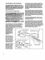
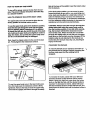
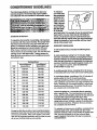
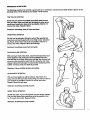
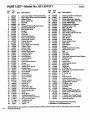
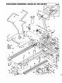
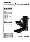
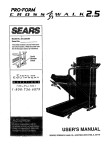
PRO'FORM"
•
IK
CROS;S
D
U
.A
L
""
M
O
T
8E/ARS
I O
N
"'
C
R
O
S
S
"_
T
R
A
I N
E
R
OWNER'S MANUAL
Model No. 831.297231
Serial No.
The serialnumbercan be foundin the
locationshownbelow. Write theserial
numberin the space above.
Serial
"
Number
EOUIPM
[_1
ENT
LIiI::II-1
H
EL.
II/
PLI
[e]
N
I_11,
E!
/-800-72,6-6879
SEARS, ROEBUCK AND CO., HOFFMAN ESTATES, IL 60179
TABLE OF CONTENTS
FULL 90 DAY WARRANTY
...................................................................
2
:: :: : ::::::::: ::::...............................
OPERATIONA_Ib'ADJLI'S'I_ME'I_
" .::.:
.........
i:: ....
:::::::::::::::::::::::::::::::
TROUBLE-SHOOTING
AND MAINTENANCE
...........................................
CONDITIONING GUIDELINES .......................................................
PART LIST .......................................................................
EXPLODED DRAWING .......................
..., ...................................
ORDERING REPLACEMENT PARTS .. ................................................
I
.5.5
9
11
14
15
Back Cover
FULL 90 DAY WARRANTY
For 90 days from the date of purchase, if failure occurs due to defect in material or workmanship in this
SEARS TREADMILL EXERCISER, contact the nearest SEARS Service Center throughout the United
States and SEARS will repair or replace the TREADMILL EXERCISER, free of charge.
This warranty does not apply when the TREADMILL EXERCISER is used commercially or for rental purposes.
This warranty gives you specific legal rights, and you may also have other dghts which vary from state
to state.
SEARS, ROEBUCK AND CO., DEPT. 817WA, HOFFMAN ESTATES, IL 60179
2_
IMPORTANT PRECAUTIONS
BEFORE
YOU
BEGIN
Congratulations for selecting the PROFORM = CROSS
WALK Dual Motion Cross Trainer.
For your benefit, read this manual carefully before
using the CROSS WALK. If you have additional
questions, please call our toll-free HELPLINE at
The CROSS WALK combines the best features of
1-800-736-6879, Monday through Satu_'day, 7 a.m.
until 7 p.m. Central Time (excluding holidays). To help
us assist you, please note the product model number
and serial number before calling. The model number
is 831.297231. The serial number can be found on a
todays most popular home exercise equipment in one
compact unit. The natural motion and versatility of
treadmills have made them the most popular way to
get an effective lower body and cardiovascular workout. Now with the dual motion design of the CROSS
WALK, you can get a complete upper body workout
as well. And the adjustability of the CROSS WALK
allows every user to work at their own level. Whether
you are a beginner or a seasoned athlete, you'll enjoy
the performance and uncompromising quality that
only the CROSS WALK offers.
decal attached to the CROSS WALK (see the drawing
on the front cover for the location of the decal).
Before reading further, please review the drawing
below and farniliadze yourself w_ththe parts that are
labeled.
Upper Body Arms
Knob
_L_..__
C°nsele"_"
_
_
Speed Control
_
_Key/Chp
FRONT
Resistance q
Tabs
Walking Belt
Walking Platform
Motor :
BACK
Foot Rail /
Power Cord /
LEFT SIDE
Rear Leg
Adjustment Belts
4
Note: The rear leg pad may mark some types of linoleum. Mild household cleaning agents will remove any marks.
ASSEMBLY
The CROSS WALK b shipped in the compact stowaway position. Set the CROSS WALK in a cleared area and
remove all packing materials. Make sure that all parts have been removed before you dispose of the pack°
ing materials. Follow the instructionsbelow to convert the CROSS WALK to the operating position. No tools are
required.
1. Raise the Upright (10) to the vertical position. Slide the Lock Knob
Washer (78) onto the Lock Knob (77) and tighten the Lock Knob .
into the UprighL
77
2. Remove the paper backing from the Wrench Clip (65). press the
Wrench Clip onto the Right Roller Bracket (62) in the indicated
location. Press the Allen Wrench (66) into the Wrench Clip.
Make sure that all pads are tightenedsecurely before you use the
treadmill. The use of the remaining parts will be described in other
sections of this manual. Note: To protect the floor or carpet fro m
damage, place a mat under the treadmill.
OPERATION AND ADJUSTMENT
HOW TO INSTALL BATTERIES IN THE CONSOLE
The console requires two "AA" batteries (not included) for the
motivational fitness monitor to operate; alkaline batteries are recommended.
To install batteries, first slide the battery cover open (see the drawing at the right). Remove the battery clip from the console. Find the
maridngs inside the battery clip showingwhich direction the batteries should be turned. Press the batteries into the battery clip.
Replace the battery clip in the console and close the battery cover.
Battery.Cover
•
. _Battery
,ooo.
Clip
THE PERFORMANT
LUBE
TM
WALKING BELT
Your treadmill features a walking belt coated with
PERFORMANT LUBE TM, e hight_erformanca lubricanL
IMPORTANT: Never apply silicone spray or other
substances to the walking belt or the walking platform. They will deteriorate the walking belt and
eause excessive wear.
risk of electric shock. This product is equipped with a
cord having an equipment-grounding
conductor and a
grounding plug. Plug the power cord into a surge
protector, and plug the surge protector Into an
appropriate outlet that is properly installed and
grounded in accordance with all local codes and
ordinances.
This product is for use on a nominal 120-voltcircuit,
and has a grounding plug that looks like the plug Hlustrated in drawing 1 below. A temporary adapter that
looks like the adapter illustrated in drawing 2 may be
used to connect the surge protector to a 2-pole receptacle as shown in drawing 2 if a pmpedy grounded outlet is not available.
HOW TO PLUG IN THE POWER CORD
The temporary adapter should be used only until a
properly grounded outlet (drawing 1) can be installed
by a qualified electrician.
The green-colored rigid ear, tug, or the like extending
from the adapter must be connected to a permanent
ground such as a properly grounded outlet box cover.
Whenever the adapter is used it must be held in place
by a metal screw. Some 2-pole receptacle outlet box..
covers are not grounded. Contact a qualified elec- _
trlclan to determine if the outletbox cover Is
grounded before using an adapter.
Your treadmill, like any other type of sophisticated
electronic equipment, can be seriously damaged by
sudden voltage changes In your home's power.
Voltage surges, spies, and noise interference can
result from weather conditions or from other appliances being turned on
or off. To decrease the
possibnity of your
1
/Grounded
Outlet Box
treadmill being damaged, always use a
surge protector (not
.//Grounding Pin
included) with your
i °
treadmill.
"_munding
Surge protectors are
sold at most hardware
stores and department
stores. Use only a ULlisted surge protector,
rated at 15 amps, with a
14-gauge cord of five "
feet or lees in length.
This product must be
grounded. If it should
malfunction or break
down, grounding provides a path of least
resistance for etectdc
current to reduce the
6
Treadmill Power Cot,
Plug
3rounded Outlet
___1/Grounded
Outlet Box
Adapter
Grounding Pin
ge Protector
_(
Metal Screw
__Grounding
Plug
DIAGRAM O_ THE CONSOLE
Battery Cover-_
_"
[,'!
....
Speed Control Knob
MotJv_JonaJ
_"le,_
Monitor
_
_
• •
m ee
:
Power Switch_-
The CROSS WALK features the innovative ACCUSMART console, designed to help you get the most
from your workouts. Please read the instructions
below before operating the console. Note: If there Is
a thin sheet of clear plastic on the face of the console, remove It before operating the console.
Yourtreadmillfeatures
adjustableincline,controlled
with the inclineknobon the
J rightfootrail. See CHANGING THE INCLINE on page8.
CONTROLLING THE SPEED OF THEWALKING
BELT
The walking belt will be motionless each time the
power is turned on. To start the walking belt, first turn
the speed control knob to the "RESET" position. Next,
turn the knob slowly clockwise until the walking belt
begins to move at slow speed.
Step carefully onto the walking belt and begin exercising. Change the speed of the walking belt as desired
by turning the speed control knob. To stop the walking
belt, turn the knob to the "RESET" position.
THE MOTIVATIONAL
RTNESS MONITOR
The four displays of the motivational fitness monitor
provide instant exercise feedback. The displays are
described below, Note: The displays can be reset by
pressing the ON/CLEAR button.
HOW TO TURN ON THE POWER
Make sure that the power cord is properly plugged in.
(See HOWTO PLUG IN THE POWER CORD on
page 6.)
Next, step onto the foot rails of the CROSS WALK and
hold the upper body arms. (See HOW TO OPERATE
THE UPPER BODY ARMS on page 8.) Locata the clip
attached by a cord to the key. Slide the clip onto your
waistband.
Insert the key into the power switch. The four displays
of the motivational fitness monitor will not appear until
the ON/CLEAR button is pressed or the walking belt
begins to move. (See CONTROLLING THE SPEED
OF THE WALKING BELT on this page.) Note: If batteries were just installed, the four displays will appear
already: ....
............
_
'
• TIME--This display shows the elapsed time. Note:
When the walking belt is stopped, the TIME display
will pause after a few seconds.
• CALORIE--This display shows the approximate
number of nutritional-Calories that you have bumed.
• SPEED--This display shows the speed of the walking belt, in miles per hour.
• DISTANCE--This display shows the total distance
that you have walked or run, in miles.
Note: If the walking belt is stopped for about rive minutes, the four displays will be reset and will darken,
although the power will remain on. The displays will
appear again when the ON/CLEAR button _ pressed,
or the walking belt Is restarted. ......
7
tabs at the base of the updghL Insert the hairpin cotter
into the lock pin.
HOW TO TURN OFF THE POWER
To turn off the power, remove the key from the console. The power indicator will darken. Store the key
in a secure location.
HOW TO OPERATE THE UPPER BODY ARMS
The upper body arms can be used in either the stationary position or the dual motion position.
To use the upper body arms in the stationary position,
Insed the lock pin through the arms and the upright
(see the drawing below). Important: If It is difficult
to Insert the lock pin, do not hit the end of the lock
pin; twist each upper body arm slightly In order to
align the holes. Do not twist the upper body arms
too far or the treadmill may be damaged.
Next, Insert the hairpin cotter into the end of the lock
pin. Firmly tighten the resistance control.
In the dual motion position,you can move the arms
forward and back as you walk or run, exercising your
arms, back and shoulders for a total body workouL To
tailor the Intensity of your exercise, the resistance of
the arms can be changed. To increase the resistance,
turn the resistance control clockwise; to decrease the
resistance, turn the control counterclockwise.
CAUTION: Nways Insert the lock pin through the
safety tabs when using the upper body arms in
the dual motion position. If you fall while exercisIng, the lock pin will limit the downward movement of the arms. When the lock pin Is Inserted
through the safety tabs, do not lean on the upper
body arms or the lock pin may be damaged. If the
hairpin cotter is not attached to the lock pin as
Instructed, the lock pin may slip out, resulting in
Injury to the user.
CHANGING THE INCUNE
Hairpin
Lock Pin
Safety
To vary the intensity of your exercise, the incline of
the treadmill can be changed. Before changing the
Incline, make sure that the walking belt is
stopped.
\
Control
Knob
Lock
Cotter
To use the upper body arms in the dual motion position, first make sure the resistance control is firmly
tightened. Remove the lock pin from the upper body
arms and the updght, and insert it through the safety
To increase the incline, stand with your left foot
towards the back of the left foot rail as shown
below. Using your right foot, press down the incline
knob on the dght foot rail, until the desired incline is
reached. To decrease the incline, stand with your
left foot towards the front of the left foot rail, and
press down the incline knob until the desired incline is
reached.
TROUBLE-SHOOTING AND MAINTENANCE
Most treadmill problems can be solved by following the simple steps below. Rnd the symptom that
applies, and follow the steps listed, ff further assistance Is needed, call our toll-frae HOTLINE at 1-800736-6879, Monday through Saturday, 7 a.m, until 7 p.m. Central Time (excluding holidays).
1. SYMPTOM: THE POWER DOES NOT TURN ON
a. Make sure that the power cord Is plugged into a surge protector, and that the surge protector Is plugged into
a proparly grounded ouUeL (See HOW TO PLUG IN THE POWER CORD on page 6.) Use only a UL-IIsted
surge protector, rated at 15 amps, with a 14-gauge cord of five feet or less in length.
b. Make sure that the key Is inserted fully into the console. Turn the speed c0ntrol knob to the "reset" position.
(See HOW TO TURN ON THE POWER on l_age 7.)
c. Check the circuit breaker located on the front of the frame.
The circuit breaker Is designed to protect the electrical system. If the circuit breaker has tripped, the switch will protrude
as shown. To reset the circuit breaker, allow the CROSS
WALK to cool for five minutes, and then push the switch back
in.
Tdpped
Reset
2. SYMPTOM: THE POWER TURNS OFF DURING USE
a. Make sure that the power cord Is plugged in.
b. Check the circuit breaker located on the front of the frame. If the circuit breaker has tripped, the switch will
protrude. (See the drawing above.) To reset the circuit breaker, allow the CROSS WALK to cool for five minutes, and then push the switch back in.
c. Remove the key from the console. Reinsert the key fully into the console. Turn the speed control knob to the
"reset" position.
3. SYMPTOM: THE MOTIVATIONAL
FITNESS MONITOR DOES NOT FUNCTION PROPERLY
a. Check the battedes in the console. (See HOW TO INSTALL BATTERIES IN THE CONSOLE on page 5.)
Most problems are the result of drained battedes.
• 4. SYMPTOM: THE CROSS WALK DOES NOT INCLINE
a. Stand with your left foot towards the back of the foot rail while increasing the incline. Stand with your left foot
towards the front of the foot rail while decreasing the incline. You may need to raise and lower the treadmill
several times to break in the incline shock. (See CHANGING THE INCUNE on page 8.)
5. SYMPTOM: THE WALKING BELT SLOWS WHEN WALKED ON
a. Use only a UL-listed surge protector, rated at 15 amps, with a 14-gauge curd of five feet or less in length.
b. If the walking belt Is overtightoned, performance may be reduced
and the walking belt permanently damaged. UNPLUG THE
POWER CORD. Using the included allen wrench, tum both rear
roller adjustment bolts counterclockwise 114of a turn. When the
tension of the walking belt is correct, you should be able to lift
each side of the walking belt 2 to 3 inches; the center of the walking belt should just touch the surface of the walking platform. Be
sure to keep the walking belt cantered. Run the treadmill for a few
minutes. Repeat until the tension of the walking belt is correcL
_"
c. If the walking belt still slows when walked on, please call our toll-free HOTLINE.
Rear Roller
6. SYMPTOM: THE WALKING
ao
BELT IS OFF-CENTER OR SLIPS
If the walking belt has shifted to the left, first remove the key and
UNPLUG THE POWER CORD. Using the allen wrench, turn the
left rear roller adjustment bolt clockwise, and the right bolt counterolockwisa, 1/4 of a turn each. Be careful not to overtighten the
walking belt. Plug in the power cord, insert the key and run the
treadmill for a few minutes. Repeat until the belt is centered.
b. If the walking belt has shifted to the right, first remove the kay
• and UNPLUG THE POWER CORD. Using the allen wrench, turn
the left rear roller adjustment bolt counterclockwise, and the dght
bolt clockwise, 1/4 of a turn each. Be careful not to ove_ghten
the Walking bell Plug in the power cord, insert the key and run
the treadmill for a few minutes. Repeat until the belt is centered.
c. If the walking belt slips when walked on, first remove the key and
UNPLUG THE POWER CORD. Using the allen wrench, turn
both rear roller adjustment bolts clockwise, 1/4 of a turn. When
the walking belt is correctly tightened, you should be able to lift
each side of the walking belt 2-3 inches off the walking platform.
The canter of the walking belt should just touch the walking platform. Be careful to keep the walking belt centered. Plug in the
power cord, insert the key and run the treadmill for a few minutes. Repeat until the walking belt is properly tightened.
7. SYMPTOM: IT IS DIFRCULT
TO INSERT OR REMOVE THE LOCK PIN
a. It may be necessary to twist each upper body arm slightly in order to align the holes that the lock pin goes
through. Do not twist the upper body arms too far or you may damage the treadmill.
STORAGE
Before converting the CROSS WALK to the stowaway position,
turn the Resistance Control (15) counterclockwise until the
Control turns freely.
Unplug the power
Washer (78) from
Right Upper Body
Knob and Washer
10
cord. Remove the Lock Knob (77) and Lock Knob
the Updght (10). Lay the Updght and the Left and
Arms (1, 2) on the walking belt. Keep the Lock
in a secure location.
CONDITIONING GUIDELINES
The following guidelines will help you to plan your
exercise program. Remember that proper nutrition
and adequate rest are essential for successful results.
_rogram,
To measure
your heart rate,
stop exercising
and place two
fingers on your
wrist es shown.
Take a six-second heartbeat
coun_ and multiply theresuft
by10tofind
EXERCISE INTENSITY
To maximize the benefits of exercising, it is important
to exercise with the proper intensity. The proper Intensity level can be found by using your heart rate as a
guide. For effective aerobic exercise, your heart rate
should be maintained at a level between 70% and
85% of your maximum heart rate as you exercise.
This is known as your training zone. You can find your
training zone in the table below. Training zones are
listed for both unconditioned and conditioned persons
according to age.
Tralning Zone
Age
Unconditioned
(Beats/Min.)
Conditioned
(Beats/MIn.)
20
138-167
133-162
25
136-166
132-160
30
135-164
130-158
35
134-162
129-156
40
132-161
127-155
45
131-159
125-153
50
129-156
124-150
55
127-155
122-149
60
125-153
121-147
65
125-151
119-145
70
123-150
118-144
75
122-147
117-142
80
120-146
115-140
85
118-144
114-139
During the first few months of your exercise program,
keep your heart rate near the low end of your training
zone as you exercise. After a few months, your heart
rate can be increased gradually until it is near the middle of your training zone as you exercise.
your heart rate. For example, if your six-second headbeat count is 14, your heart rate is 140 beats per
minute. (A six-second count is used because your
heart rats will drop rapidly when you stop exercising.)
Adjust the Intensity of your exeri:lse until your head
rate is at the proper level.
WORKOUT GUIDEUNES
A well-roundadworkout includesthe followingthree
phases."
A warm-up phase, lasting 5 to 10 minutes. Begin
with slow, controlled stretches, and progress to more
rhythmic stretches to increase the body temperature,
heart rate and circulation in preparation for strenuous
exercise. Stretching also guards against muscle, tendon and ligament sprains. (See SUGGESTED
STRETCHES on page 13.)
A cardiovascular phase, including 20 to 30 minutes
of exercising with your heart rate in your training zone.
A cool-down phase, consisting of 5 to 10 minutes of
activity similar to that of the warm-up phase.
Thorough stretching offsets muscle contractions and
other problems caused when you stop exemising suddenly. Stretching for increased flexibility is often most
effective during this phase. This phase should leave
you .relaxed and comfortably tired.
Instead of waiting for a convenient time to exercise,
plan a specific time. The morning hours work well for
many, and the self-discipline required to dse early and
exercise often carries through the day to help
increase productivity in other areas. For some, exerrising before dinner initiates a period of winding down
from the day's activities. Whatever time you choose,
be consistent and stick with iL
To maintain or improve your condition, complete three
workouts each week, with at least one day of rest
between workouts. After a few months of regular exercise, you may complete up to five workouts each
week, if desired. Remember, the key to success is ......
CONSISTENCY.
t1
WORKOUT
AI"I'IRE
•
Exemise dothing should be comfortable and allow
unrestdcted movemenL Do not wear rubhedzed or
plastic clothing that can interfere with the evaporation
of sweat from your skin. Always wear athletic shoes
that are flexible and provide good protection and sup
port.
ADDITIONAL
Keep yourself moving throughout the day. Use the
stairs instead of the elevator. Park a half mile away
from work or get off the bus a couple of blocks
before your stop and walk the remaining distance.
•
12
Stop smoking; smoking nearly doubles the risk of
coronary heart d.iseese. (Framington Heart Study)
Reduce or eliminate alcohol consumption. Alcohol
Is a major cause of liver problems and other health
disorders. (Office of Disease Prevention and Health
Promotion)
SUGGESTIONS
Creating a more active lifestyle, In addition to establishing a regular exercise program, will help you to achieve
your fitness goals. It's easy to Improve your lifestyle by
making a few changes in your daily routine:
Increase midday productivity, creativity and energy
by replacing a heavy lunch with a light meal. Spend
the extra time in physical activity such as walking.
Substitute manually-operetod devices for automatic
equipment such as lawn-care machinery, power
tools and snow removers.
•
Reduce your Intake of faL Less than 30% of the
calodes you consume each day should coma from
fat. Excessive fat consumption has been linked to
numerous causes of death, including heart disease
and cancer.
Know and keep a record of your cholesterol level,
blood pressure and other health information. Keep
your blood pressure below 140/90; keeping it below
125/85 is preferable.
SUGGESTED STRETCHES
The following stretches can provide a good warm-up or cool-down. Con'ect form for each stretch is shown in the
drawings below. Move slowly as you stretch--never bounce.
TOE TOUCH STRETCH
Stand with your knees bent siightJy and slowly bend forward
from your hips. Allow your back and shouldem to relax as you
reach down toward your toes as far es poesible. Hold for 15
counts, then relax. Repeat 3 times.
Stretches: Hamstrings, back of knees and back.
HAMSTRING STRETCH
Sit with one leg extended. Bdng the sole of the opposite foot
toward you and rest it against the inner thigh of your extended
leg. Reach toward your toes as far as possible. Hold for 15
counts, then relax. Repeat 3 times for both legs.
Stretches: Hamstrings, lower back and gro'm.
CALF/ACHILLES STRETCH
With one leg in front of the other, reach forward and place your
hands against a wall. Keep your back leg straight and your
back foot fiat on the floor. Bend your front leg, lean forward and
move your hips toward the wail. Hold for 15 counts, then relax.
Repeat 3 times for both legs. To cause further stretching of the
achilles tendons, bend your back leg as well.
Stretches: Calves, achilles tendons and anldes.
QUADRICEPS STRETCH
With one hand against a wall for balance, reach back and
grasp one foot with your other hand. Bdng your heel as close to
your buttocks as possible. Hold for 15 counts, then relax.
Repeat 3 times for both legs.
Stretches: Quaddceps and hip muscles.
INNER THIGH STRETCH
Sit with the soles of your feet together and your knees outward.
Pull your feet toward your groin area as far as possible. Hold
for 15 counts, then relax. Repeat 3 times.
Stretches: Quadricops and hip muscles.
PART LIST--Model
14
Key
No.
Part
No.
1
2
3
4
5
6
7°
8
9
10
11
12
13
14
15
16
17
-16
19
20
21
22
23
24
25
26
27
28
29
30
31
82
33
34
35
36
37
38
39
40
41
42
43
44
45
46
47
48
49
50
51
52
53
125260
125261
015044
012108
114575
108404
127726
110000
126242
121266
121544
109786
124009
125263
116693
110193
014087
122634
112286
124301
126155
126243
122812
013547
113106
109382
124695
014157
031238
124669
013162
125790
125264
052014
117806
118202
115672
054016
059019
111436
106616
106334
107508
122632
120867
124100
113814
112825
125265
114261
121446
121109
NSP
Qty.
1
1
1
1
1
10
1
1
1
1
1
1
2
1
1
2
2
2
2
1
2
1
1
1
5
1
1
1
1
1
8
1
1
2
2
1
1
1
1
1
1
1
1
1
1
1
2
1
1
1
2
1
1 't
No. 831.297231
Descdptlon
Left Upper Body Arm/Foam/Housing
Right Upper Body Arm/Foam/Housing
Hairpin Cotter
Motor Swivel Nut
Key/Clip
Screw
Consola/Pot/Y,.noWBattery Cover
Speed Control Knob
Foot Incline Knob
Upright
Look Pin
Controller
Inclina Leg Washer
Motor Hood w/Decal
Resistance Control
Friction Bracket
Flat Washer
Upper Body Arm Housing
Friction Plata
incline Cable
Shook Spacer
Incline Knob Sleeve
Tension Washer.
Tension Bolt
Hood Bracket
Circuit Breaker
Grommet
Reed Switch Washer
Choke
Power Cord
Safety Cover Screw
Safety cover
Left Foot Rail w/Fastener
Front Wheel
WheelBolt
Shock Release
Shock Bracket
E-Clip
Shook Cushion
Incline Shook
Shook Pin
Cotter Pin
Motor Pivot Bolt
Motor Mount Bracket
Motor Tension Nut
Motor
MotorBolt
Pulley/Flywheel/Fan
Right Foot Rail w/Fastener
Motor Ground Wire
Incline Leg Bolt
Incline Leg
Frame-
Key
No.
54
55
56
57
58
59
60
61
62
63
54
65
66
67
68
69
70
71
72
73
74
75
76
77
78
79
80
81
82
83
84
85
86
87
88
89
90
91
92
93
94
95
96
97
98*
#
#
#
#
#
Part
No.
125266
100691
014127
112609
126110
124098
121267
110407
125268
013300
105444
016028
045010:1
110245
014066
121268
124318
125267
100498
115569
121272
118016
016055
017088
014156
121269
109515
112023
101049
105477
111869
016029
120630
012146
016057
012056
116435
124302
014117
124615
113203
127727
124703
110402
124151
116131
107109
124762
107771
125824
Qty.
Description
1 ' Walking Platform w/Fastener
6
Platform Screw,
3
Roller Adjustment Washer
1
Front Roller Adjustment Bolt
1
Front Roller/Pulley
1
Walking Beftw/Fastener
1
Upright Cover, Long
1
RearLegPad
1
Right Endcap
3
Reed Switch Screw
2
Rear Roller Adjustment Bolt
1
WrenchClip
AllenWranch
1
Rear Roller
1
CablaWasher
1
Short Upright Cover
2
Belt Guide
1
Left Endcap
1
Magnet
1
Reed Switch/Sensor Wire
1
Mechanism Cover
1
Belt
2
Wire Clip
1
LockKnob
2
Look Knob WashedControl Washer
1
Friction Cover
1
Pivot Bolt
2
Foam Grip
5
Hood Bracket Screw
2
Motor Nut
1
Cage Nut
2
4"Cabla'ria
10 Belt Guide Screw/Bracket Screw
2
Cable Nut
3
8"CableTle
4
Nut
1
Incline Lever
1
Incline Knob Bracket
1
MotorTension StarWasher
1
Upright Wire Harness
1
6" Cable Loom
1
Potentiometer
1
Pot Wire
1
Battery Cover
1
Motor/Pulley/Flywheel/Fan
1
Power Board WireHamess
12 Fastener
1
4" Black Wire, Male/Female
1
8" White Wire, Male/Female
1
Owner's Manual
* Includes all the parts shown in the box.
# tnd'_catesa non-Illustrated part. "
"
Specifications are subject to change without notice. See the back cover for information about ordering
replacement parts..
EXPLODED DRAWING--Model No. 831.297231
R0296A
81
.-
81
7*
11
86
/
78
17
14
°
.-
58
55
33
2O
71
55
/J
52
38
86
66
65
49
47
i
56
.-'
"62
53
22
21
61 .o"
42
i
_3
5O
44
i15 .
SE /A/RS
The model number and serial number of your PROFORM" CROSS
WALK Dual Motion Cross Trainer are listed on a decal attached to
the frame. See the front cover of this manual to find the location of
the decal.
Model No, 831.297231
QUESTIONS?
All replacement parts are available for immediate purchase or
special order when you visit your nearest SEARS Service Center.
To request service or to order parts by telephone, call the toll-free
numbers listed at the left.
If you find that:
• you need help assembling or
operating the CROSS WALK
• a part is missing
• or you need to schedule repair
service
call our toll-free HELPLINE
When requesting help or service, or ordering parts, please be prepared to provide the following information:
• The NAME OF THE PRoDUcT
Dual Motion Cross Trainer)
(PROFORIvP CROSS WALK
1-800-736-6879
• The M(3DEL NUMBER OFTHE PRODUCT (831.297231)
Monday-Saturday, 7 am-7 pm
Central Time (excluding holidays)
• The PART NUMBER OF THE PART (see page 14 of this manual)
• The DESCRIPTION
OF THE PART (see page 14 of this manual)_"=
SEARS, ROEBUCK AND CO., HOFFMAN ESTATES, IL 60179 USA
REPLACEMENT
PARTS
If parts become wornand need to
be replaced, call the following
toll-free number
1-800-FON-PART
(1-800-366-7278)
Part No. 125824 F0033AC R0296A
Printed in USA © 1996 Sears, Roebud¢ and Co: