1
FOR YOUR SAFETY
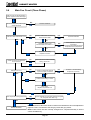
If you smell gas:
1. Open windows.
2. DO NOT try to light any appliance.
3. DO NOT use electrical switches.
4. DO NOT use any telephone in
your building.
5. Leave the building.
6. Immediately call your local gas
supplier after leaving the building.
Follow the gas supplier’s
instructions.
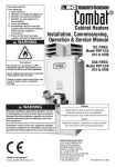
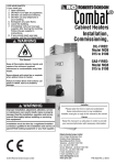
WARNING
Warm Air Cabinet
Heaters
Installation,
Commissioning,
Service & User
Instructions
Fire Hazard
Do not store or use petrol or other
flammable vapours and liquids in the
vicinity of this or any other appliance.
Failure to follow these instructions
can result in death, injury or property
damage.
OIL FIRED: POP--ECA
Models 15 to 100
GAS FIRED: PGP--ECA
Models 15 to 100
WARNING
Improper installation, adjustment, alteration,
service or maintenance can result in death, injury
or property damage. Read the Installation,
operation and service manuals thoroughly before
installing or servicing this equipment
Installation must be done by a contractor qualified
in the installation and service of gas/oil fired
heating equipment (whichever is applicable).
Installer
Please take time to read and understand these
instructions prior to any installation. Installer must
give a copyof this manual to the user/owner.
Owner/User
Keep this manual in a safe place close to the heater
to provide your serviceman with information should it
become necessary.
Roberts-Gordon Europe Ltd.
Oxford Street
Bilston, West Midlands WV14 7EG UK
Telephone: +44 (0)1902 494425
Fax: +44 (0)1902 403200
email: [email protected]
www.combat.co.uk
www.rg-inc.com
© Copyright 2002 Roberts-Gordon
X523G 08/04
CABINET HEATER
Contents
The parts of this manual are numbered by section, clause and sub clause. Hence: 1.2.3 refers to Section 1, clause 2,
sub clause 3. Figure numbers also follow this notation hence: Fig 2.3 is Section 2, fig.3.
SECTION
PAGE
1.
General Specification
3
2.
Technical Data
7
3.
Installation Requirements
29
4.
Installation of the Air Heater
33
5.
Commissioning of the Air Heater
39
6.
Wiring Diagrams
46
7.
Servicing Instructions
56
8.
Removal and Replacement of Parts
58
9.
Fault Finding Charts
60
10.
User Instructions
67
11.
Conversion information
72
12.
Parts List
73
13.
Commissioning Data Sheet
74
THIS MANUAL RELATES TO THE AIR HEATERS WHICH ARE MANUFACTURED FOR USE WITH:OIL FIRED HEATERS:
Class D fuel oil to BS 2869
Which is similar to
Gas oil with a maximum viscosity at 20° C of 1.5° E
GAS FIRED HEATERS
Natural gas G20
L.P.G Propane (G31)
THESE INSTRUCTIONS ARE TO BE LEFT WITH THE USER OR NEAR THE HEATER
Note: Every effort is made to ensure that the information within this manual is accurate.
However, Robert-Gordon reserves the right to alter specifications without prior notice.
Roberts-Gordon shall not be liable to rectify any defects or damage caused by any modifications made or attempted to
be made to the heating units by the customer, his servants, agents or employees.
Page 3
CABINET HEATER
Section 1.
1.1
General Specification
General Information - Standard Models
COMBAT® cabinet warm air heaters are self contained units fitted with a packaged burner and are supplied ready for
installation on site to be used with external controls.
The burner controls which form part of the packaged burner are designed for safe operation between
-20°C to 60°C. However the heater should not be operated in ambient temperatures above 32°C .At Ambient temperatures
above 29°C some models may require the maximum heat input to be reduced, seek advice from Roberts-Gordon UK
Ltd. under these circumstances
The standard PGP---ECA or POP ---ECA heater is the ‘free standing’ model.
Models are available with various options are:
PGP--ECA-S
models for use in the horizontal (suspended) mode
gas fired ranges for Ecoflam high /low burners
gas fired ranges for Ecoflam fully modulating burners
weatherproof models for external siting
PGP---ECA-S
models for use in the horizontal (suspended) mode
oil fired ranges are also available with Ecoflam High /Low burners
weatherproof models for external siting
COMBAT® cabinet heaters are available with heat outputs ranging from 47.4kW to 293kW.
All heaters are fitted with fully automatic 'packaged' forced draught oil fired or gas fired burners manufactured for RobertsGordon UK Ltd.
The heater cabinets are manufactured in Zintec coated mild steel which is finished with a stove cured powder coat
paint.
The combustion chambers are of high grade stainless steel construction. The heat exchangers are mild steel tubular
all welded construction.
Centrifugal fan(s) located in the base of the heater cabinet provide heated recirculation air, which is distributed from the
top of the heater through the fully adjustable louvred outlet heads.
The fan(s) are either direct drive or belt driven dependent upon model:
Models 015 - 050 inclusive - Direct Drive (except High Flow)
Models 060 - 0100 inclusive - Belt Drive
The required electrical supply is: 230 volt 50Hz single phase on models 15 to 30 and 400 volt 50Hz three phase and
neutral on models 40 to 100 (Models PGP and POP 040 and 050 are also available as single phase belt drive to special
order). All High Flow models require a 400V, 50Hz, three phase and Neutral electrical supply.
ON/OFF control, temperature control, time control, and frost protection are available as a remote control which needs
to be site wired to afford proper operation of the heater. Alternatively, any remote energy controls may be used which
must be installed in accordance with Section 4.3.
Each heater must be fitted with its own natural draught flue in accordance with local regulations and the instructions in
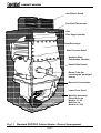
this booklet. Fig. 1.1 shows the basic parts of the heater.
Page 4
CABINET HEATER
Air Diffuser Heads
Fan/Limit Thermostat
Flue
Flue Spigot (female)
Heat Exchanger
Rear Pressure Relief
Stainless Steel
Combustion Chamber
Double Skin Panels
Burner Tube (for
mounting the 'packaged'
burner)
Electrical Connections
Lower Front Panel
Main Fan Assembly
(Direct Drive on
Models 15 - 50,
Belt Dive on
Models 60 -100)
Fig 1.1 Standard PGP/POP Cabinet Heater - General Arrangement
Page 5
CABINET HEATER
1.2
Heater Operation (On/Off)
Once the heater has initially been switched on using the remote controls, the operation of the heater becomes automatic
under the control of the remote time/temperature controls (as fitted on site) and the safety devices.
When the external controls call for heat, the control box of the fully automatic burner checks that all systems are in a
safe and ready position, and then initiates a start sequence. It then constantly monitors safe operation of the burner
(see Section 2.2 & 2.3 for details).
When the heat exchanger has been sufficiently heated, the built in fan thermostat turns on the main fan(s) and warm
air is distributed from the top of the heater.
Note: On horizontally mounted heaters, High Flow heaters, heaters fitted with high/low or modulating burners and
some fully ducted heaters, the fan will come on during the burner firing cycle and not wait for the temperature rise. This
is to ensure that there is always a proper operation of the heater under all possible conditions.
At the close down of the external controls, the burner shuts off and the main fan(s) continue to run until the fan
thermostat detects a drop in leaving air temperature, sufficient to turn it off. The heater is then at rest until the beginning
of the next cycle.
If for any reason the main fan should fail or the air flow through the heater is reduced, then the built in limit thermostat
will cause the burner to go to safety shut down ‘lockout’. This condition will remain until the fault is corrected and the
manual ‘red’ reset button is operated at the limit thermostat.
1.2.1
Heater Operation (High/Low)
For burners which are capable of High/Low operation, a two stage thermostat will be required to be installed on site to
alow the burner to operate On/Off and High/Low dependant upon conditions (see 4.3.1.1 for details)
1.2.2
Heater Operation (Fully Modulating)
For gas burners only which are capable of Fully Modulating operation the burner comes complete with a temperature
control system. The sensor of this system needs to be installed on site (see 4.3.1.2) to allow the burner to vary the heat
input to maintain a constant control temperature.
WARNING
The main electrical isolator should only be used in an emergency and for servicing.
It should never be used for closing down the burner, as this switches off the main fan prematurely
and may damage the heat exchanger, invalidating the warranty and causing a potential fire hazard.
Page 6
CABINET HEATER
Section 2.
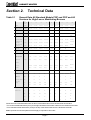
Table 2.1
Technical Data
General Data All Standard Models PGP and POP and All
Versions for High/Low or Modulating Burners
Model
P G P / POP
- - ECA
15
20
30
40
50
60
70
80
100
A W i d th
mm (ins)
724 (28½)
724 (28½)
724 (28½)
857 (33¾)
857 (33¾)
1016 (40)
1016 (40)
1016 (40)
1016 (40)
B D e p th - C a b .Only
mm (ins)
857 (33¾)
857 (33¾)
857 (33¾)
857 (33¾)
1016 (40)
1676 (66)
1676 (66)
1676 (66)
1994 (78½)
C Height - Cab.Only
mm (ins)
1740 (68½)
1740 (68½)
1740 (68½)
1930 (76)
1930 (76)
1930 (76)
1930 (76)
1930 (76)
1930 (76)
D D e p th Overall Oil
mm (ins)
1220 (48)
1220 (48)
1220 (48)
1254 (49½)
1413 (55¾)
2251 (88¾)
2251 (88¾)
2251 (88¾)
2569
(1 0 1 ¼ )
D D e p th Overall Gas
mm (ins)
1306 (51½)
1306 (51½)
1306 (51½)
1348 (53)
1507 (59½)
2388 (94)
2388 (94)
2388 (94)
2706
(1 0 6 ½ )
E H e i g h t Inc l . H e a d s
mm (ins)
1988 (78¼)
1988 (78¼)
2058 (81)
2235 (88)
2235 (88)
2235 (88)
2235 (88)
2235 (88)
F L / R H a n d A i r Inlet
Spigot Depth
mm (ins)
781 (30¾)
781 (30¾)
781 (30¾)
781 (30¾)
940 (37)
1600 (63)
1600 (63)
1600 (63)
G L / R H a n d A i r Inle t
Spigot Height
mm (ins)
457 (18)
457 (18)
457 (18)
559 (22)
559 (22)
559 (22)
559 (22)
559 (22)
H R e a r A i r Inle t
Spigot Depth
mm (ins)
648 (25½)
648 (25½)
648 (25½)
781 (30¾)
781 (30¾)
N/A
N/A
N/A
J R e a r A i r Inlet Spigot
Height
mm (ins)
361 (14)
361 (14)
361 (14)
446 (17¾)
446 (17¾)
N/A
N/A
N/A
Weight
kgs (lbs)
200 (441)
200 (441)
200 (441)
245 (540)
270 (595)
440 (970)
440 (970)
440 (970)
Number and size of
air discharge heads
mm
2 x 229
2 x 229
2 x 356
2 x 356
2 x 356
6 x 356
6 x 356
6 x 356
F lue D i a m e te r
mm (ins)
178 (7)
178 (7)
178 (7)
178 (7)
178 (7)
229 (9)
229 (9)
229 (9)
M o tor Type
D ir. D rive
D i r. D rive
D ir. D rive
D ir. D rive
D i r. D rive
B e lt D rive
B e lt D rive
B e lt D rive
M o tor Size
0 .75 (1)
0.75 (1)
0.75 (1)
2 .2 (3)
2.2 (3)
1 .5 ( 2 )
2.2 (3)
2 .2 (3)
2235 (88)
1918 (75½)
559 (22)
N/A
N/A
530 (1168)
6 x 356
229 (9)
M A IN F A N
M o tor Pulley
k W (hp)
n/a
n/a
n/a
n/a
n/a
2A x 80mm
2A x 95mm
2A x 95mm
Fan Pulley
PCD
n/a
n/a
n/a
n/a
n/a
2 A x1 8 0 m m
2 A x1 8 0 m m
2Ax180mm
Main Fan Start
C urrent
amps
24
24
28
21
21
10.2
30
30
Main Fan Run Current
amps
5 .3
5.3
6.3
6 .2
6.2
3.5
5.1
5 .1
Airflow (Free
B lo w i n g )
M ³/hr
3398
3398
5097
6796
8495
11044
12443
12443
ft/hr
2000
2000
3000
4000
-5000
6500
7500
7500
kW
2 .1
2.1
2.1
5 .4
5.4
4.4
5.5
5 .5
V o lts
230
230
230
400
400
400
400
400
Hertz
50
50
50
50
50
50
50
50
P hase
1
1
1
3N
3N
3N
3N
3N
B e lt D rive
4 (5 .4)
2A x106mm
2A x
180mm
35
9.6
17330
10200
A C E lectrical Supply
To tal E le c . L o a d
6.6
400
50
3N
Dimensions for Horizontal heaters are as above, with heaters lain on their left hand side as standard.
* For vertical models add 54mm (2 ins) to the right hand side of the heater cabinet for the fan/limit thermostat.
* For horizontal models add 54mm (2 ins) to the top of the heater cabinet for the fan/limit thermostat.
Note: A permanent uninterrupted electrical supply is required for all models
Page 7
CABINET HEATER
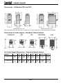
Dimensions - All Models PGP and POP
Cabinet Sizes 015 - 050
Cabinet Sizes 060 - 0100
Note: Horizontal heater dimensions are as vertical units, but with heaters lain on their left hand side as standard.
Dimensions of outlet spigots - Standard Cabinet Heaters
015/020/030
040
050
060/070/080
0100
Air Outlet Spigot Dimensions - Standard Cabinet Heaters
MODEL
015
020
030
040
050
060/070/080
0100
K Spigot Width
mm
(ins)
648
(25½)
648
(25½)
648
(25½)
781
(30¾)
781
(30¾)
940
(37)
940
(37)
L Spigot Depth
mm
(ins)
476
(18½)
476
(18½)
476
(18½)
476
(18½)
610
(24)
1238
(48¾)
1524
(60)
Page 8
CABINET HEATER
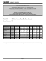
DATA TABLES - IMPORTANT NOTE
When reading the Data Tables 2.3 to 2.9 on the following pages,
ensure that the correct table for the burner and gas valve installed is being used.
The Data Tables are listed under a burner reference letter which can be found
on the heater data plate.
Refer also to the Burner Manufacturer's Instructions
and the specific instructions supplement where applicable.
The burner settings shown in the instructions should be used for burner settings.
Table 2.3
Oil Fired Burner Data (Ecoflam Burner)
Burner Reference "G"
Model
He a t I n p u t ( g r o s s )
Nom inal He a t o u t p u t
POP 030
POP 040
POP 050
POP 060
POP 070
POP 080
Kw
55.5
73.3
93.2
129.9
162
208
242
275.2
348.5
Btu/hr x 1000
189.4
250.1
318.0
443.2
552.7
709.7
825.7
939.0
1189.082
Kw
47.4
61.2
78.4
110.2
134.5
177.7
205.3
230.4
293.4
161.8
208.9
267.4
375.9
458.8
606.5
700.3
786.2
1001.0
Minor 8
Minor 8
Minor 12
Minor 20
Minor 20
Minor 30
Minor 30
Minor 30
Major 30
1.00
1.50
2.25
3.00
3.50
4.00
5.00
5.50
7.00
60S
60S
60S
60S
60S
60S
60S
60S
60S
Us gall/hr
A n g le & T y p e
M ake
He a d s e t t i n g
A ir s e t t ing
POP 0100
Btu/hr
Ecoflam B u r n e r t y p e
Nozzle Size
POP 015 POP 020
mm
Danf o s s Danf o s s
8
0
Danf o s s
Danf o s s
Danf o s s
Danf o s s
8
8
8
8
(Fully back) (Fully back) (Fully back) (Fully back)
Danf o s s
8
(Fully back)
Danf o s s
Danf o s s
8
(Fully
(Fully back) Forw ard)
Number
4.2
8.5
6.5
3
4
3.7
4.5
6.2
4
Bar
14.0
9.8
5.8
7.7
8.9
10.7
9.2
8.1
10.2
pressure
PSI
203
143
84
111
129
155
134
118
148
Fue l
L/hr
5.2
6.8
8.7
12.1
15.1
19.4
22.5
25.6
32.4
Burner fuel
cons u m p t i o n
imp gall.hr
1.1
1.5
1.9
2.7
3.3
4.3
5.0
5.6
7.1
M ax. oil pr e s s u r e
Bar
0.21
0.21
0.21
0.21
0.21
0.21
0.21
0.21
0.21
t o p u m p inle t
PSI
3
3
3
3
3
3
3
3
3
Note: High Flow Heaters are fitted with burners to the same specification as the POP 30, 40 and 50 models for oil firing.
Page 9
CABINET HEATER
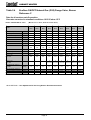
Table 2.4
Ecoflam ON/OFF Natural Gas (G20) Dungs Valve, Burner
Reference C
Data for all versions on/off operation
Gas rates corrected to standard conditions 1013.25 mbar 15°C
INLET PRESSURE 20 m b a r
MODEL
(Minim u m 17 m b a r, M a x i m u m 2 5 m b a r )
PGP 15
EC A
PGP 20
EC A
PGP 30
EC A
PGP 40
EC A
PGP 50
EC A
PGP 60
EC A
PGP 70
EC A
PGP 80
EC A
PGP 100
EC A
Gross heat input
(kW)
55.5
73.3
93.2
129.9
162.0
208.0
242.0
275.2
348.5
Net heat Input
(kW)
50.0
66.0
84.0
117.0
146.0
187.4
218.0
248.0
314.0
Approx heat output
(kW)
47.4
61.2
78.4
110.2
134.5
177.7
205.3
230.4
293.4
Start Gas Orif ice
(mm dia.)
5.0
6.0
7.0
7.0
7.0
7.0
Max Gas Rate
(Sm3 /hr)
5.3
7.0
8.9
12.4
15.4
19.8
23.1
26.2
33.2
Main Burner Gas Pressure
(mbar)
4.0
2.7
4.2
4.8
7.7
5.2
7.1
12.7
10.0
Start Gas Pressure
(mbar)
BURNER TYPE
Burner Head
Head Setting
(mm)
N/A
N/A
N/A
1.8
2.8
0.9
1.1
1.7
3.4
A Z UR
BLU
BLU
BLU
BLU
BLU
BLU
BLU
BLU
60
120
120
170
250R
250
250
250S
350
s
s
s
s
s
s
s
s
s
0
10
11
15
14
24
24
24
21
A ir Setting
2.6
4.2
6
2.2
3.5
2.9
3.6
1.4
1.6
V a lve Type
MBDLE
MBDLE
MBDLE
MBDLE
MBDLE
MBDLE
MBDLE
MBDLE
MBDLE
405
405
405
407
410
410
410
410
412
S
S
S
S
S
S
Main Gas
V a lve Type
Start Gas
0 832 051 0 832 051 0 832 051 0 832 051 0 832 051 0 832 051
A IR PRESSURE SWITCH
SETTING
(mbar)
1.5
1.5
4.5
4.0
6.5
5.0
6.5
7.5
7.0
(mbar)
-0.05
-0.05
-0.09
-0.30
-0.05
-0.25
-0.17
0.10
0.45
3/4"
3/4"
3/4"
3/4"
1 1/4"
1 1/4"
1 1/4"
1 1/4"
1 1/4"
Max flue static pressure
norm. f lue static pressure
Gas Connec tion
HEAD SETTING - See Adjustment Of The Firing Head in Ecoflam Instructions
Page 10
CABINET HEATER
Table 2.5 Ecoflam ON/OFF LPG (G31) with Dungs Valve, Burner Reference C
Data for all versions On/Off operation
Gas rates corrected to standard conditions 1013.25 mbar 15°C
INLET PRESSURE 37 mbar
MODEL
(MINIMUM 25 mbar , MAXIMUM 45 mbar)
PGP 15
ECA
PGP 20
ECA
PGP 30
ECA
PGP 40
ECA
PGP 50
ECA
PGP 60
ECA
PGP 70
ECA
PGP 80
ECA
PGP 100
ECA
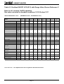
Gross heat Input
(kW)
55.5
73.3
93.2
129.9
162.0
208.0
242.0
275.2
348.5
Net heat Input
(kW)
50.0
66.0
84.0
117.0
146.0
187.4
218.0
248.0
314.0
Approx heat output
(kW)
47.4
61.2
78.4
110.2
134.5
177.7
205.3
230.4
293.4
Main Gas Orifice
(mm dia.)
8.5
10.0
10.0
14.5
14.5
14.5
14.5
14.5
Start Gas Orifice
(mm dia.)
5.0
6.0
7.0
7.0
7.0
7.0
Max Gas Rate
(m3/hr)
2.1
2.8
3.5
4.9
6.1
7.8
9.1
10.4
13.1
(kg/hr)
3.9
5.1
6.5
9.1
11.3
14.5
16.9
19.2
24.3
Lt/hr
7.7
10.1
12.9
17.9
22.3
28.7
33.4
37.9
48.1
Main Burner Gas Pressure
(mbar)
4.2
3.3
4.6
4.8
7.5
5.8
7.8
12.0
7.6
Start Gas Pressure
(mbar)
1.6
2.5
0.8
1.0
1.5
3.1
AZUR
BLU
BLU
BLU
BLU
BLU
BLU
BLU
BLU
60 AH
120 AH
120 AH
170 AH
250 AH
250S AH
350 AH
s
s
s
s
s
s
s
s
LPG
10.0
13.0
15.0
14
24.0
24.0
24.0
20.0
3.0
4.8
6.6
2.6
4.5
3.1
4.2
1.6
1.8
MBDLE
MBDLE
MBDLE
MBDLE
MBDLE
MBDLE
MBDLE
MBDLE
MBDLE
405
405
405
407
410
410
410
410
412
S
S
S
S
S
S
BURNER TYPE
Burner Head
Head Setting
(mm)
Air Setting
number
Valve Type
Main Gas
Valve Type
Start Gas
250R AH 250 AH
0 832 051 0 832 051 0 832 051 0 832 051 0 832 051 0 832 051
AIR PRESSURE SWITCH
SETTING
(mbar)
1.5
1.5
4.5
4.0
6.5
5.0
6.5
7.5
7.0
(mbar)
-0.05
-0.05
-0.09
-0.30
-0.05
-0.25
-0.17
0.10
0.45
3/4"
3/4"
3/4"
3/4"
1 1/4"
1 1/4"
1 1/4"
1 1/4"
1 1/4"
Max flue static pressure
norm. flue static pressure
Gas Connection
HEAD SETTING - See Adjustment Of The Firing Head in Ecoflam Instructions
Page 11
CABINET HEATER
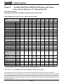
Table 2.6
Ecoflam HIGH/LOW or MODULATING Burner with Dungs
Valve, Burner Reference "H" Natural Gas G20
Data for all versions
Gas rates corrected to standard conditions 1013.25 mbar 15°C
ECOFLAM HIGH/LOW GAS BURNER WITH DUNGS GAS VALVES FOR NATURAL GAS G20
INLET PRESSURE 20 mbar (minimum 17mbar maximum 25mbar)
MODEL
PGP 15
ECA
PGP 20
ECA
PGP 30
ECA
PGP 40
ECA
PGP 50
ECA
PGP 60
ECA
PGP 70
ECA
PGP 80
ECA
PGP 100
ECA
Maximum Gross heat Input
(kW)
55.5
73.3
93.2
129.9
162.0
208.0
242.0
275.2
348.5
Maximum Net heat Input
(kW)
50.0
66.0
84.0
117.0
146.0
187.4
218.0
248.0
314.0
Minimum Gross heat Input
(kW)
38.9
51.3
65.2
90.9
113.4
145.6
169.4
192.6
244.0
Minimum net heat Input
(kW)
35.0
46.2
58.8
81.9
102.2
131.2
152.6
173.6
219.8
Approx Max heat output
(kW)
47.4
61.2
78.4
110.2
134.5
177.7
205.3
230.4
293.4
Start Gas Orifice
(mm dia.)
7.0
7.0
7.0
7.0
7.0
7.0
12.4
15.4
19.8
23.1
26.2
33.2
3
Max Gas Rate
(Sm /hr)
3
5.3
7.0
8.9
Min Gas Rate
(Sm /hr)
3.8
5.0
6.3
8.8
11.0
14.2
16.5
18.7
23.7
Main Burner Gas Pressure
(mbar)
4.9
2.4
3.3
4.1
6.7
5.2
6.7
8.0
8.6
Min. Burner Gas Pressure
(mbar)
3.2
2.8
2.4
2.3
3.7
2.5
3.4
4.3
5.4
Start Gas Pressure
(mbar)
1.1
1.8
0.6
0.7
0.9
1.0
BURNER TYPE
Burner Head
AZUR
BLU
BLU
BLU
BLU
BLU
BLU
BLU
BLU
60
120
120
170
250R
250
250
250
350
s
s
s
s
s
s
s
s
s
0.0
8.0
10.0
15.0
14
T.O.
T.O.
T.O.
T.O.
20°
13°
22°
18°
18°
18°
22°
25°
25°
Burner Injector
Head Setting
(mm)
Low Flame Air Orange Cam **
High Flame Air Red Cam
**
Gas Valve Setting
Valve Type
Main Gas
33°
40°
80°
30°
32°
30°
35°
55°
60°
0-1,5
0-1
0-1,4
0-1,4
0-1,4
0-1,4
0-1,4
0-1,4
0-1,4
MBVEF
MBVEF
MBVEF
MBVEF
MBVEF
MBVEF
MBVEF
MBVEF
MBVEF
407
407
407
407
412
412
412
412
412
Valve Type
Start Gas
S.I.T.
S.I.T.
S.I.T.
S.I.T.
S.I.T.
S.I.T.
832051
832051
832051
832051
832051
832051
AIR PRESSURE SWITCH
SETTING
(mbar)
1.5
1.5
1.5
1.0
1.5
1.5
1.5
2.0
2.5
(mbar)
-0.05
-0.05
-0.09
-0.30
-0.05
-0.25
-0.17
0.10
0.45
3/4"
3/4"
3/4"
3/4"
1 1/4"
1 1/4"
1 1/4"
1 1/4"
1 1/4"
Max flue static pressure
norm. flue static pressure
Gas Connection
S.= STANDARD
** Note the air setting is a guide only, the final setting is subject to the combustion testing.
HEAD SETTING - See Adjustment Of The Firing Head in Ecoflam Instructions
When setting the minimum firing rate a check must be made following the setting of the burner combustion .
The check is made by running the heater on low fire for a minimum of 15 minutes at the full transport air rate and at
typical ambient conditions. During the test check that the flue gas temperature does not fall below 150°C .Should the
flue gas temperature fall below 150°C then the low fire gas setting must be increased to a value that will achieve 150°C
flue gas temperature, otherwise condensation may form in the heat exchanger and flue causing rapid corrosion and
short operational life.
Page 12
CABINET HEATER
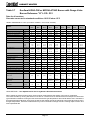
Table 2.7
Ecoflam HIGH/LOW or MODULATING Burner with Dungs Valve
Burner Reference "H" L.P.G. G31
Data for all versions
Gas rates corrected to standard conditions 1013.25 mbar 15°C
I N L E T P R E S S U R E 3 7 m b a r (m i n i m u m 2 5 m b a r, m a x i m u m 4 5 m b a r )
M ODEL
PGP 15
EC A
PGP 20
EC A
PGP 30
EC A
PGP 40
EC A
PGP 50
EC A
PGP 60
EC A
PGP 70
EC A
PGP 80
EC A
PGP 100
EC A
Max imu m G r o s s h e a t Input
(kW )
55.5
7 3 .3
9 3 .2
1 2 9 .9
162.0
208.0
242.0
275.2
348.5
Max imum Net heat In p u t
(kW )
50.0
6 6 .0
8 4 .0
1 1 7 .0
146.0
187.4
218.0
248.0
314.0
Min imu m G r o s s h e a t In p u t
(kW )
38.9
5 1 .3
6 5 .2
90.9
113.4
145.6
169.4
192.6
244.0
Min imum net heat In p u t
(kW )
35.0
4 6 .2
5 8 .8
81.9
102.2
131.2
152.6
173.6
219.8
A p p r o x h e a t output (Net)
(kW )
47.4
6 1 .2
7 8 .4
1 1 0 .2
134.5
177.7
205.3
230.4
293.4
Mai n G a s O r if ic e
(mm dia.)
8 .5
1 0 .0
1 0 .0
14.5
14.5
14.5
14.5
14.5
N/A
Start Gas O r if ic e
(mm dia.)
7.0
7.0
7.0
7.0
7.0
7.0
Max G a s Rate
(Sm3/hr)
2.09
2.76
3.51
4.89
6.10
7.83
9.11
10.36
13.12
Kg/h
3.87
5.11
6.49
9.05
11.29
14.49
16.86
19.18
24.29
Ltr/h
7.65
10.11
12.85
17.91
22.34
28.68
33.37
37.94
48.05
(Sm3/hr)
1.46
1.93
2.46
3.42
4.27
5.48
6.38
7 .25
9.18
Kg/h
2.71
3.58
4.55
6.34
7.90
10.15
11.80
13.42
17.00
Ltr/h
5.36
7.07
9.00
12.54
15.64
20.08
23.36
26.56
33.64
Min G a s R a t e
Mai n B u r n e r G a s Pr e s s u r e
(mbar)
4 .3
5.7
4.7
3.1
5.9
5.3
7.2
9.0
6.4
Min . B u r n e r G a s Pr e s s u r e
(mbar)
2 .3
2.9
1.4
1.6
2.0
2.3
2.5
3.2
2.0
Start Gas Pr e s s u r e
(mbar)
1.1
1.7
0.6
0.7
0.7
1.5
BURNER T Y P E
Burner Head
A Z UR
BLU
BLU
BLU
BLU
BLU
BLU
BLU
BLU
60
120
120
170
250R
250
250
250
350
s
s
s
s
s
s
s
s
B u r n e r In je c t o r
Head Setting
(mm)
L o w Flame A ir O r a n g e C a m **
Hig h F la m e A ir Red Cam
s
LPG
**
G a s V a lv e S e t tin g
V a lv e Ty p e
Main Gas
0 .0
8.0
1 0 .0
15.0
14
T.O.
T.O.
T.O.
T.O.
20°
13°
22°
18°
18°
18°
22°
25°
25°
33°
40°
80°
30°
32°
30°
35°
55°
60°
0 - 1 ,4
0 ,3-0,9
0-1,1
0-1,1
0-1,1
0-1,4
0-1,4
0-1,5
0-0,85
MBV EF
MBV EF
MBV EF
MBV EF
MBV EF
MBV EF
MBV EF
MBV EF
MBV EF
407
407
407
407
412
412
412
412
412
V a lv e Ty p e
Start Gas
S.I.T.
S .I.T.
S.I.T.
S.I.T.
S.I.T.
S.I.T.
832051
832051
832051
832051
832051
832051
1.0
1.5
1.5
1.5
2.0
2.5
A IR PRESSURE SW ITCH
SETTING
(mbar)
1 .5
1.5
1.5
Max f lue static p r e s s u r e
HEAD SETTING - See Adjustment Of The Firing Head in Ecoflam Instructions
When setting the minimum firing rate a check must be made following the setting of the burner combustion .
The check is made by running the heater on low fire for a minimum of 15 minutes at the full transport air rate and at
typical ambient conditions. During the test check that the flue gas temperature does not fall below 150°C .Should the
flue gas temperature fall below 150°C then the low fire gas setting must be increased to a value that will achieve 150°C
flue gas temperature, otherwise condensation may form in the heat exchanger and flue causing rapid corrosion and
short operational life.
Page 13
CABINET HEATER
2.2.3
Sequence of Events
The operating sequence is as follows:
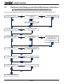
With the external controls on and calling for heat, the burner fan and electric ignition will switch on.
After a combustion air purge of approximately 12 seconds, the oil solenoid valve will open and the burner will fire.
After another 5 seconds the electric ignition is turned off and the burner will go to its normal run position.
The photo cell monitors the safe presence of the flame continuously.
When the temperature control is satisfied, the control box will turn off all its outputs simultaneously, and returns to the
rest position for the beginning of the next sequence.
2.2.4
Fault Conditions
If at any stage during normal running the photo electric cell fails to detect the flame, the control will switch off and make
an instant restart attempt. If the flame signal is still missing “lockout” will occur.
If the flame is not detected by the photo cell during a normal start, there will be no restart attempt and “lockout” will
occur in approximately 17 seconds after the start.
If a flame is detected during the first 12 seconds (purge) the solenoid valve will not open and the control will “lockout”.
For control sequence see Fig. 2.1.
2.3
Control Box - Gas Fired Heaters
(See also the Burner Manufacturer's Instructions)
High /Low and Modulating burners although following the general sequence as described below also have extra functional
stages related to air damper positions. Refer to burner manufacturers instructions for further detail.
Ecoflam gas burner have only one pressure switch which is configured to cover both available combustion air and
reaction to increases in combustion chamber pressure.
2.3.1
Description of Gas Fired Heater Control Box
The gas fired burner fitted to all COMBAT® cabinet heaters is controlled by a full sequence plug-in control box. This
control ensures the safe start and stop sequence and also monitors the safe presence of a flame and burner air
pressure.
The Models 15 to 30 are wired for direct ignition of the main flame. All other models are wired for ignition of a start gas
flame as first stage and then the main gas flame as the second stage.
2.3.2
Sequence of Events
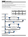
The operating sequence is as follows:
With the external controls on and calling for heat, and the air pressure switch at rest, (contacts n.c. closed), the burner
fan will switch on after a short wait for the control to "self check."
Note: If the air pressure switch contacts (n.c.) are open there will be no start.
Page 15
CABINET HEATER
For Ecoflam High/Low or Modulating burners then the Dungs gas valve has extra features as it is an air/gas ratio
control valve.Please refer to the manufacturers instructions regarding the setting of these controls.
The design of the gas train circuits is shown in Fig 2.5.
Orifice Plate
Most models require the fitting of a restrictor (orifice) plate between the main gas valve outlet and the burner to prevent
the burner from being over fired and provide suitable operating conditions for the gas valves.
Orifice Plate Position
Ecoflam Burner
For all models this will be fitted into the special union between the main valve and the burner at the point where the gas
supply enters the heater.
2.7.1.1
Start Gas Valves
For models PGP015 to PGP030 there is no start gas valve fitted.
For all other models the start gas train is fitted with a pressure regulator and two start gas safety shut off valves.
The start gas regulator is used to adjust the burner firing rate during the start gas phase of these models.
2.7.1.2
Main Gas Valves
Figure 2.6 shows the position of the burner pressure regulation adjustment. This must be used to set the burner
pressure as in the Data Tables as described in Section 5.
Note: For Ecoflam High/Low or Modulating burners then the Dungs gas valve has extra features as it is an air/gas
ratio control valve.Please refer to the manufacturers instructions regarding the setting of these controls.
2.7.1.3
Throughput Adjuster
Fig 2.6 shows that these types of valve have a throughput adjuster fitted to the second main gas valve.
This will be factory set at fully open on new appliances and will need no further adjustment.
When replacing a gas valve ensure that this device is set in the fully open position by releasing the locking screw and
turning the ’V MAX” fully counter clockwise towards the " + " sign and then re-tightening the locking screw.
2.7.1.4
Rate of Opening
Fig. 2.6 also shows a slow opening adjustment. This device is a hydraulic damper which slows down the rate of
opening of the second main gas valve to give a smooth main gas ignition.
This is preset at the factory at the slowest setting and will need no further adjustment.
If a new valve is fitted than remove the plastic screw-on cap and with a small screw driver turn the “V start” screw fully
clockwise towards the " - " sign. Refit the plastic cover.
Page 19
CABINET HEATER
Section 3.
3.1
Installation Requirements
Required Standards
It is important that all appliances are installed by competent persons, in accordance with the relevant requirements of
all the relevant rules and laws in force.
Gas heaters must be installed by a suitably qualified installer. Failure to install appliances correctly could lead to
prosecution. It is in your own interest and that of safety to ensure that the law is complied with.
The main relevant regulations for installation within the UK are:
GAS SAFETY (INSTALLATIONS & USE) REGULATIONS 1984 AND IT'S AMENDMENTS - 1996.
BS6230
-
SPECIFICATION FOR THE INSTALLATION OF GAS FIRED FORCED CONVECTION
AIR HEATERS FOR COMMERCIAL AND INDUSTRIAL SPACE HEATING OF
RATED INPUT EXCEEDING 60Kw.
Note: Although written for gas fired heaters the requirements of this standard should be
observed for oil fired heaters, except for the fuel supply.
BS5588
-
PARTS 2 & 3 FIRE PRECAUTIONS IN THE DESIGN & CONSTRUCTION OF BUILDINGS
BS6891
-
LOW PRESSURE INSTALLATION PIPES
BS5410
CODES OF PRACTICE FOR OIL FIRING. PART 2 INSTALLATIONS OF 44Kw AND
ABOVE OUTPUT CAPACITY FOR SPACE HEATERS, HOT WATER AND STEAM
SUPPLY PURPOSES
INSTITUTE OF GAS ENGINEERS DOCUMENT IGE/UP/2
THE BUILDING REGULATIONS
THE IEE REGULATIONS
THE HEALTH & SAFETY AT WORK etc. ACTS
THE REQUIREMENTS OF LOCAL AUTHORITY, FIRE OFFICER AND INSURANCE COMPANY
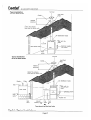
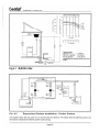
The installation will be similar to that shown on Fig. 3.1.
WARNING
HEATERS SHOULD NOT BE INSTALLED IN A CORROSIVE OR SOLVENT ATMOSPHERE
(I.E. NEAR PLATING OR DEGREASING PLANT), IN AREAS WHERE THERE IS A
FIRE RISK, OR ANY OTHER ENVIRONMENT WHICH IS DETRIMENTAL TO THE HEATER OR IT'S
OPERATION.
CONSULT BS 6230 FOR FURTHER INFORMATION ON HAZARDOUS AREAS
Page 20
CABINET HEATER
3.2
Location of the Heater
The COMBAT® cabinet heater range is designed to be installed floor standing in the vertical mode.
Special versions which are supplied with steel channels to support the heater, are available to be mounted in the
horizontal mode.
All Models: All heaters are designed to be installed within the heated area but may be sited in a separate room with the
heated air carried by properly designed ductwork supplied by the installer. If used in this remote mode the room and
frost thermostats must be within the heated space, and connected as described in Section 4.3 and the return air should
be ducted direct to the heater return air spigots.
Note: For clarity the clearances and references to cabinet panels refer to the heater installed in the floor standing
vertical mode.
Horizontal Models: When installed in the horizontal mode the heater will normally lie on its left hand side when viewed
from the burner. The same clearances and comments on panels must be assumed for the heater installed in this mode
except for the side the heater lies on. The heater should be placed on a firm level surface that can adequately support
its weight (See Table 2.1 for weight details) and is of non combustible material.
When siting heaters other than at floor level consideration must be given to providing safe access for engineers to
carry out commissioning, routine servicing and repair functions.
Such access must comply with local safety regulations.
3.2.1
Clearances
There must be a clear area of at least 0.6 m from each side and to the rear of the heater and not less than 2 m at the
front. For all models except High Flow heaters, the pressure relief door is at the rear of the heater; it is important that
the minimum clearance at the rear of the heater is not less than 0.3 m to ensure safe operation.
IMPORTANT: For maintenance of the heater all of the upper panels need to be removed for the checking and replacement
of insulation. Also the lower side panels are the only access for removal of the main fan, it is therefore necessary to
have a minimum clear area of at least 1 m to one of the sides for this purpose.
There should be a clear distance of at least 4 m from the discharge heads to ensure free flow of warm air.
3.3
Air Supply (Plant Rooms)
It is important to ensure that there is adequate air supply at all times for both combustion and heating requirements.
Particular attention must be paid to this point when the heater is installed in a separate room. Ventilation should prevent
the Plant room temperature exceeding 32°C.
Any plant room containing air heaters will require permanent air vents direct to outside air in compliance with BS 6230.
The air supply to and from the heater distrubution fan must be fully ducted through the plant room to the heater spigots
to ensure that the fan does not cause negative pressures in the room.
Where mechanical ventilation is used, it shall be by mechanical inlet and with either natural or mechanical extraction.
Systems of ventilation employing mechanical extraction and natural air inlet shall not be used.
Automatic means, such as interlocks, shall be provided for installations where equipment failures can lead to hazardous
situations developing.
Page 22
CABINET HEATER
3.3.1
Return Air Ducting
In installations employing recirculation or fresh air ducting this ducting shall comply with the following.
(a)
There shall be an unobstructed air path connected directly to the heater.
(b)
The return air or fresh air shall be connected by ducting directly to the air inlet on the heater.
(c)
Where automatic or manual dampers are provided for operational adjustment in these ducts, they shall
be proved in the correct position during the operation of the burner.
The main fan requires a minimum free air return path of 1 m2 per 197 kW of heater output or 0.33m2
whichever is the greater.
Note: When heaters are installed in the horizontal mode, connected to distribution ducting and/or inlet ducting then the
natural convected air flow through the heater, before the main fan turns on, may be disrupted.
To ensure correct operation of the fan under these circumstances, all COMBAT® cabinet heaters designed for horizontal
mounting have the main fan designed to operate in conjunction with the burner sequence by the use of a time delay or
direct acting relay.
It is strongly recommended that when any heater is connected to installation ducting that a similar approach to the fan
control is used. Any such control must be in parallel with the fan thermostat so that the fan "run on" feature is still able
to operate (see the wiring diagrams in Section 6 for details).
3.4
Building Ventilation
In buildings having a design air change rate of less than 0.5/h, and where heaters are to be installed in heated spaces
having a volume less than 2.2 m³ per kilowatt of total rated heat input for heaters fitted with forced or induced draught
burners; grilles shall be provided at low level (i.e. below the level of the appliance flue connection) except that:
Most traditional building constructions will provide air changes of at least 0.5/h without the need for ventilation openings.
For heaters installed in buildings with a design air change rate 0.5/h or greater, and where the volume of the heated
space is greater than 4.7 m³ per kilowatt of total rated heat input, as appropriate additional high and low level ventilation
will not be required.
Where necessary ventilation air shall be taken from an outside point where it is not likely to be contaminated, for
example with smells, road vehicle exhausts, dry cleaners, exhausts, solvents, etc.
The minimum quantity of outside air required for ventilation shall be at least that required for personnel within the
building.
Where the heaters are located in the heated space the air supply requirement is not necessarily the sum of the
individual requirements for combustion, ventilation and dilution air, and fresh air, but the greater individual requirement.
Where there are any flued appliances in the room and where outside air is supplied mechanically and there is mechanical
extraction, the design extract rate shall be 5% to 10% less than the design inlet rate so that the room will be at a higher
pressure than the outside air.
Page 23
CABINET HEATER
Section 4. Installation of the Heater
4.1
Flue
Each heater must be fitted with at least one metre of an individual and correctly sized stainless steel flue, (see Table
2.1 for flue sizes) which must carry all products of combustion to outside the building in accordance with these instructions
and local regulations.
Suitable flue may be obtained from Roberts-Gordon.
No other appliance may be connected to this flue.
The flue must be terminated at least one meter higher than the section of the roof it intersects (see Fig 3.1). Furthermore
if the point of intersection with the roof is within 2.5m of a nearby structure, the terminal must be at least one meter
above that structure .
It is important that the flue is designed to prevent the adverse effects of down draughts causing excess pressure in the
combustion circuit. If such excess pressure is being produced, (see maximum flue pressure in the data tables), then it
is recommended that the terminal is at least one metre higher than the highest point of the roof .
The top of the flue should be fitted with a terminal or rain cap.
If a flue extends more than 2 m above the roof it should be supported by guy wires. (See Fig. 3.1).
90° bends and horizontal pipe must not be used in flues except for the immediate flue connection to horizontally
mounted heaters where the transition to a vertical flue must be within as short a distance from the heater as is possible.
Normally the transition to vertical will be no more than one metre from the flue spigot.. As a guide where it is necessary
to use 135° bends to offset a flue, at least 1 m of vertical flue must be added to the minimum requirement for every 2
x 135° bends or 0.3 m of non vertical flue.
No draught diverters or stabilisers should be fitted to the flue.
The assembly of the flues from the heater to below the weather sealing collar should be with their sockets facing
upwards. Above the weather sealing collar the sockets should be facing downwards. The joints are to be secured with
monel blind rivets or sheradized P.K. screws. If condensation is likely to occur in the flue, then provision should be
made for drainage.
The flue should be sealed into the female spigot of the heater using a heat resistant rope and fire cement.
If the flue passes through a wall or ceiling of combustible material it must be enclosed by a sleeve of none combustible
material and separated from the sleeve by at least 25 mm air gap. The temperature of any combustible material near
the flue or heater must not exceed 65°C when the heater is in operation. The flue must also be at least 50 mm from any
other combustible material. The joints between the flue and roof or wall must be made good to prevent water ingress.
The flue should be installed and supported so that the heater does not carry any flue weight and the installation must
comply with the relevant codes of practice (see Section 3.1).
Page 24
CABINET HEATER
4.2
Electrical Supply
A 230 volt 50 Hz single phase supply is required for all heater Models 015 to 030 connected to the heater terminals L 1,
N & Earth.
Standard models 040 to 0100, and all High Flow models require a 400 volt 50 Hz three phase and neutral supply
connected to the heater terminals L1, L2,L3, N, and Earth.
All heaters and controls must be correctly earthed. All external wiring must comply with the relevant IEE and local
regulations and be carried out by a qualified electrician.
It is important that "L & N" polarity is correct for these heaters as incorrect polarity may prevent the burner control box
from operating properly. It is also important that the voltage between N and earth is at 0v and can never exceed 15v.
Note: Roberts-Gordon can supply a special isolating transformer to provide a suitable treatment of the supply to the
burner, where there is a problem on the electrical supply with respect to voltage between N and Earth.
An isolator with a contact separation of at least 3 mm on all poles should be installed adjacent to the heater, but not
attached to it, to disconnect all supplies to the heater and where necessary to isolate the remote control panel.
The final connection to the heater should be made in metal sleeved flexible cable or flexible conduit to the main
terminal block under the front lower panel of the heater using 1 sq. mm cable on all models (except Model 0100 and
High Flow models with 5.5kW or 7.5kW motors) when 1.5 sq. mm cable should be used. Cable entry is provided into
the rear horizontal frame of the cabinet.
4.3
Remote Controls
4.3.1
Individual Controls
All the heater controls for the COMBAT® range are to be site wired remote from the heater. The minimum control would
be a room temperature control thermostat wired between terminals 2 and 3 of the heater. Extra controls will be required
for burners with High.Low or Modulating operatein see 4.3.1.1
All controls must be voltage free from external sources.
Where a time switch and/or manual switch are installed then these should be wired in series with the control thermostat.
Siting of Thermostats or Temperature Sensors
When siting a remote control thermostat or temperature sensor it should be fitted on a wall or column at a height of
1.5m from the floor of the room being heated.
It is important for comfort and fuel economy to site the thermostat where it will monitor an average room temperature
i.e. keep clear of draughts from doors or windows or from the direct path of heated air from the heater. Areas of little air
movement, e.g. corners, should also be avoided.
Where a remote Frost Thermostat is being used, it should be sited within the heated space adjacent to the most
vulnerable equipment that requires protection.
Page 25
CABINET HEATER
4.3.1.1 Controls for High/ Low Burner Operation
For heaters that incorporate an Ecoflam High/Low burner then the on site controls will need to provide the two stage
signal to operate these burners.
This is best provided by a two stage thermostat so that the setting of the thermostat ensures that the two set points are
correctly related.
The thermostat may control the heater outlet temperature if the heater is designed for a duct distribution system or the
room temperature.
The site wiring will be across terminals 2 & 3 for any time control and the on/off function of the burner (stage two) and
across terminal 2 & 8 for the low fire (first stage ) setting.
The burner will then operate as follows:
• Temperatures from cold up to the first stage set point • Temperatures above first set point up to the second set point • Temperatures above the second set point -
Full fire at the maximum rate
Low fire at the minimum rate
Off
4.3.1.2 Controls for Fully Modulating Burners
For heaters that incorporate an Ecoflam fully modulating burner then the Landis & Staefa temperature control is provided
with the heater. The Landis & Staefa control provides the temperature control and the on site wiring of the temperature
sensor is required along with any time control required on site.
The heater will normally be controlled by the temperature of the air in the outlet duct, but it is possible to control on room
temperature.
The position of the sensor in the outlet duct is to be determined on site as all installations differ.
By using a suitable thermometer select a position in the outlet duct approximately 1 meter from the heater and look for
a position across the cross section of the duct that provides a reasonable average of the temperatures found. Mount
the sensor as close to this position as possible for best results.
It must be noted that when operating at reduced heat input the leaving air temperature may be low when controlled on
room temperature.
The Time control and any other on/off controls will be across terminals 2 & 3.
The sensor will be connected to terminals 8 & 9
The operation will then be:
• The burner will fire and once the burner sequence reaches the release to modulation stage the Landis & Staefa
control will begin to monitor the outlet temperature.
• The control will then adjust the burner input continuously to attempt to maintain the set temperature on the control.
• Should the temperature continue to rise even though the burner is operating at minimum fire then the control will turn
off the burner until the temperature falls again when the burner will restart automatically.
If a switch etc. is required to turn on the main fan for ventilation, then this must be voltage free, from external sources,
and may be connected between: Terminals L1 and 1 for all models 15 to 30 or Terminals 2 and 1 for all other models.
Page 26
CABINET HEATER
4.4
Fuel Oil Supply
4.4.1
Fuel Storage Tank
The fuel oil storage tank should be located as close as possible to the heater, but outside of the building. The tank must
not be mounted directly on the ground but should be raised clear of the ground on suitable trestles, and/or located in a
concrete or metal catch pit. The catch pit should be constructed to have a net volume of at least 10% greater than the
volume of the tank, and be oil tight.
4.4.2
Fuel Pipes
The fuel pipes must be sized to ensure an adequate supply of oil to the entire installation. Galvanised pipe must not be
used on oil installations (see Table 2.3 for fuel usage).
The fuel pipe must terminate at each heater with an isolating manual valve, a fire valve and a fuel filter (see Fig. 3.1).
The fusible link of the fire valve should be installed so as to be 100 mm (4 inches) above the burner.
The heater’s oil burner pump inlet is provided with a flexible oil line which should be used for the final connection.
When making the final connection to the heater, care should be taken not to impede the removal of any of the removable
panels of the heater. All COMBAT® oil fired cabinet heaters are supplied with burner pumps fitted for one pipe systems.
4.4.3
Gravity Feed System
The simplest installation is a gravity feed system as in Fig. 3.1. This system relies on the head of the fuel in the tank to
push the fuel through the system.
4.4.4
B. M. Oil Lifter
Where a gravity feed system cannot be used, a B.M. Oil Lifter may be used for small installations up to the equivalent
to a single model 050 on minimum lift or a single model 020 on maximum lift (see Fig 4.1).
The fuel output from the oil lifter is gravity fed.
The B.M. Oil Lifter requires a constant 230 volt 50 Hz single phase electrical supply adjacent to its position. The
maximum pipe size to be used on the suction side is 1/4" I.D. (5/16" O.D. (8mm)); for maximum loading of oil lifters
refer to graph on Fig. 4.1. Consult the manufacturers information regarding the need to prime these devices.
4.4.5
Pressurised Systems
For larger installations a pressurised system may be used. In this type of system a pump draws fuel from the tank and
then pushes it through the installation under pressure. The pressure is controlled at the pump by a pressure relief valve
at approximately 0.8 BAR (12 psi ).
When a pressurised system is used, a pressure reducing valve set at approximately 0.3 BAR (5 psi), should be
installed on the fuel inlet to each heater after the manual isolating valve. This is to protect the oil burner pump from the
danger of possible over pressure under fault conditions.
Fig. 4.2 shows a suggested scheme.
The electrical supply for the pumped installation will depend upon the type of pumps chosen, but will normally be set to
run continuously.
Page 27
CABINET HEATER
4.5
Gas Supply
General
The installation must comply with local laws and regulations, and the complete installation including the meter, where
fitted, must be purged and tested for soundness.
The gas supply must be adequately sized to carry a sufficient quantity of gas at the specified pressure at the heater
inlet whilst firing (see data tables in section 2).
The gas supply must be sized to supply the correct amount of gas to the heater under all load conditions.
It will generally be required to use installation pipes of a larger diameter than the heater inlet connection.
The supply should terminate at each heater with a service cock and a union so as to facilitate the removal of the gas
train for servicing (see Fig 3.1).
Natural Gas
The gas meter and service must be checked by the local gas supply undertaking to ensure that it is adequate to deal
with the total connected load of the completed installation.
Each heater must be provided with gas having the inlet pressure controlled at 20 mbar (17mbar - 25mbar)
L.P.G.
For L.P.G applications each heater must be provided with gas having an inlet pressure controlled at 37mbar (25mbar
- 45mbar) for propane (G31).
Page 29
CABINET HEATER
Section 5.
Commissioning the Heater
5.1
Commissioning is to be carried out only by competent personnel. Gas fired heaters must be commissioned by a
C.O.R.G.I. registered engineer.
Any faults found during this procedure must be corrected before progressing any further with the commission.
It is important to read and understand this section and the burner Manufacturer’s Instructions fully before commencing
the commissioning of the air heater.
No attempt to start any part of the air heater should be made prior to ensuring that it has been correctly installed and
that the components are satisfactory for the voltage, or pressures that are specified.
Follow Section 5.1 for pre commissioning checks and then:
Section 5.2 for oil fired heaters along with the burner manufacturer’s instructions and
Section 5.3 for gas fired heaters along with the burner manufacturer’s instructions.
Note: manufactures instructions may be general instructions for the application of their burners to any product. Where
specific detailed settings are referred to in this instructions book they should be followed, as they represent the agreed
settings when used on COMBAT® Cabinet Heaters.
Note: During the commissioning instructions, reference is made to the information in the Data Tables in Section 2. It
is important that reference is made only to the Data Table which relates to the burner option fitted to the heater as
indicated by the burner reference letter on the data plate and for the correct fuel type.
Any manufacturing seals that are broken during the on site commissioning must be re-sealed following the completion
of the commissioning so that subsequent adjustment by unauthorised persons is deterred.
5.1.1
Pre Commission Checks - All Heaters
5.1.1.2
Electrical Tests
Ensure that the electrical supply has been correctly connected. This to include:
5.1.1.3
Earth Continuity Check
The earth continuity must be a resistance of less than 0.1 ohm when a test is taken between any appliance’s earth point
and the main incoming earth at the isolator.
If a higher reading than this is obtained, the fault must be traced and rectified, preferably by an electrician, before
continuing with the commission.
Page 30
CABINET HEATER
5.1.1.4
Polarity Test - Single phase
Connect one lead of a suitable voltmeter to earth and connect the other lead to the live supply terminal at the heater L1.
Turn on power to heater. A reading of approximately 230 volts AC 50Hz should be found.
The same result should be obtained by connecting the test leads from live to neutral.
Connecting the voltmeter between Neutral ‘N’ and Earth should give a reading of 0 volts. If these tests do not conform
to the above there is a fault which must be rectified before progressing further with the commission. An electrician
should be consulted to carry out this work.
Note: The burner control box may not operate with a neutral to earth voltage above 15v. and may be unreliable at any
reading other than 0.
5.1.1.5
Polarity Test - Three Phase
Connect one lead of a suitable voltmeter to earth and connect the other lead to each live supply terminal at the heater
in turn L1,L2 & L3. A voltage of a approximately 230v should be found between each phase and Earth or Neutral.
The voltage between and two phases should be approximately 400v.
See 'Single Phase' above for testing Neutral to Earth.
5.1.1.6
Fan Rotation Check
Switch on the electricity supply at the isolator and the manual switch to 'fan on' (if there is no remote fan switch installed
then press in the white button of the combination fan/limit thermostat). On three phase heaters check the rotation of the
main air moving fan. This should be clockwise looking at the drive end. If rotation is not correct, turn off the isolator and
change over any two of the incoming supply phases and recheck. It will be necessary to remove the lower front or right
hand side panel to see fan rotation.
5.1.2
Electrical Settings
5.1.2.1
Combination Fan/Limit Thermostat Settings Check
Check the settings on the combination fan/limit thermostat. The three hands from left to right should be set approximately
as follows:
Any manufacturing seals that are broken during the on site commissioning must be re-sealed following the completion
of the commissioning so that subsequent adjustment by unauthorised persons is deterred.
Hand 1
Hand 2
Hand 3
Fan Off temp
Fan On temp
Limit temp
38°C
(100°F)
60-65°C
(140-150°F)
110°C (230°F)
WARNING
DO NOT ROTATE THE DIAL BY HAND AS THIS MAY CAUSE PERMANENT DAMAGE TO THE MECHANISM.
The link must be removed between the two switches on this device (see Fig. 2.3).
5.1.2.2
Fan Motor Overload Check
On three phase belt drive heaters check the correct setting of the fan motor overload (See 2.4) this should be 0.2 amps
above the rated running current on the heater data plate or see Table 2.1.
Page 31
CABINET HEATER
5.2
Commissioning the Burner - OIL HEATERS
Check all valves between the fuel tank and the heater are open, including the fire valve (i.e. cable is tight).
Ensure that oil is available at the heater inlet (see Fig. 3.1) and that the air has been vented from the fuel pipe
installation. This can be achieved by slackening the bleed screw on top of the fuel filter.
i) On pressurised systems; check that the installation is running at the correct pressure (see 4.4.5).
ii) B.M. Oil Lifters will need priming (see manufacturer’s leaflet).
5.2.1
Ensure the burner head and air damper settings are adjusted in accordance with the Data Tables for the correct burner
and that the correct atomising nozzle is fitted (See burner reference letter on the heater data plate).
5.2.2
Preparation of Test for Burner Pressure
Attach a pressure gauge 0-15 BAR (0 - 200 psi) to the burner pump pressure test port. (See Manufacturers Information)
A test manifold gives the facility for the connection of the pressure gauge and venting of the pump.
5.2.3
i)
Switching On
Operate the external controls to turn the heater on. (Heat ON position).
Note: The burner plug and socket may be used to turn off the burner during commissioning.
ii)
If the ‘lockout reset’ button is illuminated press in to reset.
The combustion air fan and electric ignition should work immediately (the latter can be heard as a crackling sound at
the burner).
Section 2.2. gives full sequence details.
Vent the burner oil pump at the same time (the pump must be running).
If the burner goes to ‘lockout’ before the pump has vented, reset the control box, and repeat 5.2.3. until all the air has
been vented from the pump and the burner fires.
Note: Wait one minute before attempting to reset the control box.
WARNING
THE CONTROL SHOULD NOT BE RESET FROM LOCKOUT MORE THAN THREE TIMES WITHOUT
IDENTIFYING AND CORRECTING THE CAUSE. RESIDUAL FUEL OIL IN A COMBUSTION CHAMBER IS AN
EXPLOSION RISK.
Page 32
CABINET HEATER
5.2.4
Adjust Burner Oil Pressure
Adjust the burner oil pressure to the value for model given in the data table for the burner reference letter and burner
manufacturers information for details of the burner oil pump.
When completed turn off burner and remove test gauge and refit port plug.
5.2.5
Set Combustion Air
The combustion air must now be set. This is carried out by measuring the emissions in the flue at a point within one
metre from the outlet of the heater and adjusting for the highest carbon dioxide (CO2) levels obtainable, usually 10.5 11.5%, whilst making little or no smoke (smoke number 0 -1). Tests must be carried out with all covers fitted and after
the heater has been running for at least 15 minutes.
Closing the combustion air damper (reducing number) will raise both CO2 and smoke number. Conversely opening the
air damper (rising number) will reduce these levels.
5.2.6
Completion
Recheck and note all results and settings on the commissioning data sheet at the rear of this these instructions. Test
burner for correct start and stop operation, several times. Check that all safety devices operate correctly.
Inspect the heater and pipework for any oil leaks and repair where necessary.
5.2.7
Hand Over
Replace all covers panels or caps removed during commissioning securely. Hand these instructions to the user or
leave them at the heater. Explain to the user the operation of the heater, this should include:
Starting and stopping the heater.
How to set the time switch (where fitted)
How to set the thermostats and their position.
What to do if the heater does not operate.
How to vent air from the fuel system.
How to measure the fuel in the storage tank.
The grade of fuel to be used.
Any other points on the installation that the user may need to know.
Page 33
CABINET HEATER
5.3
Commissioning the Burner - GAS HEATERS
Follow section 5.1.1 to 5.1.2.2 for preliminary checks.
Note: Ecoflam High/Low and Modulating burners have extra specific requirements. Follow the manufacturers
instructions using the setting data provided in these instructions in section 2.
It is important when setting the minimum firing rate to check on site that the flue temperature does not fall below 150°C
when running for prolongued periods of low fire. The minimum firing rate must be increased above the minimum stated
in the data tables to ensure this situation. Failure to take acount of flue temperature will cause the combustion products
to condense. This will cause water leakage problems and heat exchanger life problems.
5.3.1
Preparation of the Burner
Ensure the burner head, air damper and pressure switch settings are adjusted in accordance with the Data Tables for
the correct burner (see burner reference letter on the data plate).
5.3.2
Carry Out A Dry Run
To prove the safe operation of the controls allow the burner to cycle without gas turned on.
With the gas service cock still in the off position, turn on the electric supply to the heater and observe the burner
operation as it goes through the cycle of events.
5.3.3
Switching On
Operate the external controls to turn on the heater (Heat ON position). If the ‘lockout reset’ button on the burner control
box is illuminated, press in to reset.
Note: The burner plug and socket may be used to turn the burner off and on during commissioning.
After a short delay the combustion air fan should run. (see Section 2 for full sequence times).
After the purge period, the electric ignition will turn on (this can usually be heard as a crackling sound at the burner),
followed quickly by the start gas valve (Main Gas Valve for models 15 to 30) opening.
The control box will now go to ‘lockout’ as no flame will be present.
If the control box goes to ‘lockout’ after 5 seconds of the purge period, this may be due to the air pressure switch being
set too high, (turn it's adjustment down slightly), or the burner fan not being connected correctly (see Burner
Manufacturer’s Instructions and reset the lockout button).
Before continuing with the commission carry out the gas valve proving tests described in the Burner Manufacturer’s
Instructions.
Page 34
CABINET HEATER
5.3.4
Fire the Burner for Dungs Combination Gas Valves
Open the gas isolating valve.
Connect a suitable pressure gauge to the burner pressure test point.
On models 040 or larger, to ensure that start gas only may pass to the burner, remove the gas valve electrical plug for
main gas valve. Reset the lockout button of the control box and carry out operation 5.3.4 again. The burner should now
fire. If lockout should occur when the start gas valve energises (or main gas valve for models up to 030), repeat 3 or 4
times.
If after several attempts, the burner does not fire then turn the start gas governor adjusting screw (or main gas governor
for models 015 to 030) 3 turns clockwise (see 5.3.6 below) and repeat until the burner fires.
5.3.5
Initial Setting
Note: Miss out this stage for models 015 to 030
Once firing, the start gas pressure should be set to the value given in the Data Tables for the burner type and the
model concerned (see burner reference letter on data plate). This is carried out by turning the governor adjusting screw
(accessed under the screw on cover) clockwise to increase pressure, or vice versa.
5.3.6
Set Gas Rate
Switch off and refit the main gas valve plug, removed earlier to allow the main gas valve to operate. Switch on again
and allow the burner fire and to settle for a few minutes. Adjust the main gas burner pressure to the value given in the
relevant Data Table for the model concerned using the Main Gas Regulator accessed under the swivel cover (see Figs
2.6 & 2.7).
The results of setting the gas flow rate by using burner pressure only can lead to quite wide variations in heat input due
to the nature of the burners used.
It is important to check that the gas rate set during the commissioning is within ± 5% of the required flow rate.
This may be achieved by wherever possible checking the gas flow to the heater by using the gas meter and timing the
flow through the meter. The results should be compared with the required flow rate for the model given in the Data
Tables, adjusting the burner pressure to correct for any error.
Note: This must be carried out with all other appliances turned off, including any pilots.
5.3.7
Set Combustion Air - All Gas Valve Types
The combustion air must now be set. This is carried out by measuring the emissions in the flue at a point within one
metre of the outlet from the heater and adjusting for the highest concentrations of carbon dioxide (CO2) obtainable,
usually 9.5% to 10% for natural gas and 11% for L.P.G. whilst making little or no carbon monoxide (CO); 10 parts per
million (0.001%) is the maximum recommended. These tests should be carried out with all covers and panels fitted.
To adjust for these results:
Closing the combustion air damper will increase these values.
Opening the damper will reduce these values.
Once adjusted to the optimum combustion setting ensure that the combustion air damper is locked into position (see
Burner Manufacturer's Instructions).
Due to the interaction between combustion air and burner gas pressure it is now advisable to repeat from 5.3.6.
Page 35
CABINET HEATER
5.3.9
Set Air Pressure Switch
WARNING:
SETTING OF THE AIR PRESSURE SWITCH MUST ONLY BE CARRIED OUT AS
PART OF A COMPLETE COMMISSION INCLUDING COMBUSTION TESTS.
See manufacturers information.
To set a pressure switch:
Remove the cover of the air pressure switch - Note: THIS EXPOSES LIVE TERMINALS.
With the burner firing as set up previously, turn the setting dial of the pressure switch to the setting indicated in the data
table for the model and burner reference concerned.
The pressure switches are designed to prevent the burner from producing dangerous combustion products under
adverse conditions such as reduced supply voltage and blocked flues.
It is important that the settings indicated in the Data Tables are used and any unexpected operation of the pressure
switches is fully investigated before any attempt to deviate from these settings is made.
5.3.10
Completion
After completing the commission, test fire the heater several times to ensure that it starts reliably and the safety and
automatic controls function correctly. Fill in the commissioning data sheet at the back of this manual with the recorded
settings and results. Ensure all the covers, caps and panels removed during commissioning are securely replaced.
High/Low or Modulating Burners.
Following setting the minimum firing rate a check must be made following the setting of the burner combustion .
The check is made by running the heater on low fire for a minimum of 15 minutes at the full transport air rate and at
typical ambient conditions.
During the test check that the flue gas temperature does not fall below 150°C .Should the flue gas temperature fall
below 150°C then the low fire gas setting must be increased to a value that will achieve 150°C flue gas
temperature,otherwise condensation may form in the heat exchanger and flue causing rapid corrosion and short
operational life.”
WARNING
Following commissioning operations, conversion to a different type of gas or adjusting the burner,
any seal on gas adjusters or limit temperature settings that has been broken must be re-made.
5.3.11
Hand Over
Hand these instructions to the user (or leave them at the heater), and fully explain the use of the user controls. This is
to include:
Starting and stopping the heater.
Setting and operating the time switch.
Setting and operation of the thermostats (and their position).
What to do if the heater does not operate.
What to do if a gas leak is suspected.
The need for regular servicing.
Any other points regarding the installation that the user may need to know.
Page 36
CABINET HEATER
Section 7.
Servicing Instructions
WARNING
Only Competent and Qualified Engineering Staff should carry out
SERVICING AND FAULT FINDING ON THIS EQUIPMENT.
Before any maintenance is carried out, ensure that both fuel and electrical supplies are turned off as the main fan(s)
can start, at any time whilst the electricity is turned on, under the control of the combination fan/limit thermostat.
NOTE 1:
After any maintenance work always test fire the heater in the prescribe manner to make
sure all safety systems are in working order before leaving the heater to run normally.
NOTE 2:
Check all pipe joints with the burner running. Any leaks must be repaired before leaving
the heater to fire normally.
NOTE 3:
After routine maintenance, the commissioning procedure, Section 5 must be carried out
to ensure that peak efficiency and safety is maintained.
After commissioning the heater will require very little maintenance.
It is recommended one service a year is carried out to the procedures detailed below, except in dirty or dusty environments
where servicing may be required more frequently.
Minor faults may be traced by use of the Fault Finding charts in Section 9.
A list of parts that may be needed during maintenance is given in Section 11.
7.1
Burner Maintenance
See the Manufacturers Information for specific instructions.
The maintenance of the burner should include cleaning of the fan (and fuel filters when fitted), inspection of all components
including the flame monitoring and ignition system and correct operation of fuel control valves.
For oil fired burners it is recommended that the atomising oil nozzle is replaced during the annual service with one of
the correct make, size and type.
7.2
Main Fan
The main fan requires very little maintenance as the bearings are sealed for life and need no lubrication. If fan blades
need cleaning remove the heater side panels and use a small brush or duster to clean the blades from each side of the
fan(s).
On belt drive fans, check belt condition. This is best carried out with belts removed, and examine for lateral cracks or
chaffing, replace if necessary. Double belts should be replaced together as a pair.
Check belt tension see Fig. 7.1. Do not over-tighten belts as this may cause bearing damage.
Page 47
CABINET HEATER
Section 8.
Removal & Replacement of Parts
See Warnings at start of Section 7 before removal and replacement of parts.
8.1
The Burner and it's Components
To remove the burner from the heater:
Unplug the burner electrical supply from the heater.
Isolate the fuel supply at the inlet manual valve and disconnect the inlet fuel pipe.
Unscrew the nuts securing the burner mounting flange to the front of the heater.
Pull off the burner from the heater, retaining the gasket for reuse.
For removal of burner components, follow instructions in the Manufacturer's Information.
To refit the burner reverse the above, being careful to fit the gasket between the burner mounting flange and the heater.
Use a new one if necessary.
8.2
Direct On Line Main Fan Starter & Thermal Overload Unit
(Three Phase Models Only)
This assembly comprises two parts, ‘A’ the Contactor, and ‘B’ the Overloads (see Fig. 2.4), which may be changed
separately.
‘A’ - The Contactor: this is fixed by two diagonally opposite screws.
To remove: first remove the overloads as above, then remove the line connections to the top of the contactor (noting
the colour code) and the two coil connections at the top rear of the contactor.
Unscrew the fixing screws to remove the contactor from the panel.
To refit: reverse the above operations. Check rotation of fan following work on the contactor.
‘B’ - The Overloads: these are fixed only by the 3 load connections at the lower end of the contactor and are fitted to
Models 60 to 100 only.
To remove: unscrew the motor connecting wires from their terminals at the bottom of the assembly - Note the colour
code.
Disconnect the overload circuit connections near the overload reset button.
Disconnect the overload fixing and connecting screws at the bottom of the contactor.
Ensure that any replacement overload is of the correct rating and that it is reset as in 2.5.
8.3
Control Circuit Fuse (10 or 5 amp 1 ¼" long sand filled)
The control circuit fuse is removed by grasping firmly in the centre and pulling out of the spring clips.
To replace: push a new fuse into the spring clips.
To replace the holder, first remove the fuse, pull off the two tag connectors from either end and then unscrew the central
fixing screw.
To refit: reverse the above procedure, noting the locating peg on the rear of the holder, engages in the hole provided.
Page 49
CABINET HEATER
8.4
Combination Fan/Limit Thermostat (See Fig. 1.1)
To gain access to this thermostat, slacken the cover retaining screw (on top) and pull off the cover.
Disconnect the electrical connections by pushing in with a small screwdriver and pulling out the wiring (see Fig. 2.3).
Unscrew the conduit bush and the two fixing screws and withdraw the unit from the cabinet.
To refit: reverse the above procedure and reset as in 5.1.2.1.
Set the new thermostat as described in Section 5 and seal the setting of the limit hand.
WARNING
WHEN REPLACING A COMBINATION THERMOSTAT ENSURE THAT THE LOW VOLTAGE LINK MARKED ON
THE THERMOSTAT ‘REMOVE FOR LOW VOLTAGE’ IS REMOVED (SEE FIG. 2.3).
PERMANENT DAMAGE WILL BE CAUSED BY LEAVING THIS LINK IN.
8.5
Main Fan Motor (Three Phase Belt Drive Heaters Only)
Disconnect electrical connections at contactor/overloads (see Fig. 2.4 and Section 8.2).
For Starr/Delta starters there are 6 wires between the motor and the starter.
Remove the left-hand lower side panel to gain access to the motor.
Unscrew the bolts securing the motor to the mounting bracket. The motor will now lift out.
To refit: reverse the above procedure, tensioning the belts as in 7.2 and ensuring that the pulleys are properly aligned
i.e. the belts should be exactly parallel to the fan case.
For Star/Delta starters, play specific attention to the 6 motor connections. They must be as shown in Fig. 6.14, otherwise
motor damage may occur.
8.6
Main Fan Units
Dependent on the model of the heater the main fan unit will be direct drive (with integral motor) or belt drive. The belt
drive units are normally the double fan units (i.e. two fan on a single shaft) that are used on the models 060 to 0100.
All the fans are secured to the base of the heater by four bolts per fan case, and also to the fan tray by bolts through the
outlet flange.
To gain access to the fans remove the lower side panels of the heater. For models 060 and above or High Flow models,
remove the upper side panels of the same side and the vertical centre bar to allow the fans to slide out of the cabinet.
Disconnect the electrical connections, on direct drive units these will be at the terminal block for single phase and the
contactor for three phase.
Remove the fixings securing the fan, and the fan will now pull out of the heater through the side.
To refit reverse the above ensuring correct belt alignment and tension as in 8.6 for belt drive units.
Check the correct rotation of the fan under power see 5.1.1.4.
Note: The motor on Direct Drive Fan Units can only be replaced as a complete fan/motor assembly to ensure that they
are correctly balanced.
Always test fire the heaters as in ‘Commissioning of the Air Heater’ Section 5.
Page 50
CABINET HEATER
Section 9.
Fault Finding Charts
General - All heaters
WARNING
FAULT FINDING SHOULD ONLY BE CARRIED OUT BY
EXPERIENCED ENGINEERS WHO FULLY UNDERSTAND THE
OPERATION OF THE BURNERS.
GAS HEATERS MAY ONLY BE REPAIRED BY A C.O.R.G.I.
REGISTERED ENGINEER.
THERE IS A RISK, INCLUDING THAT OF EXPLOSION, WHEN
BURNERS ARE FAULTY
AND NOT REPAIRED CORRECTLY.
START
Assuming fuel & electrical
supplies are ON
Does the burner fire ?
NO
Is the 'lockout' button on
the burner alight ?
NO
YES
YES
NO
YES
Press in white button on
fan/limit
thermostat
YES
Repair as necessary
NO
Test burner as in
9.1 (oil fired)
9.2 (gas fired)
Does the main fan run ?
Check control fuse in
heater has not blown
Check external controls
are ON and the fuse in the
burner is sound
NO
Use 9.5 or 9.6 to test fan
YES
See Section 5.1.2 to
check thermostat settings
Does the burner stop after
running for several
minutes with controls still
ON ?
YES
Did burner 'lockout' ?
NO
NO
YES
Replace fan/limit
thermostat
Check main fan for
blockage or belt tension
and correct rotation
NO
NO
Check operation and
setting of fan/limit
thermostat.
Repair or replace as
necessary
Use 9.1 or 9.2 to test
burner
HEATER OPERATING
Following the replacement or adjustment of parts carry out the commissioning procedure as specified in Section 5 and
the burner manufacturer’s instructions.
Page 51
CABINET HEATER
9.1
Oil Burner Fault Finding (See Burner Manufacturer's Instructions)
Start assuming that there is a proven fuel and electricity supply to the burner i.e. all external controls are on.
Does the burner fire ?
NO
Check if the control fuse in heater
has blown
YES
YES
NO
Check supply to burner motor
YES
NO
Check control box
Does the burner control box 'lockout'
before 15 seconds ?
YES
Disconnect photo cell and try again
NO
NO
Repair or replace
Control Box faulty - Replace
YES
Use 9.3 to trace fault
Does the burner control box 'lockout'
after 15 seconds ?
YES
Did the burner fire ?
YES
Use 9.3 to trace fault
NO
Check ignition electrodes are set as
in the manufacturer's instructions,
the fuel supply and nozzle
NO
Check oil solenoid valve
BURNER OPERATING
Page 52
CABINET HEATER
9.2
Gas Burner Fault Finding (see also Burner Manufacturer's Instructions)
Gas heaters may only be repaired by a C.O.R.G.I. registered engineer.
Start by assuming that there is a proven fuel and electricity supply to the burner i.e. all external controls are on.
Does the burner fan run ?
NO
YES
Is the air pressure switch
at rest
(no contact open)
NO
See Section 5 for setting
YES
Fault lies elsewhere
YES
Does 'lockout' occur before the
burner has run for 10 secs ?
YES
Use 9.3 to check the flame
monitoring system
Does 'lockout' occur after the
burner has run for 10 secs ?
YES
Check settings
air pressure switches
NO
Does the burner fire ?
YES
NO
Check ignition circuit, fuel supply
and gas solenoid valves
YES
Does 'lockout' occur ?
YES
Use 9.3 to check flame monitoring
circuit
NO
Does main gas fire ?
NO
Check main gas valves and wiring
YES
BURNER OPERATING
Page 53
NO
Check combustion air fan is clean.
Check combustion chamber
is clean and sound.
Check flue is clean and sound.
Check joint between flue spigot and
flue is sound.
CABINET HEATER
9.3
Flame Supervision Systems
The flame supervision system used for gas fired and oil fired heaters is different but may be tested in a similar way.
Gas fired heaters use a rectification flame probe to monitor the flame.
Oil fired heaters use a photo sensitive cell to monitor the flame.
To connect a suitable meter into the circuit to monitor the flame signal current, disconnect one of the wires to the
monitor (there is only one for gas fired).
Connect a suitable DC ammeter between the terminal just disconnected and the wire taken from it. Should the meter
read backwards, then reverse its connections.
Readings should be approximately as follows:- For further details see Burner Manufacturer's instructions
Oil Fired
Gas Fired
Maximum
Minimum flame Maximum flame Minimum flame
flame current
current with
current with
current with
with
no flame
flame
flame
no flame
Connect a DC ammeter in series
with the flame monitor
12µ Amp
Turn on all controls and ensure
supply to burner
Is there a current flowing in excess
of the max. value for NO flame
25µ Amp
YES
GAS FIRED
Inspect and test the flame probe and
wiring for a short circuit to earth
OIL FIRED
Clean or replace photo electric cell
as necessary
YES
NO
'Lockout' still occurs ?
1.0µ Amp
OIL FIRED
Is there a stray light entering the
burner or is there a flame
NO
Does 'lockout' occur when a flame is
present ?
0.5µ Amp
YES
GAS FIRED
Replace flame probe.
Check for it's correct position.
Check wiring to flame probe.
Check burner earth connection.
Control box faulty.
Replace with correct type.
NO
BURNER OPERATING
Page 54
Repair or replace as necessary
CABINET HEATER
9.4
Solenoid Valve Circuit
To test the operation of a solenoid valve requires the checking of both the electrical and the mechanical operations.
To test the mechanical operation of the valve requires a suitable pressure gauge to be fitted to the outlet of the valve
and the rise in pressure observed at the appropriate time.
Is there pressure on the outlet of the
valve when the valve
should be closed ?
YES
Is there an electrical supply to the
valve terminals ?
YES
Fault lies elsewhere.
Investigate and correct.
NO
NO
Valve faulty.
Replace with correct type.
Does valve open at the correct time
?
YES
NO
Is there an electrical supply to the
valve terminals ?
YES
Valve faulty.
Replace with correct type.
VALVE OPERATING
Page 55
NO
Fault lies elsewhere.
Investigate and correct.
CABINET HEATER
9.5
Main Fan Circuit (Single Phase)
Main fan will not operate
following warm up
period of heat exchanger
Check for 230v
at terminals 1 to N
NO
NO
Press in white button
of fan/limit thermostat
and retest.
Re check supply to
terminals L1 to N
NO
Fault lies elsewhere
YES
YES
YES
YES
Check the setting of the
fan thermostat as in
Section 5.1
NO
Check calibration of the
fan thermostat.
The dial should indicate
the approximate
temperature of the
sampled air.
Fan thermostat faulty.
Replace and reset.
Check and test wiring to
motor.
Does the motor run now ?
NO
Motor faulty.
Replace complete fan
unit.
YES
Motor stops after running
some time.
NO
YES
Thermal overload in motor
is faulty.
Replace complete fan
unit.
MOTOR RUNNING
Note: Direct drive fans are normally changed as a complete assembly to ensure correct fan balancing.
Page 56
CABINET HEATER
9.6
Main Fan Circuit (Three Phase)
Main fan will not operate following
warm up period of heat exchanger
NO
Check for 400v three phase supply
at main terminals
Check for 230v at terminals 1 to N
NO
YES
Fault lies elsewhere
Press in white button of fan/limit
thermostat and retest.
NO
Fault lies elsewhere
YES
Check the setting of the
fan thermostat as in Section 5.1
YES
Check calibration of the fan
thermostat.
The dial should indicate the approx.
temperature of the sampled air
NO
Fan thermostat faulty.
Replace and reset.
Check for 230v at coil terminals
of fan contactor
Does fan run now ?
NO
NO
YES
Reset thermal overload and check
setting. See Note 1.
Check for 400v three phase at
input and output of contactor
NO
Contactor or overload faulty.
Replace as necessary.
YES
Check and test wiring to motor.
Motor faulty.
Replace complete fan unit.
Motor stops after running some time
YES
Thermal overload in motor faulty. Replace complete
fan unit (direct drive fans only)
NO
MOTOR RUNNING
Note 1: Direct drive fans have a built-in thermal overload which cannot be adjusted or
replaced. This is connected to the two grey wires with grey sleeve.
Note 2: Direct drive fans are normally changed as a complete assembly to ensure
correct fan balancing.
Page 57
CABINET HEATER
Section 10. User Instructions
The normal user controls are installed remote from the heater and will consist of, at minimum, a room thermostat.
Where a Roberts-Gordon control unit is used the operation of the heater will be fully automatic from this control as
described in the instructions supplied with the control.
The only user controls situated on the heater are:
The fan run button
see 10.2.2
The limit thermostat reset
see 10.2.2
The burner lockout reset button see 10.2.1
10.1
Heater Operation (On/Off Operation)
When the heater has been switched on (see Section 10.3) and the remote thermostat and/or time switch calls for heat,
the automatic control box turns on the burner and constantly monitors its safe operation (see Section 2.2).
When the heat exchanger is sufficiently heated, the fan thermostat turns on the main fan(s) and warm air is discharged
from the top of the heater.
Note: on horizontally mounted heaters, High Flow heaters and models with High/Low or Modulating burners and some
fully ducted heaters the fan will come on during the burner firing cycle and not wait for the temperature rise. This is to
ensure that there is always a proper operation of the heater under all possible conditions.
When the environmental working temperature, as set on the remote thermostat is achieved, the burner shuts off. The
main fan runs until all the heat has been extracted from the heat exchanger and the fan thermostat detects a drop in
leaving air temperature sufficient to turn it off. The heater then is at rest until the beginning of the next cycle.
10.1.1 Heater operation (for High/Low or Modulating)
The heater will operate as described above but with the added features as below
High /Low operation
A second thermostat or two stage thermostat will be installed on site so that as the temperature reaches the first set
point the firing rate will reduce to low fire . This gives a closer temperature control on controlled temperature and also
reduces the temperature of the air leaving the heater.
Should the temperature continue to rise to the second set point then the burner will turn off.
When the burner comes on again it may start at either the high fire or low fire rate dependant upon the temperature
adjacent to the temperature control.
To set the operating temperature of a two stage thermostat simply operate the contro to indicate the required temperature.
If two separate control thermostats are used then great care is required to ensure that the operation of the two thermostats
does not overlap. It is recommended that two stage controls are used to prevent this occuring.
Fully Modulating Operation
The on site control for these burners is a temperature controller that provides a varying output signal dependant upon
the ambient temperature to the control. The burner firing rate will continuously vary in sympathy with this output between
the maximum and minimum settings as set during commissioning. If the temperature continues to rise even though the
firing rate is at minimum then the burner will close down as in 10.1.
To set the operating temperature follow the instruction provided with the control.
Page 58
CABINET HEATER
10.2.1
Burner Lockout Reset Button
This button which is built into the burner control box will illuminate when the control has gone to safety shut down
‘lockout’.
This may be caused by flame failure.
After lockout has occurred, a waiting time of one minute must be observed before an attempt to reset the control is
made by pressing in the illuminated button.
WARNING
IF THE CONTROL SHOULD GO TO ‘LOCKOUT’ AGAIN, DO NOT MAKE FURTHER ATTEMPTS AT
RESTARTING THE HEATER UNTIL THE FAULT HAS BEEN TRACED AND REPAIRED BY A COMPETENT
PERSON.
FOR OIL FIRED HEATERS IT SHOULD BE NOTED THAT UNBURNED RESIDUAL OIL IN THE COMBUSTION
CHAMBER IS AN EXPLOSION RISK.
10.2.2
Combination Fan/Limit Thermostat
This is located on the top right hand side of the heater, see Fig. 1.1. This control ensures the heater does not blow cold
air in the normal heating cycle and protects the heat exchanger against overheating.
Although it should not be necessary for the user to touch this control, it is worth noting that:
Pressing in the white button on the combination fan limit thermostat causes the main fan(s) to run continuously.
For normal operation this button should be pulled to the out position.
If for any reason the main fan should fail or the air flow is reduced the built in limit thermostat will cause the burner to go
to safety shut down ‘lockout’. This condition will persist until the fault is corrected and the manual reset button is
operated. The combination fan/limit thermostat is located on the right-hand side of the heater and is preset during
commissioning (see 5.1.2.1).
The limit thermostat is a manual reset device. To reset press in and release the red reset button after allowing the
heater to cool.
WARNING
THE MAIN ELECTRICAL ISOLATOR SHOULD ONLY BE USED IN AN EMERGENCY
AND SHOULD NOT BE USED FOR CLOSING DOWN THE BURNER, AS THIS SWITCHES OFF THE
MAIN FAN PREMATURELY AND MAY DAMAGE THE HEAT EXCHANGER, INVALIDATING THE WARRANTY
AND CAUSING A POTENTIAL FIRE HAZARD.
Page 59
CABINET HEATER
10.3
Lighting Instructions (All Heaters)
10.3.1
To Turn the Heater On
a.
Ensure the fuel supply to the heater is on, that all remote controls are set to ON .
Note: The setting of the remote thermostat must be above ambient for the heater to operate.
b.
Switch on the electrical supply at the isolator .
Note: After long shut down periods the Control Box may go to lockout due to air in the burner head. Hence it may be
necessary to press the lockout reset button two or three times before a start is made. After lockout always wait one
minute before pressing the lockout reset button.
WARNING
IF THE HEATER DOES NOT OPERATE AFTER THE THIRD DEPRESSION OF THE LOCKOUT RESET,
DO NOT MAKE ANY FURTHER START ATTEMPTS UNTIL THE FAULT HAS BEEN TRACED AND
CORRECTED BY A COMPETENT ENGINEER.
FOR OIL FIRED HEATERS, UNBURNED RESIDUAL OIL IN THE COMBUSTION CHAMBER
IS AN EXPLOSION RISK.
10.3.2
To Turn the Heater Off
10.3.2.1
(Short Periods)
a.
Turn Off the remote controls fitted on site or turn down the setting of the remote thermostat so that
it is below ambient temperature. .
b.
To restart, move the control used above to its normal position.
10.3.2.2
(Long Periods)
a.
Carry out the operation of 10.3.2.1 above.
b.
When the main fan(s) have stopped automatically, turn off the fuel supply valve.
c.
Turn off the main electrical isolator.
10.3.3
To Restart After Long Shut Off Period
a.
Open the fuel supply valve.
b.
Carry out operation from 10.3.1.
Page 60
CABINET HEATER
10.4.1
Simple Fault Finding (All Heater Types)
If the heater does not operate when the external controls are ON , then check that........
a.
Electrical supply is switched on.
b.
The remote thermostat is calling for heat.
c.
The remote time switch (if Fitted) is in an ‘ON’ period.
d.
The burner has not gone to "Lockout"
e.
The Limit thermostat has not operated.
f.
The burner supply plug has not been removed.
g.
If the main fan runs continuously, has the white button on the Fan/Limit thermostat been pressed in?
(See 10.2.2) or is any remote fan switch in the ON position.
10.4.2
a.
Simple Fault finding (Oil Fired Heaters)
The appliance fuel valve is open and there is adequate oil in the tank.
Note: If the fuel tank and/or fuel lines have run dry, then the fuel system will need to have the air vented from it before
the heater will fire. To vent the air from the fuel pipes, slacken the vent screw on top of the inlet filter. Wait until the oil
comes through this vent before resealing. This may take some time as often pockets of air can follow oil until all of the
air is removed.
The air will also need to be vented from the burner pump. To carry out pump venting, the pump must be running (see
burner manufacturer's instructions). Slacken the pump vent port and turn on the burner.
If the burner goes to ‘lockout’ before the pump has vented, reset the control box, and repeat until all the air has been
vented from the pump and the burner fires.
Note: Wait one minute before attempting to reset the control box.
WARNING
If the heater does not operate after the third depression of the lockout reset, do not make any further start
attempts until the fault has been traced and corrected by a competent engineer.
For oil fired heaters, unburned residual oil in the combustion chamber is an explosion risk.
If a BM Oil Lifter is used on the installation, this will need priming after running empty. See manufacturer’s leaflet
supplied with the unit.
10.4.3
Simple Fault Finding (Gas Fired Heaters)
a.
Is the gas manual valve turned on.
b.
Has the flue to the heater become damaged.
10.5
Service Information
After commissioning, your COMBAT® warm air heater will need very little attention.
Page 61
CABINET HEATER
It is recommended that a service is carried out at least once per year to ensure continued safe and efficient operation
except that in dirty or dusty environments more frequent servicing may be necessary.
Note: Gas fired heaters may only be serviced by a C.O.R.G.I. registered engineer.
For further Service details, please contact the Roberts-Gordon Service Department on 01902 498733.
10.5.1
Care Of Heater
It is important for the safe operation of the heater that rubbish or other materials are not allowed to accumulate around
the air intake grilles of the heater. A clear area of at least 0.6 metres at the sides and rear of the heater and 2 metres at
the front of the heater should be maintained at all times and the air intake grilles must not be covered or blocked by
debris.
IMPORTANT
For maintenance of the heater all of the upper panels need to be removed for the checking and replacement of
insulation. Also the lower side panels are the only access for removal of the main fan, it is therefore necessary to have
a minimum clear area of at least 1 m to one of the sides for this purpose.
There should be a clear distance of at least 4 m from the discharge heads to ensure free flow of warm air.
The heater casing may be cleaned by wiping with a cloth dampened with soapy water. Do not use abrasive materials
or excessive water.
WARNING
IF AT ANY TIME A GAS LEAK IS SUSPECTED TURN OFF THE GAS SUPPLY.
DO NOT use a naked light.
DO NOT operate electrical switches or controls.
Contact your local Gas supply undertaking immediately.
Page 62
CABINET HEATER
Section 11. Conversion Information
All COMBAT® cabinet heaters may be operated on fuel oil, natural gas or propane gas, dependant upon which burner
type has been fitted.
Any conversion of an existing heater to burn a different fuel will need to be carried out by suitably qualified engineers in
accordance with the information available from Roberts-Gordon UK Ltd. and the burner manufacturer.
Conversion of a gas heater to burn a different fuel must only be carried out strictly to the information provided so as to
maintain compliance with the conditions of the C.E. product certification.
Burners designed to operate on class D (35 sec) fuel oil (also known as Gas Oil) may be converted to operate on 28
sec kerosine with the understanding that this may shorten the life expectancy of the fuel pump and some other fuel
carrying components.
For details of the changes necessary please contact Roberts-Gordon UK Ltd. quoting the heater serial number and
burner type fitted.
Burners designed to burn natural gas may be converted to burn L.P.G Propane gas. For details of the changes necessary
please contact Roberts-Gordon UK Ltd. quoting the heater serial number and burner type fitted or consult the burner
manufacturers information.
Burners designed to burn L.P.G. Propane gas may be converted to burn Natural gas. For details of the changes
necessary please contact Roberts-Gordon UK Ltd. quoting the heater serial number and burner type fitted or consult
the burner manufacturers information.
Heaters designed to burn fuel oil may only be converted to burn gas by replacement of the complete burner.
Heaters designed to operate on gas may only be converted to burn fuel oil by replacement of the complete burner.
.
Page 63
CABINET HEATER
Section 12.
Parts List
The following items are recommended as spares which may be required during routine service and replacement of the
air heater.
There is also a list of parts in the burner manufacturer’s manual which relates to the parts required for the packaged
burner fitted to the heater.
Part
Number
Description
Heater Model
A 025
DDC 1220 direct drive fan
015 to 030
1
A 029
DDC 1500 direct drive fan
040 to 050
1
A 038
BDC 1500 belt drive fan
060 to 0100
1
A 136
A49 vee belt
060 to 0100
2
K 017
Combination fan\limit stat
All Models
1
D 004A
Motor Contactor
040 to 0100
1
D 020A
Motor overload 4.5/7.5 amp
060 to 070
1
D 024A
Motor overload 6-10 amp
0100
1
Roberts-Gordon Contact Numbers
Spares:
Tel: 01902 499051 Fax: 01902 492411
Service Dept:
Tel: 01902 498733 Fax: 01902 401464
All Other Departments: Tel: 01902 494425 Fax: 01902 403200
Page 64
No. Fitted
CABINET HEATER
GAS HEATER COMMISSIONING DATA SHEET
DATE
MODEL NUMBER
C02%
SERIAL No
CO PPM
T No
......FLUE DRAUGHT
GROSS STACK TEMP °C ...............................................
BURNER TYPE ..................................................................
BURNER HEAD SETTING......................................................
PRESSURE LOSS ACROSS SECOND MAIN VALVE .........................................................................
START GAS PRESSURE
MAIN GAS PRESSURE
INLET PRESSURE
MEASURE GAS FLOW
COMMENTS:
OIL HEATER COMMISSIONING DATA SHEET
DATE
MODEL NUMBER
C02% ....
SERIAL No
SMOKE NUMBER
T No
FLUE DRAUGHT
GROSS STACK TEMP °C ...............................................
BURNER TYPE ..........
BURNER HEAD SETTING
NOZZLE SIZE AND .
BURNER PRESSURE ........................................................
COMMENTS
Page 65
CONTACTS
SERVICE
Tel: 01902 498733
Fax: 01902 401464
SPARES
Tel: 01902 499051
Fax: 01902 492411
MAIN SWITCHBOARD
Tel: 01902 494425
Fax: 01902 403200
Roberts-Gordon
Oxford Street, Bilston, West Midlands WV14 7EG
Tel: 01902 494425 Fax: 01902 403200
e-mail: [email protected]
www.combat.co.uk
www.rg-inc.com