1
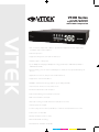
VT-EH Series 4, 8, and 16 Channel Digital Video Recorders with H.264 Compression VITEK • 4, 8, or 16 Video Inputs with 1 Main, 1 Spot Monitor Output and 1 DVI output (VGA compatible with included adaptor) • H.264 Compression • Supports both Dynamic and Static IP Addresses • 4 Alarm Inputs / 1 Relay Out • Up to 480fps Live Display & 480fps Recording (VT-EH16) / 240/240 (VT-EH8) / 240/240 (VT-EH4) • Remote Viewing over the Internet, LAN, Explorer, Safari, Firefox, Opera (Blackberry) & Chrome • Applications for iPhone, iPad, iTouch and Droid Devices • Supports two internal Hard Drives • 500GB to 4TB Internal Storage Options (up to 4TB @ 2x2TB) • “Quick Search” Function for automatic review • Email Event Notification with Snapshot • CMS Central Management Software (Included) • MAC Client Software (Included) • Automatic sending of Health and Event notifications via email • 4 Audio Inputs & 1 Output • Control locally via Front Panel, USB Mouse or with the Included IR Remote Control • PTZ Control over RS-485 • Backup via Ethernet, FTP or USB • Built-In Bandwidth Throttling • Rack Kit “Ears” Available (VT-E RK) CYAN MAGENTA YELLOW BLACK VT-EH Series DVRs________________________________________________________________________________ IMPORTANT SAFETY INSTRUCTIONS 1) Read these instructions. 2) Keep these instructions. 3) Heed all warnings. 4) Follow all instructions. 5) Do not use this apparatus near water. 6) Clean only with a dry cloth. 7) Do not block any of the ventilation openings. Install in accordance with the manufacturer's instructions. 8) Do not install near any heat sources such as radiators, heat registers, stoves, or other apparatus that produce heat. 9) Understand the safety purpose of a polarized or grounding type plug. A polarized plug has two blades with one wider than the other. A grounding type plug has two blades and a third grounding prong. The wide blade or the third prong is provided for your safety. When the provided plug does not fit into your outlet, consult an electrician for replacement of the obsolete outlet. 10) Protect the power cord from being walked on or pinched particularly at plugs, convenience receptacles, and the point where they exit from the apparatus. 11) Only use the attachments/accessories specified by the manufacturer. 12) Use only with a cart, stand, tripod, bracket, or table specified by the manufacturer, or sold with the apparatus. When a cart is used, use caution when moving the cart/apparatus combination to avoid injury from tip-over. 13) Unplug this apparatus during lightning storms or when unused for long periods of time. 14) Refer all servicing to qualified service personnel. Servicing is required when the apparatus has been damaged in any way including a damaged power supply cord or plug, if liquid has been spilled or objects have fallen into the apparatus, the apparatus has been exposed to rain or moisture, does not operate normally, or has been dropped. 15) This equipment is for indoor use and all the communication wirings are limited to use inside of the building. 16) The socket-outlet shall be installed near the equipment and shall be easily accessible. 17) CAUTION RISK OF EXPLOSION IF BATTERY IS REPLACED WITH AN INCORRECT TYPE. DISPOSE OF USED BATTERIES ACCORDING TO THE INSTRUCTIONS. # Operation Max temperature: 40ºC/104ºF # USB Load condition: USB Ports (5VDC, Max. 500 mA) 2 VT-EH Series DVRs________________________________________________________________________________ BEFORE INSTALLATION ● Installation should only be carried out by qualified personnel and in accordance with up-to-date electrical regulations. ● The DVR must be placed on a stable surface or mounted in an approved cabinet. Adequate ventilation must be provided, taking particular care not to block any of the air vents on the DVR. ● Adequate protection against lightning and power surges must be installed to prevent damage to the DVR. ● Any safety warnings on the DVR and in these instructions must be adhered to. ● If cleaning is necessary, shutdown the DVR and disconnect power first. Use only a soft, dry cloth and never use any abrasive cleaners. ● Do not attempt to service or repair the DVR as opening or removing covers may expose dangerous voltages or other hazards. Refer all servicing to qualified service personnel. 3 VT-EH Series DVRs________________________________________________________________________________ MAIN FEATURES MOUSE CONTROL Designed to be easily controlled with a mouse. ENHANCED GRAPHICAL USER INTERFACE [GUI] The DVR menu structure and on screen display is presented in a simple to use and logical GUI format. GENUINE PENTAPLEX OPERATION The DVR will continue to record at full frame rate during local playback, local setup, multi user remote viewing and playback and remote setup. AUDIO 4 audio inputs are supported which can be assigned to any video channel. Live and recorded audio can be monitored remotely over the internet and remote ‗talkback‘ audio transmission to the DVR is also possible. BACKUP Recorded footage (including audio) can be archived to a USB memory stick or to your computer through network connection. Playback software is embedded with the backup files. The backup also contains the system event log and backup log for full traceability. REMOTE CONNECTION Depending on the user level, full DVR control is available over the internet as well as the ability to remotely configure the DVR. Alarm outputs on the DVR can be remotely triggered over the internet. COMPREHENSIVE RECORDING SETUP Recording can be scheduled, alarm or motion activated. For each type of recording, frame rates, image quality and audio recording properties can be adjusted per hour, day and for each individual channel. The DVR also has a panic recording feature (from the front panel or external input) which overrides all other recording settings to provide the best quality recording in the event of an emergency. PTZ CONTROL Full PTZ control is available from the front panel or remote connection and a wide number of speed dome protocols are supported. Protocols can be set individually for each channel and PTZ speed can be adjusted to suit particular speed domes. 4 VT-EH Series DVRs________________________________________________________________________________ TELEMETRY CONTROL Full telemetry control is available from the front panel or remote connection and a wide number of speed dome protocols are supported. Protocols can be set individually for each channel and telemetry speed can be adjusted to suit particular speed domes. EXTENSIVE MONITOR SUPPORT The DVR has 2 main monitor outputs (Composite and DVI). One spot monitor output can be programmed in the DVR setup. LIVE DISPLAY The DVR displays single or multi screen images and also has several sequence modes (standard and user definable). CONFIGURATION BACKUP All configuration settings on the DVR can be saved to USB memory stick or a PC file remotely. The saved data can then be uploaded to other DVR units allowing rapid deployment where more than one DVR is being installed. EMAIL SUPPORT The DVR can send emails to specific users to notify events such as alarm, motion detection, hard drive failure, & etc. 5 VT-EH Series DVRs________________________________________________________________________________ SYSTEM ORGANIZATION 6 VT-EH Series DVRs________________________________________________________________________________ SYSTEM CONFIGURATION 1. Front panel description KEY DESCRIPTION Function Keys POWER Turns unit On/Off DISPLAY Selects various display modes in live display and playback SCR MODE Change display mode/Split mode SEARCH Displays the search menu MENU Displays the setup menus Control Keys CURSOR KEYS Navigates the menu system ENTER Apply settings or RETURN Cancel or go to Previous menu Select an item Playback Controls ◀◀ Increases reverse playback speed ◀ Selects reverse playback ΙΙ Pauses / resumes playback ▶ Selects forward playback and also accesses the instant playback feature ▶▶ Increases forward playback speed 2. Rear panel description 7 VT-EH Series DVRs________________________________________________________________________________ 1. CAMERA INPUTS Connect up to 16 camera inputs. 2. MAIN MONITOR / SPOT MONITOR OUTPUTS Connect AV monitor instead of VGA output / One spot monitor can be connected. 3. AUDIO INPUTS & OUTPUTS Up to 4 audio inputs and one audio output can be connected. 4. PAL/NTSC SWITCH 5. ALARM INPUTS & RELAY OUTPUT Up to 4 alarm inputs can be connected and configured as high or low inputs with common ground. One Relay output can be connected and configured as high or low with common ground Connection to external telemetry. 6. RS-485 – devices for PTZ or Keyboard controller 7. LAN - LAN connection to a router or internal network 8. DVI DVI main monitor connection to a PC monitor or plasma screen. Through DVI to VGA convertor, User can connect VGA port device as monitor. 9. DC POWER– connection 12V/5A adaptor 8 VT-EH Series DVRs________________________________________________________________________________ SYSTEM CONFIGURE – Remote Controller 3. Remote Controller description. POWER SETUP: Open System Setup Menu System ON/OFF Channel Selection Buttons ID Button AUDIO: Not Supported Select DVR ID ID ENTER: Apply / Select / Go to Next Screen RETURN Navigation Buttons: Cancel / Deselect Used for Playback Control, Menu Previous Screen Navigation, and PTZ/Focus Control DISP: Change display screen. SEARCH: Go to Search mode. PTZ: Go to PTZ menu. PANIC: Record by Panic setting. KEYLOCK: Lock the keys (Remote / Front) SEQUENCE: Change to Sequence screen. ZOOM: Go to Zoom mode. ARCHIVE: Go to backup menu. ※ If there are many DVRs on a stack, each DVR must be set with a different ID. You can do this here: Menu/System Setup/Main/System/Control Device. From the remote controller sync the remote to each DVR, then all DVRs can be controlled with one remote controller. How to sync a remote controller to a DVR’s ID Press the ID button on the remote. Notice REMOTE ID statement on the screen. On the remote controller, enter the System ID number, press ENTER, then press RETURN. (default System ID is 0) 9 VT-EH Series DVRs________________________________________________________________________________ CONNECT & POWER ON • Connect up to 16 CAMERA INPUTS as necessary. • Connect monitors to the DVR using the COMPOSITE or DVI connections. • Connect power to the DVR. The DVR checks for proper power connection and emits two beeps. Press the POWER BUTTON on the front panel of the DVR to begin operation. 1 Disk is Found Internal Disk Size: 244GB The DVR startup screen detects and checks the status of hard drive(s). External Disk Size: 0GB ……………………………………… After startup diagnostics are complete, the operator must logon to the system. The default user name is ‗ADMIN‘. Using the CHANNEL SELECTION buttons, key in the default password of ‗1234‘ and press the ENTER button. The DVR begins normal operation and shows the default display of all 4, 8 or16 channels depending on system model. The status bar (Include menu control) at the bottom of the screen shows menu first time. After that, it will show the current time and date. A title for each channel is shown. The red square and letter ‗C‘ in the top right of each channel display shows that the channel is recording in Continuous mode. 10 VT-EH Series DVRs________________________________________________________________________________ MENU CONTROL All menus can be controlled from the above ‗Status Bar‘ with the mouse or front buttons. LIVE DISPLAY DIVISION SCREEN Select the ‗DISPLAY‖ button for the screen division menu to appear. Select the screen type (1, 4, 6, 8, 9, 16 and rotation sequence). Sequence mode User can select the type from display menu. Press the SEQ button. Each channel is shown in full screen for a set period of time before switching to the next channel. To stop the sequence on a particular channel, press the SEQ button again. More complex sequences can be programmed through the setup menu. 11 VT-EH Series DVRs________________________________________________________________________________ LIVE DISPLAY 1) CAM: Select the Channel. 2) Preset: Input preset numbers 1~255. Click SET to save current view (camera position) as a preset. Click GOTO to move the camera to a saved preset position. 3) Zoom, Focus, IRIS: User can control each item with + or - button. 4) Parameter: Press this button and another window will appear. User can view each item from PTZ parameter menu. . (Parameter values can be set in CAMERA: PTZ SETUP) Digital Zoom Select the ―ZOOM‖ button. When viewing a channel in full screen, the operator can zoom in to a particular area by up to 8 times. To use the digital zoom, select the required channel and press the ZOOM button. The small window at bottom right shows the full image and the main display area shows the zoomed portion. Use ◀◀ and ▶▶keys to zoom in/out. 12 VT-EH Series DVRs________________________________________________________________________________ LIVE DISPLAY User can see the current log immediately. Click once after selecting log, recorded data will be played. This will appear if you select the ―PREVIEW‖ option. Panic Recording This menu is used to start and stop the Panic recording. If panic recording is started, the record icon will change to a red square with a ―P‖. Select once more to return to previous. - Panic recording setup will be assigned from Record menu. 13 VT-EH Series DVRs________________________________________________________________________________ LIVE DISPLAY Quick Menu User can use quick menu by right-clicking the mouse on each live channel. 1. Freeze On/Off: User can stop the live display of a channel that the user wants. Even though other channels show live display, this particular channel display is stopped. Click once more to return to previous. 2. PTZ Please refer to ―PTZ‖ menu on Page 12. 3. Zoom Please refer to ―ZOOM‖ menu on Page 12. 4. Playback User can playback immediately with selected time (10, 20, 30 seconds or 1 minute ago). In case of selecting ―go to‘‖ menu, this menu will appear. After selecting the time, press ―OK‖. 5. Record Start (Stop) Please refer to ―Panic record‖ menu on Page 13. 14 VT-EH Series DVRs________________________________________________________________________________ SYSTEM SETUP Click ―MENU‖ and click the SYSTEM SETUP menu. To navigate around any items in the setup menu, use the CURSOR KEYS and the ENTER and RETURN buttons. In general, the ENTER button is used to select and change a particular item and the RETURN button is used to cancel a change or exit from a particular setup screen. To setup all main system functions, highlight SYSTEM SETUP and press ENTER. 15 VT-EH Series DVRs________________________________________________________________________________ SYSTEM SETUP CAMERA Click the CAMERA menu. CAMERA: CAMERA SETUP To setup the various camera options, highlight CAMERA and press ENTER. TITLE: Input the camera title. COVERT: When it is set to ON, the camera image is not displayed in live display but continues to record. AUDIO: Determines the audio recording channel. CAMERA: COLOR SETUP Brightness, contrast, tint and color can be adjusted for each individual channel. Highlight each channel to modify and press ENTER. 16 VT-EH Series DVRs________________________________________________________________________________ SYSTEM SETUP Click each value with button. The selected channel is displayed in full screen. BRIGHTNESS, CONTRAST, TINT and COLOR can be changed as necessary. To modify a different channel, highlight CAMERA and choose the desired channel. Press RETURN when all changes are complete. CAMERA: PTZ SETUP Click the PTZ SETUP menu and click each value on the ADDRESS, PROTOCOL and BAUD RATE menu. Change each value with ADDRESS: The unique ID of the PTZ device. PROTOCOL: The protocol of the PTZ device. BAUD RATE: The baud rate of the PTZ device. DETAIL: Detail setting for PTZ device. (Refer to the next page) PRESET: Tour setting for PTZ device. (Refer to the next page) 17 button. VT-EH Series DVRs________________________________________________________________________________ SYSTEM SETUP Click the ―DETAIL‖ button and change the detail value with VITEK XPRESS button. Note that some settings, such as AUTO FOCUS, may not be compatible with particular PTZ equipment. If this is the case, changing the value will have no effect on PTZ control. Click the ―TOUR‖ button and set the MODE to [AUTO] to use TOUR function. First, please set PRESET number on the live PTZ mode. Then set the PRESET number from 1 to 16 and DWELL Time. DWELL TIME is the time spent in one position until you move to the next preset position. 18 VT-EH Series DVRs________________________________________________________________________________ SYSTEM SETUP CAMERA: MOTION SENSOR Click the MOTION SENSOR menu and click the value on the SENSITIVITY menu. Change the value with button. SENSITIVITY: Between 1 (Lowest) and 10 (Highest) and determines the degree of motion required before recording is activated. Click the AREA SETUP button. AREA SETUP: Choosing this option allows the operator to define which areas of the image are monitored for motion detection. To quick select or deselect the entire grid, click the right mouse button and click the SELECT ALL or DESELECT ALL menu. - Blank/clear area: Non selected area - White grid-like boxes: Selected area 19 VT-EH Series DVRs________________________________________________________________________________ SYSTEM SETUP DISPLAY To setup the various display options, highlight DISPLAY and press ENTER. DISPLAY - OSD Click the OSD menu. Then click the button for ON/OFF and change the value. STATUS BAR: Determines the time to turn from the menu of status bar to time display. CAMERA TITLE: Determines whether the camera title is displayed. RECORDING MODE ICON: Determines whether the DVR recording status is shown at the top right of each channel display window. BORDER: Determines whether there is a border around each channel in multi screen display mode. BORDER COLOR: If the border is ON, the operator can choose the color. MOTION SENSOR DISPLAY: If false motion recording is occurring, the operator can use this feature to determine and rectify the cause in real-time. OFF – normal display mode. ON – areas where motion is detected are highlighted with colored blocks. MOTION COLOR: The color of the blocks displayed when MOTION SENSOR DISPLAY is set to ON. LANGUAGE: Determines the language type. 20 VT-EH Series DVRs________________________________________________________________________________ SYSTEM SETUP DISPLAY: MONITOR Click the MONITOR menu Then click the button for ON/OFF and to change the value. SEQUENCE DWELL: The time each screen is displayed in a sequence operation. SPOT DWELL: The time each screen is displayed on the spot monitor outputs. DE-INTERLACE MODE: When recording any channels in D1 resolution (704 x 576), this should be set to ON to prevent shudder during playback. ALARM POP-UP MODE: When set to ON, an alarm input will cause the associated channel to display in full screen. ALARM POP-UP DWELL: Determines how long the full screen popup is displayed after an alarm input. If the alarm condition continues, the popup screen is displayed constantly. MOTION POP-UP MODE: When set to ON, motion detection will cause the associated channel to display full screen. MOTION POP-UP DWELL: Determines how long the full screen popup is displayed after motion detection. If motion continues, the popup screen is displayed constantly. 21 VT-EH Series DVRs________________________________________________________________________________ SYSTEM SETUP DISPLAY: SEQUENCE Click the SEQUENCE menu. When the SEQ button is pressed, the default sequence will cycle through all channels, one by one. Sequence setup allows the operator to define a custom sequence, using mixed multi screen views and any desired channels. Click the ADD menu. To add a new sequence, highlight ADD and press ENTER. Sequence title is highlighted – press ENTER to bring up the virtual keyboard and key in a name or reference number for the new sequence. Select the SAVE. Then, the menu below will appear. 22 VT-EH Series DVRs________________________________________________________________________________ SYSTEM SETUP Press ADD. Then, ―Sequence Setup‖ menu appears. Determine the ―VIEW TYPE‖ and assign ―CONFIGURE‖. Then, click CONFIRM. To add an additional mode, click ADD. After finishing the setup, press CLOSE. To modify the current one, double click that mode. Then ‗Sequence Setup‖ window will appear again. The new sequence is now saved and can be started by pressing the SEQ button when in live view. 23 VT-EH Series DVRs________________________________________________________________________________ SYSTEM SETUP DISPLAY: SPOT-OUT Click the SPOT-OUT menu and click the camera channel for ON/OFF. The DVR has 1 SPOT MONITOR OUTPUT. User can assign the SPOT OUT display for each channel. Double click the spot out channel that needs to be assigned. SPOT TITLE: input the title. ACTIVATION: Determines ON/OFF. Press MODIFY. (Below is default setup) To modify the current display, double click the display. Then ‗Spot Sequence Setup‖ window will appear. How to setup is the same as Sequence setup. (User can assign Single and Quad display only.) To add the additional display, press ADD. 24 VT-EH Series DVRs________________________________________________________________________________ SYSTEM SETUP SOUND Click the SOUND menu. To setup the various sound options, highlight SOUND and press ENTER SOUND: AUDIO Click the AUDIO menu and click the ON/OFF menu. Then, click the button for ON/OFF. LIVE AUDIO: When it is set to ON, the selected audio channel can be monitored on the AUDIO OUTPUT. AUDIO MONITORING CHANNEL: Specify which one of the 4 AUDIO INPUTS is routed to the AUDIO OUTPUT. NETWORK AUDIO TX: When set to ON, live and playback audio is transmitted to a remote PC connection. NETWORK AUDIO RX: When set to ON, allows a remote PC connection to send audio back to the DVR. SOUND: BUZZER Click the BUZZER menu and click the ON/OFF menu. Then, click the button for ON/OFF. KEYPAD: When it is set to ON, each front panel button press is confirmed by a beep. 25 VT-EH Series DVRs________________________________________________________________________________ SYSTEM SETUP SYSTEM Click the SYSTEM menu. To setup the various system options, highlight SYSTEM and press ENTER. DATE / TIME Click the DATE / TIME menu. DATE & TIME: Allows the operator to set or modify the current date & time. DATE FORMAT: Determines how the date is displayed. TIME FORMAT: Determines how the time is displayed. NETWORK TIME SERVER SETUP: If the DVR is connected to the Internet, the time and date can be accurately set by selecting SYNC and pressing ENTER. *User can modify default time server by double-clicking Network Time Server. TIME ZONE: It should be set according to the region the DVR is used in. D.S.T. (Daylight Savings Time): When it is set to ON, the DVR will automatically adjust the time by one hour on the relevant date in spring and autumn. 26 VT-EH Series DVRs________________________________________________________________________________ SYSTEM SETUP SYSTEM: SYSTEM MANAGEMENT Click the SYSTEM MANAGEMENT menu. SYSTEM INFORMATION: User can see the system information as below. F/W version: Shows the firmware version of the DVR. H/W version: Shows the hardware version of the DVR. VIDEO SIGNAL TYPE: The DVR automatically switches between PAL and NTSC depending on the channel 1 input signal at power on. DISK CAPACITY: Shows the total hard drive capacity installed. IP ADDRESS: Shows either the manual IP address entered in NETWORK setup or the IP address assigned by a DHCP server if enabled. MAC ADDRESS: Shows the MAC (Media Access Control) address of the DVR. It is unique – no other network device has this MAC address. DDNS DOMAIN NAME: If DDNS is enabled, the host DDNS server is specified here. RTSP SERVICE PORT: Real Time Streaming Port. This is the port the DVR uses to stream the video. WEB SERVER PORT: The port number that the DVR uses to support remote connection from Internet Explorer or other web browsers. 27 VT-EH Series DVRs________________________________________________________________________________ SYSTEM SETUP SYSTEM NAME: It is used so that notification emails can be identified. F/W UPGRADE: Firmware updates may be released periodically to enhance system performance and add extra features. The operator can upgrade the firmware using a USB memory stick. After inserting the F/W in USB, Press UPGRADE. Then the menu below will appear. After selecting the F/W from F/W list, press UPGRADE. FACTORY DEFAULT: This will set the unit back to factory settings. SYSTEM DATA: System settings can be saved to a USB memory stick. The settings can be reloaded in case of accidental factory reset or can be transferred to another DVR if multiple units need to be installed with the same settings. PASSWORD: Determines the PASSWORD ON/OFF to enter specific menu. SYSTEM: CONTROL DEVICE This will allow up to 254 DVRs to be controlled from the same keyboard. SYSTEM ID: If more than one DVR is connected on the same RS485 bus, each one must have a unique ID. Note: If using more than one DVR on stack, each DVR must have a unique ID for control by remote controller. PROTOCOL: Must be set by Control Device. BAUD RATE: Must be set to match the baud rate of the PTZ controller. 28 VT-EH Series DVRs________________________________________________________________________________ SYSTEM SETUP USER Click the USER menu. To setup the various system options, highlight USER and press ENTER. USER: USER MANAGEMENT By default, the DVR is configured with a user ID of ADMIN, belonging to the ADMIN group and with a password of 1234. As well as the ability to add new users, existing user details can be modified. To modify user details, highlight the user with the green cursor and press ENTER. The maximum number of users that can be created is 8. For editing, double click on the each tab. After changing, click OK. USER ID: Edit the user ID using the virtual keyboard. (Max. 10 characters) PASSWORD: Change the password using the virtual keyboard. (Max. 4 Characters) GROUP: Users can be assigned to one of three groups - ADMIN, MANAGER or USER. E-MAIL: Enter the user‘s email address if email notification is required. (Max. 64 Characters) E-MAIL NOTIFICATION: Enable or disable email notifications for the specified user. 29 VT-EH Series DVRs________________________________________________________________________________ SYSTEM SETUP USER ID: Edit the user ID using the virtual keyboard. PASSWORD: Change the password using the virtual keyboard. GROUP: Users can be assigned to one of three groups - ADMIN, MANAGER or USER. E-MAIL: Enter the user‘s email address if email notification is required. E-MAIL NOTIFICATION: Enable or disable email notifications for the specified user. USER: USER AUTHORITY User can give the authority to the MANAGER and USER. To select authority, click the APPLY button after selecting each item. Please note: Any user can be deleted except the default ADMIN user. USER: LOG OUT AUTO LOGOUT: Determines the AUTO LOGOUT ON/OFF. DURATION: AUTO LOGOUT ON determines the duration. 30 VT-EH Series DVRs________________________________________________________________________________ SYSTEM SETUP NETWORK Click the NETWORK menu and determine each value. NETWORK: IP SETUP Click the IP SETUP menu. DHCP: When enabled, the DVR will obtain an IP address automatically if it is connected to a DHCP server or router. WEB SERVICE: When enabled, it allows remote connections using Internet Explorer or other web browsers. IP ADDRESS: If DHCP is not being used, the IP address can be manually set. GATEWAY: If DHCP is not being used, the gateway IP address can be manually set. SUBNET MASK: If DHCP is not being used, the subnet mask can be manually set. 1ST DNS SERVER: If DHCP is not being used, the first DNS server can be manually set. 2ND DNS SERVER: If DHCP is not being used, the second DNS server can be manually set. RTSP SERVICE PORT: If the connected Router supports UP&P (Universal plug and play) function, clicking AUTO PORT will automatically complete the port forwarding. Clicking DELETE PORT will delete the port, and PORT TEST will test the ports. WEB SERVER PORT: If the connected Router supports UPNP (Universal plug and play), clicking AUTO PORT will automatically complete the port forwarding. Clicking DELETE PORT will delete the port, and PORT TEST will test the ports. The Web Server Port is also the port number that the DVR uses to support remote connection from Internet Explorer or other web browsers. ALIAS: When you enter the DDNS HOST NAME in DDNS setup (Next page), you can see the information here (only when connected to a UPNP router. MAX TX SPEED: Specifies the maximum bandwidth that the DVR can use during a remote connection. 31 VT-EH Series DVRs________________________________________________________________________________ HOW TO OBTAIN AN IP ADDRESS One of the easiest ways to obtain an IP address for your DVR is to use the built-in DHCP feature of your DVR. HOW TO SET UP DHCP The purpose of DHCP is to obtain all of the network information from the connected router. In most cases, the best way to do this is to cycle the DHCP feature which means turn it on, then off again. This will get the network information from the router, and then by turning DHCP off in the DVR, it will lock that address to the DVR. Using the DHCP Feature: 1) Go to your DVR‘s ‗main‘ menu, System SetupNetwork 2) ‗IP SETUP‘ should be selected by default. To the right, ‗DHCP‘ is listed. If it is ‗checked‘, uncheck it, then select ‗Apply‘ at the bottom of the screen. You should get a pop-up indicating the network is rebooting. (If DHCP was unchecked, see below) 3) Once the network reboots, go back and ‗check‘ DHCP and select Apply. Again, the network will reboot. 4) Make note of your DVR‘s IP address; you will need this for port forwarding. 5) Now, go back and ‗uncheck‘ DHCP; this will set your DVR‘s IP address to STATIC. If DHCP is ‘unchecked’, select it, then select ‗Apply‘ at the bottom of the screen. You should get a pop-up indicating the network is rebooting. Make note of your DVR‘s IP address; you will need this for port forwarding. Now, go back and ‗uncheck‘ DHCP; this will set your DVR‘s IP address to STATIC. 32 VT-EH Series DVRs________________________________________________________________________________ SYSTEM SETUP NETWORK: DDNS DDNS: When enabled, the DVR can be accessed through a Dynamic DNS server. Commonly used if a broadband connection does not have a static IP address. CAUTION To use the DDNS function, ports 8080 and 554 must be opened. (This is commonly known as port forwarding). a. Default WEB SERVER PORT: 8080 b. Default RTSP SERVICE PORT: 554 Default DDNS HOST NAME is set to the MAC (Media Access Control) address. Creating your DDNS Host Name The EH series allows you to actually name your DVR, and access it by that name. Steps 1) Access the DVR’s main menu by using the remote control, or by the buttons on the front of the unit 2) The Setup box will appear. Select “System Setup” 3) Select “Network” 4) Select “DDNS” 5) Make sure DDNS is turned “ON” 6) The user has the choice to use either the server provided by VITEK, Dvrlink.net, or an alternative server can be used— dyndns.org 33 VT-EH Series DVRs________________________________________________________________________________ DVRLINK.NET CONFIGURATION 1) Highlight DDNS Server, and change it to DVRLINK.NET 2) Highlight HOST NAME and press enter. The virtual keyboard will appear. Change the Host Name to your desired name by removing the previous entry--you can do this by repeatedly selecting the key. (When choosing your host name, please don’t include any spaces or special characters). Once you have entered your desired host name, select OK. 4) Select “TEST” under DDNS Registration to make sure the name is available. 5) Select ―TEST‖ under DDNS Connection to make sure you have a connection to the server. 6) Select APPLY at the bottom of the screen to apply your changes. 7) Bring up a browser (ex. Internet Explorer), and type: http://your-ddns-hostname.dvrlink.net:8080 in the address bar. For example: If your DDNS Host Name was Johndoesdvr, you would type: http://johndoesdvr.dvrlink.net:8080 NOTE: If you changed the webport, you will need to use that number, NOT 8080. DYNDNS.ORG CONFIGURATION Before configuring the DVR to use the dyndns.org server, you must first setup an account. Go to www.dyndns.com and create an account. If you have trouble creating an account, or need assistance please visit www.dyndns.com/support/. Setting up the DVR 1) Highlight DDNS Server and change it to DYNDNS.ORG. 2) Highlight HOST NAME and enter your dyndns hostname. 3) Highlight USERNAME and enter your dyndns username. 4) Highlight PASSWORD and enter your dyndns password. 5) Highlight DDNS REGISTRATION and select TEST. 6) Highlight DDNS CONNECTION and select TEST; This will test the DVR‘s connection to the server. 7) Select APPLY at the bottom of the screen. 34 VT-EH Series DVRs________________________________________________________________________________ SYSTEM SETUP REMOTE ACCESS You can remotely access your VT-EH series DVR in the following ways: 1. The DVR’s MAC address 2. The DVR’s DDNS Host Name (by default this is set to the MAC address) 3. Your external static IP address (if you have one) ******IMPORTANT****** In order to view your DVR remotely you must port forward BOTH the Web Server Port (the default is 8080) and the RTSP Service Port (the default is 554). If you need assistance with port forwarding, please reference your router’s manual or contact your Network Administrator/IT Professional. 1. MAC Address The MAC address is a unique identifier assigned to your DVR. By default, this address is listed as the DDNS Host Name. Here is how to find your DVR’s MAC address: 1. Access the DVR‘s main menu by using the remote control, or by using the buttons on the front of the unit. 2. The Setup box will appear. Select ―System Setup.‖ 3. Select ―System.‖ 4. Select ―System Management.‖ 5. Select ―System Information.‖ 6. The MAC address will be displayed here. 7. Bring up a browser (ex. Internet Explorer), and type: http://the-mac-address-of-your-dvr.dvrlink.net:8080 in the address bar. For example, if your MAC address was 001155555555, you would type: http://001155555555.dvrlink.net:8080. NOTE: If you changed the webport, you will need to use that number, NOT 8080. 35 VT-EH Series DVRs________________________________________________________________________________ SYSTEM SETUP REMOTE ACCESS 2. DDNS Host Name The EH series allows you to name your DVR, and access it by that name. Steps to name your DVR 1. Access the DVR‘s main menu by using the remote control, or by using the buttons on the front of the unit. 2. The Setup box will appear. Select ―System Setup.‖ 3. Select ―Network.‖ 4. Select ―DDNS.‖ 5. Make sure DDNS is turned ―ON.‖ 6. ―DDNS Host Name‖ –this is your host name. To create a new host name, please see pages 33-34 7. Bring up a browser (ex. Internet Explorer), and type: http://your-ddns-hostname.dvrlink.net:8080 in the address bar. For example, if your DDNS Host Name was Johndoesdvr, you would type: http://johndoesdvr.dvrlink.net:8080. NOTE: If you changed the webport, you will need to use that number, NOT 8080. 36 VT-EH Series DVRs________________________________________________________________________________ SYSTEM SETUP 3. IP Address If you have a STATIC IP ADDRESS, you can use this to access your DVR. Accessing the DVR REMOTELY To access the DVR remotely via IP address, use the WAN IP address of the network the DVR is connected to. (Sometimes this IP address is referred to as the LIVE, PUBLIC or OUTSIDE IP address) Steps: 1. Bring up a browser (ex. Internet Explorer), and type: http://your.static.ip.address:8080 in the address bar. For example, if your STATIC IP address was 10.10.10.10, you would type: http://10.10.10.10:8080 NOTE: if you changed the webport, you will need to use that number, NOT 8080. Accessing the DVR LOCALLY If you are on the same network as the DVR you will need to use the DVR‘s IP address to access it. Steps: 1. Access the DVR‘s main menu by using the remote control, or by using the buttons on the front of the unit. 2. The Setup box will appear. Select ―System Setup.‖ 3. Select ―Network.‖ 4. ―IP SETUP‖ should be selected by default. To the right, you should see the DVR‘s IP address. 5. Bring up a browser (ex. Internet Explorer), and type: http://your.DVR‘s.ip.address:8080 in the address bar. For example, if your DVR‘s IP address was 192.168.0.2, you would type: http://192.168.0.2:8080 NOTE: if you changed the webport, you will need to use that number, NOT 8080. If your DVR is behind a router, the IP address listed here will be a LOCAL address. You can only use this address to access the DVR locally. If your DVR is NOT behind a router, the IP address listed here should be your PUBLIC IP address. You can use this address to access your DVR from a remote location. 37 VT-EH Series DVRs________________________________________________________________________________ SYSTEM SETUP NETWORK: E-MAIL Click the E-MAIL menu. SERVER: The SMTP outbound email server that should be used to send email notifications. PORT: The outbound email port number. SECURITY: Set to OFF if the SERVER does not require a username and password to connect. USER: Enter your email account PASSWORD: If SECURITY is set to ON, enter the password here. FROM: Input the E-mail address or any text. It is only used for E-mail test (E-mail sender) TEST E-MAIL: User can test after inputting E-mail address to receiving test E-mail *Please contact your ISP, Email Provider, and/or Network Administrator if help is needed obtaining your email information. 38 VT-EH Series DVRs________________________________________________________________________________ SYSTEM SETUP EVENT / SENSOR Click the EVENT / SENSOR menu. To setup the various event handling options, highlight EVENT/SENSOR and press ENTER. EVENT / SENSOR: HDD EVENT Click the HDD EVENT menu. The DVR can monitor the hard drives and detect problems that may be developing. S.M.A.R.T. HDD ALARM: Enables SMART disk monitoring. CHECK INTERVAL: Can be adjusted as desired. DISK FULL EVENT: Determines ON/OFF. EVENT / SENSOR: ALARM INPUT Click the ALARM INPUT menu and click the OPERATION and TYPE values. OPERATION: Alarm inputs can be enabled or disabled. TYPE: Alarm inputs can be set as normally open or closed. TEXT: The text can be changed for each alarm input. 39 VT-EH Series DVRs________________________________________________________________________________ SYSTEM SETUP EVENT / SENSOR: ALARM OUTPUT Click the ALARM OUTPUT menu and click each value. Determines the behavior and actions that will trigger each of the 8/16 alarm outputs. Behavior settings ALARM OUT: Choose which alarm output to configure. OPERATION: The selected alarm output can be enabled or disabled. MODE: Can be either TRANSPARENT (the output is active only when the trigger criteria is present) or LATCHED (the output is active for a set period of time after a trigger). DURATION: In LATCHED mode, the time that the alarm output remains active after it has been triggered. TYPE: Can be set to high (0V to +5V when activated) or low (+5V to 0V when activated). HDD EVENT: Determines whether a hard drive event triggers the alarm output. Action settings ALARM: Determines whether alarm inputs will trigger the alarm output. VIDEO LOSS: Determines whether video loss on any of the selected channels will trigger the alarm output. MOTION: Determines whether motion detection on any of the selected channels will trigger the alarm output. Remember to select APPLY and press ENTER to save all settings before exiting these menus 40 VT-EH Series DVRs________________________________________________________________________________ SYSTEM SETUP EVENT / SENSOR: BUZZER OUT Click the BUZZER OUTPUT menu and click each value. Determines the behavior and actions that will trigger the internal buzzer. Behavior settings OPERATION: The internal buzzer can be enabled or disabled. HDD EVENT: Determines whether a hard drive event sounds the buzzer. MODE: Can be either TRANSPARENT (the buzzer sounds only when the trigger criteria is present) or LATCHED (the buzzer sounds for a set period of time after the trigger). DURATION: In LATCHED mode, the time that the buzzer sounds after it has been triggered. Action settings ALARM: Determines whether alarm inputs will sound the buzzer. VIDEO LOSS: Determines whether video loss on any of the selected channels will sound the buzzer. MOTION: Determines whether motion detection on any of the selected channels will sound the buzzer. Remember to select APPLY and press ENTER to save all settings before exiting these menus 41 VT-EH Series DVRs________________________________________________________________________________ SYSTEM SETUP EVENT / SENSOR: EMAIL NOTIFICATION Click the EMAIL NOTIFICATION menu and click each value. Determines the behavior and actions that will send an email to a remote user. Behavior settings NOTIFICATION: Email notification can be turned ON or OFF. SETUP CHANGE: Determines whether a setup change sends an email. HDD EVENT: Determines whether a hard drive event sends an email. BOOTING EVENT: Determines whether a booting event sends an email. SNAPSHOT NOTIFICATION: Determines whether an image (JPEG) of selected channel sends an email. Action settings ALARM: Determines whether alarm inputs will send an email. VIDEO LOSS: Determines whether video loss on any of the selected channels will send an email. MOTION: Determines whether motion detection on any of the selected channels will send an email. FREQUENCY: E-mail sending period (Max. 60 MIN) Email settings must also be configured in MAIL and USER MANAGEMENT from USER MANAGEMENT menu. 42 VT-EH Series DVRs________________________________________________________________________________ SYSTEM SETUP DISK MANAGE Click the DISK MANAGEMENT menu. To manage the internal hard drives, highlight DISK MANAGE and press ENTER. RECORD TIME LIMIT: In certain circumstances, it may be necessary to limit the amount of footage stored on the DVR (to comply with data protection laws for example). Recording can be limited to 12 hours, 1 day, 2 days, 3 days, 1 week or one month. Once the DVR has this amount of footage stored, it will start to overwrite the earliest recorded footage. OVERWRITE: When set to ON, the DVR will start overwriting the earliest recorded footage, once the hard drive becomes full. In this case, the percentage of hard drive used shown in live display will always be 99%. When it is set to OFF, the DVR will stop recording when the disk becomes full. FORMAT: If necessary, all footage can be erased from the DVR using this option. (You will not lose your DVR settings i.e. record settings, network settings, etc.). Please note: When a RECORD TIME LIMIT is set, the OVERWRITE option cannot be changed. 43 VT-EH Series DVRs________________________________________________________________________________ RECORD MENU RECORD MENU Click ―MENU‖. Input the password. Then main menu will appear. Click the RECORD SETUP menu. To setup the recording behavior of the DVR, highlight RECORD MENU and press ENTER. RECORD: RECORDING OPERATIONS Click the RECORDING OPERATION menu and click each value. Then, click the value with button to change. SCHEDULE MODE: Either DAILY (one schedule will apply to every day of the week) or WEEKLY (each day of the week has its own schedule). PRE EVENT RECORDING TIME: When the DVR is not in continuous recording mode, this setting determines the amount of time that is always recorded before an event occurs. (Motion detection, alarm input, etc). POST EVENT RECORDING TIME: When the DVR is not in continuous recording mode, this setting determines the amount of time that is always recorded after an event occurs. (Motion detection, alarm input, etc). DUAL STREAM: User can set 2 nd data stream for network data transmit. When user selects ‗Manual‘ for quality control, user can set quality for 2 44 nd stream also. VT-EH Series DVRs________________________________________________________________________________ RECORD MENU RECORD: CONTINUOUS/MOTION Click the CONTINUOUS/MOTION SETUP menu. This setup screen allows the operator to configure scheduled and motion detection recording. There are 2 sections: SIZE/FPS/QUALITY: Recording settings for each channel can be defined across a 24 hour period, in blocks (for example between 09:00 and 18:00) or for each individual hour. Note that when SCHEDULE MODE is set to WEEKLY, each day of the week can also be selected. ACTIVATION: This section determines at what times the DVR will record and whether it is in continuous recording or motion detection. SIZE/FPS/QUALITY Click the SIZE/FPS/QUALITY menu. To change the SIZE/FPS/QUALITY, highlight CONTINUOUS/MOTION SETUP and press ENTER. Ensure the SIZE/FPS/QUALITY is highlighted in yellow and press ENTER again. The 24 hour time bar is highlighted in green. 45 VT-EH Series DVRs________________________________________________________________________________ RECORD MENU Click the TIME BAR that user wants to have the values changed. Press ENTER to display the green cursor. The green cursor shown represents one hour. The table below the time bar shows the recording settings for this time period. Drag the time that user wants to have the values changed. Example: To change the recording settings between 09:00 and 18:00. Use the CURSOR KEYS to move the green cursor to the 09:00 position and press ENTER. The cursor changes to orange to show the start position. Use the CURSOR KEYS to stretch the orange cursor across to the 18:00 position. 46 VT-EH Series DVRs________________________________________________________________________________ RECORD MENU Click the SIZE, FPS, QUALITY and AUDIO value. Then click the value with button to change. Press ENTER. Recording settings for the selected time period are displayed. SIZE: Recording resolutions of 352x240 (CIF), 704x240 (2CIF) or 704x480 (D1) NTSC can be selected for each channel. FPS: Frame rates between 1 and 30 can be set for each channel. QUALITY: Five different picture recording qualities can be set for each channel. (Low/Standard/High/Highest/Super) AUDIO: If audio devices are connected to the DVR, user can select the audio recording on/off. Any audio channel can be assigned to any of the video channels. Please refer to camera setup menu. nd 2 FPS: Determines network transmit frame independent from recording. This field will be available when you select dual stream ‗ON‘. nd 2 QUALITY: Determines network transmit quality independent from recording. This field will be available when you select DUAL STRREAM QUALTY CONTROL as ‗MAUAL.‘ During playback, when a particular channel is selected in full screen, the assigned audio channel will be played back at the same time. Adjust values as desired and select OK to finish and return to the parameter menu. Other time periods can be configured in the same manner. Note: When you activate the dual stream, the DVR divides the available recording frame rate as Recording and Network. (VT-EH16 - 480 FPS DVR will be divided as 240fps for recording and 240 fps for network) Remember that if SCHEDULE MODE is set to WEEKLY, recording settings needs to be changed for each day as well as for each particular time. Note: The VT-EH16 DVR supports a maximum recording rate across all channels of 480 frames per second at 352x240 resolution. As settings are adjusted, the ‘frames available’ at the bottom left displays the number of available frames still remaining and must always be zero or higher. If, while changing recording settings, this figure becomes negative, recording resolutions and / or frame rates must be lowered to increase the ‘frames available’ value to zero or above. 47 VT-EH Series DVRs________________________________________________________________________________ RECORD MENU ACTIVATION Click the ACTIVATION menu. To change ACTIVATION settings, highlight CONTINUOUS/MOTION RECORDING and press ENTER. Use the CURSOR KEYS to highlight ACTIVATION and press ENTER. The schedule box is highlighted in green. Drag the Time and Channel with left mouse click. After selecting the area, determines the recording type. The schedule screen has 4 symbols to show the different recording modes. NO COLOR blocks: No scheduled or motion recording. SKY BLUE blocks: The DVR will record continuously. BLUE block: The DVR will only record while motion is detected. PINK block: The DVR will record continuously and with motion event. 48 VT-EH Series DVRs________________________________________________________________________________ RECORD MENU RECORD: ALARM SETUP Click the ALARM RECORDING menu. The setup is the same as CONTINUOUS/MOTION RECORDING. This setup screen allows the operator to configure alarm input activated recording. SIZE/FPS/QUALITY: Recording settings for each channel can be defined across a 24 hour period, in blocks (for example between 09:00 and 18:00) or for each individual hour. Note that when SCHEDULE MODE is set to WEEKLY, each day of the week can also be selected. ACTIVATION: This section determines at what times the DVR will monitor the alarm inputs and activate recording. Please refer to Continuous / Motion setup for setting up SIZE/FPS/QUALITY and ACTIVATION. Alarm activated recording can be used in conjunction with Continuous / Motion Recording. For example, the DVR could be configured to record continuously at a low frame rate (set in Continuous / Motion Recording) and then increase to a higher frame rate during an alarm input (set in alarm setup). 49 VT-EH Series DVRs________________________________________________________________________________ RECORD MENU RECORD: PANIC SETUP Click the PANIC RECORDING menu. Select the Size, Frame, Quality and Audio. During panic recording mode, the DVR will override all other recording settings and record continuously on all channels at the settings configured here. 50 VT-EH Series DVRs________________________________________________________________________________ SEARCH SEARCH To search for a particular section of recorded footage, press the SEARCH button. To protect unauthorized viewing of footage, only ADMIN and MANAGER user levels can playback footage. To login as ADMIN, enter the default password of 1234 and press ENTER. SEARCH: TIME SEARCH Click the date that user wants to have the values changed. The DVR uses a calendar and timeline search method for quick access to recorded footage. The calendar displayed on the left shows the current month. Days highlighted in yellow have recorded footage. The timeline on the right shows a 24 hour status of all channels for the selected day. The recorded time will be displayed with different color on each recording type. Panic: White Motion: Green Timer: Sky blue Alarm: Red 51 VT-EH Series DVRs________________________________________________________________________________ Drag the time bar with left mouse click. Press ENTER to select the calendar and use the CURSOR KEYS to move to the required day. As different days are selected, the timeline display also changes to show recorded footage on that day. Press ENTER to choose the day and move to the timeline. Click the PANO (Thumbnail mode) PLAY (Multi View) buttons Use the CURSOR KEYS to move the timeline cursor left or right to select the time segment required. The currently selected time is displayed under the calendar. Press PLAY to begin playback from the selected time. 52 VT-EH Series DVRs________________________________________________________________________________ SEARCH MODE: PANO PANO (Thumb nail): Each Screen shows 3 hour data. CH1: 0~3 O‘clock CH2: 3~6 O‘clock CH8: 21~24 O‘clock User can select different channels and playback with faster speed of up to x64. SEARCH MODE: Multi Playback PLAY (Multi view): The default playback mode is of a 16 screen display. By pressing DISPLAY or using the CHANNEL SELECTION buttons, it is possible to display a single screen or other multi screen formats in a similar way to the live display mode. During playback, user can reserve the recorded data that needs to be archived. Press button at the time the archive is to be started. Then playback is stopped and the menu below will appear. After inputting ―TAG‖ name, press START. Then display is returned to playback. Press button again to end archiving. Then menu below will appear again. 53 VT-EH Series DVRs________________________________________________________________________________ RESERVE: Press this to reserve current data. CONTINUE: Press this to reserve more data. Then display will return to playback. STOP: Make sure to press this button to reserve current data first. Then user can select RESERVE. START: Press this to start the reserve. CLOSE: Finish archiving. Reserved data will be reserved on HDD. User can see the reserved data from ―RESERVED DATA MANAGEMENT‖ on ARCHIVING menu To exit playback mode and return to the search screen to choose another time and date, press RETURN. To exit the search screen and go back to live view, repeatedly press RETURN. 54 VT-EH Series DVRs________________________________________________________________________________ SEARCH: EVENT SEARCH The DVR event log stores events such as motion and alarm activated recording, video loss, etc. To search for an event and playback the recorded footage, press the SEARCH button and log in as ADMIN with the default password of 1234. Click the SEARCH BY EVENT menu and select each desired channel and condition. Then click the time with button to change. Click the SEARCH button. Playback footage for a particular event, select the event from the list using the CURSOR KEYS and press ENTER. 55 VT-EH Series DVRs________________________________________________________________________________ Playback resumes from the moment when the selected event occurred and continues until stopped by the operator. During event search playback, the playback buttons can be used as normal. To stop playback and return to live view mode, repeatedly press RETURN. ARCHIVING NEW ARCHIVING To archive recorded footage to a USB memory stick, press the ARCHIVE button. To protect unauthorized viewing and distribution of footage, only the ADMIN user level can archive footage. To login as ADMIN, enter the default password of 1234 and press ENTER. Click each desired channel. Then click the times with button to change. Click the QUERY menu. Make sure to press QUERY first before selecting BURN or RESERVE. Press RELEASE to reset after QUERY. RESERVE: Press this after inputting the TAG name. OR BURN: Press this after inputting the TAG name. Then press START after the menu below appears. 56 VT-EH Series DVRs________________________________________________________________________________ RESERVED DATA MANAGEMENT AVI ARCHIVING LIST: User can see the AVI archiving data that was reserved from new archiving menu or archiving of search. INFORMATION: The detailed information of Reserved AVI data. DELETE: User can delete the reserved AVI data BURN: Backup the selected AVI data. 57 VT-EH Series DVRs________________________________________________________________________________ FTP SETUP FTP Archiving is possible. User must set up the Host Name, Port number, User Name, and Password with the FTP server. FTP Archiving is possible on New Archiving or Reserved Data Management. DIRECTORY – Archived data will be saved to this user-defined folder on your FTP site. FTP TEST – Tests connectivity to the FTP server. WEB CONNECTION SETUP PRELIMINARY BEFORE CONNECT For connecting over the web (also known as Remote Viewing), ports 554 and 8080 need to be port forwarded in the router. Refer the manual of Router for port forwarding setting WEB RA MINIMUM PC REQUIREMENT CPU P4 3.0 or Higher RAM 512MB or Higher Geforce MS 400, Radeon 7500 or higher VGA Geforce 8 series or higher VGA MEMORY 64MB MONITOR 1280X1024 OS WINDOW XP2 IE VERSION IE6.0 or higher NETWORK 100Mbps DIRECT X V7.0 or higher 58 VT-EH Series DVRs________________________________________________________________________________ HOW TO CONNECT Input the IP Address or URL of the DVR in the Internet Explorer Address Bar. See pages 35-37 for more details. Default ID and password are ‗ADMIN‘ &‘1234‘ User needs to install Active-X, click Run Add-on Windows Internet Explorer In case user is unable to install active-X, User needs to check the option of activeX on IE security menu. 59 VT-EH Series DVRs________________________________________________________________________________ Select Enable for all ActiveX related options. (Ex: Download signed ActiveX control, Download unsigned ActiveX control….) LIVE MODE 60 VT-EH Series DVRs________________________________________________________________________________ Explanation for function LIVE mode Select live division screen (1, 4, 8,9,16 split mode) Sequence mode Move to next camera Full screen Select live channel. – select a channel manually. Activate Mic to send a sound to DVR On/Off Sound from DVR Save the live image Print the current screen Snapshot the current screen Setup [Render] and [Save Folder] • Status: Show active status of DVR 1. Alarm – Indicator will be marked when system detects Alarm input 2. Motion- Indicator will be marked when system detects Motion 3. Video Loss - Indicator will be marked when system detects Video Loss 4. Recording – Display current recording mode Continuous Motion Panic Alarm Stand By 5. Alarm Out - Indicator will be marked when system detect Alarm output 6. Refresh Time – set interval of refresh or Reload for manual refresh 61 VT-EH Series DVRs________________________________________________________________________________ • Log : Display all system logs with real time • PTZ: User is able to control connected PTZ camera. 1. Pattern – move a camera among several preset positions 2. Preset – set a position of camera view 3. Swing – move a camera between two preset points 62 VT-EH Series DVRs________________________________________________________________________________ SEARCH (By time line) 1. Select a time line on time table or set an exact time. 2. Then press ‗Play‘ button 1. Refresh: Refresh the recording table of data. 2. Play: Start to display the recorded data from system. 3. Backup: User can back up the recorded data on remote site. 63 VT-EH Series DVRs________________________________________________________________________________ Backup 1. Select the desired Start and End Time 2. Select the desired channel(s) 3. Click Start. By default, the video will be saved to the C:\SaveFolder SEARCH (By Event) 1. Event: Select events for querying. 2. Period: Set duration for querying recording data. 3. Search: Start to query and list up all events on the list. 4. Select an event on the list then the DVR will start to playback the related camera‘s image 64 VT-EH Series DVRs________________________________________________________________________________ SETUP MODE 1. CAMERA User can configure camera‘s attribute such as title, live color, PTZ setup or motion. Motion setup for detecting motion events. 1) Select Motion menu tab. 2) Select a channel and sensitivity. 3) Drag a mouse on the image to select detecting area. 4) Press OK. 65 VT-EH Series DVRs________________________________________________________________________________ 2. Display 1) OSD –Choose text to display over the image. 2) Monitor - User can set dwell time for sequence or spot, and pop up function. 66 VT-EH Series DVRs________________________________________________________________________________ 3. Sound 1) Audio Setting – Select a live audio channel and activation 2) Buzzer setting – Activate buzzer out for event notification 4. System User can configure the DATE of the system. Check system information and set controller. 67 VT-EH Series DVRs________________________________________________________________________________ 5. Recording User can configure the recording parameter. Setting detail is same as system. 6. User To add a User, select Add, then assign Authority level and Log Out time. 68 VT-EH Series DVRs________________________________________________________________________________ 7. Network User can check the system‘s network information and selectable speed level. IP settings are not allowed to be changed on remote site. Network IP can only be changed from DVR. For email notification, user can input the SMTP server detail as shown below. 69 VT-EH Series DVRs________________________________________________________________________________ 8. Sensor Management can set all device option of Alarm in/out, Buzzer out for event notification. (HDD EVENT, Alarm Input, Alarm output, Buzzer out, E-mail notification option) All detail setup follow DVR system setup INFORMATION Display Model name of DVR and WEB Remote Software version. 70 VT-EH Series DVRs________________________________________________________________________________ BACKUP PLAYER To view archives backed up from a DVR, double click BackupPlayer (located in the Player folder). NOTE: When archiving from the web browser to a PC, the BackupPlayer is NOT included. To obtain the BackupPlayer, user must physically archive from the DVR to a USB flash drive. Click to choose which archive file to playback. Playback of the archive file begins. The controls under the display can be used to adjust playback direction and speed. WATERMARK PROCESS 1. Run ―BackupPlayer‖ then select the desired archived media. 71 VT-EH Series DVRs________________________________________________________________________________ 2. Click the [Open file] button and open the backup file. 3. After opening file, select ―Yes‖ to check the watermark. 4. If the backuped AVI file is modified, [Verification failed] message will appear. 72 VT-EH Series DVRs________________________________________________________________________________ SMARTPHONE CONNECTION iPHONE 1. Select the Safari browser. 2. Enter the IP address or URL to connect. And Click the [GO] button. 3. Enter the User name and Password then use can see the Image. (Default: ADMIN / 1234) 73 VT-EH Series DVRs________________________________________________________________________________ BlackBerry 1. Select the Web browser. 2. Enter the IP address or URL to connect. And press the Enter button. 3. Enter the User name and Password then use can see the Image. (Default: ADMIN / 1234) 74 VT-EH Series DVRs________________________________________________________________________________ ‘DVR Viewer’ Guide (iPhone / iPad / Android) 1.1 – Install & Connect (iPhone & iPad) 5. Insert IP and ports then save 1. Search and Install ―Vitek DVR Viewer‖ in Apple APPstore 6. Insert ID, Password and login type select (Default: Auto Login) then save ADMIN 2. Run ‗DVR Viewer‘ Application **** 3. ADD Connection List 7. Select DVR in list 4. Server Name This is just a way to differentiate between multiple DVR‘s in the list. Please name your DVR 8. View CAMERA live video anything you like, then Save. DVR1 75 VT-EH Series DVRs________________________________________________________________________________ 1.2 – Install & Connect (Android) 1. Search and Install ―Vitek EH DVR Viewer‖ in 4. Insert name, URL, ports, ID, Password and select ID/Password save type then select ‗Save‘ button Android market **** -> 2. Run ‗Vitek EH DVR Viewer‘ Application 5. Long press DVR in list then select Connect button -> 3. ADD Connection List (Select menu button) -> 76 VT-EH Series DVRs________________________________________________________________________________ 2 – PTZ & Snapshot (PRO version) 3 – Log View (PRO version) 1. Touch the ‗PTZ‘ button 1. Touch the ‗log view‘ button 2. Set PTZ by pressing ‗+/-/∧/∨/</>‘ button. 2. Select start/end time and Filter Option select after touch ‗search‘ button 3. Set Image Capture By using ‗camera‘ Button. 3. View the log list 77 VT-EH Series DVRs________________________________________________________________________________ 4 – Search (PRO version) 5 – Setup (PRO version) 1. Touch the ‗Search‘ button 1. Touch the ‗Setup‘ button 2. Select date/time and touch play button 2. WebRA setup menu and the same settings are available. 3. User can do the playback, rewind, fast-forward and Split Screen Search. 78 VITEK LIMITED PRODUCT WARRANTY VITEK products carry a limited three (3) year manufacturer’s warranty with the exception of hard drives which carry a five (5) year direct factory* warranty. VITEK warrants to the purchaser that products manufactured by VITEK are free of any rightful claim of infringement or the like, and when used in the manner intended, will be free of defects in materials and workmanship for a period of three (3) years, or as otherwise stated above, from the date of purchase by the end user. This warranty is nontransferable and extends only to the original buyer or end user customer of a VITEK Authorized Reseller. The product must have been used only for its intended purpose, and not been subjected to damage by misuse, willful or accidental damage, caused by excessive voltage or lightning. The product must not have been tampered with in any way or the guarantee will be considered null and void. This guarantee does not affect your statutory rights. Contact your local VITEK Reseller should servicing become necessary. VITEK makes no warranty or guarantee whatsoever with respect to products sold or purchased through unauthorized sales channels. Warranty support is available only if product is purchased through a VITEK Authorized Reseller. Visit www.vitekcctv.com to register your product warranty and receive periodic updates. *HDDs warranted for five (5) years from the hard drive manufacturer directly. You may contact VITEK directly for additional assistance with the return of Hard Drives to the original manufacturer. 28492 CONSTELLATION ROAD VALENCIA, CA 91355 WWW.VITEKCCTV.COM | 888-VITEK-70