1
DSP4 HEADS UP DISPLAY
INSTRUCTION MANUAL
REVISION: 2/99
COPYRIGHT (c) 1984-1999 CAMPBELL SCIENTIFIC, INC.
WARRANTY AND ASSISTANCE
The DSP4 HEADS-UP DISPLAY is warranted by CAMPBELL SCIENTIFIC, INC. to be free from defects
in materials and workmanship under normal use and service for twelve (12) months from date of shipment
unless specified otherwise. Batteries have no warranty. CAMPBELL SCIENTIFIC, INC.'s obligation under
this warranty is limited to repairing or replacing (at CAMPBELL SCIENTIFIC, INC.'s option) defective
products. The customer shall assume all costs of removing, reinstalling, and shipping defective products
to CAMPBELL SCIENTIFIC, INC. CAMPBELL SCIENTIFIC, INC. will return such products by surface
carrier prepaid. This warranty shall not apply to any CAMPBELL SCIENTIFIC, INC. products which have
been subjected to modification, misuse, neglect, accidents of nature, or shipping damage. This warranty
is in lieu of all other warranties, expressed or implied, including warranties of merchantability or fitness for
a particular purpose. CAMPBELL SCIENTIFIC, INC. is not liable for special, indirect, incidental, or
consequential damages.
Products may not be returned without prior authorization. To obtain a Returned Materials Authorization
(RMA), contact CAMPBELL SCIENTIFIC, INC., phone (435) 753-2342. After an applications engineer
determines the nature of the problem, an RMA number will be issued. Please write this number clearly on
the outside of the shipping container. CAMPBELL SCIENTIFIC's shipping address is:
CAMPBELL SCIENTIFIC, INC.
RMA#_____
815 West 1800 North
Logan, Utah 84321-1784
CAMPBELL SCIENTIFIC, INC. does not accept collect calls.
Non-warranty products returned for repair should be accompanied by a purchase order to cover the repair.
815 W. 1800 N.
Logan, UT 84321-1784
USA
Phone (435) 753-2342
FAX (435) 750-9540
www.campbellsci.com
Campbell Scientific Canada Corp.
11564 -149th Street
Edmonton, Alberta T5M 1W7
CANADA
Phone (403) 454-2505
FAX (403) 454-2655
Campbell Scientific Ltd.
Campbell Park
80 Hathern Road
Shepshed, Leics. LE12 9RP
ENGLAND
Phone (44)-50960-1141
FAX (44)-50960-1091
DSP4 HEADS UP DISPLAY
TABLE OF CONTENTS
PAGE
WARRANTY AND ASSISTANCE
1.
1.1
1.2
1.3
1.4
2.
2.1
2.2
2.3
3.
3.1
3.2
3.3
3.4
3.5
3.6
3.7
3.8
3.9
3.10
INTRODUCTION
Specifications ............................................................................................................................ 1
Product Terminology ................................................................................................................. 1
Overview.................................................................................................................................... 1
Summary of Features................................................................................................................ 1
PREPARATION
Installation ................................................................................................................................. 2
Hardware Connections with SM192/SM716/CSM1................................................................... 2
System Power-up ...................................................................................................................... 2
OPERATION
The Command Mode................................................................................................................. 2
Displaying Datalogger Input Locations (RUN MODE) ............................................................... 2
Controlling Datalogger Flags with the DSP4 ............................................................................. 3
Programming the Datalogger .................................................................................................... 3
From a Remote Communications Link...................................................................................... 4
Saving a Datalogger Program (SAVE MODE) .......................................................................... 4
Creating/Editing Input Location Labels (LABEL MODE) ........................................................... 4
Communication Via a Modem ................................................................................................... 4
Controlling Data Output to Peripherals (PRINTER MODE)....................................................... 5
DSP4 Reset and Memory Backup............................................................................................. 6
APPENDIX
A.
A.1
A.2
A.3
CHANGING PROM OR RAM CHIPS
Disassembly of the DSP4.......................................................................................................A-1
Installing New PROM Chips ...................................................................................................A-1
Installing New RAM Chips ......................................................................................................A-1
FIGURES
1.2.1
A-1
DSP4 Heads Up Display............................................................................................................ 1
Memory Sockets on the CPU Card ........................................................................................A-1
DSP4 HEADS UP DISPLAY
1.4 SUMMARY OF FEATURES
1. INTRODUCTION
1.1 SPECIFICATIONS
•
Power Requirement: 10.0 to 15.6 VDC at 1
AMP
- Locations shown are changed with scroll
UP and DOWN keys.
Operating Range: -40 to +80°C standard
Dimensions:
2.9" x 12.9" x 3.3"
•
Displays the datalogger real time clock as
input location 0.
•
Allows datalogger flags 1 through 8 to be
set via keys on the DSP4.
•
Reads datalogger programs and labels
from a Storage Module, CSM1, or with
direct connection to a PC using an SC32A
interface. Cassette tape is no longer
supported after January 1, 1998.
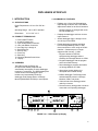
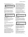
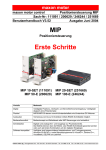
1.2 PRODUCT TERMINOLOGY
1. Power ON/OFF switch
2. 12 Volt DC power plug
3. 9-Pin female Ribbon Connector
4. 9 Pin male Ribbon Connector
5. User Flag Key 1 through 8
6. Scroll Down Key
7. Scroll Up Key
8. Cursor Key
9. Select Key
10. Mounting Bracket Screw Holes
11. Display
Displays any 4 of the first 254 datalogger
Input Storage Locations with a 9 character
alphanumeric label for the first 99 locations.
- Program retained in DSP4 for
reprogramming datalogger without
rereading from Storage Module or CSM1.
• Programs datalogger with the program
stored in its RAM memory.
1.3 OVERVIEW
The DSP4 Heads Up Display is a
microprocessor-based peripheral that
automatically interrogates an active datalogger
to which it is connected. The DSP4 displays the
current values of the datalogger's input
locations and automatically sends any
datalogger Final Storage data to a Storage
Module (SM192/SM716/CSM1) or serial printer.
• Stores datalogger programs and labels
on Storage Modules or CSM1.
• Allows input location labels to be
developed and/or edited directly.
• Buffers datalogger Final Storage data
and automatically writes it to Storage
Modules, CSM1, and printer.
• Yields access to the datalogger when
called by a modem.
• Protects memory during power loss when
connected to an operating datalogger.
FIGURE 1.2.1. DSP4 Heads Up Display
1
DSP4 HEADS UP DISPLAY
2. PREPARATION
2.1 INSTALLATION
When installing the DSP4, use the 1/4x20x1/3"
mounting bracket screw holes on both side
panels (Figure 1.2.1 Item 11). Velcro is also
used in many applications to mount and secure
the unit. In direct sunlight, a sun shield or visor
may be used to reduce glare.
2.2 HARDWARE CONNECTIONS WITH
SM192/SM716/CSM1
1. Connect an external 1 Amp 12 VDC power
supply to the DSP4 "DC IN 12V" connector.
2. Turn on the DSP4 power switch.
3. Connect the DSP4 male 9 pin ("TO
DATALOGGER") connector cable to the
datalogger.
4. Connect the DSP4 female 9 pin ("TO
PERIPHERALS") connector cable to the
SM192/SM716, CSM1, or PC via a modem
(e.g. SC32A, COM200).
the message "DATALOGGER BUSY." As soon
as the datalogger completes the peripheral
function the DSP4 automatically establishes
and maintains communication. If for some
reason the communication is broken with a
properly connected datalogger, the DSP4 will
automatically re-establish communication.
3. OPERATION
3.1 THE COMMAND MODE
When an operating datalogger is connected, the
DSP4 establishes communication and enters
the COMMAND mode. One of the seven
following modes can then be selected using the
CURSOR key to position the cursor at the
desired mode and the SELECT key to enter the
mode.
RUN
Display Datalogger Input
Locations with User Assigned
Labels created with the DSP4 or
transferred to the DSP4.
LOAD
Load Datalogger Program with
Labels from Storage Module or
CSM1 to DSP4's RAM memory
and simultaneously send the
program to the datalogger.
SAVE
Save the Datalogger Program
with the current labels to a
Storage Module or CSM1.
PROGRAM
Program Datalogger with the
Program Stored in the DSP4's
RAM Memory.
LABELS
Create/Edit Labels assigned to
the Datalogger Input Locations.
EXIT
Exit Telecommunications with the
Datalogger and enable the
datalogger keyboard.
PRINTER
Enable Printer Output and Set
Baud Rate.
2.3 SYSTEM POWER-UP
2.3.1 POWER-UP SELF TEST
When power is applied to the DSP4, it displays
the message "DSP4 DISPLAY" and automatically
tests its memory. If the DSP4 passes the self
test, it immediately attempts to establish
communications with the datalogger. If an error
is encountered during this memory test, the DSP4
displays one of the following messages to
indicate the defective memory area:
"PROM 0 ERROR"
"PROM 1 ERROR"
"RAM ERROR"
2.3.2 ESTABLISHING COMMUNICATIONS
WITH THE DATALOGGER
If a datalogger is not connected to the DSP4, or
if the datalogger is not on, the DSP4 will display
the message "DATALOGGER NOT READY."
Once a powered datalogger is connected or reconnected, the DSP4 establishes
communications automatically. If
communication cannot be established because
the datalogger is servicing a peripheral (Storage
Module, CSM1, or printer), the DSP4 displays
2
3.2 DISPLAYING DATALOGGER INPUT
LOCATIONS (RUN MODE)
3.2.1 CHANGING THE INPUT LOCATIONS
DISPLAYED
Use the CURSOR key to position the cursor
under one of the four location numbers shown
on the display. Use the UP or DOWN key to
change the datalogger location displayed.
DSP4 HEADS UP DISPLAY
Momentarily pressing the UP or DOWN key
causes a single location change.
With the cursor under the colon in the first
quadrant, pressing the UP or DOWN keys
causes all four displayed locations to change by
one location.
The DSP4 retrieves Final Storage data
regardless of the Instruction 96 or *4 options
selected in the datalogger. Because the DSP4
maintains continuous telecommunications with
the datalogger, the datalogger does not have
the opportunity to send data directly to the
Storage Module. Final Storage data sent to the
DSP4 also remains stored in the datalogger. If
a Storage Module, CSM1, or printer is not
connected to the DSP4, the data can be
retrieved from the datalogger when the DSP4 is
disconnected from the datalogger.
With the cursor under the colon in the forth
quadrant, pressing the UP or DOWN key
changes all four displayed locations by four
locations (e.g., if locations 1, 2, 3, and 4 were
displayed, pressing UP would display 5, 6, 7,
and 8).
In summary, Final Storage data can be stored
on Storage Module, CSM1, or printer by
connecting these devices to the DSP4 or by
connecting these devices to the datalogger after
test completion when the DSP4 is disconnected
from the datalogger.
NOTE: If either key is pushed for longer
than 1/3 of a second, the locations scroll at
a rapid rate.
NOTE: If you try to view input locations with
higher numbers than allocated in the
datalogger *A Mode, E09 will be displayed
on the datalogger.
3.2.2 STORAGE MODULE OR CSM1
PREPARATION
When communication is established with the
datalogger and the RUN mode is selected, the
DSP4 prompts the operator to prepare the
media used for recording data.
NOTE: A file mark may not be sent to a
Storage Module or CSM1 while using a
DSP4.
3.3 CONTROLLING DATALOGGER FLAGS
WITH THE DSP4
The datalogger user flags are alterable by
pressing the user flags keys on the DSP4 front
panel in the RUN mode. When a flag is high in
the datalogger, the LED associated with that
flag is on. When a flag is low in the datalogger,
the LED is off.
Storage Modules
The Storage Module (SM192/SM716/CSM1)
must be connected to the peripheral 9 pin
connector.
The operator then presses the CURSOR key as
prompted to signal completion of data storage
media. The DSP4 then begins to display the
first 4 datalogger locations. Pressing the
SELECT key returns the DSP4 to the
COMMAND mode.
3.2.3 STORAGE MODULE DATA
The DSP4 retrieves datalogger Final Storage
data along with the regular updates of the
display data. The Final Storage data are
buffered by the DSP4 and sent to the Storage
Module or CSM1. Data are sent to the printer (if
enabled) in printable ASCII format. DSP4
PROMS with a date later than March 1, 1993,
have the delay for tape removed.
NOTE: While in the Monitor mode of
GraphTerm, user Flag 8 cannot be toggled
when the communications is via the DSP4
to the datalogger.
3.4 PROGRAMMING THE DATALOGGER
The datalogger can be programmed with its
keyboard display, an SM192/SM716/CSM1
Storage Module, a program previously loaded
into the DSP4, or over a remote
communications link such as phone modem
(Section 3.5) .
3.4.1 FROM THE KEYBOARD DISPLAY
(EXIT MODE)
To program the datalogger from its own
keyboard, select the EXIT command to enable
the datalogger keyboard. (If the datalogger was
simply disconnected from the DSP4, its
keyboard would not be enabled for up to two
3
DSP4 HEADS UP DISPLAY
minutes.) After completing the programming,
press the DSP4 SELECT key to call the
datalogger and restore the COMMAND menu.
3.4.2 FROM A STORAGE MODULE or CSM1
(LOAD MODE)
To program the datalogger from an SM192/
SM716/ CSM1 Storage Module, connect the
Storage Module to the 9 pin "TO PERIPHERALS"
connector and select the LOAD command. This
brings up the LOAD menu. Press the user flag
key that coincides with the number of the program
to 'load from' the Storage Module. The DSP4
downloads the selected program. When the
program is loaded, the DSP4 automatically
returns to the COMMAND menu.
If the program is loadable, but for some reason
the loading is not completed properly, the DSP4
displays the message "DATALOGGER
LOADING ERROR."
A program can be loadable, yet contain
programming errors which also produces the
same error message.
3.4.3 FROM AN EXISTING PROGRAM IN
THE DSP4 (PROGRAM MODE)
The DSP4 retains a datalogger program from a
Storage Module or CSM1. To program or
reprogram a datalogger after the DSP4 has
already read a program, select the PROGRAM
mode. If no program is resident, the DSP4 will
display the message "NO PROGRAM IN DSP4"
and return to the COMMAND mode.
3.5. FROM A REMOTE COMMUNICATIONS LINK
Campbell Scientific, Inc. provides a number of
different methods of telecommunications to the
datalogger. Each of these methods are
transparent to the user when interrogating the
datalogger for data or programming. These
methods include the SC32A RS232 Serial
Interface, the COM200 or COM100 phone
mode, the MD9 coaxial link, and the SRM-6A
hardwire modems.
NOTE: When using telecommunications
with the datalogger and DSP4, the
maximum baud rate is 1200 baud. Also,
when using the DOS version of PC208, the
station file for the PC must select DSP4
Display as the datalogger type. This can be
entered by using the “H’ key rather than the
space bar to scroll through the hidden
options.
3.6 SAVING A DATALOGGER PROGRAM (SAVE
MODE)
3.6.1 IN A STORAGE MODULE or CSM1
When the SAVE mode is selected on the DSP4,
the DSP4 prompts the user to see if the media
is ready for saving the program. This means
the SM192/SM716/CSM1 must be connected to
the peripheral port. In that same prompt, the
user can select "FLAG 1 through 8". Select the
flag that corresponds to the number under
which the program is to be stored in the Storage
Module (e.g. press flag 1 to store the program
in program storage area 1).
3.7 CREATING/EDITING INPUT LOCATION
LABELS
With telecommunications to the datalogger
established with the DSP4, the labels associated
with datalogger input locations can be created or
edited. The operator selects the LABELS mode on
the DSP4, and the DSP4 responds by showing the
label for the first location. The CURSOR UP, and
DOWN keys are then used to create or edit the
labels. The SELECT key will then enter the
current label displayed. Editing labels over a
remote communication link is described in Section
3.8.3.
3.8 COMMUNICATING VIA A MODEM
3.8.1 COMMUNICATING WITH THE
DATALOGGER
NOTE: Communications with the DSP4
and datalogger via a modem is limited to
1200 baud.
When the DSP4 is in the RUN or COMMAND
mode, it can be called by a modem connected
to its peripherals connector. When the DSP4 is
called via modem, the DSP4 displays the
message "MODEM ACCESS". The remote
operator uses the normal datalogger
telecommunications commands and the DSP4
4
DSP4 HEADS UP DISPLAY
becomes transparent; the remote operator sees
only the datalogger responses. The DSP4 does
however, show all the telecommunications on
the display. When the remote operator issues
the "E" command or allows the link to time out,
the DSP4 automatically re-establishes
communications with the datalogger and returns
to the COMMAND mode.
NOTE: In the Monitor mode of GraphTerm,
while trying to view location 12:, it will be
mislabeled and will display as location 11:.
The value will be correctly measured and
stored, but the label will be incorrect. There
will be two Location 11: labels.
MODE. If the file is sent to the datalogger via
the DSP4, the DSP4 extracts the labels from
the file and sends the program to the
datalogger. If the file is sent to the datalogger
directly, the datalogger ignores the label
information.
3.9 CONTROLLING DATA OUTPUT TO
PERIPHERALS (PRINTER MODE)
3.9.1 PRINTER BAUD RATES
Selecting the PRINTER mode produces the
following message:
PRINTER BAUD: OFF, 300, 1200, 9600B
The baud rate is established with the DSP4 by
striking the Return key on the remote terminal
until the "*" prompt is received. Valid baud
rates in the MODEM mode are 300 and 1200
baud. Data must be serial, one start bit, 7 data
bits, no parity (8th bit is logic 0), and at least 1
stop bit.
The cursor is positioned under the "9600B", the
default setting for the printer. The CURSOR
key is used to move the display cursor to the
desired rate. A printer attached to the DSP4
peripheral port is enabled if either 300, 1200,
9600 baud is selected or conversely disabled if
the OFF function is selected. When 9600B is
selected, Final Storage data are sent to the
Storage Module in the efficient binary form.
When 9600B is selected, it is not necessary to
program the *4 Mode in the datalogger or to
insert Instruction P96 in a program to output the
Final Storage data to an SM192/SM716/CSM1.
The DSP4 takes precedence over the program
of the datalogger.
3.8.3 ACCESSING THE DSP4 LABELS
3.9.2 EFFECTS OF PRINTER ENABLED
CTRL L is used to enter labels. When CTRL is
pressed, the DSP4 echoes CTRL L<, signaling
it is ready for label editing commands. The
cursor is positioned before the first element of
the first label. Tab and CTRL D move the
cursor forward in memory. CTRL S moves the
cursor backward in memory. CTRL E and
Return move the cursor to the first position of
the next lower label. CTRL X moves the cursor
to the next higher label.
With the printer enabled, datalogger Final
Storage data print in ASCII characters when the
DSP4 is in the RUN mode. When the DSP4 is
acting as a terminal in the telecommunications
mode, the datalogger responses are printed.
When the DSP4 is in the LABELS editing mode,
the labels edited print.
NOTE: User flag 8 cannot be toggled from
the PC keyboard.
Printer data is aborted when a modem calls.
3.8.2 BAUD RATE AND DATA FORMAT
3.8.4 SAVING AND LOADING A PROGRAM
WITH LABELS
At any time while editing labels in the MODEM
mode, CTRL U causes the DSP4 to get the
program from the datalogger and combines it
with the DSP4 labels. The DSP4 then sends
the program and labels to the remote device in
the same format as it saves the program and
labels on tape. If this data is saved in a
computer file by the receiving system, the file is
suitable to reprogram the datalogger in the *D
3.9.3 WAITING FOR PRINTER OR
ABORTING PRINTER DATA
If the LOAD, SAVE, PROGRAM, LABELS, or
EXIT mode is selected while the printer is
active, the DSP4 displays the message "WAIT
FOR PRINTER" while the DSP4 empties its
printer buffers. At 300 baud, the printer buffer
requires up to 5 minutes to empty. Printer data
can be aborted by pressing the SELECT key to
restore the command menu, then selecting the
PRINTER OFF function. Aborted printer data is
lost.
5
DSP4 HEADS UP DISPLAY
3.10 DSP4 RESET AND MEMORY BACKUP
3.10.1 BACKUP FROM OPERATING
DATALOGGER
The DSP4 retains its datalogger program and
associated labels even if the DSP4 power is
removed as long as the DSP4 is connected to
an operating datalogger. The backup power for
the DSP4 memory is supplied by the operating
datalogger through the 5 volt line of the 9 pin
connector. If the DSP4 power is off and the
DSP4 is not connected to an operating
datalogger, the datalogger program and labels
are lost. The DSP4 is totally reset on power-up
only if the datalogger is either not connected or
off.
3.10.2 DATA STATUS DURING PRIMARY
POWER LOSS
If the DSP4 is in the RUN mode at the time of
power loss, it returns to the RUN mode when
the DSP4 power is restored, provided it has not
been disconnected from the operating
datalogger. Printer output is aborted at power
loss.
6
APPENDIX A. CHANGING PROM OR RAM CHIPS
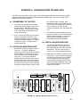
The DSP4 has 5 sockets for memory chips. Two sockets hold 8 K Random Access Memory (RAM)
chips and two hold Programmable Read Only Memory (PROM) chips. There is one empty socket
between the two types of memory.
A.1 DISASSEMBLY OF THE DSP4
1. Turn power off, remove the four Phillips
head screws located near the edge of the
top and bottom of the DSP4. Place the
DSP4 face down. Carefully lift the outside
cover of the DSP4 up and away form the
inside circuit boards.
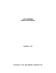
2. Figure 1 shows the CPU card; the memory
chips are opposite the connector. The
locations numbered 1 and 2 hold PROM
chips (with Campbell Scientific, Inc. labels).
Location 3 is empty. Locations 4 and 5
contain RAM chips.
A.2 INSTALLING NEW PROM CHIPS
1. PROMS are located at locations 1 and 2 in
Figure A-1. To replace a RAM chip,
carefully pry the old chip up with a small flat
blade screwdriver. Start at one end and
then loosen the other, alternating until the
chip is free. The new chip should be
installed with the notched end in the same
direction as the other chips, to the edge of
the card (see Figure A-1). Before pushing
the chips into the socket, make certain that
all pins are correctly seated. Start one side
first, then the other, if needed. After
installing the chip, check for pins that may
be bent or not firmly seated in the socket. If
there is a bent pin, remove the chip,
carefully straighten the pin, and reinstall the
chip.
2. The PROM chip with the lowest number is
inserted in socket 1, and the PROM with the
highest number in socket 2. In the event
you have special PROMS, check the
documentation that came with them.
A.3 INSTALLING NEW RAM CHIPS
1. The standard DSP4 has the maximum
memory allowable. In the unlikely event
that a RAM chip fails, the DSP4 can detect
the bad chip. The error code is given in
section 2.3.1, as to the problem detected.
2. RAM chips are installed in locations 4 and 5
in Figure A-1. The procedure for changing
an RMA chip is the same as for a PROM
chip - carefully pry out the old chip and
insert the new one, being certain that the
notch on the chip is toward the close edge
of the card and that all pins are correctly
seated in the sockets.
FIGURE A-1. Memory Sockets on the CPU Card
A-1