1
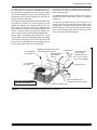
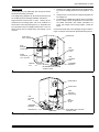
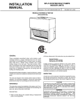
INSTALLATION
INSTRUCTION
OUTDOOR SPLIT-SYSTEM
AIR CONDITIONER
MODELS: 10, 12, 13 AND 14 SEER
1 PHASE - 1.5 TO 5 TONS
TABLE OF CONTENTS
GENERAL INFORMATION . . . . . . . . . . . . . . . . . . . . 2
INSPECTION . . . . . . . . . . . . . . . . . . . . . . . . . . . . . . 2
REFERENCE . . . . . . . . . . . . . . . . . . . . . . . . . . . . . . 2
LIMITATIONS . . . . . . . . . . . . . . . . . . . . . . . . . . . . . . 2
CHECK ELECTRICAL POWER SUPPLY . . . . . . . . . 2
SELECTING EQUIPMENT LOCATION . . . . . . . . . . 2
INSTALLATION . . . . . . . . . . . . . . . . . . . . . . . . . . 4
OUTDOOR UNIT . . . . . . . . . . . . . . . . . . . . . . . . . . . . 4
INDOOR UNITS . . . . . . . . . . . . . . . . . . . . . . . . . . . . 4
REFRIGERANT LINE (SWEAT FIT) . . . . . . . . . . . . . 4
INSULATION OF VAPOR LINE . . . . . . . . . . . . . . . . 4
RE-ASSEMBLING, BRAZING AND CLEANING OF
JOINT CONNECTIONS . . . . . . . . . . . . . . . . . . . . . . 5
REFRIGERANT LINE SUPPORT . . . . . . . . . . . . . . . 5
CHARGING AND LEAK TESTING . . . . . . . . . . . . . . 5
TOTAL LINE LENGTH . . . . . . . . . . . . . . . . . . . . . . . 5
ORIFICE SELECTION (ON SWEAT FIT COILS) . . . 5
REFRIGERANT VALVE OPERATION . . . . . . . . . . . 6
OIL TRAPPING . . . . . . . . . . . . . . . . . . . . . . . . . . . . . 6
SYSTEM CHARGE . . . . . . . . . . . . . . . . . . . . . . . 8
MEASUREMENT METHOD . . . . . . . . . . . . . . . . . . . 8
SUPERHEAT CHARGING METHOD . . . . . . . . . . . . 8
CHECKOUT PROCEDURE . . . . . . . . . . . . . . . . . . 10
SYSTEM OPERATION CHECKOUT . . . . . . . . . . . 10
CAUTION:READ ALL SAFETY GUIDES BEFORE
YOU START TO INSTALL YOUR UNIT.
SAVE THIS MANUAL
035-13606-003 Rev. A (202)
035-13606-003 Rev. A (202)
GENERAL INFORMATION
These outdoor units are designed to be connected to a
matching UPG indoor coil with sweat connection lines. These
units are factory charged with refrigerant for a matching
indoor coil plus 15 feet of field supplied line. The outside unit
is designed to be placed alongside or at the back of the
home, remote from the indoor coil. The outdoor unit has been
factory run-tested and all components of the system are
ready for easy, immediate installation.
The manufacturer is not responsible for the performance of a mismatched system. The outdoor
unit must be installed with a compatible indoor
unit as designated in the specification data or in
the Directory of Certified Unitary Heat Pumps
published by the Air Conditioning and Refrigeration Institute. Using unmatched components may
not only affect the performance of the system, but
may also void the warranty of the equipment.
Do not install any coil in a furnace which is to be
operated during the heating season without
attaching the refrigerant lines to the coil. Allowing
the coil charge to enter the refrigerant lines prevents excessive refrigerant pressure build-up and
possible coil damage.
INSPECTION
Check the unit thoroughly for shipping damage, Unusually
rough handling during shipment may loosen fan motors, compressors, or other components. Be sure that the unit is ready
to operate before installing it. If there is damage, file a claim
with the shipper. See Form 50.15-NM for more information.
REFERENCE
Use this instruction in conjunction with the instructions for the
appropriate indoor unit, air moving system and accessories.
Table 1: APPLICATION LIMITATIONS
Installer should pay particular attention to the words NOTE,
CAUTION and WARNING.
Ambient Air Temperature
on Outdoor Coil
NOTES are intended to clarify or make the installation easier.
CAUTIONS identify procedures which, if not followed carefully, could result in personal injury, property damage or
equipment damage.
WARNINGS are given to alert the installer that severe personal injury, death or equipment damage may result if installation procedures are not followed properly.
LIMITATIONS
The unit should be installed in accordance with all national
and local codes and regulations which govern the installation
of this type of equipment. In lieu of local codes, the equipment should be installed in accordance with National Electric
Code, and in accordance with the recommendations made by
the National Board of Fire Underwriters.
Limitations for the indoor unit, coil and appropriate accessories must also be observed.
The outdoor unit must not be installed with any duct work in
the air stream. The outdoor fan is the propeller type and is not
designed to operate against any additional external static
pressure.
The maximum and minimum conditions for operation must be
observed to assure a system that will give maximum performance with minimum service.
2
Air Temperature on
Indoor Coil
Min. °DB
Max. °DB
Min.
Max.
50
120
57
72
CHECK ELECTRICAL POWER SUPPLY
The electrical power should be checked to determine if adequate power is available, and near constant voltage can be
maintained. If there is any question concerning the power
supply, contact the local power company for corrections; otherwise, unsatisfactory performance may result.
SELECTING EQUIPMENT LOCATION
Several important factors must be considered before selecting the site for the outdoor unit:
•
•
•
•
•
•
•
•
•
•
•
Distance to indoor coil
Proximity to the structure
Proximity to vents and exhaust systems
Ability to service
Sound transmission
Air circulation
Wind direction
Relationship between structure, sun, and unit
Distance from power source
Water drainage
Local codes
Locate the outdoor unit near enough to the indoor coil vicinity
to eliminate lengthy refrigerant line runs. Do not locate the
outdoor unit so it discharges air under eaves or gutters. Rain
or snow melt-off should not be able to run off a roof and down
upon the unit. Be sure vents are not located upwind from the
outdoor unit.
Unitary Products Group
035-13606-003 Rev. A (202)
A minimum clearance of 18 inches is required for service at
the control panel and compressor compartments access. A
10 inch clearance is required for the air inlet to the outdoor
coil around the perimeter of the unit. The air discharge of the
unit requires a 60 inch clearance between the top of the unit
and any obstruction. See Figure 1.
Provide ample clearance from shrubs to allow adequate air to
pass across the outdoor coil without leaves or branches
being pulled into the coil.
The length of the refrigerant tubing, between the outdoor unit
and indoor coil, should be as short as possible to avoid
capacity and efficiency loss. Excessive spacing of the outdoor unit from the home can lead to the refrigerant lines
being restricted by trampling or by being punctured by lawn
mowers. Locate the outdoor unit away from bedroom windows or other rooms where sound might be objectionable.
The unit must be located outdoors and must not be connected to duct work. It is recommended the outdoor unit be
mounted upon a solid base that will not shift or settle. Top of
base should be two inches above grade. Thought should be
given to water drainage away from the outdoor unit. Drain
holes in the base pan must be kept clear.
Consideration should be given to the distance and routing of
electrical service that would have to be run to connect the
outdoor unit.
Adverse effects of prevailing winds, blowing snow or sleet
onto the outdoor coil can be eliminated by placing the outdoor
unit where the wind does not blow across the unit. Trees,
shrubs, corners of buildings and fences standing off from the
coil can reduce capacity loss due to wind chill effect.
60” OVERHEAD
CLEARANCE
MINIMUM 24” SERVICE ACCESS
THERMOSTAT TO FURNACE OR
CLEARANCE ON ONE SIDE
AIR HANDLER
WEATHERPROOF
TERMINAL BLOCK
DISCONNECT
NEC
CLASS 1 WIRING
SWITCH
NEC CLASS 2 WIRING
10” CLEARANCE
COIL AREA
NOTE: ALL OUTDOOR WIRING
MUST BE WEATHERPROOF.
TO INDOOR COIL
SEAL OPENING(S) WITH
PERMAGUM OR EQUIVALENT
CONTROL ACCESS PANEL
FIGURE 1 : TYPICAL RESIDENTIAL OUTDOOR UNIT LOCATION
Unitary Products Group
3
035-13606-003 Rev. A (202)
INSTALLATION
Use only ACR grade copper tubing and keep ends sealed
until joints are made.
OUTDOOR UNIT
After the site has been selected, a solid base pad that will not
shift or settle should be provided. The base pad should not
come in contact with the foundation or side of the structure
because sound may be transmitted to the residence. The pad
should be located far enough away from the structure so the
outdoor unit is not closer than its minimum distances. See
Figure 1. Set the outdoor unit upon the pad with care to avoid
damage..
The correct diameters of the refrigerant lines are listed in the
Tabular Data Sheet.
For best performance, select routing of refrigerant lines for
minimum distance and fewest number of bends.
Determine the path that the refrigerant lines will follow.
Starting at either the indoor coil or the outdoor unit refrigerant
line connections, carefully measure, cut, de-burr and fit copper refrigerant lines along the path previously determined.
NOTE: If it is necessary for bends to be formed in the vapor
line, the radius should not be less than 12 inches.
Do not remove the protective caps or plugs from
the unit refrigerant connections until the refrigerant lines are run and ready for final connection. If
this procedure is not observed, dirt and other particles will get into the system and plug various orifices and small tubes.
INDOOR UNITS
Cut ends of the copper tubing square.
Remove all burrs from tubing with a reamer, file or de-burring
tool.
When the indoor coil is above the outdoor unit, the vapor line
should be sloped toward the outdoor unit with a fall of at least
1/4 inch per 5 feet.
Install the indoor coil in the furnace or air handler according to
the installation instructions packed with each component.
When the outdoor unit is above the indoor coil the horizontal
runs should be sloped toward the outdoor unit as described
above.
REFRIGERANT LINE (SWEAT FIT)
INSULATION OF VAPOR LINE
The following steps are very important when setting up a
refrigeration system and need to be followed completely to
insure that a strong, flexible and leak tight system is obtained.
Insulate vapor line with 3/8" (or that required by local code)
closed cell insulation.
The installation of the copper refrigerant tubing must be done
with care to obtain reliable, trouble-free operation.
1.
Selection of proper refrigerant tubing grade and size.
2.
Refrigerant line routing, cutting and fitting.
3.
Insulating the vapor line.
4.
Connecting the refrigerant lines to the indoor coil and
outdoor unit.
5.
Proper preparation of joint connections.
6.
Reassembling, cleaning and brazing the joint connections.
7.
Pressure leak test all joints.
8.
Evacuate refrigerant lines and indoor coil.
9.
Charging refrigeration system (If the line length is other
than 15 feet). See Table 2.
Slide tubing insulation onto the vapor line so that it is covered
completely from the indoor coil to the outdoor unit. Be sure
that the tubing is capped before sliding on insulation.
It is not necessary to insulate the liquid line, unless it is subject to excess heat in an uninsulated area.
NOTE: In areas of extreme temperatures and humidity,
additional insulation may be required to prevent excessive
condensation and loss of capacity.
Do not insulate liquid line and vapor line together. Liquid line
should not be in contact with the vapor line. See Figure 2.
Tape
Liquid
Line
Incorrect
Table 2: REFRIGERANT LINE CHARGE
4
LIQUID OD
VAPOR OD
R-22 CHARGE, OZ/FT
3/8"
5/8"
0.66
3/8"
3/4"
0.68
3/8"
7/8"
0.70
3/8"
1-1/8"
0.76
Correct
Sheet Metal Hanger
Insulated Vapor Line
FIGURE 2 : INSULATION OF VAPOR LINE
Unitary Products Group
035-13606-003 Rev. A (202)
RE-ASSEMBLING, BRAZING AND CLEANING OF
JOINT CONNECTIONS
When using hard solder, an inert gas such as dry
nitrogen must be introduced and permitted to
flow through tubing during brazing to displace air
and prevent oxidation.
Remove the Schrader Valve cores from the service valves.
Remove the plugs from the service valve field tubing connections. Clean the joints to be brazed.
NOTE: Do not overheat the connection to be brazed as this
can cause improper flow of solder, resulting in a weak and
leaking joint. Never apply heat directly to face of fitting. Do
not heat solder by direct contact with flame of the torch.
When brazing copper tubing it is very important to preheat
the entire joint before applying the solder. This is done by
sweeping the flame steadily and evenly around the fitting, to
bring both fitting and tubing up to equal temperature before
applying the solder.
Reassemble groups of tubing and fittings, brazing several
joints instead of one joint at a time. This reduces the chance
for error in the alignment of the assembly. Replace Schrader
Valve cores. DO NOT OPEN SERVICE VALVES AT THIS
TIME.
Clean joint connection immediately after brazing with wet rag.
When recovering refrigerant from a system, with a burnout,
follow a safe procedure due to possible contamination.
Avoid getting the refrigerant in the eyes or on the
skin.
Contaminated refrigerant must be recovered and returned to
the local refrigeration supply house for proper disposition.
TOTAL LINE LENGTH
Units should be installed only with approved system combination (indoor/outdoor) as specified in the Technical Guide.
For systems with total line length exceeding 50 feet, see
APPLICATION DATA and work sheet "General Piping Recommendations and Refrigerant Line Length" for vapor and
liquid line sizing, calibration of liquid line pressure loss or
gain, determination of vapor line velocity, elevation limitations, orifice connections, system charging, traps, etc.
Systems with liquid line pressure loss or gain greater than 11
psi must be provided with corrected orifice size as noted in
.APPLICATION DATA.
ORIFICE SELECTION (ON SWEAT FIT COILS)
NOTE: The proper orifice must be installed in the indoor coil
liquid line connection prior to the connection of the refrigerant
lines.
REFRIGERANT LINE SUPPORT
Refrigerant lines should be supported in a way that no dips or
sags occur. We recommend four feet between supports. If
refrigerant lines are to be attached to the home structure,
care should be taken to eliminate the transmission of vibrations. Attach the refrigerant lines to the indoor coil first.
Remove plugs from the indoor coil, then clean joints to be
brazed. Braze refrigerant lines to the indoor coil. Attach refrigerant lines to the outdoor unit.
CHARGING AND LEAK TESTING
On systems with or without service valves the refrigerant
should be recovered or recycled in accordance with EPA regulations. In some cases this may require putting piercing
valves on both the high and low sides of the system.
DO NOT vent refrigerant to the outdoors.
Unitary Products Group
Coil is under 30 to 35 psig (inert gas) pressure.
Each coil has an orifice installed in the fitting
between the liquid line connection and distributor.
The orifice is identified on a label next to the liquid line connection.
The orifice shipped with the outdoor unit is based on the
“most sold” combination, but it may be changed, depending
on the capacity and efficiency of the outdoor unit, elevation
differences, and/or long total line lengths. An additional orifice(s) is shipped with most outdoor units for the most commonly required replacement combinations. Other sizes must
be ordered from Source 1 Parts if required.
See the appropriate Tabular Data Sheet for the correct orifice
size and charge adder. If the orifice size matches, nothing further is required and the refrigerant lines may be connected
per the outdoor unit instruction. However, if another orifice
should be used, see the coil instruction for details to change
the orifice in the coil.
5
035-13606-003 Rev. A (202)
REFRIGERANT VALVE OPERATION
All outdoor units are shipped with the service
valves in the closed position. After installation of
the refrigerant and proper evacuation, make sure
that all valves are in the open position and that
the caps are securely tightened before turning
ON the electrical power to the outdoor unit.
All models in this series have brass service valves. These
valves are not back seating. Opening or closing valve does
not close service port. Service ports have Schrader valves for
gauge connections. Use back-up wrench on valve body when
removing cap to open or close the valve. To open, insert hex
wrench into stem and back out counter clockwise until stem
ELECTRICAL WIRING
To prevent electrical shock, open remote disconnect so electrical supply to outdoor unit is shut
off. Contactor does not open both sides of the
208/230 volt electrical circuit.
POWER SUPPLY
All wiring must comply with N.E.C. and local codes. See rating plate and product data sheet for volts, frequency, phase,
maximum fuse size and minimum branch circuit ampacity.
Refer to the wiring diagram inside the unit control box cover
before connecting to power supply.
1.
The 208/230 volt single phase line voltage service wiring
for the outdoor unit must include a disconnect switch
located within sight of the outdoor unit.
2.
Use the correct size fuse or circuit breaker as listed on
the unit rating plate and data sheet. If using nonmetallicsheathed cable (NM or NM-B) ampacities shall be that of
60° C conductors per N.E.C 336-26.
3.
Wiring connections. - Two are provided in the control
box:
just touches retaining ring.
If the valve stem is backed out beyond the retaining ring, system pressure could force the stem
out of the valve body and possibly cause personal injury. In the event that the retaining ring is
missing do not attempt to open the valve.
Some units may have factory installed 1-1/8" ball valves. To
open the valve, remove the brass valve stem cap, located on
the side of the valve, with an adjustable wrench. Next, turn
the valve stem 1/4 turn CCW (away from unit).
All caps must be replaced to prevent leaks.
Replace valve cap finger tight, then tighten an additional 1/6
of a turn with a wrench, using a back-up wrench on the valve
body.
OIL TRAPPING
When the outdoor unit is above the indoor coil oil trapping is
necessary. Please refer to APPLICATION DATA, 690.01AD1V (1296) and worksheet 690.01-AD1.1V (791) “General
Piping Recommendations and Refrigerant Line length".
Check the system for correct charge after all components of
the system have been installed, connected and wired correctly.
Connect service gauges to low pressure port and discharge
service ports.
Allow unit to operate until system pressures and temperatures have stabilized, making sure that the pressure and temperature align with unit service data. If not, check system
charge and adjust if necessary.
6
a.
One for low voltage wiring.
b.
One entrance for high voltage L1 and L2.
The adjustable High Voltage Conduit Plate is factory installed
for 1/2" conduit connections. For 3/4" conduit, remove the
screw holding the plate in place and adjust the location of the
holes. For 1" conduit, remove the conduit plate and discard.
Re-install screw to maintain the integrity of the unit structure,
regardless of the conduit being used. See Figures 9, 10 & 11.
4.
Power connection to the unit is facilitated by screw terminals, L1 and L2 on the outdoor unit contactor. See Figures 9, 10 & 11.
5.
Ground the outdoor unit using the ground lug provided.
Unless the outdoor unit is grounded through proper wiring to the service entrance ground, a suitable separate
ground should be provided at the outdoor unit.
6.
Use copper conductors only.
Casing or cabinet must be permanently grounded
in accordance with National Electric Code or
other applicable local codes.
Unitary Products Group
035-13606-003 Rev. A (202)
LOW VOLTAGE
Control wiring may vary depending upon the type of thermostat and furnace being connected.
Low voltage wiring diagrams can be found with the furnace or
air conditioning blower package installation instructions.
Pig-tail connector wires (2 blue or 1 blue, 1 brown) are provided from the low voltage pull-in coil on the contactor to a
section of the control box (See Figure 12). A “Fingered” bushing is provided in the low voltage knockout hole. If 1/2" conduit is used for the low voltage wiring, the bushing is to be
removed.
1.
Route the low voltage cable through the fingered bushing in the low voltage junction box. See Figures 9, 10 &
11.
2.
Using wire nuts, connect the low voltage wiring within the
low voltage box.
3.
A minimum of 19 AWG wire must be used in connecting
the low voltage control wiring between the outdoor unit,
air handler thermostat, and outdoor thermostat. For
longer low voltage control wiring lengths, consult the
N.E.C.
Connect thermostat and control package wiring as shown in
Figure 12 and per the instructions packed with those pieces.
CONTACTOR
START RELAY
(Not on all Models)
DUAL
RUN/FAN
CAPACITOR
FAN
MOTOR
PLUG
START
CAPACITOR
LOW
VOLTAGE
BOX
(Not on all Models)
“FINGERED”
BUSHING
GROUND
LUG
REVERSIBLE HIGH VOLTAGE
CONDUIT PLATE
FIGURE 3 : Typical Condensing Unit Control Box (Start Components Shown)
START RELAY
CONTACTOR
DUAL
RUN/FAN
CAPACITOR
LOW
VOLTAGE
BOX
FAN
MOTOR
PLUG
“FINGERED”
BUSHING
GROUND LUG
ADJUSTABLE HIGH VOLTAGE
CONDUIT PLATE
FIGURE 4 : Typical Condensing Unit Control Box (Start Components Shown)
Unitary Products Group
7
035-13606-003 Rev. A (202)
E
ALL FIELD WIRING TO BE IN ACCORDANCE WITH ELECTRIC CODE (NEC) AND/OR LOCAL CODES
POWER WIRING
POWER WIRING
208/230-1-60
CONTROL WIRING
230 - 1 - 50
24 VOLT CONTROL WIRING
FACTORY WIRING
MINIMUM 18 GA. WIRE
(NEC CLASS 2)
FURNACE OR AIR HANDLER TERMINAL BLOCK
C
Y
R
G
W
* TERMINAL W IS ONLY
REQUIRED ON SYSTEMS
WITH HEAT.
CONTACTOR
TERMINALS
GND.
LUG
COIL
Y
R
G
W
*
ROOM THERMOSTAT
CONDENSING UNIT
ALL OUTDOOR WIRING MUST BE WEATHERPROOF. USE COPPER CONDUCTORS ONLY.
FIGURE 5 : TYPICAL FIELD WIRING
SYSTEM CHARGE
The factory charge in the outdoor unit includes enough
charge for the unit and a most sold matched evaporator.
Some indoor coil matches may require some additional
charge. See Tabular Data sheet provided in unit literature
packet.
Sweat connect units also include sufficient charge for 15 feet
of lines. Pre-charged line lengths are factory charged with the
correct amount of refrigerant required. Table 2 lists the refrigerant line charges.
Refrigerant charging should only be carried out
by a qualified air conditioning contractor.
MEASUREMENT METHOD
If a calibrated charging cylinder or accurate weighing device
is available, add refrigerant accordingly.
The “TOTAL SYSTEM CHARGE” must be permanently
stamped on the unit data plate.
Compressor damage will occur if system is
improperly charged. On new system installations
charge system per R-22 charge information label
and follow guidelines in this instruction.
Check flare caps on service ports to be sure they
are leak tight. DO NOT OVER TIGHTEN
(between 40 and 60 inch - lbs. maximum).
Total system charge is determined as follows:
1.
Determine outdoor unit charge from tabular data sheet.
2.
Determine indoor coil adjustment from tabular data
sheet.
3.
Calculate the line charge using Table 2 factors. Calculate
over 15 feet of sweat lines for sweat connect units.
NOTE: For sweat connect lines, the line charge over 15 feet
should be included on the data plate and must be added to
the system.
4.
Total system charge = item 1 + item 2 + item 3.
5.
Permanently stamp the unit data plate with the total
amount of refrigerant in the system.
Use one of the following charging methods whenever additional refrigerant is required for the system charge.
8
SUPERHEAT CHARGING METHOD
NOTE: Use this method only during system maintenace
and repair.
1.
Operate system until temperatures and pressures stabilize (minimum of 10 minutes).
2.
Measure and record indoor wet bulb (WB) temperature
using a sling psychrometer and the outdoor dry bulb
(DB) temperature using a thermometer.
Unitary Products Group
035-13606-003 Rev. A (202)
Table 3: SUPERHEAT VALUE
OUTDOOR DB°F
INDOOR WB
°F1
55
60
65
70
75
80
85
90
95
100
105
110
115
50
9
7
52
12
10
6
54
14
12
10
7
56
17
15
14
10
58
20
18
16
13
9
5
60
23
21
19
16
12
8
6
62
26
24
22
19
16
12
8
5
64
29
27
24
21
18
15
11
9
66
32
31
30
24
23
18
15
11
9
6
68
35
33
30
27
24
21
19
16
14
12
9
6
35
33
30
28
25
22
20
18
15
13
11
8
35
33
30
28
26
24
20
20
17
15
14
34
31
30
27
25
23
22
20
18
35
33
31
29
27
26
25
23
70
72
74
6
76
1.
6
Evaporator Entering Air °F
Table 4: TEMPERATURE AND PRESSURE
SUCTION
PRESSURE
PSIG
(Service Port)
1.
SUCTION SERVICE VALVE SUPERHEAT
01
2
4
6
8
10
12
14
16
18
20
22
24
26
28
30
32
34
61.5
35
37
39
41
43
45
47
49
51
53
55
57
59
61
63
65
67
69
64.2
37
39
41
43
45
47
49
51
53
55
57
59
61
63
65
67
69
71
67.1
39
41
43
45
47
49
51
53
55
57
59
61
63
65
67
69
71
73
70.0
41
43
45
47
49
51
53
55
57
59
61
63
65
67
69
71
73
75
73.0
43
45
47
49
51
53
55
57
59
61
63
63
67
69
71
73
75
77
76.0
45
47
49
51
53
55
57
59
61
63
65
67
69
71
73
75
77
79
79.2
47
49
51
53
55
57
59
61
63
65
67
69
71
73
75
77
79
81
82.4
49
51
53
55
57
59
61
63
65
67
69
71
73
75
77
79
81
83
Saturation Temperature
Table 5: R-22 SATURATION PROPERTIES
TEMP.
°F
PRESSURE
PSIG
TEMP.
°F
PRESSURE
PSIG
TEMP.
°F
PRESSURE
PSIG
TEMP.
°F
PRESSURE
PSIG
TEMP.
°F
PRESSURE
PSIG
45
76.02
60
101.62
75
132.22
90
168.40
105
210.75
46
77.58
61
103.49
76
134.45
91
171.02
106
213.81
47
79.17
62
105.39
77
136.71
92
173.67
107
216.90
48
80.77
63
107.32
78
138.99
93
176.35
108
220.02
49
82.39
64
109.26
79
141.30
94
179.06
109
223.17
50
84.03
65
111.23
80
143.63
95
181.80
110
226.35
51
85.69
66
113.22
81
145.99
96
184,56
111
229.56
52
87.38
67
115.24
82
148.37
97
187.36
112
232.80
53
89.08
68
117.28
83
150.78
98
190.18
113
236.08
54
90.81
69
119.34
84
153.22
99
193.03
114
239.38
55
92.56
70
121.43
85
155.68
100
195.91
115
242.72
56
94.32
71
123.54
86
158.17
101
198.82
116
246.10
57
96.11
72
125.67
87
160.69
102
201.76
117
249.50
58
97.93
73
127.83
88
163.23
103
204.72
118
252.94
59
99.76
74
130.01
89
165.80
104
207.72
119
256.41
Unitary Products Group
9
035-13606-003 Rev. A (202)
3.
Measure and record the suction pressure at the suction
service valve port.
6.
Is air filter installed and clean?
7.
Is the blower motor speed set correctly?
4.
Using Table 4, note the superheat value corresponding
to the intersection of the indoor wet bulb and the outdoor
dry bulb.
5.
With the superheat value obtained in step 4 and the suction pressure value from step 3, find the intersection of
the values in Table 5. This is the required suction tube
temperature at the suction service valve.
IMPORTANT - Installer should place unit data sheet and
installation instructions in customer packet and give to home
owner after installation is complete.
6.
To bring the tube temperature in line with the required
value from Table 5, add refrigerant to the service port to
cause the tube temperature to fall and reclaim refrigerant
to cause the temperature to rise.
SYSTEM OPERATION CHECKOUT
1.
With thermostat set to the OFF position, close disconnect switch or switches to complete circuits to condensing unit and furnace. Set thermostat to call for cooling.
2.
After the system starts, check the voltage and amperage
at the condensing unit contactor.
3.
If voltage is not within 10% of rated voltage, or amperage
greatly exceeds nameplate amperage, shut down the
system and contact the local power company for corrections; otherwise unsatisfactory performance may result.
CHECKOUT PROCEDURE
Use the following list to see that nothing was over looked:
1.
Have all braze joints on refrigerant lines been leak
checked? (Sweat Fit Units)
4.
With the system in operation, check the condensing unit
for unusual noise and undue vibration.
2.
Line set fittings leak checked? (Quick Connect Units)
5.
3.
Have base valves been opened? (Sweat Fit Units only)
4.
Have all refrigerant lines been secured and isolated
properly?
Allow the system to operate until it is balanced or stabilized (approximately 30 minutes), before making further
checks.
6.
5.
Is the indoor coil drain hooked up and draining freely?
Pour water in drain pan.
Remove manifold gages hoses, and install cap on
Schrader valves.
10
Unitary Products Group
035-13606-003 Rev. A (202)
SERVICE RECORDS
Unitary Products Group
11
Subject to change without notice. Printed in U.S.A.
Copyright © by York International Corp. 2002. All rights reserved.
Unitary
Products
Group
035-13606-003 Rev. A (202)
Supersedes: 035-13606-002, 550.46-N1Y (199)
5005
York
Drive
Norman
OK
73069