1
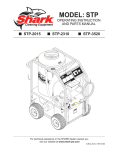
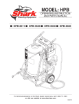
MODEL: STP
OPERATING INSTRUCTION
AND PARTS MANUAL
■ STP-2015
■ STP-2310
■ STP-3520
For technical assistance or the SHARK dealer nearest you, call 1-479-750-4475,
1-800-771-1881 or visit our website at www.shark-pw.com
2
CONTENTS
●
Pump Volume At Pump Head:
STP-2015 1.9 GPM
STP-2310 2.1 GPM
STP-3520 3.5 GPM
●
Total Machine Amperage:
STP-2015 20 Amps
STP-2310 15 Amps
STP-3520 22 Amps
●
Pump Pressure At Pump Head:
STP-2015 1500 PSI
STP-2310 1000 PSI
STP-3520 2000 PSI
●
Shipping Weight:
STP-2015 330 Lbs.
STP-2310 330 Lbs.
STP-3520 340 Lbs.
●
Machine Voltage:
STP-2015 120V/1PH
STP-2310 120V/1Ph
STP-3520 230V/1Ph
●
Machine Dimensions:
STP-2015
STP-2310
STP-3520
Length = 39"
Length = 39"
Length = 39"
Width = 27"
Width = 27"
Width = 27"
SERIAL NUMBER:
DATE PURCHASED:
FOR SALES AND SERVICE, PLEASE CONTACT:
Shark STP Manual • Form 97-6153 • Revised 3/04
Height = 44"
Height = 44"
Height = 44"
3
MACHINE SPECIFICATIONS
Introduction ............................................................ 4
STP Exploded View Parts List ....................... 14-15
Important Safety Information ............................. 4-5
Control Panel Exploded View and Parts List ...... 16
Installation ......................................................... 5, 7
Hose & Spray Gun Assembly and Parts List ..... 17
Component Identification ...................................... 6
Downstream Injector Assembly and Parts List .. 18
Starting and Operating Instructions ..................... 7
Troubleshooting .............................................. 19-21
How To Use The Detergent Injector ...................... 8
Maintenance Schedule ........................................ 22
Preventative Maintenance ..................................... 9
Oil Change Record .............................................. 22
Maintenance and Service ................................ 9-11
Warranty
STP Exploded View ........................................ 12-13
Shark STP Manual • Form 97-6153 • Revised 3/04
4
STP SERIES PRESSURE WASHER
INTRODUCTION
WARNING
Thank you for purchasing a STP.
This manual covers the operation and maintenance
of the STP Series pressure washers. All information in
this manual is based on the latest product information
available at the time of printing.
We reserve the right to make changes at any time without incurring any obligation.
Owner/User Responsibility:
The owner and/or user must have an understanding of
the manufacturer’s operating instructions and warnings
before using this pressure washer. Warning information
should be emphasized and understood. If the operator
is not fluent in English, the manufacturer’s instructions
and warnings shall be read to and discussed with the
operator in the operator’s native language by the purchaser/owner, making sure that the operator comprehends its contents.
Owner and/or user must study and maintain for future
reference the manufacturers’ instructions.
This manual should be considered a permanent
part of the machine and should remain with it
if machine is resold.
When ordering parts, please specify model and
serial number.
IMPORTANT SAFETY
INFORMATION
CAUTION: To reduce the risk of
injury, read operating instructions carefully before using.
1. Read the owner's manual thoroughly. Failure to follow instructions could cause malfunction
of the machine and result in
READ OPERATOR’S
MANUAL THOROUGHLY
death, serious bodily injury and/
PRIOR TO USE.
or property damage.
2. All installations must comply with local codes. Contact your electrician, plumber, utility company or the
selling distributor for specific details.
To comply with National Electrical Code (NGPA 70)
and provide additional protection from risk of electric shock, this hot water converter is equipped with
a UL approved ground fault circuit interrupter (GFCI)
power cord.
CAUTION
Shark STP • 97-6153 • Rev. 3/04
OPERATOR’S MANUAL
RISK OF FIRE.
DO NOT USE WITH
FLAMMABLE
LIQUIDS.
WARNING: Flammable liquids
can create fumes which can ignite
causing property damage or severe injury.
WARNING: Do not use gasoline,
crankcase drainings or oil containing gasoline, solvents or alcohol. Doing so will result in fire
and/or explosion.
WARNING: Do not spray flammable liquids. Operate
only where an open torch is permitted.
3. This fuel burning machine shall be installed only in
locations where combustible dusts and flammable
gases or vapors are not present.
4. In these oil burning models, use only kerosene, No.1
home heating fuel, or diesel fuel.
WARNING: Keep water spray,
WARNING wand and high pressure hose
away from electrical wiring or fatal electric shock may result. Read
warning tag on electrical cord.
5. To protect the operator from
electrical shock, the machine
KEEP WATER SPRAY
AWAY FROM
must be electrically grounded.
ELECTRICAL
It is the responsibility of the
WIRING.
owner to connect this machine
to a UL grounded receptacle of proper voltage and
amperage ratings. Do not spray water on or near
electrical components. Do not touch machine with
wet hands or while standing in water. Always disconnect power before servicing.
CAUTION: Spray gun kicks back — hold with both
hands.
6. Grip cleaning wand of attached pressure washer securely with both hands before starting cleaner. Failure to do this could result in injury from a whipping
wand.
WARNING: High pressure stream
WARNING of fluid that this equipment can
produce can pierce the skin and
its underlying tissues, leading to
serious injury and possible amputation.
HIGH PRESSURE
7. High pressure developed by the
SPRAY CAN PIERCE
attached pressure washer can
SKIN AND TISSUES.
cause bodily injury or damage.
Use caution when operating. Do not point the spray
gun at anyone or at any part of the body. This machine is to be used only by qualified operators.
8. Never make adjustments on machine while it is in
operation.
STP SERIES PRESSURE WASHER
WARNING
PROTECTIVE
EYEWEAR AND
CLOTHING MUST
BE WORN.
WARNING
RISK OF
ASPHYXIATION.
USE ONLY IN A WELL
VENTILATED AREA.
WARNING: High pressure spray
can cause paint chips or other
particles to become airborne and
fly at high speeds.
9. Eye safety devices must be
worn when using this equipment.
WARNING: Risk of asphyxiation
— Use this product only in a well
ventilated area.
10. When the machine is working,
do not cover or place in a closed
space where ventilation is insufficient.
WARNING: Risk of fire. Do not add
fuel when the machine is operating or still hot.
11. Machines with a spray gun
should not be operated with
the spray gun in the off position
RISK OF FIRE.
for extended periods of time as
DO NOT ADD FUEL
WHEN OPERATING
this may cause damage to the
MACHINE.
pump. Check to make sure
burner shuts off when spray gun trigger is closed.
12. Protect from freezing.
13. To prevent a serious injury, make certain quick coupler on discharge hose has locked before using pressure washer.
14. Do not allow acids, caustic or abrasive fluids to pass
through the pump.
15. Inlet water must be cold and clean fresh water.
16. Do not allow CHILDREN to operate the pressure
washer at any time. THIS MACHINE MUST BE
ATTENDED DURING OPERATION.
17. The best insurance against an accident is precaution, and knowledge of the machine.
18. Do not operate this product when fatigued or under
the influence of alcohol or drugs. Keep operating area
clear of all persons.
19. We will not be liable for any changes made to our
standard machines, or any components not purchased from us.
20. Do not overreach or stand on unstable support. Keep
good footing and balance at all times.
21. Follow the maintenance instructions specified in the
manual.
WARNING
Shark STP • 97-6153 • Rev. 3/04
OPERATOR’S MANUAL
5
22. When making repairs disconnect from electrical
source.
23. Turn burner off and open spray gun to allow water to
flow and cool coil to 100°F before turning machine
off.
24. Before disconnecting high pressure hose from
hot water outlet, turn off burner to allow water to cool
to 100°F, then turn off pump motor and water supply
and operate spray gun to relieve back pressure in
hose. This will prevent coil damage from thermal expansion.
CAUTION: This machine produces hot water and
must have insulated components attached to protect the operator.
INSTALLATION
Place machine in a convenient location providing ample
support, draining and room for maintenance.
This machine is intended for indoor use. Machine
must be stored indoors when not in use.
Location:
The location should protect the machine from damaging environmental conditions, such as wind, rain, and
freezing.
1. This machine should be run on a level surface where
it is not readily influenced by outside sources such
as strong winds, freezing temperatures, rain, etc.
It should be located to allow accessibility for refilling
of fuel, adjustments and maintenance. Normal
precautions should be taken by the operator of the
machine to prevent moisture from reaching the
electrical controls.
2. It is recommended that a partition be made between
the wash area and the machine to prevent water
spray from coming in contact with the machine. Excess moisture reaching any electric components or
electrical controls will reduce machine life and may
cause electrical shorts.
3. During installation of the machine, beware of poorly
ventilated locations or areas where exhaust fans may
cause an insufficient supply of oxygen. Sufficient
combustion can only be obtained when there is a
sufficient supply of oxygen available for the amount
of fuel being burned. If it is necessary to install a
machine in a poorly ventilated area, outside fresh
air may have to be piped to the burner and a fan
installed to bring air into the machine.
Avoid small locations or areas near exhaust fans.
6
STP SERIES PRESSURE WASHER
OPERATOR’S MANUAL
COMPONENT IDENTIFICATION
CAUTION HOT WATER:
Must use insulated
spray gun and wand.
Nozzle
ON-OFF
Switch
Adjustable
Thermostat
Discharge Nipple
Wand Holder
Downstream
Detergent Injector
Fresh Water
Faucet
(not included)
Burner Chamber
GFCI
Pressure
Switch
Pump
Unloader
Garden Hose
(not included)
Burner Motor
Detergent Bucket
(not included)
Nozzle Coupler
Detergent
Suction Hose
Trigger
Variable Pressure
Insulated Wand
Shark STP • 97-6153 • Rev. 3/04
Insulated
Spray Gun
Control
Handle
High Pressure
Outlet Hose
STP SERIES PRESSURE WASHER
Electrical:
This machine, when installed, must be electrically
grounded in accordance to local codes. Check for proper
power supply using a volt meter.
Placement:
Do not locate near any combustible material. Keep all
flammable material at least 20 feet away.
Allow enough space for servicing the machine.
Local code will require certain distances from floor and
walls. (Two feet away from walls should be adequate.)
Water Source:
The water source for the pressure washer should be
supplied by a minimum 5/8" I.D. garden hose with a city
water pressure of not less than 30 PSI. If the water supply is inadequate, or if the garden hose is kinked, the
attached pressure washer will run very rough and the
burner will not fire.
Connection:
Connect the wand, nozzle, hose and spray gun (where
applicable). On pipe thread connections, use teflon tape
to avoid water leaks. (See Component Identification).
Venting:
Adding exhaust vent pipe to your oil fired burner is not
recommended because restricted air flow causes carbon buildup, which affects the operation, and increases
maintenance on the coil. If a stack must be used, refrain
form using 90° bends. If the pipe can not go straight up
then use only 45° bends and go to the next size pipe.
The overall pipe length must not exceed 6 feet in length.
STARTING AND OPERATING
INSTRUCTIONS
To Start:
CAUTION
READ OPERATOR’S
MANUAL THOROUGHLY
PRIOR TO USE.
1. STOP! Read operator's manual
before operating. Failure to read
operation and warning instructions may result in personal injury or property damage.
2. Connect water supply hose and
turn on water.
3. Check fuel tank and pump oil
levels.
Shark STP • 97-6153 • Rev. 3/04
OPERATOR’S MANUAL
7
4. Connect high pressure hose to discharge nipple by
sliding quick coupler collar back. (If detergent is to
be applied, insert a detergent injector as shown in
Component Identification).
5. Insert quick coupler onto discharge nipple and secure by pushing quick coupler collar forward.
6. Securely attach the desired high pressure nozzle into
wand coupler as described in steps 4 and 5.
7. Connect the power cord into the proper electrical
outlet, then push in the GFCI reset button (Refer to
serial plate for information.)
8. Grip spray gun handle securely and pull trigger. Then
turn variable pressure control handle counterclockwise.
9. Turn switch to pump position. When a steady stream
of water flows from the spray gun and wand, the
machine is ready for cold water cleaning by turning
the variable pressure control handle clockwise to
raise the pressure.
10. For hot water washing, turn the switch to the burner
position. (The burner will light automatically when
the trigger on the spray gun is pulled.)
To Stop:
1. If using the detergent injector, place the suction line
in a bucket of water allowing detergent to be flushed
from system.
2. Turn STP burner switch off and continue spraying
water, allowing the water to cool.
3. After water has cooled to less than 100°F, turn the
attached pressure washer off.
4. Turn garden hose water off. Open the spray gun to
relieve remaining pressure.
5. Protect from freezing.
8
STP SERIES PRESSURE WASHER
HOW TO USE THE
DETERGENT INJECTOR
WARNING: Some detergents may
be harmful if inhaled or ingested
causing severe nausea, fainting or
poisoning. The harmful elements
may cause property damage or severe injury.
SOME DETERGENTS
The machine can siphon and mix deMAY BE HARMFUL IF
tergents with the use of Shark's deINHALED OR
INGESTED.
tergent injector kit.
1. Pull injector quick coupler collar back and secure on
discharge nipple. Injector valve body arrow should
point in direction of flow.
2. Connect high pressure hose to injector nipple securing quick coupler.
3. Start machine as outlined in Operating Instructions.
WARNING
OPERATOR’S MANUAL
4. Place detergent pick-up tube into container of detergent solution.
5. Turn pressure control handle counterclockwise on the
variable pressure wand. This lowers the pressure by
directing the water flow through the soap nozzle and
allows the detergent injector to siphon soap.
6. Open trigger spray gun. Water detergent ratio is
approximately 15 to 1.
7. When you finish washing, rinse by simply turning
the variable pressure wand control handle clockwise
to increase pressure.
NOTE: The detergent injector will not siphon with
water flowing through the high pressure nozzle at
the end of the wand.
8. For clean up, place detergent pick-up tube into container of clear water and follow steps 5 and 8 to prevent detergent deposits from damaging the injector.
Adjustable
Thermostat
Rupture Disk
Discharge Nipple
Detergent Injector
Injector Discharge Nipple
Collar
Quick Coupler
Brass Soap
Nozzle
Spray Gun
Trigger
Nozzle Quick
Coupler
Detergent
Pickup Tube
Variable Pressure
Wand (VP)
Variable Pressure
Control Handle
Shark STP • 97-6153 • Rev. 3/04
High Pressure
Hose
STP SERIES PRESSURE WASHER
PREVENTATIVE MAINTENANCE
1. Use clean fuel - kerosene, No. 1 home hearing fuel or
diesel fuel. Clean or replace fuel filter every 100 hours
of operation. Avoid water contaminated fuel as it will
seize up the fuel pump. De-soot coils monthly. Use
an additive if diesel is being used.
2. Check to see that the attached pressure washer water
pump is properly lubricated.
3. Follow Winterizing Procedures to prevent freeze damage to pump coils.
4. Always neutralize and flush detergent from system
after use.
5. If water is known to be high in mineral content, use a
water softener in your water system or de-scale as
needed.
6. Do not allow acidic, caustic or abrasive fluids to be
pumped through system.
7. Always use high grade quality cleaning products.
8. Never run pump dry for extended periods of time.
9. If machine is operated with smoking or eye burning
exhaust, coils will soot up, not letting water reach
maximum operating temperature. (See section on
Air Adjustments.)
10. Never allow water to be sprayed on or near engine
or burner assembly or any electrical component.
11. Periodically delime coils per instructions.
It is advisable, periodically, to visually inspect the burner.
Check air inlet to make sure it is not clogged or blocked.
Wipe off any oil spills and keep this equipment clean and
dry.
The areas around the Shark washer should be kept clean
and free of combustible materials, gasoline and other flammable vapors and liquids.
OPERATOR’S MANUAL
9
water into a 5 gallon bucket. Place a short section of
garden hose into bucket and connect it to machine. Elevate
bucket and turn pump on to siphon anti-freeze through
machine. If compressed air is available, an air fitting can be
screwed into the inlet connector and, by injecting compressed air, all water will be blown out of system.
High Limit Hot Water Thermostat:
For safety, each machine is equipped with a high limit
control switch. In the event that the temperature of the
water should exceed its operating temperature, the high
limit control will turn the burner off until the water cools.
Pumps:
Use only SAE 30W non-detergent oil. Change oil after
the first 50 hours of use. Thereafter, change the oil every
three months or at 500 hour intervals. Oil level should be
checked by using the dipstick found on top of the pump
or the red dot visible through the oil gauge window. Oil
should be maintained at that level.
Cleaning of Coils:
In alkaline water areas, lime deposits can accumulate
rapidly inside the coil pipes. This growth is increased by
the extreme heat build up in the coil. The best prevention
for liming conditions is to use high quality cleaning detergents. In areas where alkaline water is an extreme
problem, periodic use of Shark Deliming Powder (part
#9-028008) will remove lime and other deposits before
coil becomes plugged. (See Deliming Instructions for use
of Shark Deliming Powder.)
Deliming Coils:
Unloader valves are preset and tested at the factory before shipping. Occasional adjustment of the unloader may
be necessary to maintain correct pressure. Call your
local dealer for assistance.
Periodic flushing of coils is recommended.
1. Fill a container or optional float tank with 4 gallons of
water, then add 1 lb. of deliming powder. Mix thoroughly.
2. Remove wand assembly from spray gun and put spray
gun into container. Secure the trigger on the spray
gun into the open position.
3. Attach a short section (3-5 ft.) of garden hose to
machine to siphon solution from an elevated container. Turn pump switch on, allowing solution to be
pumped through coils back into the container. Solution should be allowed to circulate 2-4 hours.
4. After circulating solution flush entire system with
fresh water. Reinstall wand assembly to spray gun.
Winterizing Procedure:
Removal of Soot in Heating Coil:
Damage due to freezing is not covered by warranty. Adhere to the following cold weather procedures whenever
washer must be stored or operated outdoors under freezing conditions. During winter months, when temperatures
drop below 32°F, protecting your machine against freezing is necessary. Store machine in a heated room. If this
is not possible then mix a 50/50 solution of anti-freeze/
In the heating process, fuel residue in the form of soot
deposits may develop between the heating coil pipe and
block air flow which will affect burner combustion. When
soot has been detected on visual observation, the soot
on the coil must be washed off after coil has been removed using the following steps:
The flow of combustion and ventilating air to the burner
must not be blocked or obstructed in any manner.
MAINTENANCE AND SERVICE
Unloader Valves:
Shark STP • 97-6153 • Rev. 3/04
10
STP SERIES PRESSURE WASHER
1. Remove the tank head assembly by lifting the tank
head off.
2. Remove the two pipe nipples and associated fittings.
3. Lift the coil out of the outer wrap.
CAUTION: the coil weighs about 80 lbs. Use proper
lifting techniques.
4. Clean, repair and replace the coil by reversing the
above steps.
Coil Reinstallation
Reinstall by reversing the above steps 4 through 1.
Rupture Disk
If pressure from pump or thermal expansion should exceed safe limits, the rupture disk will burst, allowing high
pressure to be discharged through hose to ground. When
the disk ruptures, it will need to be replaced.
Fuel:
Use clean fuel oil that is not contaminated with water and
debris. Replace fuel filter and drain tank every 100 hours
of operation. Use Kerosene No. 1 or No. 2 Heating Fuel
(ASTM D306) or diesel only. NEVER use gasoline in your
burner tank. Gasoline is more combustible than fuel oil
and could result in a serious explosion. NEVER use crankcase or waste oil in your burner. Fuel unit malfunction
could result from contamination.
Ignition Circuit:
Periodically inspect wires, spring contact and electrodes
for condition, security and proper spacing. For transformer
test (CAUTION 10,000 VOLTS) use defect free insulated
screwdriver and keep fingers off blade! Lay blade across
one contact: OK if arc will span 1/2" between end of blade
and other contact (see following illustration).
Electrode Setting: Beckett
5/32" Gap
Keep the tip free of surface deposits by wiping it with a
clean, solvent-saturated cloth, being careful not to plug
or enlarge the nozzle. For maximum efficiency, replace
the nozzle each season.
Fuel Control System:
The STP utilizes a fuel solenoid valve located on the fuel
pump to control flow of fuel to the combustion chamber.
This solenoid is activated by a pressure switch located
on the unloader valve. When an operator releases the
trigger on the spray gun, the pressure drops, allowing the
pressure switch to activate the fuel solenoid. The solenoid then closes, shutting off the supply of fuel to the combustion chamber. Controlling the flow of fuel in this way
gives an instantaneous burn or no burn situation, thereby
eliminating high and low water temperatures, and combustion smoke normally associated with machines incorporating a spray gun. Periodic inspection is recommended
to insure that the fuel solenoid valve functions properly.
This can be done by operating the machine and checking
to see that when the trigger on the spray gun is in the off
position, the burner is not firing.
Fuel Pressure Adjustment:
To adjust fuel pressure, turn the adjusting screw with a
screwdriver (located on the fuel pump) clockwise to increase, counterclockwise to decrease. Do not exceed
200 PSI.
Air Adjustment
Machines are preset and performance tested at the factory — elevation 100' above sea level. A one time correction for your location will pay off in economy, performance and extended service life. If a smoky or eye-burning exhaust is being emitted from the stack, two things
should be checked.
Next, check the air adjustment on the burner. An oily,
black, smoky fire indicates a lack of air and the air band
should be moved to allow the air to flow through the burner.
Sharp, eye-burning fumes indicate too much air flowing
through the combustion chamber. The air band should be
moved to allow less air to flow through the burner.
Nozzle
1/16"
Shark STP • 97-6153 • Rev. 3/04
Burner Nozzle:
First, check the fuel to be certain that kerosene or No. 1
home heating fuel is being used.
Electrode
7/16"
Top View
OPERATOR’S MANUAL
Side View
To adjust: Start the machine and turn burner ON. Loosen
two locking screws found in the air shutter openings (refer to illustration) and close air shutter until black smoke
appears from burner exhaust vent. Note air band position. Next slowly open the air shutter until white smoke
just starts to appear. Turn air shutter halfway back to the
black smoke position previously noted. Tighten locking
screws.
STP SERIES PRESSURE WASHER
FUEL AIR ADJUSTMENT
Air Shutter
Locking Screw
Air Shutter
Air Band
Air Shutter
Locking Screw
Air Band
Locking Screw
If the desired position cannot be obtained using only the
air shutter, lock the air shutter in as close a position as
can be obtained, then repeat the above procedure on the
air band setting.
Shark STP • 97-6153 • Rev. 3/04
OPERATOR’S MANUAL
11
12
STP SERIES PRESSURE WASHER
OPERATOR’S MANUAL
STP SERIES
EXPLODED VIEW LEFT SIDE
42
47
(Reversed View
of Label)
46
43
(Reversed
View of Label)
84
41
36
58
35
88
49
44
40
48
19
45
87
44
86
37
51
39
42
50
44
54
52
82
53
78
55
56
83
83
79
80
82
38
For
Detail See
Control
Panel
Illus.
81
83
63
62
57
66
64
64
59
25
67
65
73
60
10
61
11
74
70
69
To Fuel
Tank
3
68
2
To
Fuel
Tank
76
3
71
75
1
1
Shark STP • 97-6153 • Rev. 3/04
85
11
2
STP SERIES PRESSURE WASHER
OPERATOR’S MANUAL
STP SERIES
EXPLODED VIEW RIGHT SIDE
33
27
23
28,29
21
26
25
20
24
32
22
18
Enlarged
View
Overload
Button
21
20
31
17
30
72
15
To Fuel
Filter
16
14
To
Burner
15
12
13
8
11
11
7
9
6
7
5
77
77
3
2
1
34
4
1
4
3
Shark STP • 97-6153 • Rev. 3/04
2
13
14
STP SERIES PRESSURE WASHER
OPERATOR’S MANUAL
STP SERIES
EXPLODED VIEW PARTS LIST
ITEM
PART NO.
DESCRIPTION
ITEM
PART NO.
DESCRIPTION
1
90-20041
Collar, 5/8" Bore Shaft (3010)
4
23
6-021720
2
4-0307
Wheel & Tire Assy, 6" Steel Rim
w/Tube
4
Switch, Pressure, N/O, 1/4" NPT
SS
1
24
5-1004M
3
90-4005
Washer, 5/8", Flat, SAE
4
Motor, 1.5 HP 115V 1725 RPM
(2310)
1
4
95-07104723
Axle, Rod 5/8" x 27.80" L
2
5-1073
5
2-0115090
Tank, Fuel 6 Gallon Blank
1
Motor, 2HP 1PH 115V 1725 RPM
(2015)
1
6
2-01167
Cap, Fuel Tank, Plastic H60-AV 1
5-1053
Motor, 5HP 1PH 230V 3450 RPM
(3520)
1
7
2-010061
Bushing, Rubber, Nitrile
2
25
90-4001
Washer, 5/16" Flat, SAE
8
8
2-10866
Hose Barb, 1/4" Barb x 3/8" Barb,
Double
1
26
90-2001
Nut, 5/16" ESNA, NC
4
9
2-30057
Valve, 1/4" Shut-Off
27
6-0104
Cord, Service, SOWA, 12/3
(2310, 2015)
2.75 ft.
10
2-1085
Hose Barb, 1/4" Barb x 1/4" ML
Pipe
1
6-0108
Cord, Service, SEO, 10/3
(3520)
11
2-9040
Clamp, Hose, UNI .46 - .54
12
4-02100000
Hose, 1/4" Push-On,
Fuel Line
11"
Hose, 1/4" Push-On,
Fuel Line
7"
13
4-02100000
QTY
1
4
14
2-30062
Valve, Anti-Siphon, Watts 8B
1
15
2-10942
Swivel, 1/2" MP x 3/4" GHF
w/Strainer (Legacy)
1
Swivel, 3/8" MP x 3/4" GHF
w/Strainer (General)
1
Elbow, 1/2" Street, Brass
(Legacy)
1
2-1023
Elbow, 3/8", Street (General)
1
17
2-00601
Elbow, 1/2" JIC x 3/8" Fem, 90° 1
18
2-30082
Pump Protector, 1/2" PTP
(Legacy)
1
Pump, Protector, 3/8" PTP
(General)
1
2-10943
16
2-1024
2-300816
19
2-000891
Nipple, 1/2" x 2-1/2", Galvanized
SCH 80
1
20
90-1016
Bolt, 3/8" x 1", NC HH
4
21
90-4002
Washer, 3/8" SAE, Flat
4
22
5-1614
Pump, Legacy WMH-2021
(231007, 201507)
5-1621
5-23003
5-2303
1
Pump, Legacy WMH-2035-F
(352007)
1
Pump, General T-9051-EBF
(231001, 201501)
1
Pump, General, TT-2035 EBF
(352001)
1
Shark STP • 97-6153 • Rev. 3/04
28
29
30
31
33
2.75 ft.
6-05152
Strain Relief, Small (2015)
1
6-051595
Strain Relief, STRT LQ TITE
(2310, 3520)
1
6-05181A
Locknut, 1/2" (2015,)
1
6-05181B
Locknut, 3/4" 8465(2310, 3520)1
5-3151
Unloader, APR.S 3000,
5.3 @ 3000 (352007)
1
5-3024
Unloader, PA 6.5 GPM @ 2600
(231001, 201501, 352001)
1
5-3150
Unloader, APR.S 2300,
5.3 @ 2300 (231007, 201507) 1
2-1046
Plug, 1/4" Countersunk
(231007, 201507, 352007)
1
Plug, 1/8" Countersunk
(231001, 201501, 352001)
1
2-1044
32
QTY
15-070042532
Cap, Valve with 1/4" Gauge Port
w/O-Ring (231007, 201507,
352007)
1
1-190031
Cap, Valve, with 1/4" Gauge Port
(231001, 201501, 352001)
1
4-02047725
Hose, 3/8" x 25", 2 Wire,
Pressure Loop
1
34
10-020110
Label, Use Only Kerosene
1
35
95-07101226
Block, Discharge, 1/2" x 1/2",
Brass
1
1
36
2-3409
Disk, Rupture Assy, 7000 PSI
37
2-1108
Hose Barb, 1/2" Barb x 3/8" MPT,
Push-On
1
38
4-02110000
Hose, 1/2" Push-On
39
2-2007
Nipple, 3/8" x 3/8" NPT ST Male 1
40
2-1019
Elbow, 3/8" Female
2 ft.
1
STP SERIES PRESSURE WASHER
15
OPERATOR’S MANUAL
STP SERIES
EXPLODED VIEW PARTS LIST (CONTINUED)
ITEM
PART NO.
DESCRIPTION
41
10-09004
Label, Hot Water Outlet
QTY
1
42
11-013
Label, Shark Logo Die Cut
2
43
95-07102249
Wrap, Outer Coil, Red
1
66
44
90-19710
Screw, 1/4" x 3/4" HH NC,
Whiz Loc
8
67
45
90-2022
Nut, Cage, 1/4" x 16 Gauge
4
46
95-07102310
Coil, Assembly
1
47
11-1043
Label, Warning, Text
1
48
10-02025A
Label, Hot/Caliete w/Arrows
Warning
1
Tank Head Assy,
16" DIA x 8" Stack
1
49
95-07290029
50
7-014832
Insulation, Tank Head,
16" OD x 8" ID
1
51
90-50045
Clip, Retaining U-Type
4
52
2-0053
Elbow, 1/2" JIC x 3/8" Fem, 90° 1
53
95-07290053
Retainer, Burner Insulation
1
54
90-19960
Screw, 3/8" x 1-1/4" Whiz Loc
4
55
7-01482
Insulation, Tank Bottom,
1" Blanket
1
Assembly, Frame, MS
1
56
57
95-07104955
90-19711
Screw, 1/4" x 1/2" HH NC,
Whiz Loc
ITEM
65
PART NO.
DESCRIPTION
6-01011
Cord, Service, SEO, 16/4,
Coleman
6-0516
QTY
64"
Strain Relief, 1/2" Metal,
Two Screw
1
2-1010
Nipple, 1/4" x 2-1/2", Brass
1
68
2-99050
Filter, Parker Fuel/Oil/H2O
(10 Micron), Generic
1
69
2-1089
Hose Barb, 1/4" Barb x 1/4" Pipe,
90°
1
70
10-09003
Label, Cold Water Inlet
1
71
10-08017
Label, Intended for Outdoor
Use
1
72
10-99078
Label, Motor Overload Reset,
Lexan
1
73
2-01403
Bushing, Snap
1
74
6-01062
GFCI, 120V 15A, w/36'
12-3 Cord (2310)
1
GFCI, 120V 20A, w/36'
12-3 Cord (2015)
1
GFCI, 240V 1PH 30A, w/36'
10-3 Cord (3520)
1
6-01060
6-01059
75
10-08018
Label, Warning, Service Cord
1
76
10-9999
Label, Clear Lexan,
2-1/4" x 4-1/2"
1
Cable, TY, 48"
2
8
58
4-05088
Thermostat, Adjustable, 302°F 1
77
6-05134
59
95-07290007
Tab, Outer Wrap
4
78
95-07104827
Lever, Brake
1
95-07104828
Bracket, Brake Pad
1
60
90-20231
Nut, Cage, 1/4" x 12 Gauge
8
79
61
90-2020
Nut, Cage, 3/8" x 12 Gauge
4
80
95-07104829
Linkage, Brake
1
62
7-00028
Burner, Beckett, 230V AFG
(3520)
81
90-100472
Bolt, Carriage
4
1
82
90-2000
Nut, 1/4" ESNA
4
83
90-4000
Washer, 1/4"
12
84
7-01487
Insulation, Blanket, 18" x 52",
Fiberglass
1
85
90-1006
Bolt, 5/16" x 3/4" NC
4
7-00009
63
7-0101
7-01244
64
90-20040
Burner, AFG, 120V, F4 Cone
(2015, 2310)
1
Nozzle, Burner, 1.75 B 90°
(3520)
1
Nozzle, Oil, HOL 1.00 A, 90°
(2015, 2310)
1
86
2-00742
Adapter, 1/2" x 1/2" Pipe
1
Nut, 3/8" Flange, Whiz Loc, NC 4
87
2-00575
Elbow, 3/8" 45°
1
88
2-00681
Bushing, 1/2" x 3/8"
1
Shark STP • 97-6153 • Rev. 3/04
16
STP SERIES PRESSURE WASHER
OPERATOR’S MANUAL
CONTROL PANEL
2
EXPLODED VIEW
4
1
5
3
7
2
5
1
17
6
10
20
8
7
9
18
To
Thermostat
11
19
16
14
12
15
13
13
12
To Pressure
Switch
To Power
Source
To Motor
ITEM
To Burner
Motor
PART NO.
DESCRIPTION
QTY
ITEM
PART NO.
DESCRIPTION
QTY
1
4-05088
Thermostat, Adjustable, 302°F 1
2
6-020201
Switch, 3 PS, 115V-230V, 1PH 1
12
6-0522
Strain Relief, 12/4 Alum. (3520) 2
13
6-05152
Strain Relief, STRT LQ TITE,
Small
3
95-07104957
Cover, Electric Box
1
4
11-0319
Label, Electric Box
1
14
6-01270
5
90-1991
Screw, 10/32" x 1/2" BHSOC
Blk
Conduit, Corrugated, Tubing,
1/4"
2 ft.
8
15
2-01403
Bushing, Snap, 5/8"
1
1
2
6
6-05181A
Locknut, 1/2"
2
16
11-0317
Label, Control Panel
7
90-2018
Nut, Cage, 10/32" x 16 Gauge 8
17
90-017
Nut, 10/32" Keps
4
18
90-1994
Screw, 10/32" x 1-1/4"
1
19
11-1042
Label, Ground
1
20
95-07104959
Panel, Control
1
90-19711
▲ Screw, 1/4" x 1/2" HH, NC,
Whiz Loc
4
▲ Nut, 1/4" Flange
4
8
See Page 17
Nozzle
4
9
2-0103
Grommet, Rubber,
Nozzle Holder
4
10
95-07104956
Box, Electric
1
11
6-05181A
Locknut, 1/2" (2015, 2310)
2
6-05181
Locknut, 1/2" Conduit (3520)
2
6-05152
Strain Relief, STRT, LQ TITE
Small (2015, 2310)
2
12
Shark STP • 97-6153 • Rev. 3/04
90-200012
▲ Not Shown
STP SERIES PRESSURE WASHER
OPERATOR’S MANUAL
17
HOSE AND SPRAY GUN ASSEMBLY
8
1
2
7
4
3
6
5
ITEM
1
PART NO.
DESCRIPTION
QTY
2-2002
Coupler, 3/8" Female
1
2-0121
▲ Quick Coupler O-Ring LG
1
ITEM
PART NO.
DESCRIPTION
QTY
7
4-12804000
Nozzle, SAQMEG 0004, Red
(2310)
Nozzle, SAQMEG 1504, Yellow
(2310)
1
1
2
4-02093450BC Hose, 50' x 3/8", 1 Wire, Blue,
w/Coupler
1
4-12804015
3
4-01246
Spray Gun, Shutoff, AP 1000
1
4-12804025
4
4-0111341A
Wand, VP Zinc 1/4"
w/Coupler, w/Soap Nozzle
Nozzle, SAQMEG 2504, Green
(2310)
1
1
4-12804040
▲ AL Wand Repair Kit,
Stainless Seat
Nozzle, SAQMEG 4004, White
(2310)
1
1
4-12805000
Nozzle, SAQMEG 0005, Red
(3520)
4-12805015
Nozzle, SAQMEG 1505 Yellow
(3520)
1
83-SSVPKIT
1
5
4-06540
Brass Soap Nozzle Only, 1/8"
1
6
2-2001
Coupler, 1/4" Male
1
2-0119
▲ Quick Coupler O-Ring Sm
1
4-12805025
4-12803000
Nozzle SAQMEG 0003, Red
(2015)
Nozzle, SAQMEG 2505, Green
(3520)
1
1
4-12805040
4-12803015
Nozzle, SAQMEG 1503, Yellow
(2015)
1
Nozzle, SAQMEG 4005, White
(3520)
1
4-011184
4-12803025
Nozzle SAQMEG 2503, Green
(2015)
1
Detergent Injector Assy,
3-5 GPM, 0.83 (3520)
1
4-011183
Detergent Injector Assy,
2-3 GPM, 0.70" (2015, 2310)
1
7
4-12803040
Nozzle, SAQMEG 4003, White
(2015)
1
Shark STP • 97-6153 • Rev. 3/04
8
▲ Not Shown
18
STP SERIES PRESSURE WASHER
OPERATOR’S MANUAL
DOWNSTREAM INJECTOR ASSEMBLY
1
3
4
2
ITEM
PART NO.
DESCRIPTION
3-12021
Injector, Detergent, Non-Adjust #3
(3520)
1
3-1202
Injector, Detergent, Non-Adjust #2
(2015, 2310)
1
2
2-9040
Clamp, Hose, UNI .46 - .54
3
4-02080000
Tube, 1/4" x 1/2", Clear Vinyl 6 ft.
4
2-1904
Strainer, 1/4" Hose Barb
1
Shark STP • 97-6153 • Rev. 3/04
QTY
2
1
STP SERIES PRESSURE WASHER
OPERATOR’S MANUAL
19
TROUBLESHOOTING
PROBLEM
POSSIBLE CAUSE
SOLUTION
BURNER WILL NOT
LIGHT
Disconnected or short in electrical
wiring
All wire contacts should be clean and tight. No
breaks in wire.
Burner motor thermal protector
tripped
If tripped, check voltage, connections and
extensions for cause. Check fuel pump shaft
rotation for binding, causing motor to overheat.
ON-OFF switch defective
Check continuity through burner switch.
Heavy sooting on coil and burner,
can cause interruption of air flow and
shorting of electrodes
Clean as required.
Improper electrode setting
Clean and test according to diagram in
operator's manual.
Fuel not reaching combustion
chamber
Check fuel pump for proper flow. Check solenoid
valve on machines with spray gun control for
proper on-off flow switch.
Fuel solenoid malfunction
Check by placing screwdriver inside coil then
turn machine on, open spray gun and check for
magnetic pull.
Clogged burner nozzle
Replace.
Water not turned on
Turn on water to activate burner pressure switch.
Pressure switch malfunction
Remove, test for continuity and replace as
needed.
Improper fuel or water in fuel
Drain tank and replace contaminated fuel.
Low fuel pressure
Adjust fuel pump pressure to specifications.
Air leaks in fuel lines
Check fuel lines for leaks or air bubbles. Tighten
or replace as needed.
Plugged or dirty burner nozzle
Replace.
Faulty burner nozzle spray pattern
Replace nozzle.
Heavy accumulation of soot on coils
and burner assembly
Remove coils and burner assembly. Clean
thoroughly.
Misaligned electrode
Realign electrodes to specifications.
Fuel filter partially clogged
Replace as needed.
Obstruction in smoke stack
Check for insulation blockage or other foreign
objects.
Soot build up on coils
Clean coils with soot remover.
Lime build up in coils
Clean inside of coils using coil cleaner.
MACHINE SMOKES
Shark STP • 97-6153 • Rev. 3/04
20
STP SERIES PRESSURE WASHER
OPERATOR’S MANUAL
TROUBLESHOOTING
PROBLEM
POSSIBLE CAUSE
SOLUTION
LOW WATER
TEMPERATURE
Improper fuel or water in fuel
Drain fuel tank and replace with proper fuel.
Low fuel pressure
Increase fuel pressure.
Weak fuel pump
Check fuel pump temperature. Replace pump
if needed.
Fuel filter partially clogged
Replace as needed.
Soot build up on coils
Clean coils with soot remover.
Lime build up on coils
Clean inside of coils usings coil cleaner.
Improper burner nozzle
Call technical service for proper size.
Incoming water to machine warm or
hot
Lower incoming water temperature.
Fuel pump pressure too high
Lower fuel pressure.
Fuel pump defective
Replace fuel pump.
Detergent line sucking air
Tighten all clamps. Check detergent line for
holes.
Defective high limit switch (thermostat)
Replace.
Incorrect fuel nozzle size
Call technical service for proper size.
Insufficient water supplied
Check GPM to machine.
Restricted water flow
Check nozzle for obstruction, proper size.
WATER
TEMPERATURE
TOO HOT
Shark STP • 97-6153 • Rev. 3/04
STP SERIES PRESSURE WASHER
OPERATOR’S MANUAL
21
TROUBLESHOOTING
PROBLEM
POSSIBLE CAUSE
SOLUTION
LOW OPERATING
PRESSURE
Faulty pressure gauge
Install new gauge.
Insufficient water supply
Use larger garden hose; clean filter washer at water
inlet.
Old, worn or incorrect spray nozzle Match nozzle number to machine and/or replace
with new nozzle.
DETERGENT NOT
DRAWING
PUMP RUNNING
NORMALLY BUT
PRESSURE LOW ON
INSTALLATION
FLUCTUATING
PRESSURE
PUMP NOISY
Shark STP • 97-6153 • Rev. 3/04
Plumbing or hose leak
Check plumbing system for leaks. Retape leaks with
teflon tape.
Faulty or misadjusted unloader
valve (where applicable)
Adjust unloader for proper pressure. Install repair kit
when needed.
Worn packing in pump
Install new packing kit.
Fouled or dirty inlet or discharge
valves in pump
Clean inlet or discharge valves.
Worn inlet or discharge valves
Replace with valve kit.
Air leak
Tighten all clamps. Check detergent lines for holes.
Valve in the injector head may be
blocked, dirty or damaged
Clean or replace valve in injector.
Filler screen on detergent suction
hose plugged
Clean or replace.
Dried up detergent plugging
metering valve
Disassemble and clean thoroughly.
High viscosity of detergent
Dilute detergent to specifications.
Hole in detergent line(s)
Repair hole.
Low detergent level
Add detergent if needed.
Discharge water temperature
above 180oF.
Lower discharge water temperature.
Pump sucking air
Check water supply and possibility of air seepage.
Valves sticking
Check and clean or replace if necessary.
Unloader valve seat faulty
Check and replace if necessary.
Nozzle incorrectly sized
Check and replace if necessary (See serial plate for
proper size).
Worn piston packing
Check and replace in necessary.
Valves worn
Check and replace if necessary.
Blockage in valve
Check and replace if necessary.
Pump sucking air
Check water supply and air seepage at joints in
suction line.
Worn piston packing
Check and replace if necessary.
Air in suction line
Check water supply and connections on suction line.
Broken or weak inlet or discharge
valve springs
Check and replace if necessary.
Excessive matter in valves
Check and clean if necessary.
Worn bearings
Check and replace if necessary.
22
STP SERIES PRESSURE WASHER
OPERATOR’S MANUAL
PREVENTATIVE MAINTENANCE
This pressure washer was produced with the best available materials and quality craftsmanship. However, you as the
owner have certain responsibilities for the correct care of the equipment. Attention to regular preventative maintenance procedures will assist in preserving the performance of your equipment. Contact your Shark Pressure Washers dealer for maintenance. Regular preventative maintenance will add many hours to the life of your pressure
washer. Perform maintenance more often under severe conditions.
MAINTENANCE SCHEDULE
Replace Fuel Lines
Annually
Pump Oil
Inspect
Daily inspect the oil level
Change
After first 50 hours, then every 500 hours or annually
Clean Burner Filter
Monthly (More often if fuel quality is poor)
Remove Burner Soot
Annually
Burner Adjustment/Cleaning
Annually
Descale Coil
Annually (More often if required)
Replace High Pressure Nozzle
Every 6 months
Replace Quick Connects
Annually
Clean Water Screen/Filter
Weekly
Clean Float/Supply Tank
Every 6 months
Replace HP Hose
Annually if there is any sign of wear
Grease Motor
Every 10,000 hours
Replace Burner Nozzle
Annually
OIL CHANGE RECORD
Date Oil Changed
Month/Day/Year
Shark STP • 97-6153 • Rev. 3/04
Estimated Operating
Hours Since Last
Oil Change
Date Oil Changed
Month/Day/Year
Estimated Operating
Hours Since Last
Oil Change
STP PRESSURE WASHER
WARRANTY
SHARK LIMITED NEW PRODUCT WARRANTY
PRESSURE WASHERS
WHAT THIS WARRANTY COVERS
All SHARK PRESSURE WASHERS are warranted by SHARK to the original purchaser to be free from defects in materials and
workmanship under normal use, for the periods specified below. This Limited Warranty is subject to the exclusions shown below,
is calculated from the date of the original purchase, and applies to the original components only. Any parts replaced under this
warranty will assume the remainder of the part’s warranty period. This warranty applies to the original purchaser and is not
transferable.
LIMITED LIFETIME PARTS WARRANTY:
Components manufactured by SHARK, such as frames, handles, coil wraps, float tanks, and belt guards. Forged brass pump
manifold. All heating coils will have a three year warranty. Internal components on the oil-end of all pressure washer pumps will
have a seven year warranty.
ONE YEAR PARTS WARRANTY:
All other components, excluding normal wear items as described below, will be warranted for one year on parts. Warranty on
these parts will be for one year regardless of the duration of the original component manufacturer’s part warranty.
WARRANTY PROVIDED BY OTHER MANUFACTURERS:
Motors, generators, and engines, which are warranted by their respective manufacturers, are serviced through these manufacturers’ local authorized service centers. SHARK cannot provide warranty on these items.
WHAT THIS WARRANTY DOES NOT COVER
This warranty does not cover the following items:
1. Normal wear items, such as nozzles, guns, discharge hoses, wands, quick couplers, seals, filters, gaskets, O-rings,
packings, pistons, pump valve assemblies, strainers, belts, brushes, rupture disks, fuses, pump protectors.
2. Damage or malfunctions resulting from accidents, abuse, modifications, alterations, incorrect installation, improper
servicing, failure to follow manufacturer’s maintenance instructions, or use of the equipment beyond its stated usage
specifications as contained in the operator’s manual.
3. Damage due to freezing, chemical deterioration, scale buildup, rust, corrosion, or thermal expansion.
4. Damage to components from fluctuations in electrical or water supply.
5. Normal maintenance service, including adjustments, fuel system cleaning, and clearing of obstructions.
6. Transportation to service center, shop labor charges, field labor charges, or freight damage.
WHAT YOU MUST DO TO OBTAIN WARRANTY SERVICE
While not required for warranty service, we request that you register your SHARK pressure washer by returning the completed
registration card. In order to obtain warranty service on items, you must return the product to an Authorized SHARK Dealer,
freight prepaid, with proof of purchase, within the applicable warranty period. If the product is permanently installed, you must
notify your Authorized SHARK Dealer of the defect. The Authorized Dealer will file a claim, which must subsequently verify the
defect. In most cases, the part must be returned to SHARK freight prepaid with the claim. For warranty service on components
warranted by other manufacturers, the Authorized Dealer can help you obtain warranty service through these manufacturers’
local authorized service centers.
LIMITATION OF LIABILITY
SHARK’S liability for special, incidental, or consequential damages is expressly disclaimed. In no event shall SHARK’S liability
exceed the purchase price of the product in question. SHARK makes every effort to ensure that all illustrations and specifications are correct, however, these do not imply a warranty that the product is merchantable or fit for a particular purpose, or that
the product will actually conform to the illustrations and specifications. THE WARRANTY CONTAINED HEREIN IS IN LIEU OF
ALL OTHER WARRANTIES, EXPRESS OR IMPLIED, INCLUDING ANY IMPLIED WARRANTY OF FITNESS FOR A PARTICULAR PURPOSE. SHARK does not authorize any other party, including authorized Dealers, to make any representation or
promise on behalf of SHARK, or to modify the terms, conditions, or limitations in any way. It is the buyer’s responsibility to ensure
that the installation and use of SHARK products conforms to local codes. While SHARK attempts to assure that its products
meet national codes, it cannot be responsible for how the customer chooses to use or install the product.
SHARK PRESSURE WASHERS
1-360-833-9100 • 1-800-771-1881 • www.shark-pw.com
Shark STP • 97-6153 • Rev. 3/04
Form #97-6153 • Revised 3/04 • Printed in U.S.A.