1
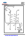
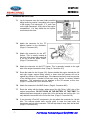
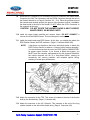
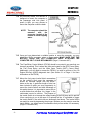
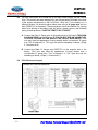
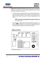
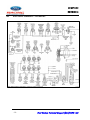
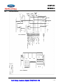
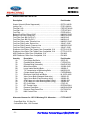
M-12071-A50 REVISION 2 Multiport EFI Engine Management Wiring Harness M-12071-A50 REVISION 2 Installation Manual TABLE OF CONTENTS Section 1.0 2.0 3.0 4.0 5.0 6.0 7.0 8.0 9.0 10.0 11.0 12.0 13.0 14.0 15.0 16.0 Topic Page Introduction ....................................................................................2 Overview .........................................................................................2 Additional Necessary Ford Sensors and Components.............. 2-3 Tools Required .............................................................................. 4 Pre-Installation of Harness and Parts ..........................................4 Harness Wire Colors and Component Locations........................ 5-6 Harness Installation....................................................................... 7-9 Wiring Connections .......................................................................10-11 Enhanced Features ....................................................................... 12-13 Initial Start Up ................................................................................ 14 Troubleshooting ............................................................................ 14-15 2-Digit EEC-IV Diagnostic Trouble Code (DTC) Definitions ...... 16-17 PCM Connector Face and Usage Chart ....................................... 18 Electrical Schematic - 5.0L Mass Air ........................................... 19 FRCM Schematic ........................................................................... 20 Miscellaneous Parts List ...............................................................21 ▬▬▬▬▬▬▬▬▬▬▬▬▬▬▬▬▬▬▬▬▬▬▬▬▬▬▬▬▬▬▬▬▬▬▬▬▬▬▬▬▬▬▬▬▬ Print Revision: Nov-2012 M-12071-A50 REVISION 2 NOTES -1- Ford Racing Technical Support (800)FORD-788 M-12071-A50 REVISION 2 1.0 INTRODUCTION This wiring harness kit is offered to allow Ford performance enthusiasts to take advantage of fuel injection technology with ease and simplicity. This harness includes numerous features intended to simplify the installation process. This harness kit is primarily intended for use on 5.0L (302) and 5.8L (351) engines, but will also fit 429/460 engines if used with the proper distributor and throttle body. You may need to purchase additional support items from Ford Racing to complete the installation of fuel injection on your engine. This will depend upon the year and type of the engine that you start with, as well as how complete your engine is. 2.0 OVERVIEW These instructions will guide you through the preparation and installation of all the required steps to equip your engine with fuel injection. Please read the instructions thoroughly before starting the installation. To insure a trouble-free installation, please read over each step that pertains to the installation procedure. If you have any questions relating to the installation of this harness, or need to know what parts may be compatible, please contact Ford Racing at (800) FORD-788. 3.0 ADDITIONAL NECESSARY FORD SENSORS AND COMPONENTS The simplicity of installing fuel injection on a Ford engine can be primarily attributed to the EFI system utilizing a Mass Air Flow meter. When the engine is properly fit with the correct size injectors and MAF meter, the engine can run properly without the need for a costly dyno tune. The following components, offered separately by your local Ford dealer, can be used to support this Ford EFI Wiring Harness. 3.1 Mass Airflow Computer for Ford----------------------------- This mass-air flow computer will work for performance engine assemblies and stock high-output engines and is compatible with C-4, C-6, and AOD transmissions; Will NOT work with computer controlled automatic transmissions. Manual Transmission - F3ZF-12A650-DB Automatic Transmission - F3ZF-12A650-FB Ford Racing Technical Support (800)FORD-788 -2- M-12071-A50 REVISION 2 (Continued) 3.2 Fuel Injector - F1ZE-9F593-C2A, 19 Lb/Hr Many Ford 302/351 fuel injected engines are factory equipped with a set of 19# Fuel Injectors, which will safely support approximately 275 HP. If you have made horsepower improvements, you will need to consider larger fuel injectors. 3.3 Mass Airflow Sensor - F1ZZ-12B579-AA If you choose a larger injector than the factory 19 lb/hr, you will need an aftermarket mass air meter calibrated for that size injector. 3.4 3.5 -3- Engine Sensors Air Charge Temp Sensor (ACT) Engine Coolant Temp Sensor (ECT) Throttle Position Sensor (TPS) Oxygen Sensor (O2), (2 Required) BARO Sensor (BP or MAP) EGR Position Sensor Motorcraft # DY-674 Motorcraft # DY-303 Motorcraft # CX-1133 Motorcraft # DY-606 Motorcraft # DY-530 Motorcraft # CX-1464 Inertia Switch (Fuel Pump Cutoff) Ford # XF3Z-9341-AA Ford Racing Technical Support (800)FORD-788 M-12071-A50 REVISION 2 4.0 TOOLS REQUIRED In addition to a common assortment of sockets, wrenches and screwdrivers, you will need the following: A. B. C. D. E. F. G. 5.0 Wire Strippers Digital Volt/Ohm Meter Solder Gun / Solder Electrical Tape / Shrink Tubing Drill Motor 2.5” Hole Saw Utility Knife PRE-INSTALLATION OF HARNESS AND PARTS 5.1 Disconnect the battery prior to doing any wiring!! 5.2 This harness has been designed to be compatible with fuel injection intake manifolds intended for use on ‘86-’93 Mustang 5.0L engines. If used on other applications, you may need to lengthen or move certain sensor leads. 5.3 Install the fuel injection lower intake manifold. Though not mandatory, it is advised to remove the upper intake if it is already installed. This will help to simplify the installation of the wiring harness onto the engine. Make sure that the ports in the lower intake manifold are covered to prevent debris from entering the engine. 5.4 Make certain that the Air Charge Temp (ACT) and Engine Coolant Temp (ECT) sensors are installed in the lower intake manifold. 5.5 Mount the Barometric Pressure (BP) sensor to the firewall behind the engine. 5.6 Identify where the EEC harness can pass through on the passenger side of the firewall. You will need to determine the proper location to cut a 2½” hole into the firewall for the harness to pass through. Check for any wires, hoses, etc. that may become damaged by the hole saw. NOTE: THIS HARNESS IS DESIGNED TO MOUNT THE COMPUTER IN THE PASSENGER SIDE KICK PANEL. 5.7 Use a center punch to mark the location of the center of the hole. By using the center punch, this will keep the drill bit from ‘walking’ while you are cutting through the firewall. 5.8 Drill the 2½” hole into the firewall. Clean any sharp edges with a file or die grinder. 5.9 The grommet will need to be cut in order to be installed onto the harness. Using a utility knife, carefully make one cut starting from the inside of the grommet and cutting outwards. It is always safest to pull the knife away from you while cutting. Ford Racing Technical Support (800)FORD-788 -4- M-12071-A50 REVISION 2 6.0 HARNESS WIRE COLORS AND CONNECTOR LOCATIONS BK = Black BR = Brown DB = Dark Blue DG = Dark Green Connector # GY = Gray LB = Light Blue LG = Light Green O = Orange Connects to PK = Pink P = Purple R = Red T = Tan W = White Y = Yellow Wire Colors 1................................ Fuel Injector #1……………………………….. R, T 2……………………… Fuel Injector #2……………………………….. R, W 3……………………… Fuel Injector #3……………………………….. R, BR/Y 4……………………… Fuel Injector #4……………………………….. R, BR/LB 5……………………… Fuel Injector #5……………………………….. R, T/BK 6……………………… Fuel Injector #6……………………………….. R, LG/O 7……………………… Fuel Injector #7……………………………….. R, T/R 8……………………… Fuel Injector #8……………………………….. R, LB 9……………………… Throttle Position Sensor (TPS)……………… BR/W, GY/R, GY/W 10……………………. Idle Air Control (IAC) Solenoid……………….R, W/LB 11……………………. Engine Coolant Temp (ECT) Sensor………. GY/ R, LG/R 12……………………. Mass Air Flow (MAF) Meter…………………. R, BK, T/LB, LB/R 13……………………. Air Charge Temp (ACT) Sensor……………. GY/R, GY 14……………………. SPOUT Connector……………………………. R, PK 15……………………. Thick Film Ignition (TFI) Module……………..O/R, T/Y, R/LG, R/LB, PK, GY/O 16……………………. Coil…………………………………………….. R/LG, T/Y 17……………………. System Ground (DIRECTLY to battery!!)….. Black 18……………………. 12V SUPPLY (USE AN INLINE FUSE!!)….. Red 19……………………. A/C Clutch Connector……………………….. BK/Y, BK/W 20……………………. Barometric Pressure (BAP) Sensor………… BR/W, GY/R, LG/BK 21……………………. Left Oxygen (O2) Sensor……………………. GY/Y, BK/W, R/BK 22……………………. Right Oxygen (O2) Sensor………………….. GY/Y, BK/W, GY/LB 23……………………. Inertia Switch Connector……………………. PK, PK/BK 24……………………. Self Test Connector…………………………. PK/LG, LB/O, GY/R, W/P 25……………………. 15-Pin Disconnect……………………………. PK/LG, R/LB, BK, T/Y PK, DG/Y, P, R/LG 26……………………. Fuse Relay Control Module (FRCM)………. ---------------------------------27……………………. 60-Pin Connector, PCM……………………... ---------------------------------28.............................. EGR Vacuum Regulator (EVR)..................... R, BR/PK 29.............................. EGR Position Sensor (EGR)......................... BR/W, GY/R, BR/LG 30.............................. Electric Fan Lead (See Page 13).................. O -5- Ford Racing Technical Support (800)FORD-788 M-12071-A50 REVISION 2 6.1 Harness Layout Ford Racing Technical Support (800)FORD-788 -6- M-12071-A50 REVISION 2 7.0 HARNESS INSTALLATION . 7.1 Lay the harness onto the lower intake manifold being careful to position it according to the layout of the engine. Fuel Injectors #1, 2, 3, and 4 are on the right (Passenger, USA) side of the engine compartment. You may attach the fuel injector connectors at this time. 7.2 Attach the connector for the TFI Module located on the distributor. (Page 6, Connector #15) 7.3 Attach the connector for the ACT Sensor. This is usually located at the front of the lower intake manifold in the top of the #5 intake runner. (Page 6, Connector #13) 7.4 Attach the connector for the ECT Sensor. This is generally located on the right side of the engine towards the front. (Page 6, Connector #11) 7.5 Route the leads for the Oxygen (O2) Sensors behind the engine towards the left and right oxygen sensors being careful to insure that the harness will not lie against any portion of the exhaust pipe. If the harness can freely touch any portion of the exhaust pipes, it should be tied back using ‘zip-ties’ or another suitable substitute. The connectors can be attached to the O2 sensors at this time. (Page 6, Connector #21 and Connector #22) 7.6 Attach the connector to the BAP Sensor. (Page 6, Connector #20) 7.7 Route the wiring with the battery leads around the left (Driver, USA) side of the engine compartment. DO NOT HOOK UP THE BATTERY AT THIS TIME! The harness has been designed to mount the Coil in the fender well on this side. You may attach the connector to the Coil at this time. (Page 6, Connector #16) 7.8 If you are using a Ford A/C compressor, you may attach the connector for it at this time. The harness should have enough slack to route the lead under the compressor and up to the connector. This will help keep it away from the fan belt. (Page 6, Connector #19) -7- Ford Racing Technical Support (800)FORD-788 M-12071-A50 REVISION 2 7.9 Route the EEC Harness 60-Pin Connector, the 9-Pin Connector, the Inertia Switch Connector, the Self Test Connector, and the FRCM Connector through the hole in the firewall referred to on Page 4 (Sections 5.6 – 5.8). Place the grommet around the harness and carefully position the groove of the grommet so that it ‘straddles’ the sheet metal in the hole of the firewall. Do NOT attach the 60-Pin Connector to the computer at this time. CAUTION: DO NOT ROUTE THE HARNESS NEAR A HEAT SOURCE, SHARP EDGES, OR MOVING PARTS. 7.10 Install the upper intake manifold and vacuum hoses. DO NOT CONNECT a vacuum line to the BARO Sensor! This must be open to atmosphere. 7.11 Install the throttle body and EGR Spacer. At this time, you should also attach the EGR Position Sensor and EVR connector. (Page 6, Connector #28 & #29) NOTE: It has been our experience that some individuals prefer to delete the EGR Position Sensor to achieve a “cleaner looking engine assembly.” You should be aware that the use of an EGR System is MANDATORY for proper engine function. If you choose to delete this system, you MUST have the computer reprogrammed for this purpose! Otherwise, the vehicle computer will run in a ‘Limp-Home Mode’, causing an excessively rich running condition, and retarded ignition timing, resulting in overall poor performance. 7.12 Attach the connector for the TPS. This sensor is located at the end of the throttle shaft on the throttle body. (Page 6, Connector #9) 7.13 Attach the connector to the IAC Solenoid. This connects at the end of the long cylinder located on the side of the throttle body. (Page 6, Connector #10) Ford Racing Technical Support (800)FORD-788 -8- M-12071-A50 REVISION 2 7.14 As previously stated, this harness is designed to mount the computer in the passenger side kick panel. If space is tight, you may choose to mount the computer under the dash. NOTE: The computer should be mounted with the connector located at the bottom to avoid trapping water. 7.15 Once you have determined a suitable location to mount the computer, you may attach the 60-Pin connector using a 10mm socket. MAKE SURE THAT THE BATTERY LEADS ARE NOT CONNECTED WHILE ATTACHING THE COMPUTER OR IT COULD BE DAMAGED! (Page 6, Connector #27) 7.16 The Fuse/Relay Control Module (FRCM) should be mounted in an area that can be easily accessed. This is where the fuses are located for the EEC Power Relay, the Fuel Pump Relay, and the Wide Open Throttle (WOT) Cutout Relay. Additionally, you will need to access the FRCM if you wish to perform a ‘Key On Engine Running’ (KOER) diagnostic test. (See Section 9.1 on Page 11 for more information on the FRCM) 7.17 Mount the fuel pump Inertia Switch somewhere on the vehicle’s body near the computer. It should be mounted upright with the RESET button at the top. A generous length of wire has been included to allow you every opportunity to mount the Inertia Switch and take advantage of this safety feature. It is important to mount this to a solid surface that will allow it to ‘trigger’ in the unfortunate event of a collision. The purpose of the Inertia Switch is to interrupt the voltage leading to the fuel pump and to prevent it from continuing to run in the case of a ruptured fuel line. It is possible to trigger the Inertia Switch if the vehicle hits an abnormally hard bump. The Inertia Switch can easily be reset by depressing the plunger. Because you may need to reset the Inertia Switch, you should mount it somewhere that you can access it if necessary. (Page 6, Connector #23) -9- Ford Racing Technical Support (800)FORD-788 M-12071-A50 REVISION 2 8.0 WIRING CONNECTIONS This harness has been designed to simplify the installation process of fuel injection. There are numerous enhancements intended to require minimal effort by the installer. With the exception of the main battery leads, all of the required harness connections have been located in a central location within a single 9-Pin Disconnect located near the computer. Additionally, all of the fuses, relays, and enhanced features have been conveniently located in the Fuse/Relay Control Module (FRCM). 8.1 Locate the Single 9-Pin Disconnect (Page 6, Connector #25). This EFI Wiring Harness kit includes a mate to this connector which includes 8 wiring pigtails. This is where you will need to make the connections for the harness. 8.2 You may use the diagram on page 11 as a reference for the following connections: A. Pin 1 (Pink/Green Wire), and Pin 2 (Pink Wire): These two wires will need to go to the “Check Engine” light. This is a mandatory connection and is required for the computer to do an initial ‘Self Test’ upon starting the engine. B. Pin 3 (Red/Blue Wire): Connect this wire to a 12V ‘START’ source, meaning that voltage is present only when the starter is cranking. This connection is used to tell the computer and the TFI module when the engine is being started, and will initiate a different strategy in the computer when voltage is applied. C. Pin 4 (Black Wire): Connect this wire to a ground source. A body ground is acceptable for this connection, though you should make sure that the area is free from rust or paint. This connection is for grounding the case of the computer and also for grounding the shielded wires leading to the TFI Module. D. Pin 6 (Green/Yellow Wire): This wire connects to the positive side of the fuel pump. Connect the negative side of the fuel pump to a ground source. If you are using a fuel pump which can draw more than 20 amps, you should use an external fuel pump relay, and use this wire as the trigger wire to that relay. E. Pin 7 (Purple Wire): If your engine is equipped with air conditioning, connect this wire to the dash control A/C switch. This wire should have power when the A/C is on. This will engage the A/C compressor clutch, and send a signal to the computer to maintain proper idle speed to compensate for the increased load which will be imposed on the engine from the A/C compressor. F. Pin 8 (Red/Green Wire): Connect this wire to a SINGLE SOURCE which will have 12 Volts when the key is in both the ‘Start’ (cranking) AND in the ‘Run’ positions. This is the primary circuit which will provide power to all of the relays and to the ignition system. G. Pin 9 (Tan/Yellow Wire): This wire is the tachometer lead. This is not a mandatory connection. Ford Racing Technical Support (800)FORD-788 - 10 - M-12071-A50 REVISION 2 8.3 The final connections to be made will be the Main Power Supply and the Ground Wire. This harness has been designed for use with the battery mounted in the front of the engine compartment on the Left (Driver, USA) side. If your battery is in a different location, you should lengthen these wires using a 10 gauge wire and run them DIRECTLY to the battery. These extensions should be soldered. By running these wires directly to the battery, this will insure a proper ground, and eliminate many potential problems. TAKE THE TIME TO DO IT RIGHT! A. Connect the Red 12 Gauge wire to the positive side of the battery THROUGH AN INLINE FUSE rated at 50 amps. IF YOU DO NOT USE AN INLINE FUSE, YOU RUN THE RISK OF FIRE SHOULD THE CIRCUIT EVER SHORT! (This wire may have the appearance of being smaller than a conventional 12 gauge wire. This is because it is ‘TXL’ type wire and the sheathing is thinner.) (Page 6, Connector #18) B. Connect the Black 12 Gauge wire DIRECTLY to the negative side of the battery. (This wire may have the appearance of being smaller than a conventional 12 gauge wire. This is because it is ‘TXL’ type wire and the sheathing is thinner.) (Page 6, Connector #17) 8.4 - 11 - 9-Pin Disconnect Layout: Ford Racing Technical Support (800)FORD-788 M-12071-A50 REVISION 2 9.0 Enhanced Features This harness has been carefully designed and developed primarily off of feedback derived from performance enthusiasts who wanted a simple, yet fully functional, wiring solution for their Street-Rods. A lot of careful thought and effort has been utilized to make this harness very simple to install. One heavily favored option is that all necessary relays and fuses have been packaged into a single location, referred to as the Fuse Relay Control Module. Quite simply, this harness is cleanest and simplest wiring harness on the market. 9.1 Fuse Relay Control Module (FRCM): This is the central location where all of the fuses and relays have been placed to minimize the bulk of wiring for a much cleaner appearance under the hood. There are a number of additional features which have been included within the FRCM: A. LED Indicators: These have been included to assist in any potential trouble shooting that may be required. When power is being passed through the relay, the LED indicator will light GREEN. B. Simple 1 Connector Hookup: With the exception of the main battery leads, all of the required harness connections have been located in a single connector. This ‘9-Pin Disconnect’ is conveniently located under the dash near the computer for ease of installation to the necessary power and ground connections. The mating connector houses the wiring leads where all of the connections are to be made. This feature allows the EFI Wiring Harness to be easily disconnected from the vehicle without disrupting the solder joints if the engine ever needs to be removed from the vehicle for any reason. C. Dual Mode Self-Test Compatibility: With previous wiring harnesses, it has been required to hook up a NEUTRAL SENSING switch if a diagnostic test procedure was desired during a Key On Engine Running (KOER) mode. This circuit has been integrated into the FRCM to eliminate the need for these additional components and to save time on wiring this circuit. Technical Tidbit: By default, the computer automatically assumes that the vehicle is in gear. If the computer cannot determine if the vehicle is in neutral, it will generate a code 67, and will not allow a diagnostic scan while the engine is running. The FRCM has integrated a circuit which can be used to simulate the vehicle being in neutral by simply depressing the yellow button located in the upper left corner of the FRCM box, labeled “PUSH TO TEST”. By depressing this button, this will complete a circuit between pin 30 and pin 46 in the computer, simulating the signal the computer would normally receive when the vehicle is in neutral. When this circuit is engaged, you will also have the ability to do a ‘Cylinder Balance Test’. For a more thorough description of diagnostic test procedures, refer to a Ford Powertrain Diagnostics/ Emissions Control manual. This circuit can be reset to default by simply turning off the key. Ford Racing Technical Support (800)FORD-788 - 12 - M-12071-A50 REVISION 2 D. Optional Electric Cooling Fan Control, By default, the factory Ford computer (PCM) has no provisions to control an electric cooling fan. However, some aftermarket ‘chip’ tuners are able to introduce this function via pin 41 at the PCM, which is normally an unused pin. If you will be using a 'chip-tuned' PCM to control an electric cooling fan, you will need to attach the 10ga Orange wire (Page 6, Item #30) to the 12V+ side of the electric cooling fan. You will also need to provide the ground cable for the fan, and it too should be a 10ga wire attached directly to the chassis. o NOTE: If the electric cooling fan being used is rated in excess of 35 amps, you should use the Orange wire to trigger an external relay for use with that fan. If you will NOT be using an electric fan, the cooling fan wire(s) can be cut back and taped off. Additionally, if the PCM has not been modified for this feature, be aware that there is no concern that the Orange wire will have any voltage present, and should not be at risk of shorting out. FRCM LAYOUT (Schematic on page 20) - 13 - Ford Racing Technical Support (800)FORD-788 M-12071-A50 REVISION 2 10.0 INITIAL START UP The following information is offered assuming you have adhered to each of the previous steps of this installation manual. This would include making certain that the main power leads are hooked up, the PCM & FRCM are connected, and all of the required connections within the ‘9 Pin Disconnect’ have been made. 10.1 Check all fluid levels, electrical and fluid connections. It is recommended to prime the oil pump to insure adequate delivery of oil to all moving parts for initial start up. 10.2 Pressurize the fuel system. This can be done by turning the key on and off several times to fully prime the system. Inspect the entire fuel system (from tank to engine) for leaks. If any leaks are found, do not proceed further until these have been corrected. 10.3 Start Engine. Check for leaks and/or noises that may indicate a problem. If no leaks or noises are present, prepare to set initial timing. 10.4 When setting the ignition timing, be certain to unplug the SPOUT connector (Page 6, Connector #14) which is located near the TFI module at the distributor. Loosen the distributor hold-down bolt. Set initial timing to factory setting of 10° BTDC. Tighten the distributor hold-down bolt, and verify timing is still correct. Reinstall the SPOUT connector; timing should advance approximately 8-10 degrees at idle. CAUTION: Be certain to run the vehicle in a well ventilated area. 11.0 TROUBLESHOOTING We have taken great strides to help insure a trouble-free installation, but If you do encounter a “No Start” condition, please check each of the following: 11.1 Check to be certain that the circuit breaker provided on the red main positive lead wire (Page 6, Connector #18) has not been tripped. This can be reset by simply pushing the black button located on the side of the circuit breaker near the copper colored terminal. 11.2 If the fuel pump does not prime, check the Inertia Switch to be certain that the “Reset Switch” is depressed. (Page 6, Connector #23) 11.3 Confirm that the green LED’s for the ”EEC Relay” and “Fuel Pump Relay” within the FRCM are lit when the key is turned on. Note: If the engine is not rotating (by either cranking or running), the fuel pump relay will only activate for 1 second when the key is first turned on. Ford Racing Technical Support (800)FORD-788 - 14 - M-12071-A50 REVISION 2 (Troubleshooting - Continued) 11.4 Verify that you have connected the black ground wire (Page 6, Connector #17) DIRECTLY to the negative side of the battery. Do NOT attach this connection to any other ground source. The entire EFI system is dependent upon this ground. Be sure to solder any splices that may have been required if this connection needed to be lengthened. 11.5 Inspect the engine for vacuum leaks. Vacuum leaks will allow air to enter the engine without being monitored by the mass air meter, which will cause the PCM to ‘think’ that the engine is receiving less air than it actually is, causing a lean condition. 11.6 Verify that you are using a quality Mass Air Flow meter. This sensor is the single most important sensor in the entire EFI system and is a common culprit of idle surge and low speed drivability problems. Ford Racing offers MAF meters that exceed OEM quality; refer to section 3.3 (on page 3) for more information. 11.7 Verify proper fuel pressure within the system. Ford EFI systems normally require 39-42 psi at the fuel rail. An IN-TANK fuel pump is highly recommended as this will help to eliminate the potential for cavitation (vapor bubbles) in the fuel supply line. If you still choose to use an externally mounted fuel pump, you should be ABSOLUTELY CERTAIN that it is gravity fed, meaning the fuel pump does not have to ‘pull’ the fuel to it. If the fuel pump creates a vacuum in the inlet of the fuel pump, the fuel can easily ‘flash’ to a vapor, creating tiny vapor bubbles within the inlet of the fuel pump. When these vapor bubbles pass through the pump to the ‘high pressure’ side, they do not go away; they are merely compressed. Once these vapor bubble are expelled through the fuel injectors, they are no longer under pressure and they will expand, displacing the fuel that is needed by the engine, and generally causing a lean condition. This problem is commonly characterized by becoming worse as the engine warms, and/or during warm weather which usually consists driving over hot pavement which reflects heat towards the fuel tank. 11.8 Perform a diagnostic test via the Self Test Connector. If you do not have an EFI Scan Tool available, it is also possible to perform this test using a simple jumper wire at the Self Test Connector. With the ignition switch in the OFF position, hook up a jumper wire from the GY/RD wire (359) in the 6-pin connector to the W/P wire (209) in the 1-pin connector. When the key is turned to the RUN position, after about 15 seconds, the 'Check Engine' light will begin to flash indicating which codes are present in the PCM. Once all codes are reported, the codes will repeat once again. These are the Key On Engine Off (KOEO) codes. Wait approximately 10 seconds after the KOEO test, and there will be a single flash, followed by another set of DTC codes which will follow. These are the 'Continuous' codes. - 15 - Ford Racing Technical Support (800)FORD-788 M-12071-A50 REVISION 2 12.0 2-Digit EEC-IV DIAGNOSTIC TROUBLE CODE (DTC) DEFINTIONS — Passenger Car DIAGNOSTIC TROUBLE CODES (DTC's) DEFINITIONS 11 - O, R, C System PASS 12 - R Cannot control rpm during KOER Self-Test high rpm check 13 - R Cannot control rpm during KOER Self-Test low rpm check 14 - C PIP circuit failure 15 - O PCM Read Only Memory (ROM) test failed 15 - C PCM Keep Alive Memory (KAM) test failed 16 - R Rpm too low to perform HO2S test 18 - R SPOUT circuit open 18 - C IDM circuit failure/SPOUT circuit grounded 19 - O Failure in PCM internal voltage 21 - O, R ECT out of Self-Test range 22 - O, R, C MAP/BARO out of Self-Test range 23 - O, R TP out of Self-Test range 24 - O, R ACT out of Self-Test range 26 - O, R MAF out of Self-Test range 29 - C Insufficient input from the Vehicle Speed Sensor (VSS) 31 - O, R, C EVP circuit below minimum voltage 32 - O, R, C EVP voltage below closed limit 33 - R, C EGR valve opening not detected 34 - O, R, C EVP voltage above closed limit 35 - O, R, C EVP circuit above maximum voltage 41 - R HO2S circuit indicates system lean (right HO2S) 41 - C No HO2S switch detected (right HO2S) 42 - R HO2S circuit indicates system rich (right HO2S) 44 - R Secondary Air Injection system inoperative (right side) 45 - R Secondary Air Injection upstream during Self-Test 46 - R Secondary Air Injection not bypassed during Self-Test 51 - O, C ECT indicated -40°C (-40°F)/circuit open 53 - O, C TP circuit above maximum voltage 54 - O, C IAT indicated -40°C (-40°F)/circuit open 56 - O, C MAF circuit above maximum voltage 61 - O, C ECT indicated 123°C (254°F)/circuit grounded 63 - O, C TP circuit below minimum voltage 64 - O, C ACT indicated 123°C (254°F)/circuit grounded Ford Racing Technical Support (800)FORD-788 - 16 - M-12071-A50 REVISION 2 66 - C MAF circuit below minimum voltage 67 - O Park/Neutral Position (PNP) switch circuit open - or A/C ON during Self-Test 77 - R Brief WOT not sensed during Self-Test/Operator error 79 - O A/C on/Defrost on during Self-Test 81 - O Secondary Air Injection Diverter (AIRD) solenoid circuit failure 82 - O Secondary Air Injection Bypass (AIRB) solenoid circuit failure 84 - O EGR Vacuum Regulator (EVR) circuit failure 85 - O Canister Purge (CANP) circuit failure 87 - O,C Fuel pump primary circuit failure 91 - R HO2S circuit indicates system lean (left HO2S) 91 - C No HO2S switching detected (left HO2S) 92 - R HO2S circuit indicates system rich (left HO2S) 94 - R Secondary Air Injection system inoperative (left side) 95 - O,C Fuel pump secondary circuit failure 96 - O,C Fuel pump secondary circuit failure 98 - R Hard fault is present - FMEM mode NO DTC's * Unable to initiate Self-Test or unable to output DTC's * DTC's NOT LISTED DTC's displayed are not applicable to the vehicle being tested KEY: O = Key On Engine Off (KOEO) R* = Engine Running (ER) C = Continuous Memory Some of the above codes can be expected and should not be a cause for concern. These are commonly referred to as 'Soft Codes' which indicates that a fault may be present, but that the PCM will not activate the 'Check Engine' light, nor will it enter into Fault Mode Engine Management (FMEM), or 'Limp Home Mode'. These codes typically include the following: 29 33 44 45 46 67 (KOER Is not possible when this code is present, See page 12, Section C) 81 82 85 87 94 95 96 * Please refer to Page 12, Section C, for help on performing Engine Running (ER) Diagnostics - 17 - Ford Racing Technical Support (800)FORD-788 M-12071-A50 REVISION 2 13.0 PCM CONNECTOR FACE AND USAGE CHART Ford Racing Technical Support (800)FORD-788 - 18 - M-12071-A50 REVISION 2 14.0 ELECTRICAL SCHEMATIC - 5.0L Mass Air - 19 - Ford Racing Technical Support (800)FORD-788 M-12071-A50 REVISION 2 15.0 FRCM Schematic Ford Racing Technical Support (800)FORD-788 - 20 - M-12071-A50 REVISION 2 16.0 MISCELLANEOUS PARTS LIST Description Part Number Starter Solenoid (Diode Suppressed) ……………………………….. E9TZ-11450-B Ignition Coil ...………………………………………………………….. E73Z-12029-A Fuel Rail, 5.0L …………………………………………………………. F2ZZ-9F792-AS Fuel Rail, 5.8L …………………………………………………………. F2TZ-9F792-C Fuel Filter ………………………………………………………………. E7DZ-9155-A Barbed Fuel Filter Fitting (5/16”) ……………………………………... N806187-S190 Barbed Fuel Filter Fitting (3/8”) ………………………………………. N806796-S190 Fuel Filter Duck Bill Clip (5/16”) ……………………………………… N802239-S Fuel Filter Duck Bill Clip (3/8”) ……………………………………….. N802241-S Fuel Line Fitting, male, Pressure Line ………………………………. N806207-S190 Fuel Line Fitting, male, Return Line …………………………………. 390417-S190 Fuel Line Fitting, female, Pressure Line …………………………….. N806205-S190 Fuel Line Fitting, female, Return Line ……………………………….. 390417-S190 Distributor, Non Roller (Flat Tappet) Cam Compatible, 5.0L ……… E5TZ-12127-B Distributor, Non Roller (Flat Tappet) Cam Compatible, 5.8L ……… E7TZ-12127-D MSD Distributor, Roller Cam Compatible, 5.0L …………………….. PN 8456 MSD Distributor, Roller Cam Compatible, 5.8L …………………….. PN 8452 Quantity (4) (6) (6) (4) (12) (4) (4) (1) (6) (6) (4) (2) (4) (1) (6) (3) (1) Description Part Number Fuel Injector Rail Bolts ……………………………….. 56073-S2 Flywheel Bolts (Manual) ……………………………... F1ZZ-6379-A Flywheel Bolts (Automatic) ………………………….. D2AZ-6379-B Motor Mount Bolts ……………………………………. 391099-S100 Lower Intake Manifold Bolts …………………………. 388058-S T-5 Transmission to Bellhousing Bolts ……………...N605935-S2 Cylinder Head Smog Plugs …………………………. F4ZZ-6E086-A Distributor Hold-Down and Bolts ……………………. M-12270-A302 Valve Cover Bolts (Stamped Steel style) …………...390819-S2 Valve Cover Bolts (Cast Aluminum style) ………….. 390820-S8 GT40 Upper to Lower Mounting Bolts (Short) …….. 390395-S32 GT40 Upper to Lower Mounting Bolts (Long) ……... 390658-S8 EFI Cover Bolts ……………………………………….. 57357-S2 EFI Throttle Cable ……………………………………. E6ZZ-9A758-A Pressure Plate Bolts …………………………………..N602549-S51M Pressure Plate Dowel Pins ………………………….. D1FZ-6397-B K&N Conical Filter ……………………………………. RU-3130 Alternator Harness for 1987-93 Mustang 5.0L Alternator ……... F3TZ-14305-F - Green/Red Wire, 12V Key On - Yellow/White Wire, 12V Constant - 21 - Ford Racing Technical Support (800)FORD-788 M-12071-A50 REVISION 2 NOTES Ford Racing Technical Support (800)FORD-788 - 22 - Print Revision: Nov-2012