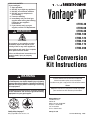
1
FOR YOUR SAFETY If you smell gas: 1. Open windows. 2. DO NOT try to light any appliance. 3. DO NOT use electrical switches. 4. DO NOT use any telephone in your building. 5. Leave the building. 6. Immediately call your local gas supplier after leaving the building. Follow the gas suppliers instructions. 7. If you cannot reach your gas supplier, call the Fire Department. Vantage NP ® CTHN-40 CTHN-60 CTHN-80 CTHN-100 CTHN-125 CTHN-150 CTHN-175 CTHN-200 WARNING Fire Hazard Do not store or use gasoline or other flammable vapors and liquids in the vicinity of this or any other appliance. Some objects will catch fire or explode when placed close to heater. Failure to follow these instructions can result in death, injury or property damage. Fuel Conversion Kit Instructions WARNING Improper installation, adjustment, alteration, service or maintenance can result in death, injury or property damage. Read the Installation, Operation and Service Manual thoroughly before installing or servicing this equipment. Installation must be done by a contractor qualified in the installation and service of gas-fired heating equipment or your gas supplier. Installer Please take the time to read and understand these instructions prior to any installation. Installer must give a copy of this manual to the owner. Owner Keep this manual in a safe place in order to provide your serviceman with necessary information. Roberts-Gordon, LLC 1250 William Street P.O. Box 44 Buffalo, New York 14240-0044 Telephone: 716.852.4400 Fax: 716.852.0854 Toll Free: 800.828.7450 Quality in Any Language™ © Copyright 2006 Roberts-Gordon, LLC www.rg-inc.com P/N 252101NA Orig. 10/06 TABLE OF CONTENTS SECTION 1: Heater Safety...................................................... 1 SECTION 2: Installer Responsibility ..................................... 2 2.1 Wall Tag ....................................................................... 2 2.2 Corrosive Chemicals.................................................... 2 2.3 National Standards and Applicable Codes .................. 2 SECTION 3: For Natural to Propane Conversions Only....... 3 3.1 Contents of Fuel Conversion Kits (Natural to Propane).......3 SECTION 4: For Propane to Natural Conversions Only....... 4 4.1 Contents of Fuel Conversion Kits (Propane to Natural).......4 SECTION 5: Fuel Conversion Instructions ........................... 5 5.1 Burner Removal........................................................... 5 5.2 Door Assembly Removal ............................................. 5 5.3 Burner Cup Assembly Removal and Reassembly ......................................................... 7 5.4 Regulator Spring Replacement.................................... 7 5.5 Inlet Gas Pressure Checks .......................................... 8 5.6 Adjust Regulator .......................................................... 8 5.7 Burner Conversion Label Information ........................ 11 5.8 Attach Burner Conversion Label................................ 11 SECTION 6: Critical Considerations.................................... 12 6.1 Required Clearances to Combustibles....................... 12 SECTION 7: Operation and Maintenance............................ 17 7.1 Sequence of Operation .............................................. 17 7.2 To Shut Off Heater...................................................... 17 7.3 To Start Heater ........................................................... 17 7.4 Pre-Season Maintenance and Annual Inspection....... 17 7.5 Maintenance Checklist.........................................................18 SECTION 8: The ROBERTS GORDON® VANTAGE® NP Warranty ........................................................... 21 © 2006 Roberts-Gordon, LLC All rights reserved. No part of this work covered by the copyrights herein may be reproduced or copied in any form or by any means - graphic, electronic, or mechanical, including photocopying, recording, taping or information storage and retrieval systems - without the written permission of Roberts-Gordon, LLC. Printed in U.S.A. TABLE OF FIGURES Figure 1: Conversion Kit Regulator Installation in Valve (Natural to Propane)................................................... 3 Figure 2: Conversion Kit Regulator Installation in Valve (Propane to Natural)................................................... 4 Figure 3: VANTAGE® NP Burner Assembly Overview .............. 5 Figure 4: Burner (external view from below) ............................. 6 Figure 5: Burner, Top View (internal assembly) ........................ 6 Figure 6: Pressure Regulator.................................................... 7 Figure 7: Burner, Side View (internal assembly) ....................... 8 Figure 8: Manometer Reading (Gas Pressure) ......................... 9 Figure 9: Manometer Reading (Differential Reading).............. 10 Figure 10: Label P/N 91039400 .............................................. 11 Figure 11: Standard Reflector.................................................. 13 Figure 12: One Side Reflector................................................. 13 Figure 13: Two Side Reflectors................................................ 13 Figure 14: 45° Tilt Reflector..................................................... 14 Figure 15: U-Tube, Standard Reflector.................................... 14 Figure 16: U-Tube, 45° ............................................................ 14 Figure 17: U-Tube, Opposite 45° Reflector.............................. 15 Figure 18: 2-Foot Deco Grille, 1-Foot Deco Grille and Protective Grille............................................... 15 Figure 19: Lower Clearance Shield ......................................... 15 Figure 20: Venting ................................................................... 16 SECTION 1: HEATER SAFETY SECTION 1: HEATER SAFETY Your Safety is Important to Us! This symbol is used throughout the manual to notify you of possible fire, electrical or burn hazards. Please pay special attention when reading and following the warnings in these sections. Installation, service and annual inspection of heater must be done by a contractor qualified in the installation and service of gas-fired heating equipment. Read this manual carefully before installation, operation or service of this equipment. Due to the nature of gas conversions, it is important you use the correct conversion kit for the heater model and gas you are converting to. Use only genuine ROBERTS GORDON® conversion kits. This heater is designed for heating nonresidential indoor spaces. Do not install in residential spaces. These instructions, the layout drawing, local codes and ordinances, and applicable standards that apply to gas piping, electrical wiring, venting, etc., must be thoroughly understood before proceeding with the installation. Thin sheet metal parts, such as the reflector portion of the heater and the various venting components, have sharp edges. To prevent injury, the use of work gloves is recommended. The use of gloves will also prevent the transfer of body oils from the hands to the surface of the reflector. WARNING Explosion Hazard Turn off gas supply to heater before service or maintenance. Failure to follow these instructions can result in death, injury or property damage. WARNING Electrical Shock Hazard Disconnect electrical power before service or maintenance. Failure to follow these instructions can result in death or electrical shock. Before installation, check that local distribution conditions, nature of gas and pressure, and adjustment of the appliance are compatible. For additional copies of the VANTAGE® NP Installation, Operation and Service Manual, please contact Roberts-Gordon. 1 VANTAGE® NP FUEL CONVERSION INSTRUCTIONS SECTION 2: INSTALLER RESPONSIBILITY The installer is responsible for the following: • To install the heater, as well as the gas and electrical supplies, in accordance with applicable specifications and codes. Roberts-Gordon recommends the installer contact a local Building Inspector or Fire Marshal for guidance. • To use the information given in a layout drawing and in the manual together with the cited codes and regulations to perform the installation. • To install the heater in accordance with the clearances to combustibles. • To furnish all needed materials not furnished as standard equipment. • To plan location of supports. • To provide access to burners for servicing on all sides, for burner removal. • To provide the owner with a copy of this installation, operation and service manual. • To never use heater as support for ladder or other access equipment and never hang or suspend anything from heater. • To safely and adequately install heater using materials with a minimal working load of 75 lbs. (33 kg). • To ensure there is adequate air circulation around the heater and to supply air for combustion, ventilation and distribution in accordance with local codes. 2.1 Wall Tag A laminated wall tag is available for the heater as a permanent reminder of the safety instructions and the importance of the required clearances to combustibles. Please contact Roberts-Gordon or your ROBERTS GORDON® independent distributor to obtain the wall tag. Affix the tag by peeling off the backing of the adhesive strips on the rear surface and position the tag on a wall near the heater (e.g. thermostat or ROBERTS GORDON® Controller). A copy of the wall tag (P/N 91037912) is illustrated on the back cover. For an immediate solution, you may affix this copy on the wall near the heater. Know your model number and installed configuration. Model number and installed configuration are found on the burner and in the Installation, Operation and Service Manual. See Page 13, Figure 11 through Page 14, Figure 16. Write the proper clearance dimensions in permanent ink according to your 2 model number and configuration in the open spaces on the tag. 2.2 Corrosive Chemicals CAUTION Do not use heater in an area containing corrosive chemicals. Avoid the use of corrosive chemicals to ensure a longer life of the burner, tubing and other parts. Failure to follow these instructions can result in property damage. Roberts-Gordon cannot be responsible for ensuring that all appropriate safety measures are undertaken prior to installation; this is entirely the responsibility of the installer. It is essential that the contractor, the sub-contractor, or the owner identifies the presence of combustible materials, corrosive chemicals or halogenated hydrocarbons* anywhere in the premises. * Halogenated Hydrocarbons are a family of chemical compounds characterized by the presence of halogen elements (fluorine, chlorine, bromine, etc.). These compounds are frequently used in refrigerants, cleaning agents, solvents, etc. If these compounds enter the air supply of the burner, the life span of the heater components will be greatly reduced. An outside air supply must be provided to the burners whenever the presence of these compounds is suspected. Warranty will be invalid if the heater is exposed to halogenated hydrocarbons. 2.3 National Standards and Applicable Codes All Appliances must be installed in accordance with the latest revision of the applicable standards and national codes. This refers also to the electric, gas and venting installation. Note: Additional standards for installations in Public Garages, Aircraft Hangars, etc. may be applicable. In Canada, the conversion shall be carried out in accordance with the requirements of the provincial authorities having jurisdiction and in accordance with the requirements of the CAN-B149.1 and CAN/CGA B149.1 and B149.2 Installation Codes for Gas Burning Appliances. SECTION 3: FOR NATURAL TO PROPANE CONVERSIONS ONLY SECTION 3: FOR NATURAL TO PROPANE CONVERSIONS ONLY FIGURE 1: Conversion Kit Regulator Installation in Valve (Natural to Propane) WARNING This appliance has been converted to _______ fuel. Fire Hazard Orifice: Manifold Pressure: Check conversion kit part number before proceeding. Input: Kit part number must match the corresponding model number. Cet appareil a été converti au: Failure to follow these instructions can result in death, injury or property damage. Injecteur: Pression à la tubulure d'alimentation: Débit calorifique: Sping Kit: P/N 90032600 © Printed in the U.S.A./Imprimé aux Etats-Unis P/N 91039400 Cap Screw (black) Gas Conversion Label: P/N 91039400 O Ring (black) Pressure Regulator Adjusting Screw (white) Spring (red) Pressure Regulator Housing Orifice: P/N (See Table Below) 3.1 Contents of Fuel Conversion Kits (Natural to Propane) All kits include this manual (P/N 252101NA) and the VANTAGE® NP Installation, Operation and Service Manual (P/N 152101NA). Kit Number Model Orifice P/N Label Spring Kit CTHN040NP CTHN-40 91910473 91039400 90032600 CTHN060NP CTHN-60 91910444 91039400 90032600 CTHN080NP CTHN-80 91910506 91039400 90032600 CTHN100NP CTHN-100 91910433 91039400 90032600 CTHN125NP CTHN-125 91910490 91039400 90032600 CTHN150NP CTHN-150 91910482 91039400 90032600 CTHN175NP CTHN-175 91910427 91039400 90032600 CTHN200NP CTHN-200 91910423 91039400 90032600 3 VANTAGE® NP FUEL CONVERSION INSTRUCTIONS SECTION 4: FOR PROPANE TO NATURAL CONVERSIONS ONLY FIGURE 2: Conversion Kit Regulator Installation in Valve (Propane to Natural) WARNING This appliance has been converted to _______ fuel. Fire Hazard Orifice: Manifold Pressure: Check conversion kit part number before proceeding. Input: Kit part number must match the corresponding model number. Cet appareil a été converti au: Failure to follow these instructions can result in death, injury or property damage. Injecteur: Pression à la tubulure d'alimentation: Débit calorifique: Sping Kit: P/N 90032700 © Printed in the U.S.A./Imprimé aux Etats-Unis P/N 91039400 Cap Screw (silver) Gas Conversion Label: P/N 91039400 O Ring (black) Pressure Regulator Adjusting Screw (white) Spring (silver) Pressure Regulator Housing Orifice: P/N (See Table Below) 4.1 Contents of Fuel Conversion Kits (Propane to Natural) All kits include this manual (P/N 252101NA) and the VANTAGE® NP Installation, Operation and Service Manual (P/N 152101NA). 4 Kit Number Model Orifice P/N Label Spring Kit CTHN040PN CTHN-40 91910433 91039400 90032700 CTHN060PN CTHN-60 91910429 91039400 90032700 CTHN080PN CTHN-80 91910421 91039400 90032700 CTHN100PN CTHN-100 91910416 91039400 90032700 CTHN125PN CTHN-125 91910409 91039400 90032700 CTHN150PN CTHN-150 91910403 91039400 90032700 CTHN175PN CTHN-175 91910496 91039400 90032700 CTHN200PN CTHN-200 91910495 91039400 90032700 SECTION 5: FUEL CONVERSION INSTRUCTIONS SECTION 5: FUEL CONVERSION INSTRUCTIONS NOTE: In order to convert the CTHN-Series heater for alternate gas, you must access both sides of the burner. It may be easier to remove the burner to a workbench; however, it can be converted in place. If you are converting the burner in place, skip to Step 5.2. Step 5.1 Burner Removal 1. Turn off gas supply valve, disconnect gas from burner. 2. Turn off power supply and disconnect wires from burner. 4. If outside air is installed, disconnect. 5. Remove the bolts which hold the burner on the transition tube using a 1/2" wrench. 6. Remove the burner. See Figure 3. 7. Save the gasket (P/N 02568200) or re-install a new one after conversion. Step 5.2 Door Assembly Removal Remove thumb screws and set aside. See Page 6, Figure 4. 3. Unplug thermostat wires from burner. FIGURE 3: VANTAGE® NP Burner Assembly Overview Gasket S-Hook Burner Tube Burner Lock Washer Bolt (Torque 120 in/lb 13.56 Nm) 5 VANTAGE® NP FUEL CONVERSION INSTRUCTIONS FIGURE 4: Burner (external view from below) Control Side Door Air Side Door Vantage NP ® by ROBERTS GORDON (3) Thumb Screws Install Label Here P/N 91039400 (2) Thumb Screws FIGURE 5: Burner, Top View (internal assembly) Motor and Blower Assembly Blower Inlet Gasket Door Switch Burner Cup Orifice Air Adapter Collar Gas Valve Hot Surface Igniter Manifold 6 SECTION 5: FUEL CONVERSION INSTRUCTIONS Step 5.3 Burner Cup Assembly Removal and Reassembly 1. Remove the electrode: Remove the electrode with a 1/4" nutdriver or phillips (+) screwdriver. 2. Remove the air side door. Remove the three thumb screws and set the door aside. See Page 6, Figure 4. 3. Remove the burner cup. Unscrew the burner cup and set aside. See Page 6, Figure 5. 4. Remove and replace the gas orifice. Use a 1/2" open end wrench (spanner) to remove the orifice. Apply a small amount of pipe sealant to the threads of the replacement orifice. Be aware that over application of sealant may cause blockage of the orifice. Insert and tighten the replacement orifice. CAUTION: Do not over-tighten the orifice. The torque value for the orifice is 15 in/lbs; contact your factory representative for more details. 5. Be sure gas supply to heater is off. 6. Replace the burner cup. Insure the large external tooth washer is in place then tighten the burner cup. 7. Replace the air side door. 8. Replace the electrode. FIGURE 6: Pressure Regulator Cap Screw (black) O Ring (black) Pressure Regulator Adjusting Screw (white) Spring (Silver for Natural Gas) (Red for Propane Gas) Pressure Regulator Housing 5. If the burner is removed, re-install the gasket and the burner on the transition tube by inserting lockwashers and bolts, torque to 120 in/lbs. Reconnect outside air, gas and electrical supplies. For proper installation procedures, see Venting, Gas Piping and Electrical Sections of the VANTAGE® NP Installation, Operation and Service Manual (P/N 152101NA) included in this Conversion Kit. Step 5.4 Regulator Spring Replacement See Figure 6. 1. Replace the regulator spring. Using a flat head screwdriver, remove the cap from the regulator adjusting screw, remove the screw and remove and replace the spring. 2. NOTE: Silver spring for Natural, red spring for Propane. 3. See Page 3, Section 3 and Page 4, Section 4 to verify spring kit components. 4. Replace the adjusting screw and turn down approximately 1/2". 7 VANTAGE® NP FUEL CONVERSION INSTRUCTIONS FIGURE 7: Burner, Side View (internal assembly) Pressure Switch Gas Valve Tube Gasket Transformer Step 5.5 Inlet Gas Pressure Checks The gas inlet pressure to the heater must be checked as follows: 1. Turn off electrical supply to heater. 2. Turn off gas supply to heater. 3. Remove the plug at the valve inlet and install a test tap and hose. Connect the hose to a liquid filled manometer. See Page 9, Figure 8. 4. Turn on gas supply to heater. 5. The manometer should read a maximum gas pressure of 14.0" wc for Natural or LP gas. 6. Turn on electrical supply to heater. 7. With heater in operation, manometer should read a minimum inlet pressure of 4.5" wc for Natural gas or 11.0" wc for LP gas. 8. If the required maximum and minimum pressures are not obtained, the main gas supply pressure to the heater must be adjusted as necessary. 9. Turn off main gas supply to heater. 10.Turn off electrical supply to heater. 11. Remove manometer and insert pipe plug into valve. 12.Turn on main gas supply to heater. 13.Leak test plug in tapping using soap solution. 14.Turn on electrical supply to heater. 8 Step 5.6 Adjust Regulator 1. Using a 3/16" hex key, remove the plug at the valve outlet and install a test tap and hose. Connect the hose to a liquid filled manometer. See Page 9, Figure 8. NOTE: Insure differential box pressure is .75" (hot) per Section 17 of the VANTAGE® NP Installation, Operation and Service Manual (P/N 152101NA). See Page 10, Figure 9. 2. Turn on gas and power, turn up thermostat. 3. When unit comes on; adjust the regulator by turning the adjusting screw to set the pressure to: Natural: 3.5" wc Propane: 10.5" wc 4. Turn off power and gas. 5. Remove test tap and replace plug at the valve outlet. Replace O ring and cap screw. SECTION 5: FUEL CONVERSION INSTRUCTIONS FIGURE 8: Manometer Reading (Gas Pressure) WARNING Electrical Shock Hazard Disconnect electrical power and gas supply before servicing. This appliance must be connected to a properly grounded electrical source. Failure to follow these instructions can result in death or electrical shock. Valve Inlet Valve Outlet Regulator Top View of Heater Manometer 6 5 4 3 2 1 0 1 2 3 4 5 6 Natural 3.5" wc 6 5 4 3 2 1 0 1 2 3 4 5 6 10.5" wc Propane 9 VANTAGE® NP FUEL CONVERSION INSTRUCTIONS FIGURE 9: Manometer Reading (Differential Reading) WARNING Electrical Shock Hazard Disconnect electrical power and gas supply before servicing. This appliance must be connected to a properly grounded electrical source. Failure to follow these instructions can result in death or electrical shock. Remove Cap Attach Manometer Hose Remove Cap Attach Manometer Hose 6 5 4 3 .75" wc 2 1 0 1 2 3 4 5 6 10 Manometer SECTION 5: FUEL CONVERSION INSTRUCTIONS FIGURE 10: Label P/N 91039400 Enter Data for Natural to Propane Conversions Enter Data for Propane to Natural Conversions Model Propane Orifice Size Model Natural Orifice Size CTHN-40 1.8 mm CTHN-40 #33 CTHN-60 #44 CTHN-60 #29 CTHN-80 2.6 mm CTHN-80 #21 CTHN-100 #33 CTHN-100 #16 CTHN-125 1/8” CTHN-125 #9 CTHN-150 3.4 mm CTHN-150 #3 CTHN-175 #27 CTHN-175 A CTHN-200 #23 CTHN-200 E Propane This appliance has been converted to _______ fuel. Natural Orifice: 10.5" wc From Serial Plate Manifold Pressure: 3.5" wc Input: From Serial Plate Cet appareil a été converti au: Injecteur: Pression à la tubulure d'alimentation: Débit calorifique: © Printed in the U.S.A./Imprimé aux Etats-Unis P/N 91039400 Step 5.7 Burner Conversion Label Information Print the requested information in the fields of the burner conversion label as shown in Figure 10. Step 5.8 Attach Burner Conversion Label 1. Attach the small yellow gas label (included in conversion kit) to the gas valve. Attach the conversion label (P/N 91039400) to the burner housing. See Page 6, Figure 4. 2. Replace all access doors and secure with thumbscrews. 11 VANTAGE® NP FUEL CONVERSION INSTRUCTIONS SECTION 6: CRITICAL CONSIDERATIONS 6.1 Required Clearances to Combustibles Clearances are the required distances that combustible objects must be away from the heater to prevent serious fire hazards. Combustibles are materials, which may catch on fire and include common items such as wood, paper, rubber, fabric, etc. Maintain clearances to combustibles at all times for safety. Clearances for all heater models are located on the burner of the heater and on Page 13, Figure 11 through Page 14, Figure 16 in this manual. Check the clearances on each burner for the model heater being installed to make sure the product is suitable for your application and the clearances are maintained. Read and follow the safety guidelines below: • Keep gasoline or other combustible materials including flammable objects, liquids, dust or vapors away from this heater or any other appliance. • Maintain clearances from heat sensitive material, equipment and workstations. • Maintain clearances from vehicles parked below the heater. • Maintain clearances from swinging and overhead doors, overhead cranes, vehicle lifts, partitions, storage racks, hoists, etc. • In locations used for the storage of combustible materials, signs must be posted to specify the maximum permissible stacking height to maintain required clearances from the heater to the combustibles. Signs must be posted adjacent to • the heater thermostat. In the absence of a • thermostat, signs must be posted in a conspicuous location. • Consult local Fire Marshal, Fire Insurance Carrier or other authorities for approval of proposed installation when there is a possibility of exposure to combustible airborne materials or vapors. • Hang heater in accordance to the minimum suspension requirements in the heater’s Installation, Operation and Service manual. • If the radiant tubes must pass through the building structure, be sure that adequate sleeving and fire stop is installed to prevent scorching and/or fire hazard. 12 WARNING Fire Hazard Some objects will catch fire or explode when placed close to heater. Keep all flammable objects, liquids and vapors the required clearances to combustibles away from heater. Failure to follow these instructions can result in death, injury or property damage. SECTION 6: CRITICAL CONSIDERATIONS NOTE: 1. All dimensions are from the surfaces of all tubes, couplings and elbows. 2. Clearances B, C and D can be reduced by 50% after 25' (7.5 m) of tubing downstream from where the burner and burner tube connect. FIGURE 11: STANDARD REFLECTOR Model A (inches) B C CTHN-40 5 20 41 20 13 51 104 51 CTHN-60 5 27 51 27 13 69 130 69 CTHN-80 5 30 58 30 13 76 147 76 CTHN-100 5 32 60 32 13 81 152 81 CTHN-125 5 35 65 35 13 89 165 89 CTHN-150 5 39 71 39 13 99 180 99 CTHN-175 8 44 74 44 20 112 188 112 CTHN-200 8 47 76 47 20 119 193 119 Model A (inches) B C D A CTHN-40 5 6 46 35 13 15 117 88 CTHN-60 5 6 55 44 13 15 140 110 CTHN-80 5 6 64 49 13 15 163 123 CTHN-100 5 6 66 51 13 15 168 128 CTHN-125 5 6 69 58 13 15 175 145 CTHN-150 5 6 75 60 13 15 191 150 CTHN-175 8 6 77 68 20 15 196 170 CTHN-200 8 6 79 70 20 15 201 175 Model A (inches) B C D A CTHN-40 5 16 47 16 13 41 119 41 CTHN-60 5 18 56 18 13 46 142 46 CTHN-80 5 21 65 21 13 53 165 53 CTHN-100 5 23 68 23 13 58 173 58 CTHN-125 5 26 73 26 13 66 185 66 CTHN-150 5 30 76 30 13 76 193 76 CTHN-175 8 32 88 32 20 81 224 81 CTHN-200 8 33 90 33 20 84 229 84 D A (centimeters) B C D FIGURE 12: ONE SIDE REFLECTOR A C B D (centimeters) B C D FIGURE 13: TWO SIDE REFLECTORS A C B D (centimeters) B C D 13 VANTAGE® NP FUEL CONVERSION INSTRUCTIONS NOTE: 1. All dimensions are from the surfaces of all tubes, couplings and elbows. 2. Clearances B, C and D can be reduced by 50% after 25' (7.5 m) of tubing downstream from where the burner and burner tube connect. FIGURE 14: 45° TILT REFLECTOR Model A (inches) B C CTHN-40 8 4 35 43 20 10 89 109 CTHN-60 8 4 45 45 20 10 114 114 CTHN-80 9 4 54 55 23 10 137 140 CTHN-100 10 4 57 56 25 10 145 142 CTHN-125 10 4 63 58 25 10 160 147 CTHN-150 10 4 66 61 25 10 168 155 CTHN-175 10 4 69 68 25 10 175 173 CTHN-200 10 4 73 71 25 10 185 180 D A (centimeters) B C D FIGURE 15: U-TUBE, STANDARD REFLECTOR CTHN-40 (inches) A B C D - UNAPPROVED - (centimeters) A B C D - UNAPPROVED - CTHN-60 5 27 56 19 13 69 142 48 CTHN-80 5 30 61 20 13 76 155 51 CTHN-100 5 32 63 20 13 81 160 51 CTHN-125 5 35 66 20 13 89 168 51 CTHN-150 5 39 73 21 13 99 185 53 CTHN-175 8 44 75 26 20 112 191 66 CTHN-200 8 47 76 30 20 119 193 76 Model FIGURE 16: U-TUBE, 45° CTHN-40 (inches) A B C D - UNAPPROVED - (centimeters) A B C D - UNAPPROVED - CTHN-60 8 4 47 40 20 10 119 102 CTHN-80 8 4 54 46 20 10 137 117 CTHN-100 8 4 57 48 20 10 145 122 CTHN-125 8 4 63 53 20 10 160 135 CTHN-150 8 4 66 56 20 10 168 142 CTHN-175 8 4 69 59 20 10 175 150 CTHN-200 8 4 73 63 20 10 185 160 Model A B D C 14 SECTION 6: CRITICAL CONSIDERATIONS NOTE: 1. All dimensions are from the surfaces of all tubes, couplings and elbows. 2. Clearances B, C and D can be reduced by 50% after 25' (7.5 m) of tubing downstream from where the burner and burner tube connect. FIGURE 17: U-TUBE, OPPOSITE 45° REFLECTOR CTHN-40 (inches) A B C D - UNAPPROVED - (centimeters) A B C D - UNAPPROVED - CTHN-60 8 45 45 10 20 114 114 25 CTHN-80 9 55 54 10 23 140 137 25 CTHN-100 10 56 57 10 25 142 145 25 CTHN-125 10 58 63 10 25 147 160 25 CTHN-150 10 61 66 20 25 155 168 51 CTHN-175 10 68 69 20 25 173 175 51 CTHN-200 10 71 73 20 25 180 185 51 Model A B D C FIGURE 18: 2-FOOT DECO GRILLE, 1-FOOT DECO GRILLE AND PROTECTIVE GRILLE (inches) (centimeters) Model A B C D A B C A C B D D CTHN-40 5 20 41 20 13 51 104 51 CTHN-60 5 27 51 27 13 69 130 69 CTHN-80 5 30 58 30 13 76 147 76 CTHN-100 5 32 60 32 13 81 152 81 CTHN-125 5 35 65 35 13 89 165 89 CTHN-150 5 39 71 39 13 99 180 99 CTHN-175 8 44 74 44 20 112 188 112 CTHN-200 8 47 76 47 20 119 193 119 Model A (inches) B C D A CTHN-40 5 25 22 25 13 64 56 64 CTHN-60 5 30 27 30 13 76 69 76 CTHN-80 5 37 37 37 13 94 94 94 CTHN-100 5 39 39 39 13 99 99 99 CTHN-125 5 41 41 41 13 104 104 104 CTHN-150 5 43 50 43 13 109 127 109 FIGURE 19: LOWER CLEARANCE SHIELD* A C B D (centimeters) B C CTHN-175 - UNAPPROVED - - UNAPPROVED - CTHN-200 - UNAPPROVED - - UNAPPROVED - D *When installed in the first 10' (3 m). 15 VANTAGE® NP FUEL CONVERSION INSTRUCTIONS NOTE: 1. All dimensions are from the surfaces of all tubes, couplings and elbows. 2. Clearances B, C and D can be reduced by 50% after 25' (7.5 m) of tubing downstream from where the burner and burner tube connect. FIGURE 20: VENTING A Unvented Radiant Tubes Vented 16 E Vent Pipes F Model A (inches) E CTHN-40 14 18 18 36 46 46 CTHN-60 14 18 18 36 46 46 CTHN-80 20 24 18 51 61 46 CTHN-100 20 24 18 51 61 46 CTHN-125 20 24 18 51 61 46 CTHN-150 20 30 18 51 76 46 CTHN-175 20 30 18 51 76 46 CTHN-200 20 30 18 51 76 46 F A (centimeters) E F SECTION 7: OPERATION AND MAINTENANCE SECTION 7: OPERATION AND MAINTENANCE 7.3 To Start Heater Turn gas valve and electric power OFF and wait five minutes for unburned gases to vent from heater. Turn ON main gas valve. Turn ON electric power. Set thermostat to desired temperature, burner should light automatically. 7.4 Pre-Season Maintenance and Annual Inspection To ensure your safety and years of trouble-free operation of the heating system, service and annual inspections must be done by a contractor qualified in the installation and service of gas-fired heating equipment. The CTHN-Series series heater is equipped with a direct spark ignition system. 7.1 Sequence of Operation 1. Turn the thermostat up. When the thermostat calls for heat, the pump will start immediately. After a small delay, the burners will begin their ignition sequence, 45 seconds later, sparking will begin at the electrode. Upon sparking of the electrodes, the gas valve is energized. 2. The flame will be sensed by the flame sensing rod and the electrode is de-energized. 3. If a flame is detected, the gas valve remains open. When the call for heat is satisfied, the burner shuts off. On CTHN-Series systems equipped with the optional ROBERTS GORDON® controllers, the pump will continue operation for a post-purge period of two minutes. Disconnect gas and electric supplies before performing service or maintenance. Allow heater to cool before servicing. Before every heating season, a contractor qualified in the installation and service of gas-fired heating equipment must perform a thorough safety inspection of the heater. For best performance, the gas, electrical, thermostat connections, tubing, venting, suspensions and overall heater condition are some of the areas requiring inspection. NOTE: Gas flow and burner ignition are among the first things that should be inspected. Please see Page 18, Section 7.5 for suggested items to inspect. 4. If no flame is detected, the gas valve is closed on the module and a purge period begins. After the purge, the module sparks, and there is a second trial for ignition. If flame is still not established, a third purge, and trial cycle begins. After 3 trials, the module will lockout until reset. Reset is accomplished by removing power from the module for at least 5 seconds (thermostat cycle required). 7.2 To Shut Off Heater Set thermostat to lowest setting. Turn OFF electric power to heater. Turn OFF manual gas valve in the heater supply line. 17 VANTAGE® NP FUEL CONVERSION INSTRUCTIONS 7.5 Maintenance Checklist WARNING Explosion Hazard Service and annual inspection must be done by a contractor qualified in the installation and service of gas-fired heating equipment or your gas supplier. Turn off gas and electrical supplies before performing service or maintenance. Failure to follow these instructions can result in death, injury or property damage. The Vicinity of the Heater Installation Code and Annual Inspections: All installations and service of ROBERTS GORDON® products must be performed by a contractor qualified in the installation and service of products sold and supplied by Roberts-Gordon and conform to all requirements set forth in the ROBERTS GORDON® manuals and all applicable governmental authorities pertaining to the installation, service and operation of the equipment. To help facilitate optimum performance and safety, Roberts-Gordon recommends that a qualified contractor annually inspect your ROBERTS GORDON® products and perform service where necessary, using only ROBERTS GORDON® replacement parts. Do not store or use flammable objects, liquids or vapors near the heater. Immediately remove these items if they are present. See Page 12, Section 6. Vehicles and Other Objects Maintain the clearances to combustibles. Do not hang anything from, or place anything on, the heater. Make sure nothing is lodged underneath the reflector, in between the tubes or in the decorative or protective grilles (included with select models). Immediately remove objects in violation of the clearances to combustibles. See Page 12, Section 6. Reflector Make sure there is no dirt, sagging, cracking or distortion. Do not operate if there is sagging, cracking or distortion. Make sure reflectors are correctly overlapped. Clean outside surface with a damp cloth. Vent Pipe Venting must be intact. Using a flashlight, look for obstructions, cracks on the pipe, gaps in the sealed areas or corrosion. The area must be free of dirt and dust. Clean and re-install as necessary. Remove any carbon deposits or scale using a wire brush. Outside Air Inlet Venting must be intact. Using a flashlight, ook for obstructions, cracks on the pipe, gaps in the sealed areas or corrosion. The area must be free of dirt and dust. Remove any carbon deposits or scale using a wire brush. 18 SECTION 7: OPERATION AND MAINTENANCE Tubes Make sure there are no cracks. Make sure tubes are connected and suspended securely. Make sure there is no sagging, bending or distortion. Clean or replace as required. Gas Line Check for gas leaks. Burner Observation Window Make sure it is clean and free of cracks or holes. Blower Scroll, Wheel and Motor Compressed air or vacuum cleaner may be used to clear dust and dirt. Burner Cup and Orifice Clear of obstructions (even spider webs will cause problems). Clean and replace as required. Carefully remove any dust and debris from the burner. Direct Spark Igniter/Sense Replace if there are cracked ceramics, excessive carbon residue, or erosion Rod of the Direct Spark Igniter/Sense Rod. Thermostat There should be no exposed wire or damage to the thermostat. Suspension Points Make sure the heater is hanging securely. Look for signs of wear on the chain or ceiling. Decorative and Protective The grille must be securely attached. Grille (optional) Check that side reflector extensions are installed correctly and secured in place if necessary. (Decorative grille only.) Make sure shield is installed correctly and secured in place if necessary. (Decorative grille only.) 19 VANTAGE® NP FUEL CONVERSION INSTRUCTIONS Pump With pump operating, check for excessive vibration or noise. Vibration is usually a sign that the impeller is out of balance. Turn off the system, insure power is shut off and remove the inlet plate. Check the shaft seal and replace if worn or missing. With the power off: Check the inlet and outlet of the pump for blockage or excessive soot and clean as necessary. Check boots for cracking or deterioration and replace if necessary. If a condensate trap is installed, check the condition of the trap and the drain line attatched. Note: the condensate trap should be filled with water at the beginning of each heating season. Check the condition of the motor mounts. Lift the motor from the rear; and look for breaks in the rubber and replace if necessary. Check the condition and operation of the pressure switch. 20 SECTION 8: THE ROBERTS GORDON® VANTAGE® NP WARRANTY SECTION 8: THE ROBERTS GORDON® VANTAGE® NP WARRANTY You cannot prove original purchase date and required ROBERTS-GORDON WILL PAY FOR: ROBERTS GORDON® warrants to the original owner-user that this ROBERTS GORDON® product will be free from defects in material and workmanship. This warranty is limited to thirty-six (36) months from the date of purchase by the original consumer, or forty-two (42) months from date of shipment by Roberts-Gordon, whichever occurs first. ROBERTS GORDON® replacement parts are warranted for the period of the original ROBERTS GORDON® VANTAGE® NP Warranty. ROBERTS-GORDON WILL NOT PAY FOR: Service trips, service calls and labor charges. Shipment of replacement parts. Damage due to: Failure to install, operate or maintain the ROBERTS GORDON® VANTAGE® NP as directed in Installation, Operation and Service Manual. You must follow requirements printed in this manual. Misuse, abuse, neglect or modification of the ROBERTS GORDON® VANTAGE® NP in any way. Improper service, use of replacement parts or accessories that are not specified by Roberts-Gordon. Improper installation, or any relocation of the ROBERTS GORDON® VANTAGE® NP after initial installation. Incorrect supply, accident, fire, flood, acts of God or other casualty. Use of the ROBERTS GORDON® VANTAGE® NP for other than its intended purpose. Use of the ROBERTS GORDON® VANTAGE® NP in a corrosive atmosphere or any atmosphere containing contaminants. Shipping. Claim must be filed with carrier. Use of the ROBERTS GORDON® VANTAGE® NP in the vicinity of combustible or explosive materials. Any defect in the ROBERTS GORDON® VANTAGE® NP arising from a drawing, design or specification supplied by or on behalf of the consumer. Failure of parts not manufactured by Roberts-Gordon in respect of any claim where the total price of the goods has not been paid. WARRANTY IS VOID IF: The ROBERTS GORDON® VANTAGE® NP is not installed by a contractor qualified in the installation and service of gas-fired heating equipment. annual maintenance history. The data plate and/or serial number are removed, defaced, modified or altered in any way. The ROBERTS GORDON® VANTAGE® NP is transferred. This warranty is nontransferable. Roberts-Gordon is not permitted to inspect the damaged burner and/or component parts. READ YOUR INSTALLATION, OPERATION AND SERVICE MANUAL If you have questions about your heater, contact your installing professional. Should you need Replacement Parts or have additional questions, call or write RobertsGordon: U.S.A. 1250 William Street P.O. Box 44 Buffalo, New York 14240-0044 716.852.4400 On the web at: www.rg-inc.com Roberts-Gordon's liability, and your exclusive remedy, under this warranty or any implied warranty (including the implied warranties of merchantability and fitness for a particular purpose) is limited to providing replacement parts during the term of this warranty. Some jurisdictions do not allow limitations on how long an implied warranty lasts, so this limitation may not apply to you. There are no rights, warranties or conditions, expressed or implied, statutory or otherwise, other than those contained in this warranty. Roberts-Gordon shall in no event be responsible for incidental or consequential damages or incur liability for damages in excess of the amount paid by you for the ROBERTS GORDON® VANTAGE® NP. Some jurisdictions do not allow the exclusion or limitation of incidental or consequential damages, so this limitation or exclusion may not apply to you. This warranty gives you specific legal rights, and you may also have other rights which vary from jurisdiction to jurisdiction. Roberts-Gordon shall not be responsible for failure to perform under the terms of this warranty if caused by circumstances out of its control, including but not limited to fire, flood, strike, government or court orders, unavailability of supplies, parts or power. No person is authorized to assume for Roberts-Gordon any other warranty, obligation or liability. LIMITATIONS ON AUTHORITY OF REPRESENTATIVES: No representative of Roberts-Gordon, other than an Executive Officer, has authority to change or extend these provisions. Changes or extensions shall be binding only if confirmed in writing by Roberts-Gordon's duly authorized Executive Officer. 21 ® OWNER WARRANTY REGISTRATION CARD Mail or Fax to: Roberts Gordon, LLC 1250 William Street, P.O. Box 44 Buffalo, NY 14240-0044 Phone: 716-852-4400 Fax: 716-852-0854 Toll Free: 800-828-7450 www.rg-inc.com About the Owner: Name: Address: City: State: Zip Code: Phone: Fax: E-mail: About the Installer: Name: Address: Phone: City: Fax: Purchased From (if different than installer): Name: Address: Phone: Fax: About your Heater: Model#: City: Zip Code: State: Zip Code: E-mail: Serial #: Type of Installation (check one): o Automotive o Manufacturing o Public Building o Office State: E-mail: o Warehouse o Retail Fuel: Installation Date: o Recreational o Agricultural o Aircraft o Other Installation Code and Annual Inspections: All installations and service of ROBERTS GORDON® products must be performed by a contractor qualified in the installation and service of products sold and supplied by Roberts-Gordon and conform to all requirements set forth in the ROBERTS GORDON® manuals and all applicable governmental authorities pertaining to the installation, service and operation of the equipment. To help facilitate optimum performance and safety, Roberts-Gordon recommends that a qualified contractor annually inspect your ROBERTS GORDON® products and perform service where necessary, using only ROBERTS GORDON® replacement parts. This product is not for residential use. This product is intended to assist licensed professionals in the exercise of their professional judgement. © 2006 Roberts-Gordon, LLC - All rights reserved. No part of this work covered by the copyrights herein my be reproduced or copied in any form or by any means graphic, electronic, or mechanical, including photcopying, recording, taping, or information storage and retrieval systems without written permission of Roberts Gordon, LLC. Printed in the U.S.A. Attach this information to a wall near the ROBERTS GORDON® heater. ® I n f r a r e d H e a t i n g Read the Installation, Operation, and Service Manual thoroughly before installation, operation, or service. Know your model number and installed configuration. Model number and installed configuration are found on the burner and in the Installation, Operation and Service Manual. Write the largest clearance dimensions with permanent ink according to your model number and configuration in the open spaces below. WARNING OPERATING INSTRUCTIONS 1. STOP! Read all safety instructions on this information sheet. 2. Open the manual gas valve in the heater supply line. 3. Turn on electric power to the heater. 4. Set the thermostat to desired setting. TO TURN OFF THE HEATER 1. Set the thermostat to off or the lowest setting. Fire Hazard IF THE HEATER WILL NOT OPERATE, TO ENSURE YOUR SAFETY, FOLLOW THESE INSTRUCTIONS TO SHUT DOWN YOUR HEATER 1. 2. 3. 4. Set the thermostat to off or the lowest setting. Turn off electric power to the heater. Turn off the manual gas valve in the heater supply line. Call your registered installer/contractor qualified in the installation and service of gas-fired heating equipment. Some objects can catch fire or explode when placed close to heater. Keep all flammable objects, liquids and vapors the required clearances to combustibles away from heater. Failure to follow these instructions can result in death, injury or property damage. Maintain ???? cm clearance to the side and ???? cm clearance below the heater from vehicles and combustible materials. Roberts-Gordon, LLC 1250 William Street P.O. Box 44 Buffalo, NY 14240-0044 USA Telephone: 716.852.4400 Fax: 716.852.0854 Toll Free: 800.828.7450 Roberts-Gordon Europe Limited Oxford Street Bilston, West Midlands WV14 7EG UK Telephone: +44(0) 1902 494425 Fax: +44(0) 1902 403200 Service Telephone: +44(0) 1902 498733 Service Fax: +44(0) 1902 401464 E-mail: [email protected] E-mail: [email protected] Installation Code and Annual Inspections: All installations and service of ROBERTS GORDON® products must be performed by a contractor qualified in the installation and service of products sold and supplied by Roberts-Gordon and conform to all requirements set forth in the ROBERTS GORDON® manuals and all applicable governmental authorities pertaining to the installation, service and operation of the equipment. To help facilitate optimum performance and safety, Roberts-Gordon recommends that a qualified contractor annually inspect your ROBERTS GORDON® products and perform service where necessary, using only ROBERTS GORDON® replacement parts. Further Information: Applications, engineering and detailed guidance on systems design, installation and product performance is available through ROBERTS GORDON® representatives. Please contact us for any further information you may require, including the Installation, Operation and Service Manual. This product is not for residential use. This document is intended to assist licensed professionals in the exercise of their professional judgement. © 2006 Roberts-Gordon, LLC www.rg-inc.com All rights reserved. No part of this work covered by the copyrights herein may be reproduced or copied in any form or by any means graphic, electronic, or mechanical, including photocopying, recording, taping, or information storage and retrieval systems without written permission of Roberts-Gordon, LLC. Printed in U.S.A. P/N 91037912 Rev. D