1
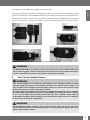
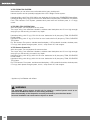
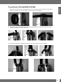
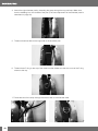
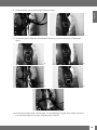
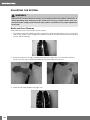
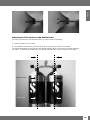
®
X-Tek
English
TABLE OF CONTENTS
IMPORTANT WARNINGS......................................................................................................... 2
CE CERTIFICATION.................................................................................................................. 2
EN 250: 2000 norm regulations and what they mean . ...............................................3
Definition of ‘SCUBA’ according to EN 250: 2000.......................................................3
Limitations provided by EN 250: 2000........................................................................3
IMPORTANT CAUTIONS.......................................................................................................... 3
GENERAL INFORMATION........................................................................................................ 4
Primary purpose of the Buoyancy Compensator.........................................................4
Initial set up.................................................................................................................4
WEIGHT SYSTEM:.................................................................................................................... 4
1.
2.
3.
Traditional Weight Belt......................................................................................4
Accessory Weight Pocket System....................................................................4
Tank Counter Weight Pouches..........................................................................5
VALVE SET UP........................................................................................................................... 6
Connecting the Power Inflator.....................................................................................6
OPERATION.............................................................................................................................. 6
Inflating the BC with the Power Inflation Valve.............................................................6
Inflating the BC with the Oral Valve..............................................................................6
Deflating the BC..........................................................................................................6
Deflating the BC with the Manual Dump Valve.............................................................7
Deflating the BC with the Oral Valve (BPI)....................................................................7
Over Pressure Valve Operation....................................................................................7
Shoulder Valves..........................................................................................................7
Lower Dump Valve . ...................................................................................................7
BC EXAMINATION AND PROCEDURES................................................................................. 8
Pre-Dive Visual Inspection and Valve Test....................................................................8
Low pressure Hose / Pneumatic Inflation Valve...........................................................9
X-TEK Systems...........................................................................................................9
Thread Guide: PRO HARNESS SYSTEM ............................................................................. 11
Thread Guide: PURE TEK HARNESS SYSTEM.................................................................... 21
Adjustment: FORM HARNESS SYSTEM............................................................................... 27
Thread Guide: SOFT TRAVEL BACK PACK.......................................................................... 30
Thread guide: SINGLE TANK ADAPTER............................................................................... 31
Attachment: SOFT BACKPLATE ON X-TEK FORM HARNESS........................................... 33
ADJUSTING THE SYSTEM:.................................................................................................... 34
Waist and Front Closures..........................................................................................34
AFTER THE DIVE ................................................................................................................... 35
Inspection and Service Interval..................................................................................35
TRANSPORT OF THE X-TEK SYSTEMS:.............................................................................. 36
Storage.....................................................................................................................36
GENERAL SPECIFICATIONS................................................................................................. 37
X-TEK WING BLADDERS....................................................................................................... 37
Bladder.....................................................................................................................37
Appendix................................................................................................................................. 38
Attachment: CLAMPS FOR TWIN TANKS.................................................................38
Adjustment of the bands on the double tanks...........................................................39
1
This information is for your safety. Please read the entire instruction manual before using your
X-TEK buoyancy compensator and equipment for the first time!
IMPORTANT WARNINGS
! WARNING
This manual must be read and understood entirely before using the product. It is advised
that you keep this manual in your possession during the entire life of your BC.
FAILURE TO READ, UNDERSTAND, AND FOLLOW THE PRECAUTIONS LISTED IN THIS
MANUAL COULD RESULT IN SERIOUS INJURY OR DEATH.
! WARNING
When diving you must follow the rules and apply the skills taught by a recognized scuba
diving certification agency. Before taking part in any diving activity, it is mandatory to have
successfully completed a scuba diving course covering both theoretical and technical
aspects of diving.
! WARNING
This instruction manual does not replace a diving instruction course!
CE CERTIFICATION
All SCUBAPRO BCs described in this manual have obtained the CE certification issued by a notified
body according to European directive 89/686/EEC. Certification tests have been conducted
according to the specifications set by the said directive, regulating the conditions for the release
on the market and the fundamental safety requirement for Personal Protective Equipment (PPE).
The CE mark denotes compliance with the fundamental requirements for health and safety. The
number next to the CE marking is the identification code for the notified body yearly controlling
production compliance with regulations, as per Art. 11A ED 89/686/EEC.
The BCs described in this manual has obtained the CE certification according the following
European norms:
- EN250:2000 for body harness that provides divers with a device for fixing the tank to the body:
it has not to be used deeper than 50 m (164 feet).
- EN1809:1997 European norm for jacket that provides divers with a buoyancy control device but
does not guarantee a head up position of the wearer at the surface.
Each BC model has an indication of the relevant EU certification obtained attached directly on
the BC.
! WARNING
THIS BC IS NOT A LIFEJACKET.
Emergency face up floatation may not be provided for all wearers and in all conditions.
! WARNING
This BC is not a breathing device. Never breathe from the BC. Your BC may contain gas
residue, liquid, or contamination that may result in injury or death if inhaled.
2
English
! WARNING
In accordance with European standards, our BCs can only be considered certified where
all components are present, as per the original SCUBAPRO configuration, including the
low pressure hose supplied.
Any variation of the original configuration invalidates conformity to European certification
standards.
EN 250: 2000 norm regulations and what they mean
The requirements and tests defined by the EN 250: 2000 standard aim to ensure a minimum
safety level for the operation of underwater breathing equipment. In Europe, the EN 250: 2000
norm defines the minimum technical standards of acceptance for recreational diving regulators. All
SCUBAPRO regulators have successfully passed the certification test required by this regulation.
Definition of ‘SCUBA’ according to EN 250: 2000
This regulation defines a SCUBA unit as a self-contained open-circuit underwater breathing
apparatus. A SCUBA unit can be composed of component groups. During use, the minimum
required component groups are elements a) to e) of the following list:
a. cylinder(s) with valve(s);
b. demand regulator(s);
c. safety device(s);
d. face mask: complete mouthpiece or half-mask for diving or complete mask;
e. carrying system.
Limitations provided by EN 250: 2000
The SCUBA unit can be comprised of separate components such as: cylinder(s), regulator(s)
and pressure gauge. The SCUBAPRO BCs described in this manual can be used with SCUBA
components units certified according to directive 89/686/EEC and EN 250: 2000 norm. The air
contained in the cylinder must comply with the requirements for breathable air defined by EN
12021 norm. The maximum operating depth is 50 meters (164 ft.) however divers must conform
to the limits set by local regulations in force at the diving location.
IMPORTANT CAUTIONS
For your protection while using SCUBAPRO life support equipment, we call your attention to the
following:
1. Use the equipment according to the instructions contained within this manual and only after
having completely read and understood all instructions and warnings.
2. Use of the equipment is limited to the uses described in this manual or for applications
approved in writing by SCUBAPRO.
3. Cylinders must only be filled with atmospheric compressed air, according to the EN 12021
norm. Should moisture be present in the cylinder, besides causing corrosion of the cylinder,
it may cause freezing and subsequent malfunction of the regulator during dives carried
out in low temperature conditions (lower than 10°C (50°F)). Cylinders must be transported
according to local rules provided for the transport of dangerous goods. Cylinder use is
subjected to the laws regulating the use of gases and compressed air.
4. Equipment must be serviced by qualified personnel at the prescribed intervals. Repairs and
maintenance must be carried out by an Authorized SCUBAPRO Dealer service facility and
with the exclusive use of original SCUBAPRO spare parts.
5. Should the equipment be serviced or repaired without complying with procedures approved
by SCUBAPRO or by untrained personnel or not certified by SCUBAPRO, or should it be
used in ways and for purposes other than specifically designated, liability for the correct and
safe function of the equipment transfers to the owner/user.
3
6. The content of this manual is based upon the latest information available at the time of going
to print. SCUBAPRO reserves the right to make changes at any time.
7. All dives must be planned and carried out so that at the end of the dive the diver will still have
a reasonable reserve of air for emergency use. The suggested amount is usually 50 bars
(725 psi).
SCUBAPRO refuses all responsibility for damages caused by non-compliance with the instructions
contained in this manual. These instructions do not extend the warranty or the responsibilities
stated by SCUBAPRO terms of sales and delivery.
! WARNING
Always perform a pre-dive and post-dive inspection of the BC.
GENERAL INFORMATION
Primary purpose of the Buoyancy Compensator
The primary purpose of a Buoyancy Compensator is to make you more comfortable by enabling
you to maintain neutral buoyancy at depth.
You are neutrally buoyant when you maintain a specific depth without expending significant
physical effort to prevent an ascent or descent from that depth.
! WARNING
Do not use your BC as an assist or “lift bag” for bringing objects to the surface. These
objects may be lost during the ascent, creating a sudden increase in buoyancy and loss
of buoyancy control.
Initial set up
Low Pressure (LP) hose
Connect the low pressure (LP) hose of the Power Inflation Valve to an unused LP port of the first
stage, which must have the same thread.
! WARNING
Do not attach a L.P. hose to a Scuba regulator high pressure (HP) port or to an air supply
with pressure in excess of 200 psi (13.8 bar). This may result in damage or explosive
failure of the Inflation Valve or Low pressure Hose, which could result in injury or death.
WEIGHT SYSTEM:
The total weight carried by the diver must be calculated and tested to allow neutral buoyancy
during the dive by simply adding or releasing the correct amount of air.
The SCUBAPRO B.C. can be used with several different ballast systems depending upon the
needs of the diver.
1.
Traditional Weight Belt
The weight belt should always be worn so it can drop freely from the diver. Failure to do so may
result an inability to ditch the weights and could result in serious injury or death.
2.
Accessory Weight Pocket System
The removable Buckle Weight Pocket System (BW) (Picture 1) is designed to be used with the
waist webbing of the X-Tek backplate system. Pictured below is the proper way to load and
secure the weight pockets into their pouches.
4
The weights are inserted into the weight pocket (Picture2)
English
The weight pockets are pushed into the weight pockets system (Picture 3+4) and held in proper
position by securing the quick release buckle and then pulling the strap until it is snug (Picture 5)
To release the weights from the pouch squeeze the tabs on the quick release buckle and pull the
pocket from the pouch. Release the weights once they are free from the pouch and your body.
3
1
2
To attach the optional weight pockets system please refer to page 26.
4
5
! WARNING
The Removable Pocket and pouch must be secured with the quick release buckle fully
and correctly engaged. The loss of the pocket during diving may cause positive buoyancy
and an uncontrolled ascent that could result in serious injury or death.
3.
Tank Counter Weight Pouches
! WARNING
Tank counter weights are not designed to be released in an emergency. Failure to create
adequate positive buoyancy in an emergency situation may result in injury or death. The
user of the BC must configure the entire diving system in a manner that provides rapid
positive buoyancy as an aid for emergency ascent.
The total weight carried by the diver must be calculated and tested in order to maintain
neutral buoyancy throughout the dive by simply adding or releasing the correct amount
of air. For this reason each bladder (model and size) has a different lifting capacity
(calculated using fresh water) marked on the model itself to assist the user in making a
correct choice for the gear configuration.
! WARNING
Using additional weights carried in bags or attached with clips may not be able to be
removed fast enough in an emergency situation to achieve positive buoyancy and could
lead to serious injury or death.
5
VALVE SET UP
SCUBAPRO X-TEK BC´s are completed by the BPI System(Balance Power Inflator). It is possible
to change the SCUBAPRO Balance Power Inflator to the X-TEK Inflator. This must be done by an
authorized dealer or the company SCUBAPRO. The power inflator, when connected to the tank
and regulator by a low pressure hose, makes it possible to control buoyancy in the water (inflation/
deflation of the BC) by using inflate and deflate buttons.
Connecting the Power Inflator
The Power Inflation Valve allows you to inflate your BC using air from your SCUBA cylinder. Its LP
hose, threaded on a LP port of the first stage regulator, is connected to the Power Inflation Valve
by the Quick Disconnect Coupling.
To attach the Quick Disconnect Coupling:
1.
Make sure that both fittings are free of contamination prior to connecting them together.
2.
Pull back the collar of the Quick Disconnect Coupling while pushing the hose firmly onto
the fitting plug found on the power inflation valve.
3.
Release the collar when the coupling is fully seated on the plug. Pull gently but firmly on the
hose to check for a secure connection.
4.
To disconnect, pull the Quick Disconnect Coupling collar back and disengage the LP hose
from the plug.
! WARNING
Keep water out of the inflatable aircell of the BC. Repeated use of the oral valve or the
Overpressure Valve may allow water inside the BC, reducing the amount of buoyancy
provided by the BC. This could result in injury or death. Drain all water out of the BC prior
to every use.
OPERATION
Inflating the BC with the Power Inflation Valve
To inflate the BC, press the Power Inflation Valve Button. Air should enter the BC. For better
control during inflation use short bursts of air by repeatedly pressing and releasing the power
inflator button.
Inflating the BC with the Oral Valve
The Oral Valve is found on the end of the airway. It allows you to inflate your BC with your exhaled
breath. Use of this valve for inflation is recommended on the surface or on land prior to diving. It
may be used when you cannot, or do not wish to add air to the BC with the Power Inflation Valve.
1.
First exhale a small amount of air into the mouthpiece of the valve to purge any water that
may be trapped there.
2.
With the same breath, continue to exhale while deeply depressing the Oral Inflation Valve
Button.
3.
Release the Oral Valve Button when you inhale fresh air.
4.
Repeat steps 2 and 3 until the desired amount of buoyancy is reached.
Deflating the BC
Your X-TEK system may be fitted with either a Manual Dump Valve or an Elbow without a
manual dump valve. Please follow the instructions for your particular BC configuration.
6
Deflating the BC with the Manual Dump Valve
English
(For Units fitted with the SCUBAPRO Manual Dump Valve)
Stop and assume an upright position in the water. When in position, open the Manual Dump Valve
by gently pulling downward on the Oral Valve/Power Inflation Valve Assembly. It is not necessary
to use excessive pressure to pull on the hose assembly. Valve travel is limited and pulling harder
will not increase the air flow. To close the Manual Dump Valve, stop pulling downward, and release.
! WARNING
Keep sand and other contamination out of the Oral Valve mouthpiece and valve button.
Under certain conditions, contamination can cause the valve to not close completely.
If this occurs while diving, shake the valve while depressing it several times. If the
valve leaks or remains inoperable, terminate the dive. Diving with a leaking Buoyancy
Compensator or with valves that do not operate properly may result in a loss of buoyancy
control that could result in injury or death.
Deflating the BC with the Oral Valve (BPI)
Assume a head up position in the water. Raise the Oral Valve above and in front of your face. (This
insures the Oral valve will be positioned above the air bubble in the BC). Depress the Oral Valve
button and visually confirm that air is escaping from the Inflator. For best control, let air out in a
series of short, measured amounts while observing the effects on your buoyancy.
! WARNING
• With all deflation methods, only keep the valve open as long as needed. This helps
prevent excess water from entering the BC.
• Do not depress the Oral Valve button when activating the Manual Dump Valve as water
may enter the BC through the Oral Valve mouthpiece.
Over Pressure Valve Operation
The Over Pressure Valve prevents over-inflation of the BC. If the internal pressure exceeds the
spring pressure in the Over Pressure Valve, the valve automatically opens and releases air to
prevent damage to the BC. The valve will automatically close when the internal pressure goes
below the spring pressure in the Over Pressure Valve (OPV).
Shoulder Valves
SCUBAPRO X-Tek bladders may have either an elbow or an overpressure valve on the left shoulder
that can also act as dump valves. The dump valve on the left shoulder is activated either by:
a) Pulling gently on the hose assembly.
b) If an OPV dump valve is not present on the left upper bladder then the diver should deflate
the BC using the manual dump function on the inflator.
Lower Dump Valve
Pressure Valves located at the lower rear of the bladder are equipped with lanyard and pull knob.
This lower Dump Valve can be manually activated when the Diver is in a horizontal or head down
orientation in the water, positioning them at the highest point of the air bubble.
7
! WARNING
Never breathe from the BC. Your BC may contain gas residue, liquid, or contamination
that may result in injury or death if inhaled.
Keep water out of the bladder of the BC. Repeated use of the oral valve or the Overpressure
Valve may allow water inside the BC, reducing the amount of buoyancy provided by the
BC. This could result in injury or death. Drain all water out of the BC prior to every use.
IMPORTANT!
•
•
With all deflation methods, keep the valve open no longer than needed. This helps
prevent excess water from entering the BC.
Do not depress the Oral Valve button when activating the Manual Dump valve, as
water may enter the BC through the Oral Valve mouthpiece.
BC EXAMINATION AND PROCEDURES
Pre-dive, dive and post-dive BC examination helps to identify equipment problems before unsafe
conditions exist, helping to prevent diving accidents. All equipment must be regularly inspected by
an authorized SCUBAPRO equipment repair facility to maintain its safe operation.
! WARNING
DO NOT DIVE with a BC that does not pass any of the Pre-Dive, Dive or Post-Dive
inspection points and tests. Diving with a BC that fails any of the listed check points could
result in the loss of buoyancy control while diving, resulting in serious injury or death.
Pre-Dive Visual Inspection and Valve Test:
1. Examine the entire BC for cuts, punctures, frayed seams, excessive abrasion, loose/missing
hardware and other damage of any kind.
2. Inspect the Oral Valve, Power Inflation Valve, Manual Dump Valve and Over Pressure Valve(s)
for cracks, damage, or contamination.
3. Operate the Power Inflation Valve (with the LP hose attached and charged with air pressure),
Oral Valve, manual Dump Valve and Over Pressure Valve, checking for proper operation and
resealing. If the OP Valve has a Pull Dump, test it by pulling on the cord.
4. Inflate the BC through the Oral Valve until it is firm. Listen and check for leaks. Let the BC
stand inflated for 30 minutes or more, and then check the BC for loss of air.
5. If applicable soak the cylinder band(s) and fit the BC to a SCUBA cylinder. Pull up on the BC
while it is attached on the SCUBA cylinder checking that the BC is secure and will not slip
while diving.
6. While wearing the BC, adjust the straps and other attachments on the BC for a comfortable
fit that does not restrict breathing. Make these adjustments with the BC inflated and while
wearing the exposure suit you intend to dive with.
7. Check quick release weight pockets or systems that retain weight (if your BC is equipped
with them). Make sure that their retention systems are fully and securely engaged. Confirm
that they can be quickly released and the weight freely removed from the system.
8. Do a buddy check with your dive partner confirming that all valves operate correctly prior to
entering the water.
8
English
! WARNING
DO NOT DIVE with a BC that is damaged, leaks air, or does not function properly.
Terminate any dive as safely and quickly as possible if the BC becomes damaged, leaks
air, or does not function properly.
Avoid prolonged or repeated exposure to chlorinated water, such as in swimming pools. Wash
your BC immediately after any use in chlorinated water. Chlorinated water can oxidize fabrics
and materials on your BC, thereby shortening their life, and cause colors (especially neon) to
fade. Damage and fading from prolonged exposure to chlorinated water is specifically not covered
under warranty.
! WARNING
Special Instruction in cold water diving methods, and the specific use of this product in
cold water, is required prior to cold water diving (temperatures below 10°C/50° F). This
instruction is beyond the scope of this manual.
Low pressure Hose / Pneumatic Inflation Valve
LP hose and Pneumatic Inflation Valve operating pressure
95 – 200 psi (6.5 – 13.8 bar)
Low Pressure Hose Fitting threads
3/8 – 24 UNF
O-Rings - Seals
EPDM – Buna/Nitrile - Silicone
! WARNING
This product is designed to use air or nitrogen/oxygen mixtures containing up to 40%
oxygen. Use of gas mixtures with increased oxygen, or the addition of helium or other
substances, may cause corrosion, deterioration, premature aging or component failure
of metal and rubber parts. These actions may result in loss of buoyancy control or air
holding integrity of the BC, resulting in injury or death. Non-standard gas mixtures may
also present a risk of fire or explosion. Use only nitrogen/oxygen mixtures containing up
to 40% oxygen.
X-TEK Systems
X-TEK PURE TEK SYSTEM
Specifically to the needs of the Pure TEK tailored jacket.
Donut Wing with 18 kg* (180 Lift N for max. bottle size 2x12l) buoyancy, SCUBAPRO Power Inflator.
Donut Wing with 18 kg* (180 Lift N for max. bottle size 2x12l) buoyancy, SCUBAPRO TEK Inflator.
Donut Wing with 13 kg* (135 Lift N for max. bottle size 15l) buoyancy, SCUBAPRO Power Inflator.
Pure TEK Harness: Pure TEK System, stainless steel backplate, 50 mm high-strength strap, 3
D-Rings, belt strap, crotch, belt stopper, single tank adapter.
X-TEK PURE TEK SYSTEM, Doubletank
Specifically to the needs of the Pure TEK tailored jacket.
Donut Wing with 27 kg* (270 Lift N for max. bottle size 2x12l) buoyancy , SCUBAPRO Power Inflator.
Donut Wing with 27 kg* (270 Lift N for max. bottle size 2x12l) buoyancy, SCUBAPRO TEK Inflator.
Pure TEK Harness: Pure TEK System, stainless steel backplate, 50 mm high-strength strap, 3
D-Rings, belt strap, crotch, belt stopper, single tank adapter.
9
X-TEK FORM TEK SYSTEM
Never before you can dive more comfortable with a heavy double tank.
Harness system can be optionally equipped with a QR- Weight Pocket system.
Horseshoe Wing, with 27 kg* (270 Lift N for max. bottle size 2x12l) buoyancy, SCUBAPRO Power Inflator.
Horseshoe Wing, with 27 kg* (270 Lift N for max. bottle size 2x12l) buoyancy, SCUBAPRO TEK Inflator.
Form TEK Harness: Form System, padded back panel with two shoulder pads, 6 x D-rings,
crotch.
X-TEK PRO TEK SYSTEM TWIN
With this system you are prepared for any dives.
Two Layer Wing, two redundant bladders, stainless steel backplate and 50 mm high-strength
strap give you the security you need in any depth.
Horseshoe Wing, with 27 kg* (270 Lift N for max. bottle size 2x12l) buoyancy, TWIN, SCUBAPRO
Power Inflator.
Horseshoe Wing, with 27 kg* (270 Lift N for max. bottle size 2x12l) buoyancy, TWIN, SUBAPRO
TEK Inflator.
Pro Tek Harness: Pro system, stainless steel backplate, 1 QR buckle left shoulder, shoulder pads,
5 D-rings, back plates storage system, crotch, strap 50mm HD, belt stopper.
X-TEK Xtreme System Pro
With this system you are prepared for extreme dives.
Two Layer Wing, two redundant bladders, stainless steel backplate and 50 mm high-strength
strap give you the security you need in any depth.
Horseshoe Wing, with 40 kg* (400 Lift N for max. bottle size 2x12l) buoyancy, TWIN, SCUBAPRO
Power Inflator.
Horseshoe Wing, with 40 kg* (400 Lift N for max. bottle size 2x12l) buoyancy, TWIN, SCUBAPRO
TEK Inflator.
Pro TEK Harness: Pro system, stainless steel backplate, 1 QR buckle left shoulder, shoulder pads,
5 D-rings, back plates storage system, crotch, strap 50mm HD, belt stopper.
* Applies only for Bladder with Inflator
! WARNING
The assembly of the system should only be done by a trained person such as an
authorized SCUBAPRO Dealer to avoid wrong assembly.
After the assembly, a final inspection must be performed by an authorized dealer.
Incorrect installation can cause serious injuries or death.
10
Thread Guide: PRO HARNESS SYSTEM
a.
English
1. Place the webbing with the hole aligned onto the center rear of the backplate. Depending of
height of your tank you use the upper or lower hole at the backplate.
b.
2. Thread the right end of the strap through the right angled slot at the top of the back plate.
Repeat the procedure with the left side.
a.
b.
.
c.
3. Thread the ends of the webbing through the top horizontal slits on the backplate.
a.
b.
c.
front view
rear view
11
4. Attach the right shoulder pad by threading the strap through the top pad loop. Make sure
that the webbing is on the outside of the pad. (The exact adjustment of the shoulder pads is
described on page 34).
5. Thread a three bar slide on the right side to the shoulder pad.
6. Thread a bent D-ring to the top of the three bar slide. Make sure that the curve of the D-ring
shows to the top.
7. Thread the end of the strap through the second slot of the three bar slide.
a.
12
b.
English
8. Thread the end of the strap through the second loop.
a.
b.
9. Thread the second three bar slide between the second and the third loop, as described
above.
a.
b.
c.
d.
e.
10.Thread the three bar slide- without teeth- on the webbing for the left strap. Make sure that it
is at the same height as the right shoulder strap is located.
13
11.Thread the webbing through all loops of the left shoulder pad. Make sure that the webbing is
on the outside of the shoulder pad.
12.Thread the end of the strap through the lower slot of the female Quick Release Buckle.
13.Thread the webbing through the first loop of the shoulder pad.
14.Thread the three bar slide and the D-rings as described in section 5-8 above.
14
English
a.
b.
c.
d.
e.
f.
g.
h.
15
i.
j.
k.
l.
15.Thread the end of the webbing through the top of the three bar slide (see 10).
a.
b.
c.
16.Snap the quick release buckle together.
a.
16
b.
English
17.Thread the end of the webbing for the bottom left strap from the inside out through the inner
slot.
18.Thread a three bar slide to the webbing and thread the end of it from the outside in, through
the outer slot.
a.
b.
c.
d.
e.
rear view
f.
front view
17
19.Thread a three bar slide about 4 inches (10cm) away from the front of the backplate.
20.Thread a flat D-ring up to the three bar slide and then lead the end of the webbing through
the second slot of the three bar slide.
a.
b.
21.Attach the buckle as shown:
a.
b.
c.
d.
e.
f.
g.
18
English
22.Thread the right end of the webbing in the same manner as described in step 18 on Page 16.
a.
b.
d.
c.
e.
19
23.Attaching the crotch strap:
Place the inverted plate on a table, so that you can see the backside of the plate. Place the
crotch strap in front of you, so that the D-ring with the three bar slide is facing up. Thread the
upper end of the strap from back to front through the lower slot of the backplate.
24.Thread the end of the strap through the three bar slide and the D-ring.
a.
c.
20
b.
d.
e.
English
25.Thread the other end of the crotch strap with the loop on the waistband.
! WARNING
When using a weight belt with the crotch strap you must place the weight belt on top
of the crotch strap so it can fall freely from your body. Failure to follow this practice will
prevent the weight belt from being released and may result in serious injury or death.
Thread Guide: PURE TEK HARNESS SYSTEM
1. Place the webbing with the hole down onto the rear of the backplate. Depending of height of
your tank you use the upper or lower hole at the backplate.
a.
b.
2. Thread the right end of the webbing through the right angled slot at the top of the back plate.
Repeat the procedure with the left side.
a.
b.
rear view
c.
front view
21
3 Thread the ends of the webbing through the top horizontal slits of the front through the
backplate.
a.
front view
rear view
b.
rear view
c.
rear view
d.
e.
f.
front view
4. Thread a three bar slide and a curved D-ring to the webbing on the right side. Make sure
that the curve is facing up.
a.
b.
c.
d.
5. Thread a three bar slide and a D-ring on the other side as described above.
a.
22
b.
c.
English
6. Thread the left end of the webbing from the inside out through the inner slot.
7. Thread a three bar slide to the webbing and thread the end of the strap from the outside in,
through the outer slot.
a.
b.
c.
d.
e.
23
8. Thread a three bar slide to about 4 inches (10cm) from the front of the backplate.
9. Thread a flat D-ring up to the three bar slide and then lead the end of the webbing through
the second slot of it.
a.
b.
c.
10.Attach the buckle as shown:
a.
24
b.
English
c.
d.
e.
f.
g.
25
11.Thread the right side of the webbing as described in steps 6, 7 & 8 on Pages 22 & 23.
26
a.
b.
c.
d.
e.
f.
g.
h.
i.
English
Adjustment: FORM HARNESS SYSTEM
You have the option to position the shoulder straps at the Form Harness System in different ways:
1. Thread the strap with the stainless steel buckle inward, in order to position the shoulder
straps further back.
Weight Pocket
a.
b.
c.
d.
e.
f.
27
g.
h.
i.
2. Thread the strap with the stainless steel buckle outward, in order to position the shoulder
straps on the outside.
28
a.
b.
c.
d.
English
e.
f.
g.
h.
3. To widen the placement of the straps you can adjust them to the desired position. Use the
same instructions as described above.
29
Thread Guide: SOFT TRAVEL BACK PACK
Super Cinch Tank Strap:
1. Set the soft backplate in front of you, so you see the loops.
Unthread the D-ring and the plastic stopper.
a.
b.
2. Thread the Super Cinch belt without the grommets through the upper loop.
3. Thread the Super Cinch strap with grommets through the bottom two loops and making sure
the holes match those on the soft backpad.
30
English
4. Thread the plastic stopper first and then add the D-ring.
a.
b.
view up
c.
view side
Thread guide: SINGLE TANK ADAPTER
Remove the D-ring and the plastic stopper from the Super cinch strap and then thread it though
the slots of the adapter. Replace the plastic stopper first and the the D-ring.
a.
b.
c.
Attachment of the single tank adapter to the X-TEK Form Harness, Pro Harness, Pure Tek Harness
in conjunction with the stainless steel backplate:
31
1. Place the backplate so it is facing down and then place the bladder onto the backplate.
a.
b.
2. Place the single tank adapter on the bladder so that the grommets are on top of each other.
Insert the screw from the bottom of the backplate and through the grommets and tighten the
nut from the top.
a.
b.
3. Repeat on the bottom of the adaptor. The single tank adaptor must be attached with two
screws to be secure. Failure to use two screws may lead to the bladder not being securely
attached to the plate which might lead to the tank being lost and could lead to serious injury
or death.
32
Attachment: SOFT BACKPLATE ON X-TEK FORM HARNESS
English
! WARNING
Check the tightness of the screws and nuts before each dive. The system must be
securely fastened together to be used safely. Failure to check the security of the system
may lead to the tank becoming detached before, during, or after the dive and could lead
to serious injury or death
1. Place the soft backplate onto the bladder with the loops facing down and the Super cinch
buckles on the left.
2. Place the bladder onto the back of the Form Harness. Make sure that the grommets on the
soft backplate, bladder, and Form Harness line up with each other.
3. Insert the screws from the bottom through the grommets and tighten the nuts securely.
Tip: Start at the top of the outer eyelet to the left and then the outer eyelet on the top right.
Following the numbers shown below (1-6).
4
1
3
5
2
6
33
ADJUSTING THE SYSTEM:
! WARNING
Adjust the BC so that it does not restrict your breathing when fully inflated. Restriction of
normal breathing while wearing your BC could result in injury or death. Before each use,
check all bands, straps, quick-connect clips, and/or cummerbund for proper adjustment
to the user.
Waist and Front Closures
Waist closures mostly use a buckle closure system.
1. To properly adjust the webbing system, thread first a three bar slide and a D-ring, on the right
side of your system. (Don’t forget the to take into account the extra thickness of the exposure
suit you will be wearing).
2. Place the strap over the right shoulder and stretch the right arm out to the side. Point the
thumb on the D-ring. It should be parallel at the same height as your arm.
3. Adjust the left side parallel to the right one.
34
English
4. To perform the next setting, thread the end of the straps as described in Point 7 at Page 22.
5. Pull on the system and grasp with the arm over your shoulder. You should be able to grasp
with the fingertips to the top of the back plate.
AFTER THE DIVE
Cleaning the BC, Check, Storage and Transport:
Correct servicing and maintenance guarantees you many years reliable function of your
SCUBAPRO® X-TEK BC.
Keep the following instructions for care:
•
Fill the bladder with fresh water and shake so that the water reaches everywhere.
•
Keep the bladder upside down and press the exhaust button on the inflator so that all the
water can drain.
•
Disinfect the inner bladder on a regular basis to prevent bacterial growth.
•
Rinse the outer shell thoroughly with fresh water.
•
Clean all valves so that possible dirt is removed.
•
Place a small amount of silicone on the quick release collar for the power inflator
attachement (SCUBAPRO® silicone grease).
•
Slightly inflate the bladder and hang it up for drying. Do not dry or store the bladder in
direct sunlight.
•
Dry store the BC slightly inflated in a cool dry place, protected from direct sunlight.
Inspection and Service Interval:
For your safety your BC should be inspected and maintained at an Authorized SCUBAPRO
Service Center at least once a year, more often if you dive frequently. Any damage caused due to
failure to properly maintain the BC is not covered by the warranty.
35
TRANSPORT OF THE X-TEK SYSTEMS:
Handle the XTEK systems in such a way to ensure that no sharp or heavy objects (e.g. knives,
bottles, lamps, lead etc.) damage the harness, bladder, or inflators.
IMPORTANT!
Avoid prolonged or repeated exposure to chlorinated water, such as in swimming pools.
Wash your BC immediately after any use in chlorinated water. Chlorinated water can
oxidize fabrics and materials on your BC, thereby shortening its life, and cause colors
(especially neon) to fade. Damage and fading from prolonged exposure to chlorinated
water is specifically not covered under warranty.
Storage
Store your BC, after it has fully dried, by partially inflating and then placing it in a cool, dark, dry,
location: ultraviolet rays will shorten the life of the fabric and cause colors to fade. Slightly grease
(with SCUBAPRO Lubricant Grease) Power Inflator couplings.
36
GENERAL SPECIFICATIONS
English
Shelf life:
Shelf life is seven years for a new, unused BC when deflated and stored in a sealed container or
bag at typical room temperature, with no exposure to UV.
Operating temperature range:
Air
-20°C
to
+50°C
-4°F
to
122°F
Water
-2°C
to
+40°C
28°F
to
104°F
X-TEK WING BLADDERS
Diving with a back inflation wing BC is different from a standard BC. The X-Tek system uses either
a Horseshoe or Donut shaped bladder.
Bladder:
Each bladder is constructed of a 1680DEN Ballistic Nylon outer cover and one or more inner
bladders constucted from 420 D Nylon.
Be aware of the position of the valves when you deflate the bladder. If you want to deflate the
bladder in a head down position you have to make sure that exhaust valves are at the highest
position in relationship to the air bubble inside the bladder.
Please note, that there may be air in both sides of the Horseshoe bladder.
For normal deflation of your BC you may have to assume a head up position.
! WARNING
Wing BCs are built for a stable position under water. The X-TEK jacket is not a life jacket.
The inflated jacket doesn’t guarantee an unconscious diver will be in a safe heads-up
position at the surface!
IMPORTANT!
The use of the X-Wing TEK BCs should be practiced in a controllable environment, e.g.
in a swimming pool before diving. The user must be familiar with the operation and skills
needed to safely use the system. Failure to be fully competent in the use of the jacket
may result in serious injury or death!
37
Appendix
Attachment: CLAMPS FOR TWIN TANKS
1. Put the clamps onto the double tank. (The setting of the clamps for the tank bottles, as
described on pages 39-40).
2. Turn the screws for the clamps from back to front, towards the backplate.
3. Fix a washer and locking nut from the side you have fasten the screw.
4. Attach an additional washer and locking nut at the other side where the screw is exited.
5. Tighten the nuts so hard, that the clamps do not slip anymore.
6. Slide the bladder with the eyelets on the outward screws.
7. Slide the backplate on the outward screws.
8. Attach a washer and a retaining ring to the screw and tighten with a wing screw.
Arrangement of the screws and washers:
1
2
3
4
Backplate and
Bladder
38
English
Adjustment of the bands on the double tanks:
For setting the bands on the double tanks, you should note the following:
• Attach the bands to the tanks.
• The distance between the two tank valves is set by using the connector manifold.
The distance between the tank bands (see sample drawing below), has to be the same as between
the valves. To determine the distance, you always measure from center to center of the object.
Middle Clamps
Middle Tank
39
Procedure:
1.
Set the tanks parallel, the valves showing in one direction.
2.
Screw the connector manifold into a valve. The space between A and B, (see picture
above) should be exactly the same as the measure between the clamps. (See sample
drawing page 37).
3.
Fit the clamps on the Double Tanks and fix it, as described on pages 38-39.
4.
Rotate the connector careful into the valves. Take a tape measure and gauge the distance
between the valves to obtain the exact distance.
Space to be measured
A
B
IMPORTANT!
Make sure that the space between the valves is exactly the same as those of the bands;
otherwise the valve manifold can be damaged.
40
English
The following accessories are available through an authorized SCUBAPRO dealer:
Item Number
Description
23802000
X-TEK Single Tank Adapter
23803000
X-TEK QR-Weight Pocket system
23807000
X-TEK Soft Travel Backplate
23808000
X-TEK Backplate Storage Pack
23809000 X-TEK Shoulder Pad
23810000
X-TEK Accessory Bag small
23811000
X-TEK Accessory Bag big
23812000 X-TEK Counter Weight Pockets
23817000 X-TEK Buoy Bag
23813000
X-TEK Inflator
23814000
X-TEK Double -Tank Clamps ss140mm
23815000 X-TEK Double -Tank Clamps ss171mm
23816000 X-TEK Double -Tank Clamps ss204mm
21200217
SCUBAPRO Quick Stop Valve
22193010 X-TEK Donut Wing 13kg
41
Test according to DIN EN 1809:1998-1 Buoyancy
Notified body 0299 BG Bau, Arbeitsschutzzentrum Haan, Zentrum fuer Sicherheitstechnik,
Zwengenberger Str. 68, 42781 Hann, Germany.
42
SUBSIDIARIES
SCUBAPRO
ASIA PACIFIC
1208 Block A, MP Industrial Center
18 Ka Yip St.
Chai Wan - Hong Kong
SCUBAPRO GERMANY
Johnson Outdoors
Vertriebsgesellschaft mbH
Johann-Höllfritsch-Str.47
90530 Wendelstein - Germany
SCUBAPRO
SWITZERLAND
Oberwilerstrasse 16
CH-8444 Henggart - Switzerland
SCUBAPRO
AUSTRALIA
Unit 21 380 Eastern Valley Way
Chatswood NSW 2067 - Australia
SCUBAPRO
ITALY
Via Tangoni, 16
16030 Casarza Ligure (GE) - Italy
SCUBAPRO
U.K.
Vickers Business Centre
Priestley Road,
Basingstoke, Hampshire RG24 9NP
England
SCUBAPRO
BENELUX
Leuvense Steenweg 775
775 Chaussée de Louvain
1140 Brussels - Belgium
SCUBAPRO
JAPAN
Mitsubishi Juko Yokohama Bldg. 22F
3-3-1 Minatomirai, Nishi-ku
Yokohama 220-0012 - Japan
SCUBAPRO AMERICAS
Johnson Outdoors Diving LLC
1166-A Fesler Street
El Cajon, CA 92020-USA
SCUBAPRO
FRANCE
Nova Antipolis Les Terriers Nord
175 Allée Belle Vue
06600 Antibes - France
SCUBAPRO
SPAIN
Pere IV, 359, 2º
08020 Barcelona - Spain
For additional information about our distributors and dealers, see our web site at: www.scubapro.com
© 2010 by Johnson Outdoors Inc.
®
P/N 45.021.005 • 10/2010 • 59681010