1
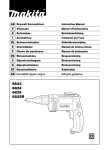
GB Drywall Screwdriver
Instruction Manual
F
Visseuse
Manuel d’instructions
D
Schrauber
Betriebsanleitung
I
Avvitatrice
Istruzioni per l’uso
NL Schroevedraaier
Gebruiksaanwijzing
E
Atornillador
Manual de instrucciones
P
Chave de parafusos
Manual de instruções
DK Skruemaskine
Brugsanvisning
S
Gipsskruvdragare
Bruksanvisning
N
Gipsskrutrekker
Bruksanvisning
SF Ruuvinväännin
Käyttöohje
GR Κατσαβίδι ξηρού τοίχου
Οδηγίες χρήσεως
6823N
6824N
A
2
3
B
1
1
2
2
3
3
1
3
4
3
7
4
6
5
5
6
A
B
8
7
2
8
A
B
9
9
10
Symbols
The followings show the symbols used for the tool. Be sure that you understand their meaning before use.
Symboles
Nous donnons ci-dessous les symboles utilisés pour l’outil. Assurez-vous que vous en avez bien compris la signification avant d’utiliser l’outil.
Symbole
Die folgenden Symbole werden für die Maschine verwendet. Machen Sie sich vor der Benutzung unbedingt mit ihrer
Bedeutung vertraut.
Simboli
Per questo utensile vengono usati i simboli seguenti. Bisogna capire il loro significato prima di usare l’utensile.
Symbolen
Voor dit gereedschap worden de volgende symbolen gebruikt. Zorg ervoor dat u de betekenis van deze symbolen
begrijpt alvorens het gereedschap te gebruiken.
Símbolos
A continuación se muestran los símbolos utilizados con esta herramienta. Asegúrese de que entiende su significado
antes de usarla.
Símbolos
O seguinte mostra os símbolos utilizados para a ferramenta. Certifique-se de que compreende o seu significado antes
da utilização.
Symboler
Nedenstående symboler er anvendt i forbindelse med denne maskine. Vær sikker på, at De har forstået symbolernes
betydning, før maskinen anvendes.
Symboler
Det följande visar de symboler som används för den här maskinen. Se noga till att du förstår deras innebörd innan
maskinen används.
Symbolene
Følgende viser de symblene som brukes for maskinen. Det er viktig å forstå betydningen av disse før maskinen tas i
bruk.
Symbolit
Alla on esitetty koneessa käytetyt symbolit. Opettele näiden merkitys, ennen kuin käytät konetta.
Σύµβολα
Τα ακλουθα δείχνουν τα σύµβολα που χρησιµοποιούνται για το µηχάνηµα. Βεβαιωθείτε τι καταλαβαίνετε
τη σηµασία τους πριν απ τη χρήση.
❏ Read instruction manual.
❏ Lire le mode d’emploi.
❏ Bitte Betriebsanleitung lesen.
❏ Leggete il manuale di istruzioni.
❏ Lees de gebruiksaanwijzing.
❏ Lea el manual de instrucciones.
❏ Leia o manual de instruções.
❏ Læs brugsanvisningen.
❏ Läs bruksanvisningen.
❏ Les bruksanvisingen.
❏ Katso käyttöohjeita.
❏ ∆ιαβάστε τις οδηγίες χρήσης.
❏ DOUBLE INSULATION
❏ DOUBLE ISOLATION
❏ DOPPELT SCHUTZISOLIERT
❏ DOPPIO ISOLAMENTO
❏ DUBBELE ISOLATIE
❏ DOBLE AISLAMIENTO
❏ DUPLO ISOLAMENTO
❏ DOBBELT ISOLERET
❏ DUBBEL ISOLERING
❏ DOBBEL ISOLERING
❏ KAKSINKERTAINEN ERISTYS
❏ ∆ΙΠΛΗ ΜΟΝΩΣΗ
3
ENGLISH
Explanation of general view
1
2
3
Locking sleeve
Approximately 1 mm
Locator
4
5
6
Bit
Magnetic bit holder
Switch trigger
7
8
9
Lock button
Reversing switch lever
Hook
SPECIFICATIONS
Model
6823N
Capacities
Self drilling screw ................................................................................... 6 mm
Drywall screw ......................................................................................... 6 mm
No load speed (min–1) ............................................................................... 0 – 2,500
Overall length ............................................................................................ 301 mm
Net weight ................................................................................................. 1.5 kg
• Due to our continuing program of research and development, the specifications herein are subject to change
without notice.
• Note: Specifications may differ from country to country.
Intended use
The tool is intended for screw driving in wood, metal and
plastic.
Power supply
The tool should be connected only to a power supply of
the same voltage as indicated on the nameplate, and can
only be operated on single-phase AC supply. They are
double-insulated in accordance with European Standard
and can, therefore, also be used from sockets without
earth wire.
Safety hints
For your own safety, please refer to the enclosed safety
instructions.
ADDITIONAL SAFETY RULES
ENB004-1
1.
2.
3.
4.
5.
Hold tool by insulated gripping surfaces when
performing an operation where the cutting tools
may contact hidden wiring or its own cord. Contact with a “live” wire will make exposed metal
parts of the tool “live” and shock the operator.
Always be sure you have a firm footing. Be sure
no one is below when using the tool in high locations.
Hold the tool firmly.
Keep hands away from rotating parts.
Do not touch the bit or the workpiece immediately after operation; they may be extremely hot
and could burn your skin.
SAVE THESE INSTRUCTIONS.
6824N
6 mm
5 mm
0 – 4,500
290 mm
1.4 kg
OPERATING INSTRUCTIONS
CAUTION:
Always be sure that the tool is switched off and
unplugged before adjusting or checking function on the
tool.
Depth adjustment
The depth can be adjusted by turning the locking sleeve.
Turn it in “A” direction for less depth and in “B” direction
for more depth. One full turn of the locking sleeve equals
1.5 mm change in depth. (Fig. 1) Adjust the locking
sleeve so that the distance between the tip of the locator
and the screw head is approximately 1 mm as shown in
Fig. 2 or 3. Drive a trial screw into your material or a
piece of duplicate material. If the depth is still not suitable
for the screw, continue adjusting until you obtain the
proper depth setting. (Fig. 2 & 3)
Installing or removing bit (Fig. 4 & 5)
Important:
Always be sure that the tool is switched off and
unplugged before removing or installing the bit.
To remove the bit, first pull the locator out of the locking
sleeve. Then grasp the bit with a pair of pliers and pull the
bit out of the magnetic bit holder. Sometimes, it helps to
wiggle the bit with the pliers as you pull.
To install the bit, push it firmly into the magnetic bit
holder. Then install the locator by pushing it firmly back
onto the locking sleeve.
Switch action (Fig. 6)
CAUTION:
Before plugging in the tool, always check to see that the
switch trigger actuates properly and returns to the “OFF”
position when released.
To start the tool, simply pull the switch trigger. Tool speed
is increased by increasing pressure on the switch trigger.
Release the switch trigger to stop. For continuous operation, pull the switch trigger and then push in the lock button. To stop the tool from the locked position, pull the
switch trigger fully, then release it.
NOTE:
Even with the switch on and motor running, the bit will not
rotate until you fit the point of the bit in the screw head
and apply forward pressure to engage the clutch.
4
Reversing switch action (Fig. 7)
MAINTENANCE
CAUTION:
• Always check the direction of rotation before opration.
• Use the reversing switch only after the tool comes to a
complete stop. Charging the direction of rotation before
the tool stops may damage the tool.
CAUTION:
Always be sure that the tool is switched off and
unplugged before carrying out any work on the tool.
This tool has a reversing switch to change the direction of
rotation. Move the reversing switch lever to the D position (A side) for clockwise rotation or the E position
(B side) for counterclockwise rotation.
Operation
Fit the screw on the point of the bit and place the point of
the screw on the surface of the workpiece to be fastened.
Apply presssure to the tool and start it. Withdraw the tool
as soon as the clutch cuts in. Then release the switch
trigger.
CAUTION:
• When fitting the screw onto the point of the bit, be careful not to push in on the screw. If the screw is pushed
in, the clutch will engage and the screw will rotate suddenly. This could damage a workpeice or cause an
injury.
• Make sure that the bit is inserted straight in the screw
head, or the screw and/or bit may be damaged.
• Do not continue unnecessary clutching operation.
To maintain product safety and reliability, repairs, maintenance or adjustment should be carried out by a Makita
Authorized Service Center.
ACCESSORIES
CAUTION:
• These accessories or attachments are recommended
for use with your Makita tool specified in this manual.
The use of any other accessories or attachments might
present a risk of injury to persons. Only use accessory
or attachment for its stated purpose.
If you need any assistance for more details regarding
these accessories, ask your local Makita service center.
• Phillips insert bit 1-25, 2-25 and 3-25
• Magnetic bit holder 6.35-76 and 6.35-60
Hook (Fig. 9 & 10)
The hook is convenient for temporarily hanging the tool.
When using the hook, pull it out in “A” direction and then
push it in B direction to secure in place.
When not using the hook, return it back to its initial position by following the above procedures in reverse.
How to remove
Rotate the Removable Cord Adapter counterclockwise
until it stops while pressing the lower part of the lock button. (Fig. 14)
Then pull the Removable Cord Adapter in that position.
(Fig. 15)
5
NEDERLANDS
Verklaring van algemene gegevens
1
2
3
Borghuls
Ongeveer 1 mm
Locator
4
5
6
Bit
Magnetische bithouder
Trekschakelaar
7
8
9
Vergrendelknop
Omkeerschakelaar
Haak
TECHNISCHE GEGEVENS
Model
6823N
Capaciteiten
Zelfborende schroef ............................................................................... 6 mm
Gipsplaatschroef .................................................................................... 6 mm
Toerental onbelast (min–1) ......................................................................... 0 – 2 500
Totale lengte .............................................................................................. 301 mm
Netto gewicht ............................................................................................. 1,5 kg
• In verband met ononderbroken research en ontwikkeling behouden wij ons het recht voor bovenstaande
technische gegevens te wijzigen zonder voorafgaande
kennisgeving.
• Opmerking: De technische gegevens kunnen van land
tot land verschillen.
Doeleinden van gebruik
Dit gereedschap is bedoeld voor het indraaien van
schroeven in hout, metaal en kunststof.
Stroomvoorziening
De machine mag alleen worden aangesloten op een
stroombron van hetzelfde voltage als aangegeven op de
naamplaat, en kan alleen op enkel-fase wisselstroom
worden gebruikt. De machine is dubbel-geïsoleerd volgens de Europese standaard en kan derhalve ook op
een niet-geaard stopkontakt worden aangesloten.
Veiligheidswenken
Voor uw veiligheid dient u de bijgevoegde Veiligheidsvoorschriften nauwkeurig op te volgen.
AANVULLENDE
VEILIGHEIDSVOORSCHRIFTEN
1.
2.
3.
4.
5.
Houd het gereedschap bij de geïsoleerde handgreepoppervlakken vast wanneer u boort op
plaatsen waar de boor met verborgen bedrading
of zijn eigen netsnoer in contact kan komen.
Door contact met een onder spanning staande
draad zullen de niet-geïsoleerde metalen delen
van het gereedschap onder spanning komen te
staan zodat de gebruiker een elektrische schok
kan krijgen.
Zorg altijd dat u stevig op uw voeten staat. Zorg
dat wanneer u op hooggelegen plaatsen werkt,
niemand onder u staat.
Houd het gereedschap stevig vast.
Houd uw handen uit de buurt van de draaiende
delen.
Raak onmiddellijk na het inschroeven de bit niet
aan, aangezien deze ontzettend heet kan zijn en
brandwonden kan veroorzaken.
BEWAAR DEZE VOORSCHRIFTEN.
12
6824N
6 mm
5 mm
0 – 4 500
290 mm
1,4 kg
BEDIENINGSVOORSCHRIFTEN
LET OP:
Zorg altijd dat het gereedschap is uitgeschakeld en de
stekker ervan uit het stopcontact is verwijderd vooraleer
u begint met afstelling of onderhoud van het gereedschap.
Instellen van de diepte
De diepte kan worden ingesteld door de borghuls te
draaien. Draai deze in de “A” richting voor minder diepte
en in de “B” richting voor meer diepte. Een volle slag van
de borghuls komt overeen met een 1,5 mm verandering
in diepte. (Fig. 1)
Stel de borghuls zo in dat de afstand tussen het uiteinde
van de locator en de schroefkop ongeveer 1 mm
bedraagt, zoals afgebeeld in Fig. 2 of 3. Maak een proef
door een schroef in uw materiaal of in een gelijksoortig
materiaal te draaien. Indien de diepte niet juist is voor de
betreffende schroef, dient u verder af te stellen totdat de
juiste diepte-instelling is verkregen. (Fig. 2 en 3)
Verwijderen of installeren van de bit (Fig. 4 en 5)
Belangrijk:
Zorg altijd ervoor dat het gereedschap is uitgeschakeld
en de stekker uit het stopcontact is verwijderd, alvorens
de bit te verwijderen of te installeren.
Om de bit te verwijderen, trekt u eerst de locator uit de
borghuls. Houd daarna de bit met een tang vast en trek
hem uit de magnetische bithouder. Het uittrekken is
soms gemakkelijker wanneer u de bit met de tang wat
heen en weer beweegt.
Om de bit te installeren, drukt u deze stevig in de magnetische bithouder. Installeer vervolgens de locator door
deze stevig op de borghuls te drukken.
Bediening van de trekschakelaar (Fig. 6)
LET OP:
Alvorens de stekker in een stopcontact te steken, dient u
altijd te controleren of de trekschakelaar naar behoren
werkt en bij loslaten onmiddellijk naar de “OFF” positie
terugkeert.
Om de machine te starten, de trekschakelaar gewoon
indrukken. Het toerental vermeerdert naarmate de schakelaar harder wordt ingedrukt. Laat de schakelaar los om
de machine te stoppen. Voor continu gebruik, de trekschakelaar indrukken en dan de vergrendelknop indrukken. Om de machine vanuit deze vastzetpositie te
stoppen, de trekschakelaar volledig indrukken en deze
dan loslaten.
OPMERKING:
Zelfs wanneer u de trekschakelaar indrukt en de motor
draait, zal de bit niet draaien voor u de punt van de bit op
de schroefkop plaatst en voorwaartse druk uitoefent om
de koppeling in te schakelen.
Bediening van de omkeerschakelaar (Fig. 7)
LET OP:
• Controleer altijd de draairichting alvorens de machine
te gebruiken.
• Gebruik de omkeerschakelaar alleen nadat de machine
volledig tot stilstand is gekomen. Indien u de draairichting verandert voordat de machine is gestopt, kan de
machine beschadiging oplopen.
ACCESSOIRES
LET OP:
• Deze accessoires of hulpstukken worden aanbevolen
voor gebruik met het Makita gereedschap dat in deze
gebruiksaanwijzing is beschreven. Bij gebruik van
andere accessoires of hulpstukken bestaat er gevaar
voor persoonlijke verwonding. Gebruik de accessoires
of hulpstukken uitsluitend voor hun bestemde doel.
Raadpleeg het dichtstbijzijnde Makita Servicecentrum
voor verder advies of bijzonderheden omtrent deze
accessoires.
• Phillips insteekbit 1-25, 2-25 en 3-25
• Magnetische bithouder 6,35-76 en 6,35-60
Dit gereedschap heeft een omkeerschakelaar voor het
veranderen van de draairichting. Druk de omkeerschakelaar naar de positie D (zijde A) voor rechtse draairichting, of naar de positie E (zijde B) voor linkse
draairichting.
Bediening
Plaats de schroef op de punt van de bit en plaats de punt
van de schroef op het te bevestigen werkstuk. Oefen
druk uit op de machine en start deze. Trek de machine
terug zodra de koppeling ingrijpt. Laat daarna de trekschakelaar los.
LET OP:
• Wanneer u de schroef op de punt van de bit aanbrengt,
moet u ervoor zorgen dat u de schroef niet naar binnen
drukt. Als de schroef naar binnen wordt gedrukt, kan
de koppeling worden ingeschakeld zodat de schroef
plotseling begint te draaien. Dit kan beschadiging van
het werkstuk of verwonding veroorzaken.
• Zorg ervoor dat de bit recht in de schroefkop zit, aangezien de schroef en/of bit anders beschadigd kunnen
raken.
• Houd de koppeling niet langer dan nodig ingedrukt.
Haak (Fig. 9 en 10)
De haak is handig om het gereedschap tijdelijk op te
hangen. Om de haak te gebruiken, trekt u deze naar buiten in de “A” richting en dan duwt u deze in de “B” richting om hem vast te zetten.
Wanneer u de haak niet gebruikt, volgt u de bovenstaande procedure in omgekeerde volgorde om de haak
naar zijn oorspronkelijke positie terug te brengen.
Verwijderen
Houd het onderste gedeelte van de vergrendelknop ingedrukt en draai de verwijderbare kabeladapter naar links
totdat hij stopt. (Fig. 14)
Trek daarna de verwijderbare kabeladapter eruit.
(Fig. 15)
ONDERHOUD
LET OP:
Zorg er altijd voor dat de machine is uitgeschakeld en de
stekker uit het stopcontact is verwijderd alvorens onderhoud aan de machine uit te voeren.
Opdat het gereedschap veilig en betrouwbaar blijft, dienen alle reparaties, onderhoud of afstellingen te worden
uitgevoerd bij een erkend Makita service centrum.
13