1
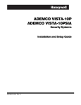
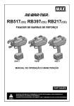
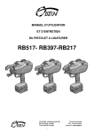
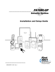
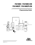
ADEMCO VISTA-20P Series / VISTA-15P Series Security Systems Quick Installation Guide (A copy of the Installation and Setup Guide is available upon request) FOR DOCUMENTATION AND ONLINE SUPPORT: http://www.security.honeywell.com/hsc/resources/MyWebTech Mount the Control. Connect Devices, Zones, Sounder, and Phone Line. 1. Remove the cabinet door. Remove the cabinet knockouts needed for wiring entry. 2. Mount the control cabinet to a sturdy wall in a clean, dry area, which is not readily accessible to the general public, using fasteners or anchors (not supplied) with the four cabinet mounting holes. 3. When installation and wiring is completed, install the cabinet door and secure by using 2 screws (supplied) through the door's edge. SECURE WITH SCREWS (2) OPTIONAL KEY LOCK: If desired, a key lock can be installed (K4445, not supplied). See Installation Instructions for details. cab_6a-V0 Securing the Cabinet Door 4. Mount the PC Board. Refer to the diagram below. If mounting an RF Receiver inside the cabinet, remove the receiver board from its case, then insert the top of the board into the slots at the top of the cabinet. Install the control board below the receiver board using the clips and screws provided. Insert grounding lugs into the left-hand terminals of the antenna blocks and secure them with the screws provided. Insert the receiver's antennas into the blocks' right-hand terminals, and tighten the screws. CIRCUIT BOARD CIRCUIT BOARD CABINET CABINET + + DETAIL B SIDE VIEW OF MOUNTING CLIPS DETAIL A SIDE VIEW OF BOARD SUPPORTING SLOTS HANG TWO SHORT MOUNTING CLIPS (PROVIDED) ON THE RAISED CABINET TABS. SECURE THE BOARD TO THE CABINET WITH THE ACCOMPANYING cb_mount-001-V1 SCREWS INSERT THE TOP OF THE CIRCUIT BOARD INTO THE SLOTS AT THE TOP OF THE CABINET Mounting the PC Board Connect the Transformer & Battery. 1321 Transformer (1321CN in Canada) • Do not plug the transformer into the AC outlet until all wiring connections to the control are complete. As a safety precaution, always power down the control when making such connections. 1361X10 Transformer (required if using Powerline Carrier devices) 1. Splice one end of a 3-conductor cable to the wire ends of the SA4120XM-1 cable. 2. Connect the SA4120XM-1 cable plug to the 8-pin connector on the control. 3. Connect the other end of the 3-conductor cable to the 1361X10 Transformer. Canadian Installations: For Powerline Carrier Devices, use the PSC04 X-10 Interface and trigger pins. Battery Connections • After all connections to the control are completed and after AC power has been applied, connect the red and black flying leads on the control board to the battery. • IMPORTANT: This control will not power-up on battery alone (AC power must be applied). However, once the system is powered up, it will operate on battery if AC is lost. UL For UL installations and Residential fire installations, refer to the chart below for the correct battery size required to meet the mandatory standby time. CALIFORNIA STATE FIRE MARSHALL (CSFM) AND UL RESIDENTIAL FIRE 24-HOUR BATTERY BACKUP REQUIREMENTS The California State Fire Marshal and UL have regulations which require that all residential fire alarm control panels must be provided with a backup battery which has sufficient capacity to operate the panel and its attached peripheral devices for 24 hours in the intended standby condition, followed by at least 4 minutes in the intended fire alarm signaling condition. This control panel can meet these requirements without using a supplementary power supply, provided that the panel’s auxiliary power and bell output currents are limited as listed below. OUTPUT LIMITATIONS AND REQUIRED BATTERIES OUTPUT CURRENT LIMITS BATTERY INFORMATION Current Total Max. Aux.Current Battery Capacity (Amp/Hrs) Recommended Battery (Yuasa No.) 45mA 4AH NP4-12 (or ADEMCO 467) 600mA 7AH 160mA NP7-12 maximum total of 200mA 8AH NP4-12 (two) ‡ auxiliary power 425mA 14AH NP7-12 (two) ‡ plus bell output 500mA 17.2AH NPG18-12 currents ‡ NOTE: Use two batteries, connected in parallel. Obtain an Ademco Battery Harness Kit SA5140-1. (Both batteries will fit inside the cabinet.) ÊK5305-1QGV3LŠ K5305-1QGV3 2/11 Rev. A (see instructions K5305-1V9 or higher) These instructions apply to the following Honeywell security systems: ADEMCO VISTA-20P, VISTA-20PSIA, VISTA-20PCN, VISTA-15P, VISTA-15PSIA, VISTA-15PCN Features and procedures apply to all, except where differences are noted. VISTA-20PSIA and VISTA-15PSIA are certified SIA-compliant controls that meet SIA specifications for False Alarm Reduction. Refer to the Wiring Diagram on the reverse side for connection information. NOTE: This system uses a range of reserved addresses for each type of device. 1. Connect keypads and other addressable devices to the ECP terminals 4-7. Relay Modules (4204) Refer to the wiring chart below for wire sizes and maximum wire run lengths. • Connect desired field wiring to the module’s relay contact terminals. Wire Chart For Devices Drawing Aux Power From The Control (12V+ & 12V–) • Relay module addresses range from address 12-15.Set each module’s DIP address accordingly. Wire TOTAL CURRENT OF ALL DEVICES CONNECTED TO A SINGLE WIRE RUN • Use ∗79 / ∗80 Menu modes to map each device address and define output functions. Size 50 mA or less 100 mA 300 mA 500 mA 600 mA Communication Device (7847i, 7845GSM, 7845i-GSM, GSMV) #22 900ft (274m) 450ft (137m) 150ft (46m) 90ft (27m) 75ft (23m) • Set the communication device to address 03. #20 1400ft (427m) 700ft (213m) 240ft (73m) 140ft (43m) 120ft (37m) • Use ∗29 Menu mode to enable and program the device. #18 1500ft (457m) 1100ft (335m) 350ft (107m) 220ft (67m) 170ft (52m) AVS System #16 1500ft (457m) 1500ft (457m) 550ft (168m) 350ft (107m) 270ft (82m) • If used, follow the installation instructions provided with the module. The length of all wire runs for both partitions combined must not exceed 1500 feet (457m) when unshielded quad • Connect the AVS module to the control’s ECP terminals and connect all other ECP devices to the conductor cable is used (750 feet if shielded cable is used). AVS module’s ECP terminals. Standard Keypads (6150 / 6160 series) • Set the AVS address using its DIP switches: V15P = 08; V20P = 11 • Keypad addresses range from address 16-23. Set each keypad’s address accordingly. • Use the desired AVS Quick Program Command to set pre-defined options: NOTE: Address 16 is reserved for the first keypad and is always enabled in the control. installer code + [#] + 0 + 3: enable AVS operation • Use data fields ∗190-∗196 to enable keypads and set their sounding options. installer code + [#] + 0 + 4: enable AVS and enable panel sounds on AVST speaker Expander Modules (4219, 4229) • Use field ∗55 Dynamic Signaling Priority to select the desired reporting paths. • Connect desired field wiring to the module’s zone terminals. 2. Connect hardwire zones to the appropriate zone terminals 8-20. • Expander module addresses range from 07-11. Set each module’s DIP address accordingly. 3. On-Board Trigger Connections • Use ∗56 Menu mode to program zone characteristics. • Connect field wiring to the appropriate trigger pin using the SA4120XM-1 cable (if using 1361X10 Touchscreen Keypads (6270 / 6271 series, 8132 series; V20P = up to 4; V15P = up to 2) transformer) or the 4-wire cable (N4632-4, not supplied). • Use of touchscreen keypads is independent from and in addition to the eight (8) standard keypads. • Trigger outputs are normally high, and go low upon programmed condition (can be set inverted). • Set each touchscreen’s address accordingly (1, 2, 5, 6; see table on back) and enable in field ∗189. • Use ∗79/∗80 Menu modes to program the trigger outputs. • Make sure the auxiliary current drain is within the control’s limitation. Otherwise use an external • Output 17 (pin 1) = supports up to 100mA max; Output 18 (pin 5) = supports up to 20mA max power supply to power the touchscreen keypads. RF Receiver (5881, 5883, RF Keypad) • 5881L / 5882L = up to 8 RF zones; 5881M / 5882M / 6150RF = up to 16 RF zones 5881H / 5882H / 5883 / 6160RF = up to system maximum RF zones • Set the receiver’s address to 00 using the module’s DIP switches. • If using wireless keypads, set field ∗24 RF House ID Code appropriately. If receiver is mounted remotely, note the following: • Do not locate the receiver or transmitters on or near metal objects. This will decrease range and/or block transmissions. • Do not locate the RF receiver in an area of high RF interference (indicated by frequent or prolonged lighting of the receiver’s LED; random flicker is OK). • Do not locate RF receiver closer than 10 feet from any keypads. Program the Control. Refer to the Programming Guide to program the control. (The control can also be programmed via the Compass Downloader.) 1. Enter Programming Mode: installer code + 8-0-0. 2. Change the default Installer Code using field ∗20. 3. Enter the appropriate central station phone numbers and account numbers. 4. Program the system data field options as desired. 4. Use the various menu modes to program zones, relay outputs, descriptors, etc. 5. If AVS system is installed, use the appropriate AVS Quick Program Command. 6. Program Schedules (if used): Master code + [#] + 64 7. Enable RF button keyfobs (if used) and assign to user numbers accordingly. 8. Show the Master user how to change the default Master code: master code + [8] + 0-2 + new code + new code again Test the System. Sniffer Mode Test: To verify that all transmitters have been properly programmed, disarm all partitions. 1. From a keypad in partition 1, enter Installer code + [#] + 3. All programmed transmitters are displayed. 2. Fault all transmitters in turn. The display clears each transmitter as a signal is received. 3. Exit Sniffer mode: Installer code + 1 (OFF). Mode does not automatically expire; you must exit manually. System Test 1. Disarm the system and close all protected windows, doors, etc. 2. Enter the Installer code + [5] (TEST), then press 0 = walk. (Option 1 = Dial checks phone line integrity.) 3. Listen. The external sounder should sound for about 1 second then turn off. 4. Fault all zones in turn and listen for three beeps from the keypad. ID of each faulted point should appear on the keypad display. The display clears when the zone is restored. 5. Test all smoke and CO detectors following the manufacturer's instructions and check the display. 6. When all zones have been checked and are intact (closed), there should be no zone identification numbers displayed on the keypad. 7. Exit test mode: security code + [1] (OFF). 4. Install Wireless Zone Transmitters. • Use ∗56 Menu mode to program wireless zones and enroll the transmitters. • Use the Go/No Go Test mode to verify adequate signal strength from each transmitter location: Enter Installer code + [#] + 4, then fault each transmitter and listen for 3 beeps at the keypad and the zone display. Exit mode: user code + 1 (OFF). 5. Connect the external sounder to terminals 3 and 4. • If supervised output desired, see Sounder Supervision wiring diagram on reverse side, and set field ∗91 Option Selection for Bell Supervision. 6. Connect the phone line using terminals 21-24. • Use an RJ31X jack as shown in the diagram on reverse side. Major Features and Capacities Feature Partitions Zones VISTA-20P 2 plus common area 48 plus 16 keyfob zones for total of 64 zones: • 8 hardwired zones (1-8) • Up to 40 additional wired zones (9-48) using up to 5 4219/4229 modules • Up to 40 wireless zones (5800 series; zones 9-48) • 4 configurable zone types Security Codes 48 Schedules 32 Keypad macros 4 Event Logging 100 Paging 4 Keypads 8 Touch Screen Devices 4 4219, 4229 5 4204 4 Output Relays / X-10 devices 16 On-Board Triggers 2 Output Functions 48 VISTA-15P not partitioned 32 zones plus 8 keyfob zones for total of 40 zones: • 6 hardwired zones (1-6) • Up to 16 additional wired zones (9-24) using up to 2 4219/4229 modules • Up to 26 wireless zones (5800 series; zones 9-34) • 2 configurable zone types 32 8 2 50 2 8 2 2 2 8 2 24 WARRANTY INFORMATION For the latest warranty information, please go to: www.honeywell.com/security/hsc/resources/wa 2 Corporate Center Drive, Suite 100 P.O. Box 9040, Melville, NY 11747 Copyright © 2009 Honeywell International Inc. www.honeywell.com/security UL: PLC DEVICES AND 1361X10 ARE NOT UL LISTED FOR FIRE OR BURGLARY FUNCTIONS AND ARE INTENDED FOR HOME AUTOMATION. TO TERMINALS 1&2 GND A BATTERY MUST BE INSTALLED BECAUSE THE BATTERY SUPPLIES THE SOUNDER CURRENT. EXTERNAL ALARM SOUNDER ARME D COMMUNICATION DEVICE READ Y MESS AGE OPTIONAL POWER SUPPLY 4204 RELAY MODULE AR MED RE AD Y 1 OF F 2 4 AW AY MA 3 X 5 7 ST AY TE ST INS TAN T 6 8 DE Y 0 1. SET RECEIVER DEVICE ADDRESS TO "00" (SET SWITCHES TO THE RIGHT, "OFF" POSITION). WIRELESS ZONE NUMBERS VISTA-20P VISTA-15P 40 TRANSMITTER ZONES: 9-48 26 TRANSMITTER ZONES: 9-34 16 BUTTON ZONES: 49-64 8 BUTTON ZONES: 49-56 ULC NOTE: THE RF SUPERVISION PERIOD FOR THE V20PCN AND V15PCN IS THREE HOURS FOR FIRE ZONES (ZT 9 AND 16) AND 12 HOURS FOR ALL OTHER ZONE TYPES. BY PA SS CO RE AD 9 CH IME # BLACK RED GREEN YELLOW KEYPAD ZONE 3 ZONE 4 ZONE 5 ZONE 6 ZONE 7 ZONE 8 2000 OHMS EOLR 2000 OHMS EOLR 2000 OHMS EOLR 2000 OHMS EOLR 2000 OHMS EOLR 2000 OHMS EOLR 2000 OHMS EOLR VISTA-20P ONLY 1. OPEN CIRCUIT DEVICES CONNECT IN PARALLEL ACROSS THE LOOP; FOR EOLR ZONES, CONNECT THE EOLR ACROSS THE LOOP WIRES AT THE LAST DEVICE. DOUBLE-BALANCED ZONE VISTA-20P ONLY ZONE DOUBLING VISTA-20P ONLY PROVIDES ZONE TAMPER PROTECTION AND SHOULD BE USED AS BURGLARY ZONES ONLY. A SHORT ACROSS THE EOL CAUSES A TAMPER CONDITION. PROVIDES TWO HARDWIRED N.C. ZONES FOR EACH STANDARD HW ZONE (BUT DOES NOT INCREASE TOTAL NUMBER OF ZONES SUPPORTED). A SHORT ACROSS THE EOL ON EITHER ZONE CAUSES A TAMPER CONDITION. ZONE NUMBERS USED FOR DOUBLING CANNOT BE USED FOR ANYTHING ELSE. 13 14 KEYPADS AND ADDRESSABLE DEVICE CONNECTION 2k TAMPER CONTACTS 2k TOUCHSCREEN NOTE: TOUCHSCREEN KEYPADS MAY REQUIRE AN EXTERNAL POWER SUPPLY DUE TO AUX POWER LIMITATIONS. KEYPADS 4219, 4229 4204 RF RECEIVER 16 - 23 07 - 11 12 - 15 00 5800TM COMM DEVICE 4286 TOUCH SCREENS 820 ohms TIP RING TIP RING 21 TAMPER SWITCH (N. C.) INCOMING 22 23 GND 24 ZONE PAIRS 10 11 ZONE 2 2k TAMPER CONTACTS 3k 2k ADDRESS 28 (PART. 1 ONLY) 03 04 V15P: 1, 2 V20P: 1, 2, 5, 6 BROWN 11 BROWN TYPICAL ZONE ON CONTROL BOARD 25 LOCK SWITCH (N. O.) BLUE BLUE RED 10 GREEN HI LO HI LO HI HI 2000 OHMS EOLR 12 1. CONNECT KEYPADS AND OTHER ADDRESSABLE DEVICES TO ECP TERMINALS 4-7. (SEE "SETTING KEYPAD ADDRESS" BOX TO SET KEYPAD ADDRESSES.) 2. SET EACH MODULE'S ADDRESS ACCORDINGLY: DEVICE ADDRESS DEVICE 820 ohms BLACK 2K OHM EOLR EARTH GROUND CONNECTION THIS CONTROL DOES NOT NORMALLY NEED AN EARTH GROUND. IF DESIRED FOR ADDITIONAL PROTECTION, CONNECT TERMINAL 25 TO A GOOD EARTH GROUND. EXAMPLES OF GOOD EARTH GROUNDS: METAL COLD WATER PIPE: USE A NON-CORROSIVE METAL STRAP (COPPER IS RECOMMENDED) FIRMLY SECURED TO THE PIPE TO WHICH THE GROUND LEAD IS ELECTRICALLY CONNECTED AND SECURED. AC POWER OUTLET GROUND: AVAILABLE FROM 3-PRONG, 120VAC POWER OUTLETS ONLY. TO TEST THE INTEGRITY OF THE GROUND TERMINAL, USE A 3-WIRE CIRCUIT TESTER WITH NEON LAMP INDICATORS, SUCH AS THE UL LISTED IDEAL MODEL 61-035, OR EQUIVALENT, AVAILABLE AT MOST ELECTRICAL SUPPLY STORES. RING (GRAY) PREMISES PHONES TIP (BROWN) 1 2 3 RJ31X 8 7 RING (RED) 4 5 TIP GREEN) ZONE 10 2 / 10 3 / 11 4 / 12 5 / 13 6 / 14 7 / 15 8 / 16 6.2k 2k ZONE 3 2k ZONE 4 RESISTORS NOT SUPPLIED INCOMING TELCO 6 UL NOTE: FOR UL COMMERCIAL BURGLARY ALARM INSTALLATIONS, USE EOLR ZONES. CONTROLLED DEVICES 4. INSTALL TRANSMITTERS ACCORDING TO THEIR INSTRUCTIONS. 20 19 18 EOLR NOTE: IF THE EOLR IS NOT AT THE END OF THE LOOP, THE ZONE IS NOT PROPERLY SUPERVISED AND THE SYSTEM MAY NOT RESPOND TO AN "OPEN" ON THE ZONE. RF RECEIVERS & TRANSMITTERS 3. CONNECT THE RECEIVER'S WIRE HARNESS TO THE CONTROL'S ECP TERMINALS. SEE RECEIVER'S INSTRUCTIONS FOR ANTENNA MOUNTING, ETC. (READY) GREEN 2. CLOSED CIRCUIT DEVICES CONNECT IN SERIES IN THE HIGH (+) SIDE OF THE LOOP; FOR EOLR ZONES, CONNECT THE EOLR IN SERIES FOLLOWING THE LAST DEVICE. DO NOT CONNECT THE RESISTOR DIRECTLY TO THE ALARM OUTPUT TERMINALS! 2. MOUNT THE RECEIVER INSIDE THE CABINET OR REMOTELY WITHIN A NOMINAL RANGE OF 200 FEET FROM TRANSMITTERS, IN A HIGH, CENTRALLY LOCATED AREA. 17 16 HARDWIRE ZONE CONNECTION TOUCHSCREEN KEYPAD (SEE TOUCHSCREEN NOTE BELOW) 2000 OHMS EOLR 4146 KEYSWITCH (ARMED) RED EARTH GROUND SENSORS (USE 1K EOLR) FOR SOUNDER SUPERVISION TERM 3 15 14 13 2-WIRE SMOKE DETECTORS (16 MAX) OR STANDARD 2K EOLR CAN USE ADEMCO No. 702 SIREN, OR 12V BELL. 820 OHM EOL RESISTOR 12 GND Z8 ZONE 2 YELLOW GREEN RF RECEIVER 11 Z7 ZONE 1 4219/4229 EXPANDER MODULE RED BLACK ALARM OUTPUT: 10.5–13.8VDC, 2A MAX. (600mA MAX. FOR UL USAGE, INCLUDING AUX POWER). STEADY FOR BURGLARY/PANIC. TEMPORAL PULSE SOUNDING FOR FIRE. UL: MUST BE A UL LISTED AUDIBLE SIGNAL APPLIANCE RATED FOR 10.2-13.8 VDC AND BE MOUNTED INDOORS. STANDARD KEYPAD CABLE YELLOW HEAT DETECTOR (_) Z6 LO 10 9 8 HI 7 LO 6 Z2 HI 5 LO 4 Z1+ Z1 GND HARDWIRE ZONES Z3 GND Z4 Z5 GND LO 3 SOUNDER ACTIVATES UPON ALARM EVENT. OBSERVE POLARITY 4-WIRE SMOKE OR COMBUSTION DETECTOR UL: SEE INSTALLATION INSTRUCTIONS FOR USAGE AND LIMITATIONS. RED ECP DEVICES AC BELL GND AUX IN OUT 2 _ HANDSET CONNECT SOUNDER TO BELL TERMINALS 3 (+) AND 4 (-). TERM 4 (+) TO ZONE 2 8 TERM. SOUNDER CONNECTION IF BELL SUPERVISION IS ENABLED ( 91 ENABLED) CONNECT AN 820 OHM RESISTOR ACROSS THE EXTERNAL SOUNDER AS SHOWN BY THE DOTTED LINE. + 10.5-13.8VDC 600mA MAX. (500mA MAX. FOR UL INSTALLATIONS) 1 6 7 8 WHITE ECP AUX POWER OUTPUT AC EOL POWER SUPERVISION RELAY MODULE EOLR-1. USE N.O. CONTACT, WHICH CLOSES WHEN POWER IS APPLIED. N.O. GRAY 1321 (1321CN IN CANADA) 16.5VAC, 25VA, CLASS 2 PLUG-IN TRANSFORMER RED VIOLET TO OUTPUT 17 PROGRAM OUTPUT 17 FOR "OUT NORM LOW" = YES IN 79 MENU MODE AND AS ZONE TYPE 54 IN 80 MENU MODE MAX. CURRENT = 100 mA BLUE (DATA) PURPLE (COM) BLACK (SYNC) (USE SA4120XM-1 CABLE) + N.C. CONTACT OPENS MOMENTARILY UPON FIRE ALARM RESET OR OUTPUT 18 (TRIG. 2) OUTPUT 17 (TRIG. 1) OPTIONAL 1361X10 +12 AUX BLACK 2. AFTER ALL CONNECTIONS TO THE CONTROL ARE MADE AND AFTER AC POWER HAS BEEN APPLIED, CONNECT THE RED AND BLACK FLYING LEADS TO THE BATTERY. IMPORTANT: THE PANEL WILL NOT POWER UP INITIALLY ON BATTERY POWER ONLY. YOU MUST PLUG THE TRANSFORMER IN FIRST, AND THEN CONNECT THE BATTERY. UL: BELL SUPERVISION IS REQUIRED FOR FIRE ALARM INSTALLTIONS. 6 7 8 5 OUTPUT 18 (GRN) 5 _ BLK +12 AUX. (RED) 4 4 TRIGGER CONNECTOR PROGRAM RELAY AS ZONE TYPE 54 (FIRE ZONE RESET) _ 4 OUTPUT 17 (YEL) 1 2 3 1 2 3 5 RELAY AUX PWR OUTPUT TERMINALS LO BATTERY 1. PLACE THE 12-VOLT BACKUP BATTERY IN THE CABINET. RED KEYSWITCH WIRING CONNECTIONS 4-WIRE SMOKE DETECTOR CONNECTIONS + HI "AC LOSS" DISPLAYED IF VOLTAGE FALLS BELOW 16.5VAC. TRIGGER CONNECTOR USED FOR 1361X10 TRANSFORMER CONNECTIONS AND FOR ON-BOARD TRIGGERS. OUT 17 = 100mA MAX OUT 18 = 20mA MAX DIRECT CONNECT CORD (620) TRANSFORMER 1. CONNECT THE TRANSFORMER TO TERMINALS 1 AND 2. SEE WIRE RUN CHART. TRANSFORMER WIRE RUNS USE CAUTION WHEN WIRING Distance from control Wire Size THE TRANSFORMER TO THE # 20 CONTROL TO GUARD AGAINST Up to 50 feet BLOWING THE TRANSFORMER 50 - 100 feet # 18 FUSE (THE FUSE IS # 16 100 - 200 feet NON-REPLACEABLE). 2. AFTER ALL WIRING CONNECTIONS ARE COMPLETE, PLUG TRANSFORMER INTO A 110VAC UNSWITCHED OUTLET (24HR). USE 1361X10 TRANSFORMER INTERFACE WHEN POWER LINE CARRIER DEVICES ARE BEING USED. BATTERY FUSE (IF INSTALLED) FOR REPLACEMENT, 3A USE SAME VALUE CANADA: USE PSC04. (e.g. ADEMCO No. 90-12) SEE INSTALLATION INSTRUCTIONS. FUSE NOTE MAY HAVE PTC IN PLACE OF FUSE. RECHARGABLE BATTERY (12V, 4AH) SEALED LEAD ACID TYPE BROWN POWER CONNECTION AC POWERAC AND BATTERY CONNECTION SETTING KEYPAD ADDRESS PHONE CONNECTION 1. CONNECT PHONE LINE DIRECT CONNECT CABLE WIRES TO TERMINALS 21-24 AS SHOWN. WIRE COLORS REPRESENT THE COLORS OF THE CABLE TO THE RJ31X JACK. 2. CONNECT INCOMING PHONE LINE AND HANDSET WIRING TO THE MAIN TERMINAL BLOCK (VIA AN RJ31X JACK; CA38A IN CANADA) AS SHOWN. ARMED 1 OFF 2 AWAY 3 STAY READY 4 MAX 5 TEST 6 BYPASS 7 INSTANT 8 CODE 9 CHIME READY 0 HOLD DOWN THREE SECONDS # 1. POWER UP THE KEYPAD. WITHIN 60 SECONDS OF POWER-UP, PRESS AND HOLD DOWN THE [1] & [3] KEYS AT THE SAME TIME FOR 3 SECONDS. 2. ENTER THE PROPER "TENS" DIGIT OF THE KEYPAD'S ADDRESS, THEN ENTER THE PROPER "ONES" DIGIT OF THE KEYPAD'S ADDRESS. NOTE: FIRST KEYPAD IS ADDRESS 16 3. PRESS [ ] TO SAVE THE DISPLAYED ADDRESS AND EXIT ADDRESS MODE. DO NOT USE DOUBLE-BALANCED ZONES OR ZONE DOUBLING FOR FIRE ZONES. V15P_V20P_quick-guide_CL