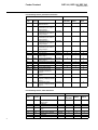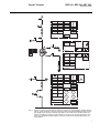
1
Feeder Terminal
Buyer’s Guide
REF 541,
REF 543,
REF 545.
Feeder Terminal
REF 541, REF 543, REF 545.
1MRS750443-MBG
Issued: June 1999
Status: Updated
Version: F/06.07.2005
Data subject to change without notice
Features
• Feeder terminal for protection, control,
measurement and supervision of medium
voltage networks.
• Additional functions including synchrocheck, frequency protection, capacitor
bank protection and control.
• Voltage and current measurement via conventional measuring transformers or current sensors and voltage dividers.
• RTD/analogue module for temperature
measurement, current/voltage measurement and mA-outputs.
• Fixed human-machine interface including a
large graphic display, or an external display
module for flexible switchgear installation.
• Communication over three communication
interfaces: one for local communication
with a PC and two for simultaneous dual
port communication for e.g. a substation
communication system and a substation
monitoring system.
• Protection functions including e.g. nondirectional and directional overcurrent and
earth-fault protection, residual voltage,
overvoltage and undervoltage protection,
thermal overload protection, CBFP and
auto-reclosing.
• Control functions including local and
remote control of switching objects with
synchro-check, status indication of the
switching objects and interlockings on bay
and station level
• Measurement of phase currents, phase-tophase and phase-to-neutral voltages, neutral current and residual voltage, frequency,
power factor, active and reactive power
and energy.
• Selectable function block naming: ANSI
device numbers, IEC symbols or ABB naming.
• Support for IEC 61850 protocol through the
SPA-ZC 400 adapter.
• Support for Profibus-DPV1 protocol
through the SPA-ZC 302 adapter
• Part of the ABB Distribution Automation
system.
• Advanced power quality measurement
capabilities. Total harmonic distortion
(THD) measurements for both currents and
voltages. Measurement for short duration
voltage variations like sags, swells and
short interruptions.
• Condition monitoring including circuitbreaker condition monitoring, trip circuit
supervision and internal self-supervision of
the feeder terminal.
• Time synchronization via binary input. Synchronization pulse once per second or
once per minute.
• Fault locator for short circuits in all kinds of
network and for earth-faults in effectively
earthed and low resistance/low reactance
earthed networks.
Fig. 1
Setting group example window.
3
Feeder Terminal
REF 541, REF 543, REF 545.
1MRS750443-MBG
Application
The REF 541, REF 543 and REF 545 feeder
terminals are designed to be used for protection, control, measurement and supervision of
medium voltage networks.
They can be used with different kinds of
switchgear including single busbar, double
busbar and duplex systems. The protection
functions also support different types of networks such as isolated neutral networks, resonant-earthed networks and partially earthed
networks..
Control room connection
RER 111 LON
star-coupler
Application area also covers protection functions for a large variety of applications, e.g.
frequency and voltage based protection,
motor protection, thermal overload protection, capacitor bank protection and synchrocheck/voltage check function.
In addition to protection, measurement, control and condition monitoring functions, the
feeder terminals are provided with a large
amount of PLC functions allowing several
automation and sequence logic functions
needed for substation automation to be integrated into one unit.
The data communication properties include
the following communications: SPA bus,
LON bus, IEC 60870-5-103, IEC 61850,
Profibus-DPV1, DNP 3.0 or Modbus communication with higher-level equipment. Further, LON communication, together with
PLC functions, minimizes the need for hardwiring between the units.
Optical LON bus
REF 541
21 kV
CB OK
AROFF
1MRS xxxxxx
Uaux = 80...265 Vdc/ac Ion = 1/5 A (Io)
98150
fn = 50 Hz
Un = 100/110 V (U)
In = 1/5 A (I)
Uon = 100/110 V (Uo) 9509
REF 541
REF 541
REF 541
21 kV
CB OK
21 kV
CB OK
21 kV
CB OK
AROFF
AROFF
1MRS xxxxxx
Uaux = 80...265 Vdc/ac Ion = 1/5 A (Io)
98150
fn = 50 Hz
Un = 100/110 V (U)
In = 1/5 A (I)
Uon = 100/110 V (Uo) 9509
Fig. 2
Design
AROFF
1MRS xxxxxx
Uaux = 80...265 Vdc/ac Ion = 1/5 A (Io)
98150
fn = 50 Hz
Un = 100/110 V (U)
In = 1/5 A (I)
Uon = 100/110 V (Uo) 9509
1MRS xxxxxx
Uaux = 80...265 Vdc/ac Ion = 1/5 A (Io)
98150
fn = 50 Hz
Un = 100/110 V (U)
In = 1/5 A (I)
Uon = 100/110 V (Uo) 9509
Distributed protection and control system
based on REF 54_ feeder terminals.
The feeder terminals REF 541, REF 543 and
REF 545 differ from each other regarding the
number of digital inputs and outputs available. Please, refer to section “Ordering” for
more details.
The REF 54_ feeder terminals incorporate a
wide range of feeder terminal functions:
• Protection functions
• Measurement functions
• Disturbance recorder
• Power quality functions
• Control functions
• Fault locator
• Condition monitoring functions
• General functions
• Communication functions
• Standard functions
The function blocks are documented on the
CD-ROM “Technical Descriptions of Functions” (1MRS 750889-MCD).
4
Protection functions
Protection is one of the most important functions of the REF 54_ feeder terminal. The
protection function blocks (e.g. NOC3Low)
are independent of each other and have e.g.
their own setting groups and data recording.
The non-directional overcurrent protection
includes e.g. the three stages NOC3Low,
NOC3High and NOC3Inst, each with independent protection functions.
Either Rogowski coils or conventional current transformers can be used for protection
functions based on current measurement.
Correspondingly, voltage dividers or voltage
transformers are used for protection functions
based on voltage measurement
For further information about functionality
levels and the protection functions included
in them, refer to the table “Functionality levels, protection functions” in section
“Ordering”.
Measurement functions
The measurement functions include threephase currents, neutral current, three-phase
voltages, residual voltage, frequency, active
Feeder Terminal
REF 541, REF 543, REF 545.
1MRS750443-MBG
and reactive power and power factor. In addition, other measurement functions are available.
As a standard feature the REF 54_ terminal
includes pulse counter inputs. The number of
pulse inputs varies from 7 (REF 541) to 10
(REF 545) according to the REF variant.
Disturbance recorder
The transient disturbance recorder is able to
record 16 current or voltage waveforms and
16 logic digital signals. The sampling frequency of the analogue inputs is 2 kHz at the
rated frequency of 50 Hz and 2.4 kHz at the
rated frequency of 60 Hz.
The user can set the length of a recording
within a range determined by the number of
analogue inputs used. The number of recordings depends on the sampling frequency,
length of recordings and number of analogue
inputs.
The recordings can be uploaded with a DRCollector Tool which converts the data to a
COMTRADE format. The DR-Collector Tool
is supported in CAP501 and CAP505 relay
tools.
MIMIC configuration picture displayed on
the HMI. Position indicators are used to indicate the position of switching devices via the
MIMIC picture and to control them locally.
The status of different objects, e.g. open/
close/undefined, displayed in the MIMIC
view can be freely designed.
Fault locator
The fault locator function for radial distribution systems. Short-circuit localization in all
kind of distribution networks. Earth-fault
localization in effectively earthed networks
and in low reactance/low resistance earthed
networks. Assists fast power restoration after
the fault. Improves system availability and
performance.
Condition monitoring functions
Condition monitoring function blocks such as
supervision of the energizing current and
voltage input circuit, operation time counter,
circuit breaker electric wear, scheduled maintenance, trip circuit supervision and breaker
travel time are available for the REF 54_
feeder terminals.
General functions
Power quality functions
Power quality functions enable measurement
of total harmonic distortion (THD) of voltage
and current, and total demand distortion
(TDD) of current. Individual harmonics are
measured up to 13th.
Power quality functions also include measurement of short duration voltage variations
like sags, swells and short interruptions. Measurements are done according to the IEC standard 61000-4-30.
LIB 510 supports tools for presentation of
harmonics and short duration voltage variations.
Control functions
The control functions are used to indicate the
position of switching devices, i.e. circuit
breakers and disconnectors, and to execute
open and close commands for controllable
switching devices in the switchgear. Furthermore, there are supplementary functions for
control logic purposes, e.g. on/off switches,
MIMIC alarm, LED control, numerical data
for the MIMIC and logic controlled position
selection.
The control functions configured using the
Relay Configuration Tool can be associated
with position indicators that are part of the
Additional functions are available for different general purposes to be used in logics such
as activation of HMI backlight, switchgroups,
and resetting of operation indications, latched
output signals, registers and disturbance
recorder.
Communication functions
The REF 54_ feeder terminal provides the
IEC 60870-5-103, IEC 61850, ProfibusDPV1, Modbus, DNP 3.0, SPA and LON
serial communication protocols.
In a customer-specific feeder terminal configuration, special events can be generated via
an EVENT230 event function.
Standard functions
Standard functions are used for logics such as
interlocking, alarming and control sequencing. The use of logic functions is not limited
and the functions can be interconnected with
each other as well as with protection, measurement, power quality, control, condition
monitoring and general functions. In addition,
the digital inputs and outputs as well as LON
inputs and outputs can be connected to standard functions by using the Relay Configuration Tool.
5
Feeder Terminal
REF 541, REF 543, REF 545.
1MRS750443-MBG
Other functions
Low auxiliary voltage indication
The REF 54_ feeder terminal is provided
with a low auxiliary voltage indication feature. The power supply module issues an
internal alarm signal when a drop in the
power supply voltage is detected (ACFail,
active low). The alarm signal is activated if
the power supply voltage falls about 10%
below the lowest rated DC input voltage of
the power supply module.
The indication of a low auxiliary voltage is
available in the feeder terminal configuration
and can be connected to any signal output of
the REF 54_.
Overtemperature indication
The REF 54_ feeder terminal includes an
internal temperature supervision function.
The power supply module issues an internal
alarm signal when overtemperature has been
detected inside the terminal enclosure. The
alarm signal will be activated once the temperature inside the terminal enclosure
increases to +78°C (+75°...+83°C). Overtemperature indication is available in the
feeder terminal configuration and can be connected to any signal output of the terminal.
Analog channels
The feeder terminal measures the analogue
signals needed for protection, measuring, etc.
via sensors or galvanically separated matching transformers.
Depending on whether sensors are included
or not, REF 54_ feeder terminals have 9
(without sensors) or 10 (with sensors) analogue channels. The number of channels used
depends on the feeder terminal configuration
and the kind of matching transformers or sensor inputs used. Furthermore, the feeder terminal includes virtual analogue channels for
calculating the phase-to-phase voltages, neutral current and residual voltage from phase
currents and voltages.
In addition to 9 conventional matching transformers, sensors developed by ABB can be
used parallel in REF 54_ feeder terminals.
The feeder terminal has 9 sensor inputs. A
current sensor (Rogowski coil) or a voltage
divider can be connected to each sensor input.
Please, see the connection diagram for
details. When ordering, please note the type
of analogue inputs.
6
Each analog channel is separately configured
with the Relay Configuration Tool. Both the
measuring unit for each analog channel and
the type of signal to be measured are to be
configured.
A separate scaling factor can be set for each
analogue channel. The factors enable differences between the ratings of the protected
unit and those of the measuring device (CTs,
VTs etc.). The setting value 1.00 means that
the rated value of the protected unit is exactly
the same as that of the measuring device.
Calculated analogue channels
The REF 54_ feeder terminal includes virtual
channels to obtain phase-to-phase voltages,
neutral current and residual voltage when
sensors are used. Sensors are connected to the
feeder terminal via coaxial cables and therefore a residual connection of phase currents
or an open-delta connection of phase voltages
cannot be made. Both the amplitude and the
phase angle are calculated for the virtual
channels.
Though primarily meant to be used with sensors, the calculated analogue channels can
also be used with conventional current and
voltage transformers.
Note! When sensitive earth-fault protection is
needed, core balance transformers are not
recommended to be replaced with the numerically derived sum of phase currents. Normally, an earth-fault setting below 10% of the
rated value requires the use of a core balance
transformer.
Digital inputs
The digital inputs of the feeder terminals are
voltage-controlled and optically isolated. The
function of a digital input can be inverted.
The programmable filter time removes
debounces and short disturbances on a digital
input. The filter time can be set for each digital input separately.
Some specific digital inputs can be programmed to operate either as digital inputs, as
pulse counters or as used for time synchronization. When a digital input operates as a
pulse counter, pulse counting frequency can
be up to100 Hz.
Oscillation suppression
The feeder terminals have two global parameters for the suppression of digital input oscillation. The settings of these parameters
Feeder Terminal
REF 541, REF 543, REF 545.
1MRS750443-MBG
determine the oscillation level and hysteresis
for all digital inputs. Event is generated in
case oscillation is detected.
Attributes of a digital input for feeder terminal configuration
For each digital input, the status of the input
(value), the time tag for the status change
(time) and the validity of the digital input
(invalidity) can be issued by the attributes.
These attributes are available in the feeder
terminal configuration and can be used for
various purposes.
RTD/analogue inputs
The REF 541 and REF 543 feeder terminals
equipped with an RTD/analogue module
(RTD1) have eight general purpose analogue
inputs for DC measurement. The RTD/analogue inputs are galvanically isolated from
the feeder terminal power supply and enclosure. However, the inputs have a common
ground. The general purpose RTD/analogue
inputs accept voltage-, current- or resistancetype signals. For each measuring mode, a
separate parameter is provided for choosing
between the available measurement ranges.
RTD/analogue inputs can be applied for e.g.
temperature measurement.
Digital outputs
The outputs of the feeder terminal are categorized as follows:
• HSPO: High-speed power output, doublepole contact, preferred for tripping purposes and for circuit breaker and disconnector control
• PO: Power output, either single-pole or
double-pole contact, preferred for circuit
breaker and disconnector control
• SO: Signal output, either NO (Normally
Open) or NO/NC (Normally Open/Normally Closed) contact. The output contact
is a normal-duty contact and cannot be
used for controlling a heavy load such as a
circuit breaker.
Analogue outputs
The REF 541 and REF 543 feeder terminals
equipped with an RTD/analogue module have
four general purpose 0...20 mA analogue current outputs. All outputs are galvanically isolated from the supply and enclosure of the
feeder terminal and from each other.
Analogue outputs can be utilized for transferring any measured or calculated information
to panel meters or e.g. PLCs.
Alarm LED indicators
The feeder terminal offers eight alarm LED
indicators to be configured with the Relay
Mimic Editor. The LED colours (green, yellow, red), their use, and the ON and OFF state
texts can be freely defined. Three basic operation modes are supported: non-latched,
latched-steady and latched flashflashing.
Alarms can be acknowledged remotely,
locally or by using logic of the feeder terminal.
The alarm channels include time tagging for
detected alarms. The time tagging principle
used depends on the operation mode.
Interlocking LED indicator
The interlocking LED indicates that control
operation has been interlocked or that the
interlocking is in bybass mode, e.g. when
control is possible despite of interlocking.
Trip Circuit Supervision
The purpose of this function is to supervise
the tripping circuitry of the circuit breaker.
An alarm will be generated in case a faulty
tripping circuit, e.g. a circuit is not able to
perform a trip, is detected.
The supervision is based on the constant-current injection through the tripping circuitry.
Display panel
The feeder terminal is provided with either a
fixed display or an external display module.
The external display module requires a separate voltage supply from a common source
with the main unit. The display consists of 19
rows divided into two windows: a main window (17 rows) and an assisting window
(2 rows).
The graphic display presents detailed information on MIMIC, objects, events, measurements, control alarms, and parameters. The
assisting window is used for terminal-dependent indications/alarms and help messages.
Additionally, the panel includes the following
HMI items:
• three push-buttons for object control (I, O,
object selection)
• eight freely programmable alarm LEDs
with different colours and modes according to the configuration
• LED indicator for control interlocking
• three protection LED indicators
• HMI push-button section with four arrow
buttons and buttons for clear and enter
7
Feeder Terminal
REF 541, REF 543, REF 545.
1MRS750443-MBG
• optically isolated serial communication
port
• backlight and contrast control
• freely programmable button (F) which can
be used in the configuration of the feeder
terminal
• a button for remote/local control
HMI has two main levels, the user level and
the technical level. The user level is for
“everyday” measurements and monitoring
whereas the technical level is intended for
advanced feeder terminal programming.
Serial communication
The feeder terminal has three serial communication ports, one on the front panel and two
on the rear panel.
Front panel optical connection for PC
The front panel is intended for the connection
of a PC for configuring the feeder terminal
with the CAP 50_ tools. The front interface
uses the SPA bus protocol.
The optical connector on the front panel isolates the PC galvanically from the feeder terminal. The front connector for the PC is
standardized for ABB relay products and
requires a specific opto cable. The cable is
connected to the serial RS-232 port of the PC.
The other communication parameters for the
rear RS-485 interface are also set in the Communication menu of the REF 54_ feeder terminal.
SPA/IEC_103 communication on the rear
connector X3.2
The 9-pin D-type subminiature male connector (RS-232 connection) on the rear panel
connects the feeder terminal to the distribution automation system via the SPA bus or the
IEC_103. The fibre-optic interface module
type RER 123 is used for connecting the
feeder terminal to the fibre-optic communication bus for SPA and IEC_103 protocol.
DNP3.0/Modbus communication on the
rear connector X3.2
The 9-pin D-type subminiature male connector (RS-232 connection) on the rear panel
connects the feeder terminal to the distribution automation system via the DNP 3.0 or
the Modbus protocol. The interface between
the feeder terminal and a RS-485 communication bus can be made through the RER 133
Bus Connection Module. The interface
between the feeder terminal and an optical
bus can be made through the RER 123 Bus
Connection Module.
8
IEC 61850 communication using SPA-ZC
400 on the rear connector X3.2
The 9-pin D-type subminiature male connector (RS-232 connection) on the rear panel
connects the feeder terminal to the distribution automation system via the IEC 61850
protocol. In the IEC 61850 mode, the SPAZC 400 Bus Connection Module is needed.
Profibus-DPV1 communication using SPAZC 302 on the rear connector X3.2
The 9-pin D-type subminiature male connector (RS-232 connection) on the rear panel
connects the feeder terminal to the distribution automation system via the Profibus protocol. The interface between the feeder
terminal and Profibus can be made through
the SPA-ZC 302 Gateway.
LON/SPA bus communication on the rear
connector X3.3
The 9-pin D-type subminiature female connector (RS-485 connection) on the rear panel
connects the feeder terminal to the substation
automation system via the SPA bus or the
LON bus. The fibre-optic interface module
type RER 103 is used to connect the feeder
terminal to the fibre-optic communication
bus. The RER 103 module supports both SPA
bus and LON bus communication.
Self-supervision
The feeder terminal REF 54_ is provided
with an extensive self-supervision system.
The self-supervision system handles run-time
fault situations and informs the user of faults
via the HMI and LON/SPA bus communication.
When a fault has been detected, the green
Ready indicator starts flashing, a fault indication text is displayed on the HMI and an
event 0/E57 is generated. The fault indication
text on the HMI consists of two rows: a general message ‘internal fault’, followed by the
generated IRF code of the fault.
The relay will try to recover from a fault
either by restarting the module (I/O module
or HMI) that reported the fault, or by restarting the whole relay. During restarting the IRF
state will remain active until the internal selfsupervision program has determined that the
relay is operating normally. If the fault is still
persistent after restarting three times, the
relay will be in permanent IRF state.
Feeder Terminal
REF 541, REF 543, REF 545.
1MRS750443-MBG
Feeder terminal configuration
Lon network configuration
The Relay Configuration Tool, based on the
IEC 61131-3 standard, is used for configuring
the basic terminal, protection and logic function blocks, control and measurement functions, timers and other functional elements
included in the logic functions category.
The LON Network Tool is used for binding
network variables between RED 500 terminals. Typically, LON is used for transferring
object status data (open, close, undefined)
between units for interlocking sequences running in the units.
The programmable system of REF 54_ feeder
terminals allows the output contacts to be
operated in accordance with the state of the
logic inputs and the outputs of the protection,
control, measurement and condition monitoring functions. The PLC functions (e.g. interlocking and alarm logic) are programmed
with Boolean functions, timers, counters,
comparators and flip-flops. The program is
written in a function block diagram language
by using the configuration software.
DNP 3.0 and Modbus configuration
Mimic configuration
The control functions configured using the
Relay Configuration Tool can be associated
with position indicators that are part of the
MIMIC configuration picture displayed on
the graphic LCD of the HMI. The MIMIC
configuration picture is designed with the
Relay Mimic Editor. In addition, the editor is
used to define the eight programmableLED
indicators and the corresponding alarm texts
on the front panel, the alarm modes, and the
interlocking LED texts.
The MIMIC picture may include a single-line
diagram, measured values with units, free
texts, etc. The position indicators (open,
closed, undefined) are drawn according to the
customer's requirements. Note that the operation of the objects themselves is determined
by means of the Relay Configuration Tool.
All of the eight alarm function blocks can be
configured in the same alarm view of the
mimic editor. ON and OFF state texts (only
one language version at a time can be supported for the alarm) and LED colours can be
defined. Three different colours can be used
to define the ON and OFF state. Three basic
modes are available:
• non-latched
• latched-steady
• latched flashing
Interlocking LED texts can also be defined in
the same alarm view but the colour of the
interlocking LED cannot be changed.
The Protocol Mapping Tool included in the
CAP 505 is used for configuring the DNP 3.0
and Modbus interfaces of the feeder terminal.
Feeder terminal
parameterization
The parameters of the feeder terminal units
can be set either locally over the HMI or
externally via the serial communication.
Local parameterization
When the parameters are set locally via the
HMI, the setting parameters can be chosen
from the hierarchical menu structure. The
desired language for parameter description
can be selected.
External parameterization
The Relay Setting Tool is used for parameterizing and setting the feeder terminals externally. The parameters can be set off-line on a
PC and downloaded to the feeder terminal
over a communication port. The menu structure of the setting tool, including views for
parameterization and settings, is the same as
the menu structure of the feeder terminal.
Terminal connections
All external circuits are connected to the terminal blocks on the rear panel. The terminal
block for the measuring transformers consists
of fixed screw terminals.
ABB sensors (Rogowski coil or voltage
divider) are connected to the feeder terminal
with special type of shielded twin BNC connectors. This type of connectors are used to
improve reliability and protection against disturbances. Unused sensor inputs must be
short-circuited with special connectors, type
1MRS 120515.
The RS232 serial interface on the rear panel
is used to connecting the feeder terminal to
the SPA, the IEC_103, Modbus, DNP 3.0,
Profibus, or IEC 61850 bus. The SPA,
IEC_103, Modbus and DNP 3.0 bus is connected through RER 123 Bus Connection
Module. DNP 3.0/Modbus can also be connected through the RER 133 Bus Connection
Module.
9
Feeder Terminal
REF 541, REF 543, REF 545.
1MRS750443-MBG
Profibus is available through the SPA-ZC 302
Gateway and IEC 61850 is available through
the SPA-ZC 400 Ethernet Adapter
The digital input and output contacts of the
feeder terminal are connected to the multipole connectors.
The serial interface RS-485 on the rear panel
is used for connecting the feeder terminal to
the SPA bus or the LON bus. The SPA/LON
bus is connected via the RER 103 Connection
Module fitted to the 9-pin D-type subminiature connector and screwed to the rear panel.
Protective earth is connected to the screw
marked with the earth symbol.
Basic connection diagrams
+
+
Q1
A
Q0
N
L1
L3
0
-
n
*)
+
+
Q9
a
da
PS1_4_ACFail
dn
P1
L3
L1
25
24
S1
22
21
S2
P2
19
18
16
15
14
13
12
11
10
9
8
7
6
5
4
3
2
1
S1
S2
1
-
2
PS1_4_TempAlarm
X1.1
27
X2.1
X2.2
X2.3
100V
Ch 10, VT4
100V
Ch 9, VT3
100V
Ch 8, VT2
100V
Ch 7, VT1
X2.7
X2.8
X2.9
I
X3.2
X3.3
X4.1
3
4
IRF
Ch 6, CT5
5
Ch 5, CT4
1A
5A
Ch 4, CT3
7
9
8
PS1_4_HSPO3
10
1A
5A
Ch 3, CT2
1A
5A
Ch 2, CT1
PS1_4_HSPO1
PS1_4_TCS1
TCS1
11
13
12
15
DIFF
DIFF
DIFF
DIFF
X2.6
-
6
1A
5A
X2.4
X2.5
SERIAL BUS
SERIAL BUS
0,2A
1A
X4.1
Mains
DIFF
DIFF
DIFF
DIFF
DIFF
Ch 10, sensor
Ch 9, sensor
PS1_4_HSPO2
PS1_4_TCS2
TCS2
16
18
17
+
+
External
open
0
+
+
1
**)
External
close
Ch 8, sensor
Ch 7, sensor
X4.2
8
Ch 5, sensor
Ch 4, sensor
Ch 3, sensor
PS1_4_HSPO4
9
11
10
12
Ch 2, sensor
Ch 1, sensor
PS1_4_HSPO5
13
15
14
Disconnector Q1
Close
Disconnector Q1
Open
16
17
X4.2
1
2
-
PS1_4_BI2
6
7
PS1_4_BI3
X5.1
1
2
3
BIO1_5_BI1
-
4
5
6
-
7
8
9
PS1_4_SO1
PS1_4_BI1
4
5
18
X5.2
3
BIO1_5_SO1
4
5
BIO1_5_BI2
BIO1_5_SO2
BIO1_5_BI3
6
7
9
BIO1_5_BI4
BIO1_5_SO3
BIO1_5_BI5
8
10
12
BIO1_5_BI6
*) Power flow direction
**) Example connection
10
11
12
13
14
15
16
17
18
BIO1_5_SO4
BIO1_5_BI7
11
13
15
BIO1_5_BI8
BIO1_5_SO5
BIO1_5_BI9
BIO1_5_BI10
BIO1_5_SO6
14
16
18
17
BIO1_5_BI11
X5.2
1
2
BIO1_5_BI12
REF 541
(1MRS 090115-AABA/BABA/CABA)
A050202
Fig. 3
10
Basic connection diagram of REF 541.
Feeder Terminal
REF 541, REF 543, REF 545.
1MRS750443-MBG
+
Q1
+
+
Q2
A
Q0
+
L3
0
N
Q3
n
*)
+
L1
a
Q9
X4.1
dn
PS1_4_TempAlarm
X1.1
27
P1
L1
L3
25
24
S1
22
21
S2
P2
+
Mains 1
2
-
PS1_4_ACFail
da
19
18
16
15
14
13
12
11
10
9
8
7
6
5
4
3
2
1
S1
S2
100V
Ch 10, VT4
100V
Ch 9, VT3
100V
Ch 8, VT2
100V
Ch 7, VT1
SERIAL BUS
0,2A
1A
1A
5A
1A
5A
1A
5A
1A
5A
Ch 2, CT1
DIFF
Ch 10, sensor
DIFF
Ch 9, sensor
DIFF
Ch 8, sensor
X2.3
X2.4
DIFF
Ch 7, sensor
DIFF
Ch 5, sensor
DIFF
Ch 4, sensor
X2.5
X2.6
X2.7
DIFF
Ch 3, sensor
DIFF
Ch 2, sensor
Ch 1, sensor
X3.3
5
6
7
9
8
PS1_4_HSPO3
10
Ch 3, CT2
X2.2
X2.8
IRF
Ch 6, CT5
Ch 4, CT3
X3.2
X4.1
3
4
Ch 5, CT4
X2.1
X2.9
SERIAL BUS
I
PS1_4_HSPO1
PS1_4_TCS1
TCS1
11
13
12
15
PS1_4_HSPO2
PS1_4_TCS2
TCS2
16
18
17
+ _
_
**)
+ _
+
_
External
open
0
1
External
close
+
X4.2
8
PS1_4_HSPO4
PS1_4_HSPO5
DIFF
9
11
10
12
Disconnector Q1
Close
Disconnector Q1
Open
13
15
14
16
17
X4.2
1
2
PS1_4_BI1
4
5
PS1_4_BI2
6
7
PS1_4_BI3
PS1_4_SO1
X5.2
3
X5.1
-
1
2
3
-
4
5
6
-
-
7
8
9
10
11
12
13
14
15
16
17
18
BIO1_5_BI1
BIO1_5_SO1
BIO1_5_BI2
BIO1_5_BI3
BIO1_5_SO2
BIO1_5_BI4
BIO1_5_BI5
BIO1_5_SO3
4
5
6
7
9
8
10
12
BIO1_5_BI6
BIO1_5_BI7
BIO1_5_SO4
11
13
15
BIO1_5_BI8
BIO1_5_BI9
BIO1_5_SO5
14
BIO1_5_SO6
17
BIO1_5_BI10
BIO1_5_BI11
16
18
X7.1
X5.2
1
2
18
BIO1_5_BI12
BIO2_7_PO1
17
18
X7.2
X7.1
-
*) Power flow direction
**) Example connection
1
2
3
4
5
6
7
8
9
10
11
12
BIO2_7_BI1
BIO2_7_PO2
1
2
BIO2_7_PO3
4
5
6
BIO2_7_PO4
8
9
10
BIO2_7_PO5
12
13
14
BIO2_7_PO6
16
17
18
3
BIO2_7_BI2
BIO2_7_BI3
7
BIO2_7_BI4
BIO2_7_BI5
BIO2_7_BI6
BIO2_7_BI7
11
BIO2_7_BI8
13
14
BIO2_7_BI9
15
16
BIO2_7_BI10
Disconnector Q2
Close
Disconnector Q2
Open
Disconnector Q3
Close
15
Disconnector Q3
Open
REF 543
(1MRS 090127-AABA/BABA/CABA)
A050203
Fig. 4
Basic connection diagram of REF 543.
11
Feeder Terminal
REF 541, REF 543, REF 545.
1MRS750443-MBG
+
Q1
+
+
Q2
A
Q0
+
L3
0
N
Q3
n
*)
+
L1
a
Q9
da
L1
L3
25
24
S1
22
21
S2
P2
19
18
16
15
14
13
12
11
10
9
8
7
6
5
4
3
2
1
S1
S2
Mains
100V
Ch 10, VT4
100V
Ch 9, VT3
100V
Ch 8, VT2
100V
Ch 7, VT1
0,2A
1A
X2.4
X2.5
X2.6
X2.7
X2.8
X2.9
-
-
4
5
6
-
7
8
9
-
10
11
12
1A
5A
Ch 4, CT3
1A
5A
X3.2
X3.3
3
4
IRF
5
7
9
8
PS2_4_HSPO3
10
Ch 3, CT2
1A
5A
Ch 2, CT1
DIFF
Ch 10, sensor
DIFF
Ch 9, sensor
DIFF
Ch 8, sensor
DIFF
Ch 7, sensor
DIFF
DIFF
PS2_4_HSPO1
PS2_4_TCS1
+ _
PS2_4_TCS2
Ch 4, sensor
Ch 3, sensor
DIFF
Ch 2, sensor
BIO1_5_BI1
7
8
9
10
11
12
13
14
15
16
17
18
4
5
6
7
8
9
10
11
12
+ _
1
External
close
Disconnector Q1
Close
6
8
7
9
10
12
11
PS2_4_HSPO8
17
18
Disconnector Q1
Open
Disconnector Q2
Close
Disconnector Q2
Open
BIO1_5_BI5
X5.2
3
BIO1_5_BI6
BIO1_5_BI7
BIO1_5_SO1
4
5
BIO1_5_BI8
BIO1_5_BI9
BIO1_5_SO2
6
7
9
BIO1_5_BI10
BIO1_5_BI11
BIO1_5_SO3
BIO1_5_SO4
BIO1_5_BI12
BIO1_6_BI1
BIO1_6_BI2
BIO1_5_SO6
BIO1_6_SO1
BIO1_6_BI5
BIO1_6_BI6
BIO1_6_SO2
BIO1_6_BI7
BIO1_6_SO3
BIO1_6_BI8
BIO1_6_BI9
BIO1_6_SO4
BIO1_6_BI10
BIO1_6_BI11
BIO1_6_BI12
11
13
15
14
16
18
17
3
BIO1_6_BI3
BIO1_6_BI4
8
10
12
X6.2
BIO1_6_SO5
BIO1_6_SO6
4
5
6
7
9
8
10
12
11
13
15
14
16
18
17
X7.1
X7.1
1
2
3
2
4
3
14
16
15
BIO1_5_BI3
X6.2
1
2
+
13
BIO1_5_SO5
4
5
6
TCS2
16
18
17
PS2_4_HSPO7
X6.1
1
2
3
15
_
+
5
PS2_4_HSPO5
PS2_4_HSPO6
X5.2
1
2
**)
11
13
12
1
DIFF
BIO1_5_BI4
External
open
0
X4.2
PS2_4_HSPO4 *)
Ch 1, sensor
BIO1_5_BI2
_
TCS1
PS2_4_HSPO2
Ch 5, sensor
DIFF
13
14
15
16
17
18
*) Power flow direction
2
X4.1
Ch 6, CT5
X5.1
1
2
3
SERIAL BUS
I
1
Ch 5, CT4
X2.2
X2.3
SERIAL BUS
X4.1
6
1A
5A
X2.1
-
-
PS2_4_TempAlarm
X1.1
27
P1
+
PS2_4_ACFail
dn
BIO2_7_BI1
BIO2_7_PO1
BIO2_7_BI3
17
18
X7.2
BIO2_7_BI2
BIO2_7_PO2
1
2
3
BIO2_7_BI4
BIO2_7_BI5
BIO2_7_PO3
BIO2_7_BI6
BIO2_7_BI7
BIO2_7_PO4
BIO2_7_BI8
13
14
BIO2_7_BI9
15
16
BIO2_7_BI10
BIO2_7_PO5
BIO2_7_PO6
REF 545
(1MRS 090133-AABA/BABA/CABA)
4
5
6
7
8
9
10
11
Disconnector Q3
Close
Disconnector Q3
Open
12
13
14
15
16
17
18
A050204
Fig. 5
12
Basic connection diagram of REF 545.
Feeder Terminal
REF 541, REF 543, REF 545.
1MRS750443-MBG
X6.1
1
2
3
4
5
6
7
8
9
10
11
12
13
14
15
16
17
18
SHUNT
+
-
X6.2
DIFF
SHUNT
+
DIFF
+
-
DIFF
RTD1_6_AI1
RTD1_6_AO1
+
mA-
11
12
RTD1_6_AO2
+
mA-
13
14
RTD1_6_AI3
RTD1_6_AO3
+
mA-
15
16
RTD1_6_AI4
RTD1_6_AO4
+
mA-
17
18
RTD1_6_AI2
SHUNT
SHUNT
+
DIFF
+
-
DIFF
SHUNT
RTD1_6_AI5
X6.2
1
2
3
4
5
6
7
8
9
10
SHUNT
+
DIFF
+
-
DIFF
RTD1_6_AI6
SHUNT
SHUNT
+
DIFF
RTD1_6_AI7
RTD1_6_AI8
A050205
Fig. 6
Terminal diagram of the RTD/analog module
Auxiliary voltage
For its operation, the REF 54_ terminal,
including the external display module,
requires a secured auxiliary voltage supply.
The feeder terminal’s internal power supply
module forms the voltages required by the
feeder terminal electronics. The power supply
module is a galvanically isolated (fly-back
type) dc/dc converter. A green protection
LED indicator on the front panel is lit when
the power supply module is in operation.
The feeder terminal is provided with a 48hour capacitor back-up protection that
enables the internal clock to keep time in case
of an auxiliary power failure.
Power supply
There are two basic types of power supply
modules available for the REF 54_: type
PS1/_ and type PS2/_. See Tecnical data table
9.The operating range of digital inputs
depends on the type of the power supply
module. See Technical data table 10.
13
Feeder Terminal
REF 541, REF 543, REF 545.
1MRS750443-MBG
Technical data
.
Table 1: General functions
Function
Description
INDRESET
Resetting of operation indicators, latched output signals, registers
and waveforms i.e. the disturbance recorder
MMIWAKE
Activation of HMI backlight
SWGRP1
Switchgroup SWGRP1
SWGRP2
Switchgroup SWGRP2
SWGRP3
Switchgroup SWGRP3
...
...
SWGRP20
Switchgroup SWGRP20
Table 2: Standard functions
14
Function
Description
ABS
Absolute value
ACOS
Principal arc cosine
ADD
Extensible adder
AND
Extensible AND connection
ASIN
Principal arc sine
ATAN
Principal arc tangent
BITGET
Get one bit
BITSET
Set one bit
BOOL_TO_*
Type conversion from BOOL to WORD / USINT / UINT / UDINT /
SINT / REAL / INT / DWORD / DINT / BYTE
BOOL2INT
Type conversion from BOOL inputs to INT output
BYTE_TO_*
Type conversion from BYTE to WORD / DWORD
COMH
Hysteresis comparator
COS
Cosine in radians
CTD
Down-counter
CTUD
Up-down counter
CTU
Up-counter
DATE_TO_UDINT
Type conversion from DATE to UDINT
DINT_TO_*
Type conversion from DINT to SINT / REAL / INT
DIV
Divider
DWORD_TO_*
Type conversion from DWORD to WORD / BYTE
EQ
Extensible comparison to equal
EXP
Natural exponential
EXPT
Exponentiation
F_TRIG
Falling edge detector
GE
Extensible comparison to greater or equal
GT
Extensible comparison to greater
INT_TO_*
Type conversion from INT to REAL / DINT
INT2BOOL
Type conversion from INT input to BOOL outputs
LE
Extensible comparison to less or equal
LIMIT
Limitation
LN
Natural logarithm
LOG
Logarithm base 10
LT
Extensible comparison to less
MAX
Extensible maximum
MIN
Extensible minimum
MOD
Modulo
MOVE
Move
MUL
Extensible multiplier
MUX
Extensible multiplexer
Feeder Terminal
REF 541, REF 543, REF 545.
1MRS750443-MBG
Table 2: Standard functions
Function
Description
NE
Comparison to greater or less
NOT
Complement
OR
Extensible OR connection
R_TRIG
Rising edge detector
REAL_TO_*
Type conversion from REAL to USINT / UINT / UDINT / SINT / INT /
DINT
ROL
Rotate to left
ROR
Rotate to right
RS
Reset dominant bistable function block
RS_D
Reset dominant bistable function block with data input
SEL
Binary selection
SHL
Bit-shift to left
SHR
Bit-shift to right
SIN
Sine in radians
SINT_TO_*
Type conversion from SINT to REAL / INT / DINT
SUB
Subtractor
SQRT
Square root
SR
Set dominant bistable function block
XOR
Extensible exclusive OR connection
TAN
Tangent in radians
TIME_TO_*
Type conversion from TIME to UDINT / TOD / REAL
TOD_TO_*
Type conversion from TOD to UDINT / TIME / REAL
TOF
Off-delay timer
TON
On-delay timer
TP
Pulse
TRUNC_*
Truncation toward zero
UDINT_TO_*
Type conversion from UDINT to USINT / UINT / REAL
UINT_TO_*
Type conversion from UINT to USINT / UDINT / REAL / BOOL
USINT_TO_*
Type conversion from USINT to UINT / UDINT / REAL
WORD_TO_*
Type conversion from WORD to DWORD / BYTE
Table 3: Condition monitoring functions
Function
ANSI
IEC
device no. symbol
Description
CMBWEAR1 CB wear1
CB wear1 Circuit-breaker electric wear 1
CMBWEAR2 CB wear2
CB wear2 Circuit-breaker electric wear 2
CMCU3
MCS 3I
MCS 3I
Supervision function of the energizing current input circuit
CMGAS1
CMGAS1
GAS1
Gas pressure monitoring
CMGAS3 1)
CMGAS3
GAS3
Three-pole gas pressure monitoring
CMSCHED
CMSCHED SCHED
Scheduled maintenance
CMSPRC1
CMSPRC1 SPRC1
Spring charging control 1
CMTCS1
TCS1
TCS1
Trip circuit supervision 1
CMTCS2
TCS2
TCS2
Trip circuit supervision 2
CMTIME1
TIME1
TIME1
Operate time counter 1 for the operate time used (e.g. motors)
CMTIME2
TIME2
TIME2
Operate time counter 2 for the operate time used (e.g. motors)
CMTRAV1
CMTRAV1 TRAV1
Breaker travel time 1
CMVO3
MCS 3U
Supervision function of the energizing voltage input circuit
MCS 3U
1) This function is only supported in the feeder terminal
revisions of Release 2.0 or later.
15
Feeder Terminal
REF 541, REF 543, REF 545.
1MRS750443-MBG
.
Table 4: Control functions
Function
ANSI
IEC symbol
device no.
Description
CO3DC1
CO3DC1
I<->O 3DC1
Three-state disconnector (1) with indication
CO3DC2
CO3DC2
I<->O 3DC2
Three-state disconnector (2) with indication
COCB1
COCB1
I<->O CB1
Circuit breaker 1 control with indication
COCB2
COCB2
I<->O CB2
Circuit breaker 2 control with indication
COCBDIR
COCBDIR
CBDIR
Direct open for CBs via HMI
CODC1
CODC1
I<->O DC1
Disconnector 1 control with indication
CODC2
CODC2
I<->O DC2
Disconnector 2 control with indication
CODC3
CODC3
I<->O DC3
Disconnector 3 control with indication
CODC4
CODC4
I<->O DC4
Disconnector 4 control with indication
CODC5
CODC5
I<->O DC5
Disconnector 5 control with indication
COIND1
COIND1
I<->O IND1
Switching device 1 indication
COIND2
COIND2
I<->O IND2
Switching device 2 indication
COIND3
COIND3
I<->O IND3
Switching device 3 indication
COIND4
COIND4
I<->O IND4
Switching device 4 indication
COIND5
COIND5
I<->O IND5
Switching device 5 indication
COIND6
COIND6
I<->O IND6
Switching device 6 indication
COIND7
COIND7
I<->O IND7
Switching device 7 indication
COIND8
COIND8
I<->O IND8
Switching device 8 indication
COLOCAT
COLOCAT
I<->O POS
Logic-controlled control position selector
COPFC 1)
55
COPFC
Power factor controller
COSW1
COSW1
SW1
On/off switch 1
COSW2
COSW2
SW2
On/off switch 2
COSW3
COSW3
SW3
On/off switch 3
COSW4
COSW4
SW4
On/off switch 4
MMIALAR1 ALARM1
ALARM1
Alarm channel 1, LED indicator
MMIALAR2 ALARM2
ALARM2
Alarm channel 2, LED indicator
MMIALAR3 ALARM3
ALARM3
Alarm channel 3, LED indicator
MMIALAR4 ALARM4
ALARM4
Alarm channel 4, LED indicator
MMIALAR5 ALARM5
ALARM5
Alarm channel 5, LED indicator
MMIALAR6 ALARM6
ALARM6
Alarm channel 6, LED indicator
MMIALAR7 ALARM7
ALARM7
Alarm channel 7, LED indicator
MMIALAR8 ALARM8
ALARM8
Alarm channel 8, LED indicator
MMIDATA1 MMIDATA1 MMIDATA1
MIMIC data monitoring point 1
MMIDATA2 MMIDATA2 MMIDATA2
MIMIC data monitoring point 2
MMIDATA3 MMIDATA3 MMIDATA3
MIMIC data monitoring point 3
MMIDATA4 MMIDATA4 MMIDATA4
MIMIC data monitoring point 4
MMIDATA5 MMIDATA5 MMIDATA5
MIMIC data monitoring point 5
1) This function is only supported in the feeder terminal
revisions of Release 2.0 or later.
16
Feeder Terminal
REF 541, REF 543, REF 545.
1MRS750443-MBG
Power factor controller settings
Power factor controller, COPFC
The number of capacitor banks to be controlled
The relational step sizes and the type of the switching
sequence
Size of the first capacitor bank (should be the smallest)
Target value for daytime cos ϕ
Day unit
Target value for night-time cos ϕ
Night unit
Setting the reconnection inhibit time (discharge time)
Sensitivity in the inductive side
Sensitivity in the capacitive side
Alarm limit for the maximum reactive power
Alarm limit for the minimum reactive power
Overvoltage limit when the switching in is inhibited
Operation mode
Starting the automatic testing sequence
Calculation method
Control principle
Duration demand
Day&night switch
Manual command
1...4
1:1:1:1 linear; 1:1:1:1 circul.; 1:1:2:2 circul.;
1:2:2:2 linear; 1:2:2:2 circul.; 1:2:4:4 linear;
1:2:4:4 circul.; 1:2:4:8
10.0...50000.0 kvar
0.70...1.00
Inductive; Capacitive
0.70...1.00
Inductive; Capacitive
0.5...6000.0 s
60.0...200.0%
0.0...100.0%
0.1...100.0 Mvar
-100.0...0.0 Mvar
0.80...1.60 x Un
Not in use; Automatic mode; Manual mode;
Testing mode
Not activated; Start
Normal; Integral
Progressive; Direct
0.5...6000.0 s
Not in use; Digital input; Internal clock;
By setting
Not activated; Remove one step; Add one
step; Disconnect all
Recorded data
Number of switching operations per day
Number of switching operations per week
0...65535
0...65535
Operation accuracies
Accuracy class of operation
±2.0% of set value or ±0.02 x rated value
2.0
Table 5: Measurement functions
Function
ANSI
IEC
device no. symbol
Description
MEAI1 2)
AI1
AI1
General measurement 1 / analog input on RTD/analog module
MEAI2 2)
AI2
AI2
General measurement 2 / analog input on RTD/analog module
MEAI3 2)
AI3
AI3
General measurement 3 / analog input on RTD/analog module
MEAI4 2)
AI4
AI4
General measurement 4 / analog input on RTD/analog module
MEAI5 2)
AI5
AI5
General measurement 5 / analog input on RTD/analog module
MEAI6 2)
AI6
AI6
General measurement 6 / analog input on RTD/analog module
MEAI7 2)
AI7
AI7
General measurement 7 / analog input on RTD/analog module
MEAI8 2)
AI8
AI8
General measurement 8 / analog input on RTD/analog module
MEAO1 2)
AO1
AO1
Analog output 1 on RTD/analog module
MEAO2 2)
AO1
AO1
Analog output 2 on RTD/analog module
MEAO3 2)
AO3
AO3
Analog output 3 on RTD/analog module
MEAO4 2)
AO4
AO4
Analog output 4 on RTD/analog module
MECU1A
Io
Io
Neutral current measurement, stage A
MECU1B
Io_B
Io_B
Neutral current measurement, stage B
MECU3A
3I
3I
Three-phase current measurement, stage A
MECU3B 2) 3I_B
3I_B
Three-phase current measurement, stage B
MEDREC16 DREC
DREC
Transient disturbance recorder
1)
17
Feeder Terminal
REF 541, REF 543, REF 545.
1MRS750443-MBG
Table 5: Measurement functions
Function
ANSI
IEC
device no. symbol
Description
MEFR1
f
f
System frequency measurement
MEPE7
PQE
PQE
Three-phase power and energy measurement
MEVO1A
Uo
Uo
Residual voltage measurement, stage A
MEVO1B 2) Uo_B
Uo_B
Residual voltage measurement, stage B
MEVO3A
3U
Three-phase voltage measurement, stage A
3U_B
Three-phase voltage measurement, stage B
3U
MEVO3B 2) 3U_B
1)
These functions are only supported in the feeder terminal revisions of Release 1.5 or later
2)
These functions are only supported in the feeder terminal revisions of Release 2.0 or later.
Measurement function settings
General measurement/ analogue input on RTD/analogue module, MEAI1...8 (AI1...AI8)
The general measurement function blocks can be used to measure general purpose dc or ac voltage
signals with a sensor input. They also include a REAL type input which can be used to monitor any internal
REAL type IEC 61131-3 based signal, e.g. input data from the RTD/analogue module.
GE1…3 (V dc/ac)
General REAL type input
-10000.00000...10000.00000
-10000.00000...10000.00000
Neutral current measurement, MECU1A and MECU1B (Io, Io_B)
Io (A)
Io (%)
0.0…20000.0 A
0.0…80.0% In
Three-phase current measurement, MECU3A and MECU3B (3I, 3I_B)
IL1
IL2
IL3
IL1
IL2
IL3
IL1 demand
IL2 demand
IL3 demand
IL1 demand
IL2 demand
IL3 demand
0.0…20000.0 A
0.0…20000.0 A
0.0…20000.0 A
0.0…1000.0% In
0.0…1000.0% In
0.0…1000.0% In
0.0…20000.0 A
0.0…20000.0 A
0.0…20000.0 A
0.0…1000.0% In
0.0…1000.0% In
0.0…1000.0% In
Transient disturbance recorder for 16 analogue channels, MEDREC16 (DREC)
The transient disturbance recorder MEDREC16 is used for recording the current and voltage waveforms,
as well as the status data of internal IEC 61131-3 based logic signals and digital inputs connected to the
feeder terminals. The maximum number of analogue inputs and logic signals is 16. One fundamental cycle
contains 40 samples.
Operation mode
Pre-trg time
Over limit ILx
Over limit Io
Over limit Iob
Over limit Uo
Over limit Ux
Over limit Uxy
Over limit U12b
Over limit ILxb
Under limit Ux
Under limit Uxy
AI filter time
18
Saturation
Overwrite
Extension
0…100%
0.00…40.00 x In
0.00…40.00 x In
0.00…40.00 x In
0.00…2.00 x Un
0.00…2.00 x Un
0.00…2.00 x Un
0.00…2.00 x Un
0.00…40.00 x In
0.00…2.00 x Un
0.00…2.00 x Un
0.000…60.000 s
Feeder Terminal
REF 541, REF 543, REF 545.
1MRS750443-MBG
Analogue output on RTD/analogue module, MEAO1...4 (AO1...AO4)
The analogue output function blocks handle the scaling of any internal REAL type IEC 61131-3 based
signal to fit a selectable 0…20 mA or 4…20 mA range for use with the outputs on the RTD/analogue
module.
General REAL type input
-10000.00000...10000.00000
The recording can be triggered by any (or several) of the alternatives listed below:
• triggering on the rising or falling edge of any (or several) of the digital inputs
• triggering on overcurrent, overvoltage or undervoltage
• manual triggering via the menu or with the push-button F on the front panel (if configured)
• triggering via serial communication
• periodic triggering
The recording length depends on the number of recordings and inputs used. For example, the following
combination of recording length, number of recordings and number of inputs is available at 50 Hz:
# recordings \ # inputs
1
3
10
1
1163 cyc.
23.2 s
412 cyc.
8.2 s
126 cyc.
2.5 s
5
232 cyc.
4.6 s
82 cyc.
1.6 s
25 cyc.
0.5 s
10
115 cyc.
2.3 s
41 cyc.
0.8 s
12 cyc.
0.24 s
System frequency measurement, MEFR1 (f)
Frequency
Average Freq.
Voltage U
10.00…75.00 Hz
10.00…75.00 Hz
0.0…2.0 x Un
Three-phase power and energy measurement, MEPE7 (PQE)
P3 (kW)
Q3 (kvar)
Power factor DPF
Power factor PF
P3 demand (kW)
Q3 demand (kvar)
Energy kWh
Reverse kWh
Energy kvarh
Reverse kvarh
-999999…999999 kW
-999999…999999 kvar
-1.00…1.00
-1.00…1.00
-999999…999999 kW
-999999…999999 kvar
0…999999999 kWh
0…999999999 kWh
0…999999999 kvarh
0…999999999 kvarh
Residual voltage measurement, MEVO1A and MEVO1B (Uo, Uo_B)
Uo
Uo
0…150000 V
0.0…120.0% Un
Three-phase voltage measurement, MEVO3A and MEVO3B (3U, 3U_B)
UL1_U12
UL2_U23
UL3_U31
UL1_U12
UL2_U23
UL3_U31
UL1_U12 average
UL2_U23 average
UL3_U31 average
UL1_U12 average
UL2_U23 average
UL3_U31 average
0.00…999.99 kV
0.00…999.99 kV
0.00…999.99 kV
0.00…2.00 x Un
0.00…2.00 x Un
0.00…2.00 x Un
0.00…999.99 kV
0.00…999.99 kV
0.00…999.99 kV
0.00…2.00 x Un
0.00…2.00 x Un
0.00…2.00 x Un
19
Feeder Terminal
REF 541, REF 543, REF 545.
1MRS750443-MBG
Table 6: Protection functions
Function
ANSI
IEC
device no. symbol
Description
AR5Func
79
O-->I
Auto-reclose function (5 shots)
CUB1Cap 2) 51NC-1
dI>C
Current unbalance protection for shunt capacitor banks
CUB3Cap 3) 51NC-2
3dI>C
Three-phase current unbalance protection for H-bridge connected
shunt capacitor
CUB3Low
46
Iub>
Phase discontinuity protection
DEF2Low
67N-1
Io>-->
Directional earth-fault protection, low-set stage
DEF2High
67N-2
Io>>-->
Directional earth-fault protection, high-set stage
DEF2Inst
67N-3
Io>>>-->
Directional earth-fault protection, instantaneous stage
DOC6Low 1) 67-1
3I>-->
Three-phase directional overcurrent protection, low-set stage
DOC6High 1) 67-2
3I>>-->
Three-phase directional overcurrent protection, high-set stage
DOC6Inst 1) 67-3
3I>>>-->
Three-phase directional overcurrent protection, instantaneous
stage
FLOC 4)
21FL
FLOC
Fault locator
Freq1St1 1)
81-1
f1
Underfrequency or overfrequency protection, stage 1
Freq1St2 1)
81-2
f2
Underfrequency or overfrequency protection, stage 2
Freq1St3 1)
81-3
f3
Underfrequency or overfrequency protection, stage 3
Freq1St4 1)
81-4
f4
Underfrequency or overfrequency protection, stage 4
Freq1St5 1)
81-5
f5
Underfrequency or overfrequency protection, stage 5
FuseFail 3)
60
FUSEF
Fuse failure supervision
Inrush3
68
3I2f>
Three-phase transformer inrush and motor start-up current detector
MotStart 2)
48
Is2t n<
Three-phase start-up supervision for motors
NEF1Low
51N-1
Io>
Non-directional earth-fault protection, low-set stage
NEF1High
51N-2
Io>>
Non-directional earth-fault protection, high-set stage
NEF1Inst
51N-3
Io>>>
Non-directional earth-fault protection, instantaneous stage
NOC3Low
51-1
3I>
Three-phase non-directional overcurrent protection, low-set stage
NOC3High
51-2
3I>>
Three-phase non-directional overcurrent protection, high-set stage
NOC3Inst
51-3
3I>>>
Three-phase non-directional overcurrent protection, instantaneous
stage
OL3Cap 2)
51C
3I>3I<
Three-phase overload protection for shunt capacitor banks
OV3Low
59-1
3U>
Three-phase overvoltage protection, low-set stage
OV3High
59-2
3U>>
Three-phase overvoltage protection, high-set stage
PSV3St1 2)
47-1
U1U2<>_1 Phase-sequence voltage protection, stage 1
PSV3St2 2)
47-2
U1U2<>_2 Phase-sequence voltage protection, stage 2
ROV1Low
59N-1
Uo>
Residual overvoltage protection, low-set stage
ROV1High
59N-2
Uo>>
Residual overvoltage protection, high-set stage
ROV1Inst
59N-3
Uo>>>
Residual overvoltage protection, instantaneous stage
SCVCSt1 1)
25-1
SYNC1
Synchro-check / voltage-check function, stage 1
SCVCSt2 1)
25-2
SYNC2
Synchro-check / voltage-check function, stage 2
TOL3Cab 1) 49F
3Ith>
Three-phase thermal overload protection for cables
TOL3Dev 2) 49M/G/T
3Ithdev>
Three-phase thermal overload protection for devices
UV3Low
27-1
3U<
Three-phase undervoltage protection, low-set stage
UV3High
27-2
3U<<
Three-phase undervoltage protection, high-set stage
1)
2)
20
These functions are only supported in the feeder terminal revisions of Release 1.5 or later.
These functions are only supported in the feeder terminal revisions of Release 2.0 or later.
3)
4)
These functions are only supported in the feeder terminal revisions of Release 2.5 or later.
This function is only supported in the feeder terminal
revisions of Release 3.5 or later.
Feeder Terminal
REF 541, REF 543, REF 545.
1MRS750443-MBG
Settings of protection functions
Three-phase non-directional overcurrent protection, low-set stage, NOC3Low, 3I> (51-1)
Start current
Operate time at DT mode
Time multiplier at IDMT mode
Operation mode
Measuring mode
Drop-off time of the operate time counter
Operation accuracy
Start time
Reset time
Reset ratio, typically
Retardation time
Operate time accuracy at DT mode
Accuracy class index E at IDMT mode
0.10…5.00 x In
0.05…300.00 s
0.05…1.00
Not in use
Definite time
Extremely inverse
Very inverse
Normal inverse
Long time inverse
RI-type inverse
RD-type inverse
IEEE Extremely inverse
IEEE Very inverse
IEEE Short time inverse
IEEE Short time extremely inverse
IEEE Long time extremely inverse
IEEE Long time very inverse
IEEE Long time inverse
Peak-to-peak
Fundamental frequency
0...1000 ms
Note! The values below apply when f/fn = 0.95...1.05
±2.5% of set value or ±0.01 x In
Injected currents > 2.0 x start current:
internal time < 32 ms
total time < 40 ms
40...1000 ms (depends on the minimum pulse width set for
the trip output)
0.95
< 45 ms
±2% of set value or ±20 ms
Class index E = 5.0 or ±20 ms
Three-phase non-directional overcurrent protection, high-set stage, NOC3High, 3I>> (51-2) and
instantaneous stage, NOC3Inst, 3I>>> (51-3)
Start current
Operate time
Operation mode
0.10…40.00 x In
0.05…300.00 s
Not in use
Definite time
Instantaneous
Measuring mode
Peak-to-peak
Fundamental frequency
0...1000 ms
Drop-off time of the operate time counter
Operation accuracy
Start time
Reset time
Reset ratio, typically
Retardation time
Operate time accuracy at DT mode
Note! The values below apply when f/fn = 0.95...1.05
0.1...10 x In: ±2.5% of set value or ±0.01 x In
10...40 x In: ±5.0% of set value
Injected currents > 2.0 x start current:
internal time < 32 ms
total time < 40 ms
40...1000 ms (depends on the minimum pulse width set for
the trip output)
0.95
< 45 ms
±2% of set value or ±20 ms
21
Feeder Terminal
REF 541, REF 543, REF 545.
1MRS750443-MBG
Three-phase directional O/C function, low-set stage, DOC6Low, 3I>→ (67-1)
Operation mode
Start current
Operate time
Time multiplier
Basic angle ϕb
Operation direction
Earth-fault protection
Measuring mode
Drop-off time of the operate time counter
Operation accuracy
Start time
Reset time
Reset ratio, typically
Retardation time
Operate time accuracy at DT mode
Accuracy class index E at IDMT mode
Not in use;
Definite time
Extremely inv.;
Very inverse
Normal inverse
Long-time inv.;
RI-type inverse
RD-type inverse
0.05…40.00 x In
0.05…300.00 s
0.05…1.00
0…90°
Forward
Reverse
Disabled
Enabled
Phase-to-phase voltages, peak-to-peak measurement
Phase-to-phase voltages, fundamental freq. measurement
Phase-to-earth voltages, peak-to-peak measurement
Phase-to-earth voltages, fundamental freq. measurement
0...1000 ms
Note! The values below apply when f/fn = 0.95...1.05
0.1...10 x In: ±2.5% of set value or ±0.01 x In
10...40 x In: ±5.0% of set value
±2.5% of measured voltage or ±0.01 x Un
±2°
Injected currents > 2.0 x start current:
internal time < 42 ms
total time < 50 ms
40...1000 ms (depends on the minimum pulse width set for
the trip output)
0.95
< 45 ms
±2% of set value or ±20 ms
Class index E = 5.0 or ±20 ms
Three-phase directional O/C function, high-set stage, DOC6High, I>>→ (67-2), and instantaneous
stage, DOC6Inst, I>>>→ (67-3)
Operation mode
Start current
Operate time
Basic angle ϕb
Operation direction
Earth-fault protection
Non-directional operation (when the direction
cannot be determined)
Measuring mode
Drop-off time of the operate time counter
22
Not in use
Definite time
Instantaneous
0.05…40.00 x In
0.05…300.00 s
0…90°
Forward
Reverse
Disabled
Enabled
Disabled
Enabled
Phase-to-phase voltages, peak-to-peak measurement
Phase-to-phase voltages, fundamental freq. measurement
Phase-to-earth voltages, peak-to-peak measurement
Phase-to-earth voltages, fundamental freq. measurement
0...1000 ms
Feeder Terminal
REF 541, REF 543, REF 545.
1MRS750443-MBG
Operation accuracy
Start time
Reset time
Reset ratio, typically
Retardation time
Operate time accuracy at DT mode
Note! The values below apply when f/fn = 0.95...1.05
0.1...10 x In: ±2.5% of set value or ±0.01 x In
10...40 x In: ±5.0% of set value
±2.5% of measured voltage or ±0.01 x Un
±2°
Injected currents > 2.0 x start current:
internal time < 42 ms
total time < 50 ms
40...1000 ms (depends on the minimum pulse width set for
the trip output)
0.95
< 45 ms
±2% of set value or ±20 ms
Non-directional earth-fault protection, low-set stage, NEF1Low, Io> (51N-1)
Start current
Operate time at DT mode
Time multiplier at IDMT mode
Operation mode
Measuring mode
Drop-off time of the operate time counter
Operation accuracy
Start time
Reset time
Reset ratio, typically
Retardation time
Operate time accuracy at DT mode
Accuracy class index E at IDMT mode
1.0…500.0% of In
0.05…300.00 s
0.05…1.00
Not in use
Definite time
Extremely inverse
Very inverse
Normal inverse
Long time inverse
RI-type inverse
RD-type inverse
IEEE Extremely inverse
IEEE Very inverse
IEEE Short time inverse
IEEE Short time extremely inverse
IEEE Long time extremely inverse
IEEE Long time very inverse
IEEE Long time inverse
Peak-to-peak
Fundamental frequency
0...1000 ms
Note! The values below apply when f/fn = 0.95...1.05
±2.5% of set value + 0.0005 x In
Injected currents > 2.0 x start current:
internal time < 32 ms
total time < 40 ms
40...1000 ms (depends on the minimum pulse width set for
the trip output)
0.95
< 45 ms
±2% of set value or ±20 ms
Class index E = 5.0 or ±20 ms
Non-directional earth-fault protection, high-set stage, NEF1High, Io>> (51N-2), and instantaneous
stage, NEF1Inst, Io>>> (51N-3)
Start current
Operate time
Operation mode
Measuring mode
Drop-off time of the operate time counter
0.10…12.00 x In
0.05…300.00 s
Not in use
Definite time
Instantaneous
Peak-to-peak
Fundamental frequency
0...1000 ms
23
Feeder Terminal
REF 541, REF 543, REF 545.
1MRS750443-MBG
Operation accuracy
Start time
Reset time
Reset ratio, typically
Retardation time
Operate time accuracy at DT mode
Note! The values below apply when f/fn = 0.95...1.05
±2.5% of set value or + 0.01 x In
Injected currents > 2.0 x start current:
internal time < 32 ms
total time < 40 ms
40...1000 ms (depends on the minimum pulse width set for
the trip output)
0.95
< 45 ms
±2% of set value or ±20 ms
Directional earth-fault protection, low-set stage, DEF2Low, Io>→ (67N-1)
Start current
Start voltage
Operate time at DT mode
Time multiplier at IDMT mode
Operation mode
Operation criteria
Operation direction
Basic angle ϕb
Operation characteristic
Intermittent E/F
Measuring mode
Drop-off time of the operate time counter
Operation accuracy
Start time
Reset time
Reset ratio, typically
Retardation time
Operate time accuracy at DT mode
Accuracy class index E at IDMT mode
24
1.0…500.0% of In
2.0…100.0% of Un
0.1…300.0 s
0.05…1.00
Not in use
Definite time
Extremely inverse
Very inverse
Normal inverse
Long time inverse
Basic angle & Uo
Basic angle
IoSin/Cos & Uo
IoSin/Cos
Non-directional Io
Non-directional Uo
Forward
Reverse
-90°... 60°
IoSin(ϕ)
IoCos(ϕ)
Not active
Active
Peak-to-peak
Fundamental frequency
0...1000 ms
Note! The values below apply when f/fn = 0.95...1.05
±2.5% of set value + 0.0005 x In
±2.5% of set value or + 0.01 x Un
Phase angle ±2°
Injected neutral current > 2.0 x start current and
residual voltage > 2.0 x start voltage:
internal time < 72 ms
total time < 80 ms
40...1000 ms (depends on the minimum pulse width set for
the trip output)
0.95
< 50 ms
±2% of set value or ±20 ms
Class index E = 5.0 or ±20 ms
Feeder Terminal
REF 541, REF 543, REF 545.
1MRS750443-MBG
Directional earth-fault protection, high-set stage, DEF2High, Io>>→ (67N-2), and instantaneous
stage, DEF2Inst, Io>>>→ (67N-3)
Start current
Start voltage
Operate time
Operation mode
Operation criteria
Operation direction
Basic angle ϕb
Operation characteristic
Intermittent E/F
Measuring mode
Drop-off time of the operate time counter
Operation accuracy
Start time
Reset time
Reset ratio, typically
Retardation time
Operate time accuracy at DT mode
1.0…500.0% of In
2.0…100.0% of Un
0.1…300.0 s
Not in use
Definite time
Instantaneous
Basic angle & Uo
Basic angle
IoSin/Cos & Uo
IoSin/Cos
Non-directional Io
Non-directional Uo
Forward
Reverse
-90°... 60°
IoSin(ϕ)
IoCos(ϕ)
Not active
Active
Peak-to-peak
Fundamental frequency
0...1000 ms
Note! The values below apply when f/fn = 0.95...1.05
±2.5% of set value + 0.0005 x In
±2.5% of set value or + 0.01 x Un
Phase angle ±2°
Injected neutral current > 2.0 x start current
and residual voltage > 2.0 x start voltage:
internal time < 72 ms
total time < 80 ms
40...1000 ms (depends on the minimum pulse width set for
the trip output)
0.95
< 50 ms
±2% of set value or ±20 ms
Residual overvoltage protection, low-set stage, ROV1Low, Uo> (59N-1)
Start voltage
Operate time
Operation mode
Measuring mode
Operation accuracy
Start time
Reset time
Reset ratio, typically
Retardation time
Operate time accuracy at DT mode
2.0…100.0% of Un
0.05…300.00 s
Not in use
Definite time
Peak-to-peak
Fundamental frequency
Note! The values below apply when f/fn = 0.95...1.05
±2.5% of set value or ±0.01 x Un
Injected voltages >2 x start voltage:
internal time < 32 ms
total time < 40 ms
40...1000 ms (depends on the minimum pulse width set for
the trip output)
0.95
Total time for blocking: < 25 ms
Total time when voltage drops below start value: < 50 ms
±2% of set value or ±20 ms
25
Feeder Terminal
REF 541, REF 543, REF 545.
1MRS750443-MBG
Residual overvoltage protection, high-set stage, ROV1High, Uo>> (59N-2), and instantaneous
stage, ROV1Inst, Uo>>> (59N-3)
Start voltage
Operate time
Operation mode
Measuring mode
Operation accuracy
Start time
Reset time
Reset ratio, typically
Retardation time
Operate time accuracy at DT mode
2.0…100.0% of Un
0.05…300.00 s
Not in use
Definite time
Peak-to-peak
Fundamental frequency
Note! The values below apply when f/fn = 0.95...1.05
±2.5% of set value or ±0.01 x Un
Injected voltages >2 x start voltage:
internal time < 32 ms
total time < 40 ms
40...1000 ms (depends on the minimum pulse width set for
the trip output)
0.95
Total time for blocking: < 25 ms
Total time when voltage drops below start value: < 50 ms
±2% of set value or ±20 ms
Three-phase thermal overload protection for cables, TOL3Cab, 3Ith> (49F)
Time constant for the cable
Maximum load current for the cable
Maximum temperature of conductor
Reference temperature
Trip temperature
Prior alarm temperature
Reclosure temperature
Ambient temperature
Operation mode (principle of ambient
temperature compensation)
Operation accuracy
Reset ratio
26
1…999 min
1.0…5000.0 A
40.0…150.0°C
-50.0…100.0°C
80.0…120.0%
40.0…100.0%
40.0…100.0%
-50.0…100.0°C
Not in use
No sensors; the set ambient temperature
1 sensor used
2 sensors used
Note! The values below apply when f/fn = 0.95...1.05
±1.0%, I = 0.1...10.0 x In
Trip: (Calculated temp. rise - 0.1) / Trip temperature
Start: (Calculated temp. rise - 0.1) / Prior alarm
temperature
Feeder Terminal
REF 541, REF 543, REF 545.
1MRS750443-MBG
Three-phase thermal overload protection for motors, generators and transformers, TOL3Dev,
3Ithdev> (49M/G/T)
BASIC SETTINGS
Starting current of the motor
Max. starting time permitted for the motor
Number of starts allowed from cold state
Type of device to be protected
Trip temperature
Prior alarm temperature
Restart inhibit (temperature limit for
successful restarting)
Ambient temperature
Cooling time-constant
Heating time-constant for generator or
transformer
ADVANCED SETTINGS
Short time-constant for stator
Long time-constant for stator
Weighting factor of the short time-constant for
stator
Temperature rise of stator at rated current
Maximum temperature of stator
Short time-constant for rotor
Long time-constant for rotor
Weighting factor of the short time-constant for
rotor
Temperature rise of rotor at rated current
Maximum temperature of rotor
0.10...10.00 x In
0.1...120.0 s
1...3
Motor; through-ventilated, rated power < 1500 kW
Motor; through-ventilated, rated power > 1500 kW
Motor; surface cooling, rated power < 500 kW
Motor; surface cooling, rated power > 500 kW
Generator; hydro or small air-cooled turbine generators
Generator; large turbine generators
Transformer
80.0…120.0%
40.0…100.0%
40.0…100.0%
-50.0…100.0°C
1.0...10.0 x time constant
1...999 min
0.0...999.0 min
0.0...999.0 min
0.00...1.00
0.0...350.0 °C
0.0...350.0 °C
0.0...999.0 min
0.0...999.0 min
0.00...1.00
0.0...350.0 °C
0.0...350.0 °C
Operation mode (principle of ambient
temperature compensation)
Waiting time for a successful restart (Readonly parameter)
Predicted time to the trip (Read-only
parameter)
Operation accuracy
Reset ratio
Not in use
No sensors; the set ambient temperature
1 sensor used
2 sensors used
0...99999 s
0...99999 s
Note! The values below apply when f/fn = 0.95...1.05
±1.0%, I = 0.1...10.0 x In
Trip: (Calculated temp. rise - 0.1) / Trip temperature
Start: (Calculated temp. rise - 0.1) / Prior alarm
temperature
Restart: (Calculated temp. rise - 0.1) / Restart inhibit
temperature limit
27
Feeder Terminal
REF 541, REF 543, REF 545.
1MRS750443-MBG
Three-phase overvoltage protection, low-set stage, OV3Low, 3U> (59-1)
Start voltage
Operate time
Time multiplier
Operation mode
Measuring mode
Operation hysteresis
Operation accuracy
Start time
Reset time
Reset ratio
Retardation time
Operate time accuracy at DT mode
Accuracy class index E at IDMT mode,
typically
0.10…1.60 x Un
0.05…300.00 s
0.05…1.00
Not in use
Definite time
A curve
B curve
Phase-to-phase voltages; peak-to-peak measurement
Phase-to-phase voltages; fundamental freq. measurement
Phase-to-earth voltages; fundamental freq. measurement
1.0...5.0%
Note! The values below apply when f/fn = 0.95...1.05
±35 ms
Injected voltages = 1.1 x start voltage:
internal time < 42 ms
total time < 50 ms
40...1000 ms (depends on the minimum pulse width set for
the trip output)
0.96 (range0.95...0.99)
< 50 ms
±2% of set value or ±20 ms
±20 ms
Three-phase overvoltage protection, high-set stage, OV3High, 3U>> (59-2)
Start voltage
Operate time
Operation mode
Measuring mode
Operation hysteresis
Operation accuracy
Start time
Reset time
Reset ratio
Retardation time
Operate time accuracy at DT mode
0.10…1.60 x Un
0.05…300.00 s
Not in use
Definite time
Phase-to-phase voltages; peak-to-peak measurement
Phase-to-phase voltages; fundamental freq. measurement
Phase-to-earth voltages; fundamental freq. measurement
1.0...5.0%
Note! The values below apply when f/fn = 0.95...1.05
±2.5% of set value
Injected voltages = 1.1 x start voltage:
internal time < 42 ms
total time < 50 ms
40...1000 ms (depends on the minimum pulse width set for
the trip output)
0.96 (range 0.95...0.99)
< 50 ms
±2% of set value or ±20 ms
Three-phase undervoltage protection, low-set stage, UV3Low, 3U< (27-1)
Start voltage
Operate time
Time multiplier
Operation mode
Measuring mode
Operation hysteresis
28
0.10…1.20 x Un
0.1…300.0 s
0.1…1.0
Not in use
Definite time
C curve
Phase-to-phase voltages; peak-to-peak measurement
Phase-to-phase voltages; fundamental freq. measurement
Phase-to-earth voltages; fundamental freq. measurement
1.0...5.0%
Feeder Terminal
REF 541, REF 543, REF 545.
1MRS750443-MBG
Operation accuracy
Start time
Reset time
Reset ratio
Retardation time
Operate time accuracy at DT mode
Accuracy class index E at IDMT mode,
typically
Note! The values below apply when f/fn = 0.95...1.05
±35 ms
Injected voltages < 0.5 x start voltage:
internal time < 32 ms
total time < 40 ms
40...1000 ms (depends on the minimum pulse width set for
the trip output)
1.04 (range 1.01...1.05)
< 60 ms
±2.5% of set value
±35 ms
Three-phase undervoltage protection, high-set stage, UV3High, 3U<< (27-2)
Start voltage
Operate time
Operation mode
Measuring mode
Operation hysteresis
Operation accuracy
Start time
Reset time
Reset ratio
Retardation time
Operate time accuracy at DT mode
0.10…1.20 x Un
0.1…300.0 s
Not in use
Definite time
Phase-to-phase voltages; peak-to-peak measurement
Phase-to-phase voltages; fundamental freq. measurement
Phase-to-earth voltages; fundamental freq. measurement
1.0...5.0%
Note! The values below apply when f/fn = 0.95...1.05
±2.5% of set value
Injected voltages < 0.5 x start voltage:
internal time < 32 ms
total time < 40 ms
40...1000 ms (depends on the minimum pulse width set for
the trip output)
1.04 (range 1.01...1.05)
< 60 ms
±2.5% of set value
Phase-sequence voltage protection, PSV3St1 and PSV3St2, U1 U2< >_1,U1 U2< >_2 (47-1, 47-2)
Start value U2>
Start value U1<
Start value U1>
Operate time U2>
Operate time U1<
Operate time U1>
Operation mode
Dir. selection
0.01…1.00 x Un
0.01…1.20 x Un
0.80…1.60 x Un
0.04…60.00 s
0.04…60.00 s
0.04…60.00 s
Not in use; U1< & U2> & U1>; U1< & U2>; U2> & U1>;
U1< & U1>; U2>; U1<; U1>
Forward; Reverse; Input ROT_DIR
29
Feeder Terminal
REF 541, REF 543, REF 545.
1MRS750443-MBG
Operation accuracy
Trip time
Reset time
Reset ratio, typically
Retardation time
Operate time accuracy
Note! The values below apply when f/fn = 0.95...1.05
± 2.5% of set value or ± 0.01 x Un
U2> operation:
Injected negative-seq. voltage = 1.1 x start value:
internal time < 42 ms
total time < 50 ms
U1< operation:
Injected positive-seq. voltage = 0.50 x start value:
internal time < 32 ms
total time < 40 ms
U1> operation:
Injected positive-seq. voltage = 1.1 x start value:
internal time < 42 ms
total time < 50 ms
70...1030 ms (depends on the minimum pulse width
set for the TRIP output)
U2> operation: 0.96
U1< operation: 1.04
U1> operation: 0.99
< 45 ms (for all operations)
± 2% of set value or ± 20 ms
Underfrequency or overfrequency protection, 5 stages, Freq1St1… Freq1St5, f1 ... f5 (81-1 ... 81-5)
Operation mode
Undervoltage limit for blocking
Start value for under-/overfrequency prot.
Operate time for under-/overfrequency prot.
Start value for df/dt protection
Operate time for df/dt protection
Operation accuracy
Start time
Reset time
Operate time accuracy
30
Not in use
f</f> 1 timer
f</f> 2 timers
f</f> OR df/dt>
f</f> AND df/dt>
f</f> OR df/dt<
f</f> AND df/dt<
0.30…0.90 x Un
25.00…75.00 Hz
0.10…300.00 s
0.2…10.0 Hz/s
0.12…300.00 s
Under-/overfrequency (f</f>): ±10 mHz
Frequency rate of change (df/dt);
real df/dt < ±5 Hz/s: ±100 mHz/s
real df/dt < ±15 Hz/s: ±2.0% of real df/dt
Undervoltage blocking: ±1.0% of set value
Total start times at fn = 50 Hz:
Frequency measurement < 100 ms
Df/dt measurement < 120 ms
140...1000 ms (depends on the minimum pulse width set
for the trip output)
±2% of set value or ±30 ms
Feeder Terminal
REF 541, REF 543, REF 545.
1MRS750443-MBG
Start-up supervision for motors, MotStart, Is2t n< (48)
Start current (for motor)
Start time (for motor)
Time-based restart inhibit limit
Countdown rate of the time counter
Stalling time permitted for rotor
Operation mode
1.0...10.0 x In
0.3...250.0 s
1.0...500.0 s
2.0...250.0 s/h
2.0...120.0 s
Not in use
I2 t
I2t & Stall
Start counter (Read-only parameter)
0...99999
Time to restart enable (Read-only parameter) 0...99999 min
Stall input (signal for motor stalling indication;
read-only parameter)
Not active
Active
Operation accuracy
Start time
f/fn = 0.95...1.05: ±2.5% of set value or ±0.01 x In
f/fn = 0.95...1.50:
internal time < 22 ms
total time < 30 ms
f/fn = 0.50...0.95:
internal time < 32 ms
total time < 40 ms
0.95
< 50 ms
Reset ratio, typically
Retardation time
Three-phase overload protection for shunt capacitor banks, OL3Cap, 3I>3I< (51C)
Operate times of the overload stage Ib>
I/Ib>
t [s]
Standard durations [s]
Standard
1.15
1.20
1.30
1799
299
58
1800
300
60
1.40
1.70
2.00
2.20
13.5
0.9
0.29
0.1
15
1
0.3
0.12
IEC 60871-1
IEC 60871-1
ANSI/IEEE 37.99, IEC
60871-1
ANSI/IEEE 37.99
ANSI/IEEE 37.99
ANSI/IEEE 37.99
ANSI/IEEE 37.99
Note! The minimum operate time is 100 ms
Start current of trip stage
Time multiplier k for trip stage
Start current of alarm stage
Operate time of alarm stage
Start current of undercurrent stage
Operate time of undercurrent stage
Setting of reconnection inhibit time trec
0.30...1.50 x In
0.05...2.0
0.80...1.20 x Ib
0.5...6000.0 s
0.10...0.70 x Ib
0.1...120 s
0.5...6000 s
Operation accuracies
Note! The values below apply when f/fn=0.95...1.05
±2.5% of set value or ±0.01 x In
Injected currents = 2.0 x start current
internal time < 32 ms
total time < 40 ms
40...1000 ms (depends on the minimum pulse width set
for the TRIP output)
Overload stages: Typ. 0.95
Undercurrent stage: Typ. 1.05
Total retardation time when the current exceeds the
start value: < 50 ms
±2% of set value or ±20 ms
Start time
Reset time
Reset ratio
Retardation time
Operate time accuracy at definite time mode
(alarm stage Ia>, undercurrent stage I<)
Operate time accuracy at inverse time mode
(trip stage Ib>)
Depends on the frequency of the current measured:
±10% of theoretical value or ±40 ms
31
Feeder Terminal
REF 541, REF 543, REF 545.
1MRS750443-MBG
Current unbalance protection for shunt capacitor banks, CUB1Cap, dI>C (51NC-1)
Operation mode
Not in use; Definite time; Extremely inv.; Very inv.;
Normal inv.; Long-time inv.; RI-type inv.; RD-type inv.
Alarm mode
Normal mode; Element counter
Start current of the tripping stage
1.0...100.0%dIn
Operate time of the tripping stage in DT mode 1.0...300 s
Time multiplier k for the tripping stage in
0.05...2.0
IDMT mode
Start current of the alarm stage
1.0...100.0%dIn
Operate time of the alarm stage
1.0...300 s
Disallowed number of faulty elements
1...100
Level of natural unbalance compensation
0.0...20.0%dIn
Recording of the natural unbalance phasor
Do not activate; Activate
Location of capacitor fuses
External; Internal
Faulty elements counter
Amount of faulty elements in branch 1 of
phase IL1
Amount of faulty elements in branch 2 of
phase IL1
Amount of faulty elements in branch 1 of
phase IL2
Amount of faulty elements in branch 2 of
phase IL2
Amount of faulty elements in branch 1 of
phase IL3
Amount of faulty elements in branch 2 of
phase IL3
Operation accuracies
Start time
Reset time
Reset ratio
Retardation time
Operate time accuracy at definite-time mode
Operate time accuracy at inverse-time mode
32
0...100
0...100
0...100
0...100
0...100
0...100
Note! The values below apply when f/fn=0.95...1.05
±2.5% of set value + 0.001 x dIn
Phase angle measurement: ±2°
Injected currents = 2.0 x start current
internal time <32 ms
total time <40 ms
40...1000 ms (depends on the minimum pulse width set for
the TRIP output)
Typ. 0.95
< 45 ms
±2% of set value or ±20 ms
Class index E = 5.0 or ±20 ms
Feeder Terminal
REF 541, REF 543, REF 545.
1MRS750443-MBG
Three-phase current unbalance protection for H-bridge connected shunt capacitor banks,
CUB3Cap, 3dI>C (51NC-2)
Operation mode
Not in use; Definite time; Extremely inv.; Very inv.;
Normal inv.; Long-time inv.; RI-type inv.; RD-type inv.
Start current of the tripping stage
1.0...100.0% dIn
Operate time of the tripping stage in DT mode 1.0...300 s
Time multiplier k for the tripping stage in
0.05...2.0
IDMT mode
Start current of the alarm stage
1.0...100.0% dIn
Operate time of the alarm stage
1.0...300.0 s
Comp natural dI1
0.0...20.0% dIn
Comp natural dI2
0.0...20.0% dIn
Comp natural dI3
0.0...20.0% dIn
Rec natural dI
Do not activate; Rec all phasors; Rec phasor dI1, Rec
phasor dI2, Rec phasor dL3
Operation accuracies
Start time
Reset time
Reset ratio, typically
Retardation time
Operate time accuracy at definite-time mode
Operate time accuracy at inverse-time mode
Note! The values below apply when f/fn=0.95...1.05
±2.5% of set value + 0.0005 x dIn
Phase angle measurement: ±2°
Injected currents = 2.0 x start current
internal time <32 ms
total time <40 ms
40...1000 ms (depends on the minimum pulse width set for
the TRIP output)
0.95
< 45 ms
±2.5% of set value or 0.1% dIn
±2.5% of set value or 0.1% dIn
Auto-reclosure function, AR5Func, O → I (79)
Number of reclosures
Initiation mode
AR1 AR2, AR3, AR4 start delay
Dead time
Synchro-check
Discriminating time td
0…5
Trip
Start
No operation
AR shot initiated
Initiation of AR shot blocked
0…10.00 s
0.20…300.00 s
Not in use; ARSYNC in use
0…30.00 s
Operation accuracy
±1% of setting value or ±30 ms
AR1, AR2, AR3, AR4 starting line operation
mode
Synchro-check/voltage check function stage 1 and stage 2, SCVCSt1 & SCVCSt2, SYNC1, SYNC2
(25-1, 25-2)
Upper threshold voltage Umax
Lower threshold voltage Umin
Voltage difference ∆U
Phase angle difference ∆phase
Frequency difference ∆f
0.50…1.00 x Un
0.10…0.80 x Un
0.02…0.60 x Un
5…90°
0.02…5.00 Hz
Operation accuracy
Note! The values below apply when f/fn = 0.95...1.05
±2.5% of set value or ±0.01 x Un
±10 mHz
±2°
< 50 ms
0.975 x Un
±2% of set value or ±20 ms
Reset time
Reset ratio
Operate time accuracy
33
Feeder Terminal
REF 541, REF 543, REF 545.
1MRS750443-MBG
Phase discontinuity protection, CUB3Low, Iub> (46)
Start unbalance
Operate time
Operation mode
10.0…95.0%
1.0…300.0 s
Not in use
Definite time
Operation accuracy
Start time
Reset time
Reset ratio, typically
Retardation time
Operate time accuracy at DT mode
Note! The values below apply when f/fn = 0.95...1.05
±2.5% of set value or ±1% unit
internal time < 95 ms
total time < 100 ms
40...1000 ms (depends on the minimum pulse width set for the trip
output)
0.95
Total time for blocking: < 25 ms
Total time when current drops below start value: < 50 ms
±2% of set value or ±50 ms
Fuse failure supervision, FuseFail, FUSEF (60)
Ratio U2/U1>
10...50%
Ratio I2/I1<
10...50%
Operation accuracy
When f/fn = 0.98...1.02
±2.0 percentage units (of settings Ratio U2/U1> and Ratio I2/I1<)
When f/fn = 0.95...1.05
±4.0 percentage units (of settings Ratio U2/U1> and Ratio I2/I1<)
BSOUT activation time (when the
task interval is 10 ms)
Injected negative-sequence voltage = 2.00 x Ratio U2/U1>
(f/fn=0.98...1.02: < 35 ms (within the same task)
Reset time
20 ms (within the same task)
Reset ratio
for Ratio U2/U1>: 0.8...0.96
for Ratio I2/I1<: 1.04...1.2
Fault locator, FLOC (21FL)
The fault locator function for radial distribution systems. Short-circuit localization in all kinds of distribution
networks. Earth fault localizations in effectively earthed networks and in low reactance/low resistance
earthed networks.
Fault localization accuracy
±2.5% of the line length.
Actual fault localization accuracy depends on the fault and the
power system characteristics as described in the FLOC function
block manual, section “Result validity indicator for earth faults”.
Table 7: Power quality functions
Function
ANSI
IEC
device no. symbol
Description
PQCU3H 1)
PQ 3Inf
PQ 3Inf
Current waveform distortion measurement
PQVO3H 1)
PQ 3Unf
PQ 3Unf
Voltage waveform distortion measurement
PQVO3Sd 2) PQ 3U<>
1)
34
PQ 3U<> Short duration voltage variations
These functions are only supported in the feeder terminal revisions of Release 2.0 or later.
2)
This function is only supported in the feeder terminal
revisions of Release 3.5 or later
Feeder Terminal
REF 541, REF 543, REF 545.
1MRS750443-MBG
Settings of power quality functions
Current waveform distortion measurement, PQCU3H, PQ 3inf (PQ 3inf)
The current waveform distortion measurement PQCU3H is used for measurement and statistical analysis
of current waveform distortion. The standards concerning voltage distortion measurement are applied to
current distortion measurement in PQCU3H. Data collection and analysis is done according to EN 50160.
Measuring principles for individual harmonics and THD are adapted from the International standard IEC
61000-4-7. The American standard IEEE Std 1159 is also partly supported. Analysis can be done for one
selected phase current or most distorted phase current can be tracked.
Measuring modes
Measurement activation
Triggering mode
Distortion factor
Not in use; L1; L2; L3; Worst phase
Triggering by: setting parameter, binary input, date & time setting
Single; Continuous; Periodic
THD; TDD
Monitored values
THD (3 sec and 10 min mean values) 0.0 ... 1000.0%
Harmonic components from 1st to
13th (3 sec mean values)
0.0 ... 1000.0% In
Harmonic components from 2nd to
13th (10 min mean values)
0.0 ... 1000.0% In
Statistics
Observation times for statistics
Percentile setting
Percentiles for each harmonic and
THD
Five fixed percentiles (1,5,50,95,99)
for one selectable harmonic or THD
Maximum values for each harmonic
and THD
Recorded data
Harmonic limit supervision
Limit for THD
Limits for each harmonic
Recorded data
Operation criteria
Fundamental frequency
Frequency deviation
Amplitude of the fundamental wave
Measurement accuracy
Measured harmonic Im = 1st, ... ,
10th
Measured harmonic Im = 11th, ... ,
13th
1 hour; 12 hours; 1 day; 2 days; 3 days; 4 days; 5 days; 6 days; 1
week
90.0 ... 99.5%
0.0 ... 1000.0% In
0.0 ... 1000.0% In
0.0 ... 1000.0% In
One data set for updating; One data set from the previous
observation period
0.0 ... 60.0%
0.0 ... 40.0% In
If any limit should be exceeded, the whole harmonic set will be
recorded during the maximum THD (3 sec values)
0.9 ... 1.1 Fn
≤ 0.5 Hz (difference between max and min values within one
second)
≥ 1% In
In accordance with IEC 61000-4-7
± 1.0% In, if Im < 10% In; ± 10% Im, if Im ≥ 10% In
Voltage waveform distortion measurement, PQVO3H, PQ 3unf (PQ 3unf)
The voltage waveform distortion measurement PQVO3H is used for measurement and statistical analysis
of voltage waveform distortion. Data collection and analysis is done according to EN 50160. Measuring
principles for individual harmonics and THD are adapted from the International standard IEC 61000-4-7.
The American standard IEEE Std 1159 is also partly supported. Analysis can be done for one selected
phase or phase-to-phase voltage or most distorted phase or phase-to-phase voltage can be tracked.
Measuring modes
Measurement activation
Triggering mode
Not in use; L1; L2; L3; Worst phase; L1-L2; L2-L3; L3-L1; Worst
main
Triggering by: setting parameter, binary input, date & time setting
Single; Continuous; Periodic
35
Feeder Terminal
REF 541, REF 543, REF 545.
1MRS750443-MBG
Monitored values
THD (3 sec and 10 min mean values) 0.0 ... 120.0%
Harmonic components from 1st to
13th (3 sec mean values)
0.0 ... 120.0% Un
Harmonic components from 2nd to
13th (10 min mean values)
0.0 ... 120.0% Un
Statistics
Observation times for statistics
Percentile setting
Percentiles for each harmonic and
THD
Five fixed percentiles (1,5,50,95,99)
for one selectable harmonic or THD
Maximum values for each harmonic
and THD
Recorded data
Harmonic limit supervision
Limit for THD
Limits for each harmonic
Recorded data
1 hour; 12 hours; 1 day; 2 days; 3 days; 4 days; 5 days; 6 days; 1
week
90.0 ... 99.5%
0.0 ... 120.0% Un
0.0 ... 120.0% Un
0.0 ... 120.0% Un
One data set for updating; One data set from the previous
observation period
0.0 ... 30.0%
0.0 ... 20.0% Un
If any limit should be exceeded, the whole harmonic set will be
recorded during the maximum THD (3 sec values)
Operation criteria
Fundamental frequency
Frequency deviation
Amplitude of the fundamental wave
Measurement accuracy
Measured harmonic Um = 1st, ... ,
10th
Measured harmonic Um = 11th, ... ,
13th
0.9 ... 1.1 Fn
≤ 0.5 Hz (difference between max and min values within one
second)
≥ 0.7 Un
In accordance with IEC 61000-4-7
± 0.3% Un, if Um < 3% Un; ± 10% Um, if Um ≥ 3% Un
Short duration voltage variation measurement, PQVO3Sd, PQ3U< > (PQ3U< >)
The PQVO3Sd function block is used for measuring short duration voltage variations. Power quality is
being evaluated in the voltage waveform by measuring voltage swells, sags and interruptions. Power
quality measurements carried out by the function block PQVO3Sd follow the European Standard
EN 50160. Measuring principles are taken from the International standard IEC 61000-4-30.
Swell start voltage
Sag start voltage
Interruption start voltage
Minimum duration
Maximum duration
100.0 … 200.0%
0.0 … 100.0%
0.0 … 100.0%
8 … 60000ms
8 … 60000ms
Measurement accuracy (in normal
operating conditions)
Duration measurement
Voltage and current measurement
In accordance with IEC 61000-4-30 Class A
In accordance with IEC 61000-4-30 Class B
Reset ratio, typically
0.95
Table 8: Energizing inputs
Rated frequency
Current inputs
50.0/60.0 Hz
rated current
thermal withstand
capability
36
0.2 A/1 A/5 A
continuously
1.5 A/4 A/20 A
for 1 s
20 A/100 A/500 A
dynamic current withstand, half-wave value
50 A/250 A/1250 A
input impedance
<750 mΩ/<100mΩ/
<20 mΩ
Feeder Terminal
REF 541, REF 543, REF 545.
1MRS750443-MBG
Table 8: Energizing inputs
Voltage inputs
Sensor inputs, max 9
rated voltage
100 V/110 V/115 V/120 V
(parameterization)
voltage withstand, continuously
2 x Un (240 V)
burden at rated voltage
<0.5 VA
AC voltage range
9.4 V RMS
DC voltage range
±13.3 V
input impedance
> 4.7 MΩ
input capacitance
< 1 nF
Table 9: Auxiliary power supplies
Type
PS1/240V
(REF 541,
REF 543)
PS2/240V
(REF 545
only)
External
display
module
PS1/48V
(REF 541,
REF 543)
PS2/48V
(REF 545
only)
Input voltage, ac
110/120/220/240 V
-
Input voltage, dc
110/125/220 V
24/48/60 V
Voltage variation
ac 85…110%, dc 80…120%
of rated value
dc 80…120% of rated value
Burden
<50 W
Ripple in dc auxiliary voltage
max. 12% of the dc value
Interruption time in auxiliary
dc voltage without resetting
<40 ms, 110 V and
<100 ms, 200 V
Internal overtemperature
indication
+78°C (+75…+83°C)
<60 ms, 48 V and
<100 ms, 60 V
37
Feeder Terminal
REF 541, REF 543, REF 545.
1MRS750443-MBG
Table 10: Digital inputs
Power supply version
PS1/240 V (High)
PS1/240 V (Medium),
PS2/240 V
PS1/48 V (Low),
PS2/48V
Input voltage, dc
220 V
110/125/220 V
24/48/60/110/125/
220 V
Operating range, dc
155…265 V
80...265 V
18...265 V
Current drain
~2…25 mA
Power consumption/input
<0.8 W
Pulse counting (specific digital inputs), 0…100 Hz
frequency range
Time synchronization (specific digital
inputs) synchronization rate
once per minute or once per second
Table 11: RTD/analogue inputs
Supported RTD sensors
100 Ω Platinum
TCR 0.00385 (DIN 43760)
250 Ω Platinum
TCR 0.00385
1000 Ω Platinum
TCR 0.00385
100 Ω Nickel
TCR 0.00618 (DIN 43760)
120 Ω Nickel
TCR 0.00618
250 Ω Nickel
TCR 0.00618
1000 Ω Nickel
TCR 0.00618
10 Ω Copper
TCR 0.00427
120 Ω Nickel
TCR 0.00672 (MIL-T-24388C)
Max lead resistance
(three-wire
measurement)
200 Ω per lead
Accuracy
±0.5% of full scale
±1.0% of full scale for 10 Ω Copper RTD
Isolation
2 kV (inputs to outputs and inputs to protective earth)
Sampling frequency
5 Hz
Response time
≤ Filter time + 30 ms (430 ms...5.03 s)
RTD/ Resistance
sensing current
max 4.2 mA RMS
6.2 mA RMS for 10 Ω Copper
Current input impedance 274 Ω ±0.1%
Table 12: Signal outputs
Max system voltage
250 V ac/dc
Continuous carry
5A
Make and carry for 0.5 s
10 A
Make and carry for 3 s
8A
Breaking capacity when control circuit time-constant 1 A/0.25 A/0.15 A
L/R <40 ms, at 48/110/220 V dc
38
Feeder Terminal
REF 541, REF 543, REF 545.
1MRS750443-MBG
Table 13: Power outputs
Max system voltage
250 V ac/dc
Continuous carry
5A
Make and carry for 0.5 s
30 A
Make and carry for 3 s
15 A
Breaking capacity when control circuit time constant
L/R <40 ms, at 48/110/220 V dc
5 A/3 A/1 A
Minimum contact load
100 mA, 24 V ac/dc (2.4 VA)
TCS (Trip Circuit
Supervision)
Control voltage range
20…265 V ac/dc
Current drain through the approx. 1.5 mA (0.99…1.72 mA)
supervision circuit
Minimum voltage
(threshold) over a
contact
20 V ac/dc (15…20 V)
Table 14: Analogue outputs
Output range
0...20 mA
Accuracy
±0.5% of full scale
Max load
600 Ω
Isolation
2 kV (output to output, output to inputs and output to
protective earth)
Response time
≤ 85 ms
Table 15: Environmental conditions
Specified service temperature range
-10…+55°C
Transport and storage temperature range
-40…+70°C
Degree of protection by enclosure Front side, flush-mounted
IP 54
Rear side, connection terminals
IP 20
Dry heat test
according to IEC 60068-2-2
Dry cold test
according to IEC 60068-2-1
Damp heat test, cyclic
according to IEC 60068-2-30
r.h. = 95%, T = 20°…55°C
Storage temperature tests
according to IEC 60068-2-48
Table 16: Standard tests
Insulation tests
Mechanical tests
Dielectric test
IEC 60255-5
Test voltage
2 kV, 50 Hz, 1 min.
Impulse voltage test
IEC 60255-5
Test voltage
5 kV, unipolar impulses,
waveform 1.2/50 µs,
source energy 0.5 J
Insulation resistance
measurements
IEC 60255-5
Insulation resistance
> 100 MΩ, 500 V dc
Vibration tests (sinusoidal)
IEC 60255-21-1, class I
Shock and bump test
IEC 60255-21-2, class I
Seismic test
IEC 60255-21-3, class 2
39
Feeder Terminal
REF 541, REF 543, REF 545.
1MRS750443-MBG
Table 17: Electromagnetic compatibility tests
The EMC immunity test level fulfills the requirements listed below
1 MHz burst disturbance test,
class III, IEC 60255-22-1
common mode
2.5 kV
differential mode
1.0 kV
Electrostatic discharge test, class
III, IEC 61000-4-2 and
IEC 60255-22-2
for contact discharge
6 kV
for air discharge
8 kV
Radio frequency interference test
conducted, common mode
IEC 61000-4-6
10 V (rms), f = 150 kHz…80 MHz
radiated, amplitude-modulated
IEC 61000-4-3
10 V/m (rms),
f = 80…1000 MHz
radiated, pulse-modulated
ENV 50204
10 V/m, f = 900 MHz
radiated, test with a portable
transmitter
IEC 60255-22-3, method C
f = 77.2 MHz, P = 6 W;
f = 172.25 MHz, P = 5 W
Fast transient disturbance test
(IEC 60255-22-4 and
IEC 61000-4-4)
power supply
4 kV
I/O ports
2 kV
Surge immunity test
(IEC 61000-4-5)
power supply
4 kV, common mode
2 kV, differential mode
I/O ports
2 kV, common mode
1 kV, differential mode
Power frequency (50 Hz)
magnetic field, IEC 61000-4-8
100 A/m
Voltage dips and short
interruptions, IEC 61000-4-11
30%, 10 ms
>90%, 5000 ms
Electromagnetic emission tests
EN 55011 and EN 50081-2
conducted RF emission (mains
terminal)
EN 55011, class A
radiated RF emission
EN 55011, class A
CE approval
40
Complies with the EMC directive 89/336/EEC and the LV directive
73/23/EEC
Feeder Terminal
REF 541, REF 543, REF 545.
1MRS750443-MBG
Table 18: Data communication
Rear interface, connector X3.1
not used, reserved for future purposes
Rear interface, connector X3.2
RS-232 connection
RER 123 fibre-optic Bus Connection Module
protocols
SPA, IEC_103, DNP 3.01),
Modbus1)
RER 133 RS-485 Bus Connection Module
protocols
DNP 3.0 2), Modbus 2)
data transfer rates
DNP 3.0 and Modbus:
300 bps...19.2 kbps, selectable
SPA-ZC 302 Profibus-DPV1/SPA Gateway
protocol
Profibus-DPV1 1)
SPA-ZC 400 SPA/ Ethernet Adapter
protocol
Rear interface, connector X3.3
IEC 61850 1)
RS-485 connection
protocol
SPA, LON
the fibre-optic interface module RER 103 is needed for galvanic
isolation
data transfer rates
Rear interface, connector X3.4
SPA: 4.8/9.6/19.2 kbps,
selectable
LON: 78.0 kbps/1.2 Mbps,
selectable
RJ45 connection
galvanically isolated RJ45 connection for an external display panel
Front panel
protocol
CAN
communication cable
1MRS 120511.001 (1 m)
1MRS 120511.003 (3 m)
optical connection
protocol
SPA
communication cable
1MKC 9500011
bit rates
4.8/9.6/19.2 kbps
start bits
1
data bits
7
parity
even
stop bits
1
LON protocol
bit rates
78.0 kbps/1.2 Mbps
IEC_103 protocol
bit rates
9.6/19.2 kbps
data bits
8
parity
even
stop bits
1
bit rates
0.3/0.6/1.2/2.4/4.8/9.6/19.2 kbps
data bits
8
stop bits
1, 2
parity
none, odd, even
bit rates
0.3/0.6/1.2/2.4/4.8/9.6/19.2 kbps
data bits
5, 6, 7, 8
stop bits
1, 2
parity
none, odd, even
SPA protocol
DNP 3.0
Modbus
1) These functions are only supported in the feeder terminal
revisions of Release 3.5 or later.
2) These functions are only supported in the feeder terminal
revisions of Release 3.0 or later.
41
Feeder Terminal
REF 541, REF 543, REF 545.
1MRS750443-MBG
Table 19: General
Toolboxes
CAP 501
CAP 505
LNT 505
Event recording
all events are recorded in higher level syntax:
reason, time, date
the last 100 events are recorded
Data recording
records operate values
Protection functions
Control functions
Condition monitoring functions
Measurement functions
Power quality functions
see Technical Descriptions of Functions, CD-ROM
(1MRS 750889-MCD)
Self-supervision
RAMs
ROMs
EEPROMs
all analogue reference voltages
automatic test sequences for I/Os and HMI modules
output contact condition monitoring (all contacts)
Mechanical dimensions
Width: 223.7 mm (1/2 of a 19” rack)
Height, frame: 265.9 mm (6U)
Height, box: 249.8 mm
Depth: 235 mm
External display module
Weight of the unit
42
~8 kg
Width: 223.7 mm
Height: 265.9 mm
Depth: 74 mm
Feeder Terminal
REF 541, REF 543, REF 545.
1MRS750443-MBG
Ordering
The following is to be specified when ordering REF 54_ terminals: order number, display
language combination and quantity of feeder
terminals.
Each REF 54_ feeder terminal has a specific
order number that identifies the feeder termi-
nal type as well as the hardware and the software as described below.
The order number is labelled on the marking
strip on the front panel of the feeder terminal
delivered, e.g. Order No:
REF543KC127AAAA.
REF54_KC127AAAA
A = fixed display, B = external display module
A = without sensor, B = with sensor
Reserved for future use
Auxiliary voltage range of a power supply module and
voltage range of digital inputs
A: power supply: PS1/240 V (Medium) or PS2/240 V
Ur = 110/120/220/240 V ac;
110/125/220 V dc
digital inputs: Ur = 110/125/220 V dc
threshold voltage: Ut = 80 V dc
B: power supply: PS1/240 V (High) or PS2/240 V
Ur = 110/120/220/240 V ac;
110/125/220 V dc
digital inputs: Ur = 220 V dc
threshold voltage: Ut = 155 V dc
C: power supply: PS1/48 V (Low) or PS2/48 V
Ur = 24/48/60 V dc
digital inputs: Ur = 24/48/60/110/125/220 V dc
threshold voltage: Ut = 18 V dc
Hardware number: 115, 118, 127, 129, 133
Functionality level: C = Control, B = Basic, M = Multi
Software revision: A, B, C, D, E, F, G, H, K
Feeder terminal type: REF 541, REF 543, REF 545
A050601
The functionality level (C) determines the
extent of the selection of function blocks
available for the feeder terminal. For more
detailed information on the separate function
blocks included in each selection, please see
the table Functionality levels, protection
functions on the next page or consult your
relay supplier.
Functionality
level
Selection of function blocks
C (Control)
All control, condition monitoring and measurement functions
B (Basic)
All control, condition monitoring and measurement functions,
basic protection functions
M (Multi)
All control, condition monitoring, measurement and
protection functions
In addition, optional functions, such as fault
locator, power quality, capacitor bank protection and power factor control functions are
available.
The display language combination (see table
below) is identified by a three-digit suffix in
the software number labelled on the front
panel of the feeder terminal, e.g. Software
1MRS110028-0__.
Language combinations
Suffix
Language combination
001
English-German
002
English-Swedish
003
English-Finnish
007
English-Portuguese
008
English-Polish
009
English-Russian
010
English-Spanish
012
English-Czech
43
Feeder Terminal
REF 541, REF 543, REF 545.
1MRS750443-MBG
The REF 541, REF 543 and REF 545 feeder
terminals differ from each other as to the
number of digital inputs and outputs as follows.
Terminals can optionally be ordered with an
ANSI front panel.
Number of inputs/outputs
Number of inputs/outputs
REF 541
REF 543
REF 545
Digital inputs
15
25
34
Trip circuit supervision inputs
2
2
2
Power outputs (NO single-pole)
0
2
3
Power outputs (NO double-pole)
5
9
11
Signal outputs (NO)
2
2
4
Signal outputs (NO/NC)
5
5
8
Self-supervision outputs
1
1
1
The functionality level determines the extent
of the selection of function blocks available
for the feeder terminal. For more detailed
information on the separate function blocks
included in each selection, please consult
your relay supplier.
Functionality levels, protection functions
FUNCTIONALITY LEVELS
ANSI
Code
IEC
Symbol
51-1
3I >
51-2
Function
Code
REF541/3/5
CONTROL
REF541/3/5
BASIC
REF541/3/5
MULTI
Three-phase non-directional NOC3Low
overcurrent, low-set stage
X
X
3I >>
Three-phase non-dir.
NOC3High
overcurrent, high-set stage /
blockable overcurrent
X
X
51-3
3I >>>
Three-phase non-dir.
overcurrent, inst. stage /
blockable overcurrent
NOC3Inst
X
X
67-1
3I > ->
Three-phase directional o/c, DOC6Low
low-set stage
X
X
67-2
3I >> ->
Three-phase directional o/c, DOC6High
high-set stage / blockable
overcurrent
X
X
67-3
3I >>> -> Three-phase directional o/c, DOC6Inst
high-set stage / blockable
overcurrent
X
X
51N-1
Io >
Non-directional earth-fault,
low-set stage
NEF1Low
X
X
51N-2
Io >>
Non-directional earth-fault,
high-set stage
NEF1High
X
X
50N-3
Io >>>
Non-directional earth-fault,
instantaneous stage
NEF1Inst
X
X
67N-1
Io > ->
Directional earth-fault,
low-set stage
DEF2Low
X
X
67N-2
Io >> ->
Directional earth-fault,
high-set stage
DEF2High
X
X
67N-3
Io >>> -> Directional earth-fault,
instantaneous stage
DEF2Inst
X
X
59N-1
Uo >
Residual overvoltage,
low-set stage
ROV1Low
X
X
59N-2
Uo >>
Residual overvoltage,
high-set stage
ROV1High
X
X
SHORT CIRCUITS
EARTH-FAULTS
44
Feeder Terminal
REF 541, REF 543, REF 545.
1MRS750443-MBG
Functionality levels, protection functions
FUNCTIONALITY LEVELS
ANSI
Code
IEC
Symbol
Function
Code
REF541/3/5
CONTROL
REF541/3/5
BASIC
REF541/3/5
MULTI
59N-3
Uo >>>
Residual overvoltage,
instantaneous stage
ROV1Inst
X
X
49F
3Ith>
TOL3Cab
X
X
59-1
3U >
Three-phase overvoltage,
low-set stage
OV3Low
X
59-2
3U >>
Three-phase overvoltage,
high-set stage
OV3High
X
27-1
3U <
Three-phase undervoltage,
low-set stage
UV3Low
X
27-2
3U <<
Three-phase undervoltage,
high-set stage
UV3High
X
OVERLOAD
Three-phase thermal
overload (feeders & cables)
OVER / UNDERVOLTAGE
45
Feeder Terminal
REF 541, REF 543, REF 545.
1MRS750443-MBG
Functionality levels, protection functions
FUNCTIONALITY LEVELS
ANSI
Code
IEC
Symbol
Function
Code
REF541/3/5
CONTROL
REF541/3/5
BASIC
REF541/3/5
MULTI
LOAD SHEDDING AND
RESTORATION
81-1
f1
Underfrequency or
overfrequency inc. rate of
change, stage 1
Freq1St1
X
81-2
f2
Underfrequency or
overfrequency incl. rate of
change, stage 2
Freq1St2
X
81-3
f3t
Underfrequency or
overfrequency incl. rate of
change, stage 3
Freq1St3
X
81-4
f4
Underfrequency or
overfrequency incl. rate of
change, stage 4
Freq1St4
X
81-5
f5
Underfrequency or
overfrequency incl. rate of
change, stage 5
Freq1St5
X
79
O→I
Auto-reclosure
AR5Func
X
X
X
25-1
SYNC1
Synchro-check/voltage
check, stage 1
SCVCSt1
X
X
X
25-2
SYNC2
Synchro-check/voltage
check, stage 2
SCVCSt2
X
X
X
68
3I2f >
Three-phase inrush detector Inrush3
X
X
60
FUSEF
Fuse failure supervision
FuseFail
X
X
46
Iub>
Phase discontinuity
CUB3Low
X
X
62BF
CBFP
Circuit breaker failure
-
X
X
ADDITIONAL FUNCTIONS
X
X
49M/G/T 3Ithdev> Three-phase thermal
overload protection for
devices
TOL3Dev
X
48
Is2t n<
MotStart
X
47-1
U1U2<>_ Three-phase phasePSV3St1
1
sequency voltage protection,
stage 1
X
47-2
U1U2<>_ Three-phase phasePSV3St2
2
sequency voltage protection,
stage 2
X
Start-up supervision for
motors
Functionality levels, other functions
FUNCTIONALITY LEVELS
ANSI
Code
IEC
Symbol
Function
Code
REF541/3/ REF541/3/
5
5 BASIC
CONTROL
REF541/3/
5 MULTI
MEASUREMENT
FUNCTIONS
CURRENT
3I
3I
Three-phase current
MECU3A
X
X
X
3I_B
3I_B
Three-phase current, B
stage
MECU3B
X
X
X
Io
Io
Neutral current
MECU1A
X
X
X
Io_B
Io_B
Neutral current, B stage
MECU1B
X
X
X
MEVO3A
X
X
X
VOLTAGE
3U
46
3U
Three-phase voltage
Feeder Terminal
REF 541, REF 543, REF 545.
1MRS750443-MBG
Functionality levels, other functions
FUNCTIONALITY LEVELS
ANSI
Code
IEC
Symbol
Function
Code
REF541/3/ REF541/3/
5
5 BASIC
CONTROL
REF541/3/
5 MULTI
3U_B
3U_B
Three-phase voltage, B
stage
MEVO3B
X
X
X
Uo
Uo
Residual voltage
MEVO1A
X
X
X
Uo_B
Uo_B
Residual voltage, B stage
MEVO1B
X
X
X
MEPE7
X
X
X
MEFR1
X
X
X
MEDREC16
X
X
X
ENERGY / POWER
PQE
PQE
f
f
Three-phase power and
energy
(incl. cos ϕ)
FREQUENCY
System frequency
RECORDING
DREC
DREC
Transient disturbance
recorder
AI1...AI8
AI1..AI8
Measurement of
RTD/analogue inputs,
general measurement
MEAI1…8
X
X
X
AO1...
AO4
AO1...
AO4
Measurement of analogue
outputs (Note! Only in
products with an
RTD/analogue module)
MEAO1…4
X
X
X
RTD -MODULE
CONDITION MONITORING FUNCTION
CIRCUIT BREAKER
CB wear1
CB wear1 CB electric wear 1
CMBWEAR1
X
X
X
CB wear2
CB wear2 CB electric wear 2
CMBWEAR2
X
X
X
TIME1
TIME1
Operate Time Counter 1
(e.g. motors)
CMTIME1
X
X
X
TIME2
TIME2
Operate Time Counter 2
(e.g. motors)
CMTIME2
X
X
X
CMGAS1
GAS1
Gas pressure supervision
CMGAS1
X
X
X
CMGAS3
GAS3
Gas pressure supervision
for three poles
CMGAS3
X
X
X
CMSPRC1 SPRC1
Spring charging control 1
CMSPRC1
X
X
X
CMTRAV1
Breaker travel time 1
CMTRAV1
X
X
X
Scheduled maintenance
CMSCHED
X
X
X
TRAV1
CMSCHED SCHED
TRIP CIRCUIT
TCS1
TCS1
Trip Circuit Supervision 1
CMTCS1
X
X
X
TCS2
TCS2
Trip Circuit Supervision 2
CMTCS2
X
X
X
MEASURING CIRCUIT
MCS 3I
MCS 3I
Supervision of the
energizing current input
circuit
CMCU3
X
X
X
MCS 3U
MCS 3U
Supervision of the
energizing voltage input
circuit
CMVO3
X
X
X
CONTROL FUNCTION
CIRCUIT BREAKERS,
DISCONNECTORS / EARTHING SWITCH
COCB1
COCB2
I<->O
CB1
CB2
Circuit breaker 1, 2
(2 state inputs / 2 control
outputs)
COCB1...2
X
X
X
CODC1…5 I<->O
DC1...
DC5
Disconnector 1….5
(2 state inputs / 2 control
outputs)
CODC1…5
X
X
X
47
Feeder Terminal
REF 541, REF 543, REF 545.
1MRS750443-MBG
Functionality levels, other functions
FUNCTIONALITY LEVELS
ANSI
Code
IEC
Symbol
Function
CO3DC1
CO3DC2
I<->O
3DC1,
3DC2
Three state disconnector 1, CO3DC1...2
2
(3 state inputs / 4 control
outputs)
X
X
X
Object indication 1…8
(2 state inputs)
COIND1…8
X
X
X
COIND1… I<->O
8
IND1...
IND8
Code
REF541/3/ REF541/3/
5
5 BASIC
CONTROL
REF541/3/
5 MULTI
MMIDATA
1…5
MMIDATA MIMIC dynamic data point
1…5 on HMI (single line
1…5
diagram)
MMIDATA
1…5
X
X
X
MMIALAR
1…8
MMIALAR Alarm 1…8 on HMI (alarm
view)
1…8
MMIALAR
1…8
X
X
X
COSW1…4
X
X
X
COSW1...4 SW1...4
On/off switch 1…4 on HMI
(single-line diagram)
COCBDIR
Direct open for CBs via HMI COCBDIR
X
X
X
Logic control position
selector
COLOCAT
X
X
X
Interlocking
-
X
X
X
Command control
-
X
X
X
Operation indication, relay
and register reset
INDRESET
X
X
X
Activation of HMI backlight
MMIWAKE
X
X
X
Switchgroups
SWGRP1...SWGRP20
SWGRP
1....20
X
X
X
PLC logics (AND, OR,
timers etc.) acc. to IEC
61131-3
-
X
X
X
Event to be defined by the
customer, E0...E63
EVENT230
X
X
X
SPA bus
-
X
X
X
LON bus
-
X
X
X
IEC_103
-
X
X
X
Main / secondary setting
X
X
X
Remote setting
X
X
X
Self-supervision
X
X
X
Annunciating, event
generating and value
recording
X
X
X
Measurement, parameter
and switching device status
display
X
X
X
Remote-end binary signal
transfer
X
X
X
Binary signal interbay
transfer
X
X
X
CBDIR
COLOCAT I<->O
POS
ADDITIONAL FUNCTIONS
STANDARD FUNCTIONS
DATA COMMUNICATION
GENERAL FUNCTIONS
48
Feeder Terminal
REF 541, REF 543, REF 545.
1MRS750443-MBG
Optional functionality
Function
Code
Ordering number
ANSI
device no.
IEC
Symbol
Function
Order Code
Three-phase overload protection
for shunt capacitor banks
51C
3I>3I<
OL3Cap
1MRS100116
Current unbalance protection for
shunt capacitor banks
51NC-1
dI>C
CUB1Cap
1MRS100117
Three-phase current unbalance
protection for H-bridge connected
shunt capacitor banks
51NC-2
3dI>C
CUB3Cap
1MRS100052
55
COPFC
COPFC
1MRS100143
Current waveform distortion
measurement
PQ 3Inf
PQ 3Inf
PQCU3H
1MRS100512
Voltage waveform distortion
measurement
PQ 3Unf
PQ 3Unf
PQVO3H
1MRS100513
Short duration voltage variations
PQ 3U<>
PQ 3U<>
PQVO3Sd
1MRS100514
21FL
FLOC
FLOC
1MRS100058
CAPACITOR BANK PROTECTION
CAPACITOR BANK CONTROL
Power factor controller
POWER QUALITY
FAULT LOCATOR
Fault locator
ANSI HMI
ANSI display model
1MRS121026
49
Feeder Terminal
REF 541, REF 543, REF 545.
1MRS750443-MBG
Overview of REF hardware configurations
REF541K_115BAAA
REF541K_115CAAA
REF541K_115AABA
REF541K_115BABA
REF541K_115CABA
REF541K_115AAAB
REF541K_115BAAB
REF541K_115AABB
REF541K_115BABB
REF541K_118AAAA
REF541K_118BAAA
REF541K_118CAAA
REF541K_118AABA
REF541K_118BABA
REF541K_118CABA
REF541K_118AAAB
REF541K_118BAAB
REF541K_118AABB
REF541K_118BABB
Order number
REF541K_115AAAA
Hardware modules of REF 541
9
9
9
9
9
9
9
9
9
9
Current transformer 1/5 A
4
4
4
4
4
4
4
4
4
4
4
4
4
4
4
4
4
4
4
4
Current transformer 0.2/1 A
1
1
1
1
1
1
1
1
1
1
1
1
1
1
1
1
1
1
1
1
Voltage transformer 100 V
4
4
4
4
4
4
4
4
4
4
4
4
4
4
4
4
4
4
4
4
1
1
1
1
1
1
1
1
1
1
1
1
1
1
1
1
1
1
1
1
Analogue interface
Sensor channels (current or voltage)
Main processor boards
CPU module
Power supply boards
PS1: 80...265 Vdc/ac (High)
PS1: 80...265 Vdc/ac (Medium)
1
1
1
1
1
PS1: 18...80 Vdc/ac(Low)
1
1
1
1
1
1
1
1
1
1
1
1
1
1
1
PS2: 80...265 Vdc
PS2: 18...80 Vdc
Digital I/O boards
BIO1: threshold voltage 155 Vdc
BIO1: threshold voltage 80 Vdc
1
1
1
1
1
BIO1: threshold voltage 18 Vdc
1
1
1
1
1
1
1
1
1
1
1
1
1
1
1
BIO2: threshold voltage 155 Vdc
BIO2: threshold voltage 80 Vdc
BIO2: threshold voltage 18 Vdc
Analogue I/O board
RTD/analogue module
1
1
1
1
1
1
1
1
1
1
1
1
1
1
1
1
1
1
1
1
1
1
1
1
Display boards
Graphic HMIHMI display, fixed
1
1
1
1
1
1
Graphic HMI display, external
1
1
1
1
1
1
1
1
Mechanical design
50
1/2 enclosure
1
Digital inputs
15
1
1
1
1
1
1
15
Power outputs, single-pole
0
0
Power outputs, double-pole
5
5
Signal outputs (NO)
2
2
Signal outputs (NO/NC)
5
5
Supervised trip circuits
2
2
IRF outputs
1
1
RTD/analogue inputs
0
8
Analogue outputs
0
4
1
1
1
1
1
Feeder Terminal
REF 541, REF 543, REF 545.
1MRS750443-MBG
REF543K_127BAAA
REF543K_127CAAA
REF543K_127AABA
REF543K_127BABA
REF543K_127CABA
REF543K_127AAAB
REF543K_127BAAB
REF543K_127AABB
REF543K_127BABB
REF543K_129AAAA
REF543K_129BAAA
REF543K_129CAAA
REF543K_129AABA
REF543K_129BABA
REF543K_129CABA
REF543K_129AAAB
REF543K_129BAAB
REF543K_129AABB
REF543K_129BABB
Order number
REF543K_127AAAA
Hardware modules of REF 543
9
9
9
9
9
9
9
9
9
9
Current transformer 1/5 A
4
4
4
4
4
4
4
4
4
4
4
4
4
4
4
4
4
4
4
4
Current transformer 0.2/1 A
1
1
1
1
1
1
1
1
1
1
1
1
1
1
1
1
1
1
1
1
Voltage transformer 100 V
4
4
4
4
4
4
4
4
4
4
4
4
4
4
4
4
4
4
4
4
1
1
1
1
1
1
1
1
1
1
1
1
1
1
1
1
1
1
1
1
Analogue interface
Sensor channels (current or voltage)
Main processor boards
CPU module
Power supply boards
PS1: 80...246 Vdc/ac (High)
PS1: 80...265 Vdc/ac (Medium)
1
1
1
1
1
PS1: 18...80 Vdc/ac (Low)
1
1
1
1
1
1
1
1
1
1
1
1
1
1
1
PS2: 80...265 Vdc
PS2: 18...80 Vdc
Digital I/O boards
BIO1: threshold voltage 155 Vdc
BIO1: threshold voltage 80 Vdc
1
1
1
BIO2: threshold voltage 155 Vdc
1
1
BIO1: threshold voltage 18 Vdc
BIO2: threshold voltage 80 Vdc
1
1
1
1
1
1
1
1
1
1
1
1
1
1
BIO2: threshold voltage 18 Vdc
1
1
1
1
1
1
1
1
1
1
1
1
1
1
1
1
1
1
1
1
1
Analogue I/O board
RTD/analogue module
1
1
1
1
1
1
1
1
1
1
1
1
1
1
1
1
1
1
1
1
1
1
1
1
Display boards
Graphic HMI display, fixed
1
1
1
1
1
Graphic HMI display, external
1
1
1
1
1
1
1
1
Mechanical design
1/2 enclosure
1
Digital inputs
25
1
1
1
1
1
1
25
Power outputs, single-pole
2
2
Power outputs, double-pole
9
9
Signal outputs (NO)
2
2
Signal outputs (NO/NC)
5
5
Supervised trip circuits
2
2
IRF outputs
1
1
RTD/analogue inputs
0
8
Analogue outputs
0
4
1
1
1
1
1
51
Feeder Terminal
REF 541, REF 543, REF 545.
1MRS750443-MBG
REF543K_133BAAA
REF543K_133CAAA
REF543K_133AABA
REF543K_133BABA
REF543K_133CABA
REF543K_133AAAB
REF543K_133BAAB
REF543K_133AABB
REF543K_133BABB
Order number
REF543K_133AAAA
Hardware modules of REF 545
9
9
9
9
9
Current transformer 1/5 A
4
4
4
4
4
4
4
4
4
4
Current transformer 0.2/1 A
1
1
1
1
1
1
1
1
1
1
Voltage transformer 100 V
4
4
4
4
4
4
4
4
4
4
1
1
1
1
1
1
1
1
1
1
1
1
1
1
1
1
1
1
Analogue interface
Sensor channels (current or voltage)
Main processor boards
CPU module
Power supply boards
PS1: 80...265 Vdc/ac (High)
PS1: 80...265 Vdc/ac (Medium)
PS1: 18...80 Vdc/ac (Low)
PS2: 80...265 Vdc
PS2: 18...80 Vdc
1
1
Digital I/O boards
BIO1: threshold voltage 155 Vdc
BIO1: threshold voltage 80 Vdc
2
2
2
BIO2: threshold voltage 155 Vdc
2
2
BIO1: threshold voltage 18 Vdc
BIO2: threshold voltage 80 Vdc
2
2
2
1
1
1
1
1
BIO2: threshold voltage 18 Vdc
2
2
1
1
1
1
1
Analogue I/O board
RTD/analogue module
Display boards
Graphic HMI display, fixed
1
1
1
1
1
1
Graphic HMI display, external
1
1
1
1
1
1
1
1
Mechanical design
1/2 enclosure
1
Digital inputs
34
Power outputs, single-pole
3
Power outputs, double-pole
11
Signal outputs (NO)
4
Signal outputs (NO/NC)
8
Supervised trip circuits
2
IRF outputs
1
RTD/analogue inputs
0
Analogue outputs
0
1
1
1
Hardware versions of REF 541,
REF 543 and REF 545
For the number of digital inputs and outputs
of REF 54_ feeder terminals, refer to the
tables above. The number of matching transformers, sensor inputs and analogue inputs
and outputs, and the auxiliary voltage range
vary between the different hardware versions
of REF54_. Each hardware version of REF
541 and REF 543 can be supplied with an
RTD/analogue module.
52
1
1
Software configuration
Each REF 54_ feeder terminal allows various
software configurations based on separate
functions. Functions included in the selected
functionality level can be activated within the
scope of the I/O connections and considering
the total CPU load of the functions.
Feeder Terminal
REF 541, REF 543, REF 545.
1MRS750443-MBG
Parts and assembly
descriptions
To achieve the best possible operation accuracy, all parts of a REF 54_ product have
been calibrated together. Thus, each product
forms a whole for which no separate spare
parts can be supplied. In the event of malfunction, please consult your feeder terminal
supplier.
53
Feeder Terminal
REF 541, REF 543, REF 545.
1MRS750443-MBG
Application
examples
MF
3I >
50/51
MCS
I0 >
50N/51N
TCS
* /62
CBCM
CBFP
q
90V
SPAU 341
q
0
I
R
REF 54_
U
000
U
R
000
R
000
p>
3 DI >
87T
CBFP
* /62
SPAD 346C
50/51
MCS
51B
TCS
3U >
59
CBCM
CBFP
* /62
3I >
3I~harm
3U~harm
000
0
3I >
&
I
REA 101
R
P
3I
Q
3U
MF
M
Fig. 7
54
M
REF 54_
E
EXINFDR1
Protection, control, measurement and supervision functions of a utility infeeder, implemented with
REF 54_ feeder terminals, an REA arc monitoring system and SPACOM differential relay and voltage regulator (main single-line diagram presentation). The neutral point of the MV network supplied by the infeeder is isolated.
Feeder Terminal
REF 541, REF 543, REF 545.
1MRS750443-MBG
3I >
50/51
MCS
I0>
50N/51N
TCS
* /62
CBCM
MF
CBFP
90V
3D I >
q
CBFP
p>
I
U
SPAU 341
q
0
R
REF 54_
U
000
R
000
R
000
87T
* /62
SPAD 346C
q
50/51
MCS
51B
TCS
U0>
59N
CBCM
3U >
59
CBFP
* /62
3I >
3U~harm
0
3I >
&
I
REA 101
R
P
3I~harm
MF
000
Q
3I
3U
U0
M
M
REF 54_
I0
E
EXINFDR3
Fig. 8
Protection, control, measurement and supervision functions of a utility infeeder, implemented with
REF 54_ feeder terminals, an REA arc monitoring system and SPACOM differential relay and voltage regulator (main single-line diagram presentation). The neutral point of the MV network supplied by the infeeder is earthed via the Petersen coil.
55
Feeder Terminal
REF 541, REF 543, REF 545.
1MRS750443-MBG
M
M
50/51
MCS
67N
TCS
I0-0>
51N
CBCM
3I2f >
68
DI>
46
f<
81U
3I >
000
MF
I0>
0
I
CBFP
REF 54_
0
I
R
P
3I
I0
3U
79
* /62
E
EXFDR1
Fig. 9
56
An REF 54_ feeder terminal used for the protection, control, measurement and supervision functions of a utility feeder (main single-line diagram presentation). The neutral point of the supplying
network is isolated. The scheme is also fully applicable in high-impedance earthed networks,
where the neutral point is earthed via a high resistance or a Petersen coil.
Feeder Terminal
REF 541, REF 543, REF 545.
1MRS750443-MBG
3U >
59
MCS
3U <
27
TCS
U0>
59N
f<
81U
000
R
U0
3U >
59
MCS
3U <
27
TCS
U0>
59N
f<
81U
3U
R
U0
f
REF 54_
000
3U
f
REF 54_
EXMEAS1
Fig. 10
REF 54_ feeder terminals used for the protection, control, measurement and supervision functions
of a utility/industrial measurement cubicle (main single-line diagram presentation). The neutral
point of the supplying network is isolated. The scheme is also fully applicable in high-impedance
earthed networks, where the neutral point is earthed via a high resistance or a Petersen coil.
57
Feeder Terminal
REF 541, REF 543, REF 545.
1MRS750443-MBG
MF
3I >
50/51
MCS
I0>
50N/51N
TCS
U0 >
59N
CBCM
CBFP
* /62
90V
U
3D I >
R
000
R
000
87T
CBFP
p>
I
U
SPAU 341
q
0
R
REF 54_
q
000
* /62
SPAD 346C
3I >
3I>
MF
MF
50/51
MCS
51B
TCS
67
CBCM
I0>
50N/51N
SYNC
25
3U >
59
CBFP
* /62
3I~harm
3U~harm
000
0
3I >
&
I
REA 101
R
P
3I
Q
3U
I0
E
REF 54_
EXINFDR4
Fig. 11
58
Protection, control, measurement and supervision functions of a utility/industrial infeeder, implemented with REF 54_ feeder terminals, an REA arc monitoring system and SPACOM differential
relay and voltage regulator (main single-line diagram presentation). The neutral point of the MV
network supplied by the infeeder is earthed via a high resistance.
Feeder Terminal
REF 541, REF 543, REF 545.
1MRS750443-MBG
MF
3I>
67
MCS
I0>
67N
TCS
3
49F
CBCM
SYNC
25
f<
81U
3U >
59
3U <
27
CBFP
* /62
REF 54_
000
0
I
R
P
3I
Q
3U
pf
f
E
EXFDR3
3I >
&
REA 101
Fig. 12
An REF 54_ feeder terminal and an REA arc monitoring system (main single-line diagram presentation) used for the protection, control, measurement and supervision functions of a utility/industrial
ring/meshed network cable feeder. The earthing of the supplying network can be of low or high
impedance type.
59
Feeder Terminal
REF 541, REF 543, REF 545.
1MRS750443-MBG
50/51
MCS
50N/51N
TCS
3I2f>
68
CBCM
DI>
46
CBFP
* /62
3I >
000
MF
I0>
REF 54_
0
I
R
P
3I
E
3U
EXFDR4
Fig. 13
60
An REF 54_ feeder terminal used for the protection, control, measurement and supervision functions of a utility/light industrial cable feeder (main single line diagram presentation). The earthing of
the supplying network can be of low or high impedance type.
Feeder Terminal
REF 541, REF 543, REF 545.
1MRS750443-MBG
MF
3I >
50/51
MCS
I0>
50N/51N
TCS
I02f>
68
CBCM
CBFP
* /62
0
I
R
REF 54_
U
q
q
000
90V
U
SPAU 341
p>
3D I >
87T
DI0>
87N
DI0>
87N
CBFP
* /62
R
000
R
000
SPAD 346C
67
MCS
I0 >
50N/51N
TCS
SEF
51N
CBCM
3U >
59
3U <
27
f<
81U
CBFP
* /62
3I>
MF
3I~harm
3U~harm
000
0
3I >
&
I
REA 101
R
P
3I
pf
3U
f
E
REF 54_
EXINFDR2
Fig. 14
Protection, control, measurement and supervision functions of a utility infeeder, implemented with
REF 54_ feeder terminals, an REA arc monitoring system and SPACOM differential relay and voltage regulator (main single-line diagram presentation). The neutral point of the MV network supplied by the infeeder is earthed via a low resistance. The scheme is also fully applicable to other
types of low-impedance earthed networks, where the neutral point is earthed effectively or via a
low reactance.
61
Feeder Terminal
REF 541, REF 543, REF 545.
1MRS750443-MBG
3I >
50/51
MCS
I0>
50N/51N
TCS
SEF
51N
CBCM
3I2f>
68
DI>
46
f<
81U
000
MF
0
I
CBFP
REF 54_
Fig. 15
62
0
I
R
P
3I
E
3U
79
* /62
EXFDR2
An REF 54_ feeder terminal used for the protection, control, measurement and supervision functions of a utility feeder (main single-line diagram presentation). The neutral point of the supplying
network is earthed via a low resistance. The scheme is also fully applicable to other types of lowimpedance earthed networks, where the neutral point is earthed effectively or via a low reactance.
Feeder Terminal
REF 541, REF 543, REF 545.
1MRS750443-MBG
3U>
59
MCS
3U<
27
TCS
U0
f
3I>
50/51
MCS
I0 >
51N
TCS
3I>3I<
51C,37C,
68C
CBCM
DI>
51NC
CBFP
62BF
DI
I0
REF 54_
3I
asynmot1REFa
REF 54_
Fig. 16
3U
REF 54_ used for the protection of a double Y connected capacitor bank
63
Feeder Terminal
REF 541, REF 543, REF 545.
1MRS750443-MBG
3U>
59
MCS
3U<
27
TCS
U1<
27
U2 >
47
U1>
59
U0
f
REF 54_
3I>
50/51
MCS
I0 >
51N
TCS
DI >
46
Is t, n<
3
CBFP
M
REF 54_
Fig. 17
64
CBCM
48,14,66
49
62BF
P
3I
Q
U
pf
f
E
REF 54_ used for the protection of a motor with direct-on-line starting
asynmot1REFb
2
3U
Feeder Terminal
REF 541, REF 543, REF 545.
1MRS750443-MBG
3I >
50/51
= multiple-stage three-phase overcurrent protection, low-set, high-set and instantaneous
stage available
3I>
67
= multiple-stage three-phase directional overcurrent protection, low-set, high-set and
instantaneous stage available
I0>
67N
= multiple-stage directional earth-fault protection, low-set, high-set and instantaneous
stage available
I0-0>
51N
= instantaneous stage for earth-fault protection, to operate in the event of a double earth
fault in isolated or impedance earthed networks
I0>
50N/51N
SEF
51N
3I >
50/51
= multiple-stage earth-fault protection, low-set, high-set and instantaneous stage
available
= low-set stage for sensitive earth-fault protection, to operate in the event of a high
resistive earth fault in effectively or low-impedance earthed networks
= multiple-stage three-phase overcurrent protection, one stage dedicated for blockable
busbar overcurrent protection
51B
3U >
59
= three-phase overvoltage protection, low-set and high-set stage available
3U <
27
= three-phase undervoltage protection, low-set and high-set stage available
U0>
59N
= multiple-stage residual overvoltage protection, low-set, high-set and instantaneous
stage available
3I2f >
68
= inrush detection based on the 2nd harmonic content of phase currents, applied for
preventing possible unnecessary operation of overcurrent or earth-fault protection
during transformer switching-in or to start cold load pick-up logic
DI>
46
= phase discontinuity protection
f<
81U
= underfrequency protection/load shedding scheme
3
49F
= thermal overload protection for feeders
I
79
= multiple-shot auto-recloser
SYNC
25
= circuit breaker synchro-check/direction of energizing check function
3D I >
87T
= differential protection for transformers
DI0>
87N
= restricted earth-fault protection, low- or high-impedance type
0
I02f>
CBFP
Fig. 18
68
= inrush detection based on the 2nd harmonic content of neutral current, applied to
prevent possible unnecessary operation of the earth-fault protection during transformer
switching-in
* /62
= circuit-breaker failure protection
SYMNOT1
Symbol notations, part I
65
Feeder Terminal
REF 541, REF 543, REF 545.
1MRS750443-MBG
Is2 t , n< 48, 14, 16
3
49
U ,<U ,>U > 27, 47, 59
1
2
1
DI>
51NC
3I>, 3I<
51C,37C,
68C
= three-phase start-up supervision for motors
= three-phase thermal overload protection for devices
= phase-sequence voltage protection, stages 1 and 2 available
= current unbalance protection for shunt capacitor banks
= three-phase overload protection for shunt capacitor banks
3I >
&
= arc protection
MCS
= measuring circuit supervision
TCS
= trip circuit supervision
CBCM
U
= circuit-breaker condition monitoring
90V
= automatic voltage regulation
= manual voltage regulation
U
P
Q
= active power measurement, indication and supervision
= reactive power measurement, indication and supervision
3I
= 3-phase current measurement, indication and supervision
3U
= 3-phase voltage or phase-to-phase voltage measurement, indication
and supervision
f
pf
= frequency measurement, indication and supervision
= power factor measurement, indication and supervision
I0
= residual current measurement, indication and supervision
U0
= residual voltage measurement, indication and supervision
SYMNOT2
Fig. 19
66
Symbol notations, part II
Feeder Terminal
REF 541, REF 543, REF 545.
1MRS750443-MBG
= energy counter, forward or reverse active / reactive energy
E
3I~harm
= current waveform distortion measurement
3U~harm
= voltage waveform distortion measurement
= annunciating, event generating and value recording functions
R
= disturbance recorder
000
= digital value indication
000
0
= MMI/MIMIC display
I
= local and remote control interface
= bay-oriented interlocking logic
SYMNOT3
Fig. 20
Symbol notations, part III
67
Feeder Terminal
REF 541, REF 543, REF 545.
1MRS750443-MBG
Application selection tables for REF 541, REF 543 and REF 545
functions
.
Table 20: Protection functions
Function
ANSI
device no.
IEC symbol Description
AR5Func
79
O-->I
Auto-reclose function (5 shots)
CUB1Cap 2)
51NC-1
dI>C
Current unbalance protection for shunt capacitor banks
CUB3Cap 3)
51NC-2
3dI>C
Three-phase current unbalance protection for H-bridge
connected shunt capacitor
CUB3Low
46
Iub>
Phase discontinuity protection
DEF2Low
67N-1
Io>-->
Directional earth-fault protection, low-set stage
DEF2High
67N-2
Io>>-->
Directional earth-fault protection, high-set stage
DEF2Inst
67N-3
Io>>>-->
Directional earth-fault protection, instantaneous stage
DOC6Low 1)
67-1
3I>-->
Three-phase directional overcurrent protection, low-set stage
DOC6High 1)
67-2
3I>>-->
Three-phase directional overcurrent protection, high-set stage
DOC6Inst 1)
67-3
3I>>>-->
Three-phase directional overcurrent protection, instantaneous
stage
FLOC 4)
21FL
FLOC
Fault locator
Freq1St1 1)
81-1
f1
Underfrequency or overfrequency protection, stage 1
Freq1St2 1)
81-2
f2
Underfrequency or overfrequency protection, stage 2
Freq1St3 1)
81-3
f3
Underfrequency or overfrequency protection, stage 3
Freq1St4 1)
81-4
f4
Underfrequency or overfrequency protection, stage 4
Freq1St5 1)
81-5
f5
Underfrequency or overfrequency protection, stage 5
FuseFail 3)
60
FUSEF
Fuse failure supervision
Inrush3
68
3I2f>
Three-phase transformer inrush and motor start-up current
detector
MotStart 2)
48
Is2t n<
Three-phase start-up supervision for motors
NEF1Low
51N-1
Io>
Non-directional earth-fault protection, low-set stage
NEF1High
51N-2
Io>>
Non-directional earth-fault protection, high-set stage
NEF1Inst
51N-3
Io>>>
Non-directional earth-fault protection, instantaneous stage
NOC3Low
51-1
3I>
Three-phase non-directional overcurrent protection, low-set
stage
NOC3High
51-2
I>>
Three-phase non-directional overcurrent protection, high-set
stage
NOC3Inst
51-3
3I>>>
Three-phase non-directional overcurrent protection,
instantaneous stage
OL3Cap 2)
51C
3I>3I<
Three-phase overload protection for shunt capacitor banks
OV3Low
59-1
3U>
Three-phase overvoltage protection, low-set stage
OV3High
59-2
3U>>
Three-phase overvoltage protection, high-set stage
PSV3St1 2)
47-1
U1U2<>_1
Phase-sequence voltage protection, stage 1
PSV3St2 2)
47-2
U1U2<>_2
Phase-sequence voltage protection, stage 2
ROV1Low
59N-1
Uo>
Residual overvoltage protection, low-set stage
ROV1High
59N-2
Uo>>
Residual overvoltage protection, high-set stage
ROV1Inst
59N-3
Uo>>>
Residual overvoltage protection, instantaneous stage
SCVCSt1 1)
25-1
SYNC1
Synchro-check / voltage-check function, stage 1
SCVCSt2 1)
25-2
SYNC2
Synchro-check / voltage-check function, stage 2
TOL3Cab 1)
49F
3Ith>
Three-phase thermal overload protection for cables
TOL3Dev 2)
49M/G/T
3Ithdev>
Three-phase thermal overload protection for devices
UV3Low
27-1
3U<
Three-phase undervoltage protection, low-set stage
UV3High
27-2
3U<<
Three-phase undervoltage protection, high-set stage
1)
2)
.
68
These functions are only supported in the feeder terminal revisions of Release 1.5 or later.
These functions are only supported in the feeder terminal revisions of Release 2.0 or later
3)
4)
These functions are only supported in the feeder terminal revisions of Release 2.5 or later.
This function is only supported in the feeder terminal
revisions of Release 3.5 or later.
Feeder Terminal
REF 541, REF 543, REF 545.
1MRS750443-MBG
Table 21: Measurement functions
Function
ANSI device IEC symbol
no.
Description
MEAI1 2)
AI1
AI1
General measurement 1 / analog input on RTD/analog module
MEAI2 2)
AI2
AI2
General measurement 2 / analog input on RTD/analog module
MEAI3 2)
AI3
AI3
General measurement 3 / analog input on RTD/analog module
MEAI4 2)
AI4
AI4
General measurement 4 / analog input on RTD/analog module
MEAI5 2)
AI5
AI5
General measurement 5 / analog input on RTD/analog module
MEAI6 2)
AI6
AI6
General measurement 6 / analog input on RTD/analog module
MEAI7 2)
AI7
AI7
General measurement 7 / analog input on RTD/analog module
MEAI8 2)
AI8
AI8
General measurement 8 / analog input on RTD/analog module
MEAO1 2)
AO1
AO1
Analog output 1 on RTD/analog module
MEAO2 2)
AO1
AO1
Analog output 2 on RTD/analog module
MEAO3 2)
AO3
AO3
Analog output 3 on RTD/analog module
MEAO4 2)
AO4
AO4
Analog output 4 on RTD/analog module
MECU1A
Io
Io
Neutral current measurement, stage A
MECU1B
Io_B
Io_B
Neutral current measurement, stage B
MECU3A
3I
3I
Three-phase current measurement, stage A
MECU3B 2)
3I_B
3I_B
Three-phase current measurement, stage B
MEDREC16
DREC
DREC
Transient disturbance recorder
MEFR1
f
f
System frequency measurement
MEPE7
PQE
PQE
Three-phase power and energy measurement
MEVO1A
Uo
Uo
Residual voltage measurement, stage A
MEVO1B 2)
Uo_B
Uo_B
Residual voltage measurement, stage B
MEVO3A
3U
3U
Three-phase voltage measurement, stage A
MEVO3B 2)
3U_B
3U_B
Three-phase voltage measurement, stage B
1)
1)
These functions are only supported in the feeder terminal revisions of Release 1.5 or later.
2)
These functions are only supported in the feeder terminal revisions of Release 2.0 or later
Table 22: Power quality functions
Function
ANSI device IEC symbol
no.
Description
PQCU3H 1)
PQ 3Inf
PQ 3Inf
Current waveform distortion measurement
PQVO3H 1)
PQ 3Unf
PQ 3Unf
Voltage waveform distortion measurement
PQ 3U<>
Short duration voltage variations
PQVO3Sd 2) PQ 3U<>
1)
These functions are only supported in the feeder terminal revisions of Release 2.0 or later.
2)
This function is only supported in the feeder terminal
revisions of Release 3.5 or later
Table 23: Control functions
Function
ANSI device IEC symbol
no.
Description
CO3DC1
CO3DC1
I<->O 3DC1
Three-state disconnector (1) with indication
CO3DC2
CO3DC2
I<->O 3DC2
Three-state disconnector (2) with indication
COCB1
COCB1
I<->O CB1
Circuit breaker 1 control with indication
COCB2
COCB2
I<->O CB2
Circuit breaker 2 control with indication
COCBDIR
COCBDIR
CBDIR
Direct open for CBs via HMI
CODC1
CODC1
I<->O DC1
Disconnector 1 control with indication
CODC2
CODC2
I<->O DC2
Disconnector 2 control with indication
CODC3
CODC3
I<->O DC3
Disconnector 3 control with indication
CODC4
CODC4
I<->O DC4
Disconnector 4 control with indication
CODC5
CODC5
I<->O DC5
Disconnector 5 control with indication
COIND1
COIND1
I<->O IND1
Switching device 1 indication
69
Feeder Terminal
REF 541, REF 543, REF 545.
1MRS750443-MBG
Table 23: Control functions
Function
ANSI device IEC symbol
no.
Description
COIND2
COIND2
I<->O IND2
Switching device 2 indication
COIND3
COIND3
I<->O IND3
Switching device 3 indication
COIND4
COIND4
I<->O IND4
Switching device 4 indication
COIND5
COIND5
I<->O IND5
Switching device 5 indication
COIND6
COIND6
I<->O IND6
Switching device 6 indication
COIND7
COIND7
I<->O IND7
Switching device 7 indication
COIND8
COIND8
I<->O IND8
Switching device 8 indication
COLOCAT
COLOCAT
I<->O POS
Logic-controlled control position selector
COPFC 1)
55
COPFC
Power factor controller
COSW1
COSW1
SW1
On/off switch 1
COSW2
COSW2
SW2
On/off switch 2
COSW3
COSW3
SW3
On/off switch 3
COSW4
COSW4
SW4
On/off switch 4
MMIALAR1
ALARM1
ALARM1
Alarm channel 1, LED indicator
MMIALAR2
ALARM2
ALARM2
Alarm channel 2, LED indicator
MMIALAR3
ALARM3
ALARM3
Alarm channel 3, LED indicator
MMIALAR4
ALARM4
ALARM4
Alarm channel 4, LED indicator
MMIALAR5
ALARM5
ALARM5
Alarm channel 5, LED indicator
MMIALAR6
ALARM6
ALARM6
Alarm channel 6, LED indicator
MMIALAR7
ALARM7
ALARM7
Alarm channel 7, LED indicator
MMIALAR8
ALARM8
ALARM8
Alarm channel 8, LED indicator
MMIDATA1
MMIDATA1
MMIDATA1
MIMIC data monitoring point 1
MMIDATA2
MMIDATA2
MMIDATA2
MIMIC data monitoring point 2
MMIDATA3
MMIDATA3
MMIDATA3
MIMIC data monitoring point 3
MMIDATA4
MMIDATA4
MMIDATA4
MIMIC data monitoring point 4
MMIDATA5
MMIDATA5
MMIDATA5
MIMIC data monitoring point 5
Table 24: Condition monitoring functions
Function
Description
CMBWEAR1 CB wear1
CB wear1
Circuit-breaker electric wear 1
CMBWEAR2 CB wear2
CB wear2
Circuit-breaker electric wear 2
CMCU3
MCS 3I
MCS 3I
Supervision function of the energizing current input circuit
CMGAS1
CMGAS1
GAS1
Gas pressure monitoring
CMGAS3 1)
CMGAS3
GAS3
Three-pole gas pressure monitoring
CMSCHED
CMSCHED
SCHED
Scheduled maintenance
CMSPRC1
CMSPRC1
SPRC1
Spring charging control 1
CMTCS1
TCS1
TCS1
Trip circuit supervision 1
CMTCS2
TCS2
TCS2
Trip circuit supervision 2
CMTIME1
TIME1
TIME1
Operate time counter 1 for the operate time used (e.g. motors)
CMTIME2
TIME2
TIME2
Operate time counter 2 for the operate time used (e.g. motors)
CMTRAV1
CMTRAV1
TRAV1
Breaker travel time 1
CMVO3
MCS 3U
MCS 3U
Supervision function of the energizing voltage input circuit
1)
70
ANSI device IEC symbol
no.
This function is only supported in the feeder terminal
revisions of Release 2.0 or later
Feeder Terminal
REF 541, REF 543, REF 545.
1MRS750443-MBG
References
Additional information
Feeder Terminal REF 54_ Technical
ReferenceManual, General
1MRS750527-MUM
Technical Descriptions of Functions
1MRS750889-MCD (CD-ROM only)
Installation Manual
1MR 750526-MUM
Operator’s Manual
1MR 750500-MUM
Technical Reference Manual RER 103
1MRS750532-MUM
Technical Reference Manual RER 123
1MRS751143-MUM
Protection & Control Terminals REF 54_, REM 54_,
REC 523 Configuration Guideline
1MRS750745-MUM
Bus Connection Module RER 133 Technical
Description
1MRS755163
Echelon, LON and LonTalk are registered trademarks of Echelon Corporation.
All other product names or brands are trademarks, registered trademarks, or service marks of their respective owners.
71
ABB Oy
Distribution Automation
P.O. Box 699
FI-65101 Vaasa, FINLAND
Tel +358 10 22 11
Fax +358 10 224 1094
www.abb.com/substationautomation