1
ii i,_llllll,_
i,_l,,i_llllll,i_,11,
:
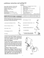
Save This Manual
For Future Reference
owners
manual
MODEL NO=
720.25251
OUTE
CAUTION:
READ ALL
INSTRUCTIONS
CAREFULLY
° assembly
° operating
Sold by SEARS,
ROEBUCK
AND CO., CHICAGO,
IL 60684 U.S.A.
Printed in U.S.A.
generaU safety instructions for router crafter
WRARNING:FAILURE
TO HEED
ALL SAFETY
AND
OPERATING INSTRUCTIONS AND WARNINGS REGARDING USE OF THIS
ODUCT CAN RESULT
IN SERIOUS
BODILY
INJURY_
1. USE SAFETY GOGGLES (Head Protection)
Wear Safety goggles (must comply with ANS Z87.t) at all times Also, use face or dust mask if cutting
dusty, and ear protectors
(plugs or muffs) during extended periods of operation
2. DON'T
is
FORCE TOOL
The Router' Crafter
was designed
for smooth
operation,
3. KEEP HAND CLEAR OF BITS AND WORKING
4. KEEP ROUTER
After
operation
CRAFTER AND ROUTER
therefore,
parts should
never be forced
to operate.
AREA°
CLEAN.
every use clean saw dust off the Router Crafter and Router
NOTE: Motors used on wood-working
tools are particularly susceptible to the acumu]ation of sawdust and wood chips
and should be blown out or "vacuumed"
frequently to prevent interference with normal motor ventilation
general safety instructions for power tools
1. KNOW YOUR POWER TOOL
Read the owner's manual carefully Learn its application and limitations as well as the specific potential
hazards peculiar' to this tool
2o GROUND
ALL TOOLS
(UNLESS
DOUBLE
INSULATED)
If tool is equipped with an approved 3-conductor
cord
and a 3-prong grounding type plug, it should be plugged
into a three hole electrical receptacle. If adapter' is used
to accommodate
a two-prong receptacle, the adapter
wire must be attached to known ground, (usually the
screw securing receptacle cover plate) Never remove
third prong Never connect green ground wire to a
terminal
3. KEEP GUARDS
IN PLACE
in working
order,
and in proper
afignment..
adjustment
arid
4. REMOVE
ADJUSTING
KEYS
AND WRENCHES
Form habit of checking
to see that keys and adjusting wrenches
are removed from tool before turning
it on.
5. KEEP WORK AREA CLEAN
Cluttered
areas and benches invite accidents,
must not be slippery due to wax or sawdust..
Floor
6. AVOID DANGEROUS
ENVIRONMENT
Don't use power tools in damp or wet locations or
expose them to rain, Keep work area well lighted
Provide adequate surrounding
work space.
7o KEEP CHILDREN
All visitors should
area
AWAY
be kept a safe distance
8. MAKE WORKSHOP
KID-PROOF
--with
padlocks,
master switches,
starter keys
from work
15. MAINTAIN
TOOLS
WITH CARE
Keep tools
sharp and clean for best and safest
performance.
Follow instructions for lubricating
and
changing accessories
16. DISCONNECT
TOOLS
before servicing; when changing
blades, bits, cutters, etc
accessories
17. AVOID ACCIDENTAL
STARTING
Make sure switch is in "OFF" position
ging in
such
before
as
plug-
18. USE RECOMMENDED
ACCESSORIES
Consult
the owner's manual for recommended
ac_
cessories
Follow the instructions
that accompany
the accessories.
The use of improper
accessories
may cause hazards
19. NEVER
STAND ON TOOL
Serious injury could occur if the tool is tipped
the cutting tool is accidentally contacted.
or if
Do not store materials above or near the tool such
that it is necessary to stand on the tool to reach
them
20. CHECK
or
by removing
9, DON'T FORCE TOOL
It will do the job better and safer at the rate for which
it was designed
10. USE RIGHT
TOOL
Don't force tool or attachment
designed for
12. USE SAFETY
GOGGLES
(Head Protection)
Wear Safety goggles (must comply with ANS Z87,1)
at all times. Also, use face or dust mask if cutting
operation
is dusty, and ear protectors
(plugs
or
muffs) during extended periods of operation
13, SECURE
WORK
Use clamps or a vise to hold work when practical
It's safer than using your hand, frees both hands to
operate too!
14, DON'T OVERREACH
Keep proper' footing and bala0ce at all times
to do a job it was not
11. WEAR RIGHT APPAREL
Do not w_ar loose clothing,
gloves, neckties
or
jewelry (rings, wrist watches) to get caught in moving parts
Nonslip
footwear
is recommended
Wear
protective
hair covering
to contain
long hair Roll
long sJeeves above the elbow
DAMAGED
PARTS
Before further use of the toot, a guard or other part
that is damaged should be carefully
checked to ensure that it will operate properly
and perform
its
intended
function.
Check for alignment
of moving
parts, binding
of moving
parts, breakage
of parts,
mounting,
and any other conditions
that may affect
its operation. A guard or other part that is damaged
should be properly repaired or replaced
21. DIRECTION
OF FEED
Feed work into a blade or cutter against the direction of rotation of the blade or cutter only
22. NEVER LEAVE TOOL RUNNING
UNATTENDED
Turn power off Don't leave tool until it comes to a
complete stop.
preliminary
instructions
and pack ng
tist
CONTENTS
General Safety Instructions
for Router Crafter
......
Genera_ Safety Instructions
for Power Toots
........
Preliminary
Instructions
and Packing List ,.
Assembly of Name Plate
.............
Assembly of Template
Follower
,
Introduction
....................
2
2
3
3
3
4
Construction
4
.............
Before Setting Up a Work Piece ...............
Mounting the Router on the Router Carriage
......
Wood Preparation
............................
Mounting the Wood Piece in the Router Crafter
.....
5
5
6
6
READING TIME FOR THIS MANUAL IS APPROXIMATELY
MANUAL MAY SAVE YOU HOURS OF FRUSTRATION.
Rounding
up--Turning
from
Circular
Beads and Coves
Roping
(Spiraling)
Straight
Beads
Contour
Turning
Template
Taper
Parts
Chart
.............
(1) Hex Key 5/32
(2) Socket
1/2"
16
..,
Inserted
!/4_20
OD,
Hd. Screws 10-24 x 1 1/2
(3) Pan HaloScrews #10-32 x 1/2
5/8"
O,D.
(_
(4) Clamps
(1) Crank Handle
(1) Template
(Key NOo'SFollower
28, 38, 39
Assembly
and 40)
tn order to help prevent breakage
in shipping,
the
name plate, which shows the model number, and the
template
follower
assembly, were not preassembled
at the factory. Installation
of these parts are quite
simple and instructions for this are provided.
NAME
PLATE ASSEMBLY
The name plate No. 53 (Fig, 20 located at the end of
manual)
has four nose like projections
on the side
opposite the silver lettering.
Hold the name plate in
your hand and pu½h the projection
into the four steel
tubes until the back side is against the tubes, (When
wbrking on wood parts which are maximum length, it
may be necessary
to temporarily
remove the name
plate)..
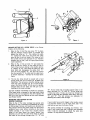
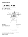
ASSEMBLING TEMPLATE FOLLOWER
Refer to Fig,. 1. Remove the hex nut ('A') from the
template follower assembly° A pocket has been provided in the router carriage for the hex nut. Holding
the hex nut in the pocket, slip the remaining template
follower assembly ('B', 'C' & 'D') over the nose of the
router carriage ('E'). Turn the cap screw until it is
finger tighL Use the hex key which is provided to
tighten the screw. DO NOT OVER TIGHTEN
_I_
_
x 1
(4) Hex Nuts 1/4-20
(7) Flat Washers
in Back
Cover
SPENT READING THIS
(2) Hex Nut 10-24
(4) Sq,. Hd. Screws
15
.........
AND 30 MINUTES
(2) Flat Washer
wrench)
12
14
Drawing
of Full Size Turning
There is a plastic bag which contains some parts that
you must use,. Please check the contents in the bag
with the list to be sure all parts are there,.
(Hexagon
.............
.................
Shooting
30 MINUTES,
10
12
and Construction
List and Schematic
7
8
9
........
................
Layout
Examples
........
..........................
and Flutes Cut Lengthwise
Turning
Trouble
Square to Round
..................
C
D
Figure 1
INTRODUCTION
Your Craftsman
Router Crafter is a newly developed
machine which wilt enable you to utilize your router
to its fullest--making
table legs, turnings,
posts,
spindles
and other turned
carvings
of almost
any
design
you wish. There are four basic operations
which carl be done on your Router Crafter. They are:
A crank (#1) which fits into the back of the drive
spindle is provided to rotate the work piece, You may
notice that the drive spindle (#18) has considerable
"play" or looseness in the cable drum (#20),_ This is
normal and is no cause for concern_
1.
The tail stock (#47) is also an aluminum casting which
carries the tail stock center screw (#50) which is a
1/2" threaded
steel rod° The center screw passes
through a guide bushing (#49) which is adjustable
up
and down to permit turning straight or tapered work
pieces,. The tail stock can be positioned
anywhere
along the steel tubes to accommodate
different lengths
of work pieces,.
2.
Straight "beads and flutes" cut lengthwise
(parallef to the work piece). These may be of a straight
or tapered style.
"Roping"
or "Spiraling" _ both
right
and left
hand -- and may be either straight or tapered.
3.
Turn "beads, coves and steps" around the work
piece. The different forms are made by the shape
of the router bit which is used°
4.
Contour turning
of varied shapes by letting the
router follow a template which is attached to the
front of the Router' Crafter..
The four basic type
hundreds
of different
combination.
The vinyl coated steel cable (#42) which is wound
around the cable drum runs over Deirin® pulleys (#12
& 15) and is joined together with a tension spring
(#41) which serves to keep the cable taut. There are
two metal lugs which are attached to the cableone
on the upper and one on the lower cable lines° The
lugs are for affixing the cable to the cable clamp (#29)
to advance the router and router carriage when making
"roping"
or "spi;aling"
cuts. Attaching the upper cable
lug to the cable clamp produces
a left hand spiral
whereas attaching
the lower lug to the cable clam'p
produces
a right hand spiral. The lugs are left unattached when making other than spiral cuts..
cuts enable
you to produce
designs
by using them
in
Included with this manual are drawings of typical full
size turnings.
(Inserted
in back cover)
When reading any of the sections on the various types of turning,
check the sample being referred to as this wilt help to
understand
the many turning
methods
and designs
which are possible with the Router Crafter..
CONSTRUCTION
Baslca_ty the Router Crafter is composed
of a Head
Stock and a Tail Stock (Fig. 20) which are held in line
with each other by four heavy steel tubes (Nor 44 &
52). A carriage
(#33) which carries
the router
is
mounted to and travels along these tubes_
The carriage
(#33) has two identical
screws (#36).
These are used to adjust the depth of cut and also to
provide a repeatable "stop" or maximum depth gage_.
There are two hose type clamps on the top tube (#14)
which serve as stops for the carriage at each end of
the desired
cutting
travel. The two clamps can be
positioned against each side of the carriage to prevent
any lengthwise
movement of the carriage.
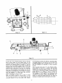
Clamps, screws, nuts and washers 'A' are provided _or
mounting
the Router Crafter on a base or bench. See
Fig, 2, The mounting box 'B' could be made from 1/2
to 3/4 inch wood (plywood
works weII)_ Mounting
Router Crafter as shown gives a place to store toofs,
bits, etc.
The head stock consists
of a cast aluminum
frame
(#6), a cable drum (#20), on which the steel cable
(#42) is wound and which turns inside the head stock
frame, a cast aluminum drive spindle (#18) which turns
inside the cable drum, a locking plate (#9) which will
lock the cable drum relative to the frame, and an index
pin (#!7) which permits the indexing
of the drive
spindle (#18) relative to the cable drum (#20)° The
drive spindle can be indexed in-increments
of 15 °that is the indexing
provides for equal spacing of 2,
3, 4, 6, 8, 12, and 24 cuts around of a work piece.
B
Figure 2
4
C
B
D
ARROW
C
Figure 4
Figure 3
..................................................
::
::::::::::::::::::::::::::::
"' L
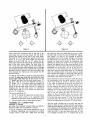
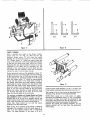
BEFOR'E SE'i_TINGUP
A WORK PIECE in the Router .....
Crafter, do the following:
1o
Refer to Fig. 3. Hold the cap screw "B" in place
with the hexagon wrench which is provided
and
tighten the wing nut "A".. This clamps the plate
"C" against the cable drum and locks the cable
drum so that it can not rotate. (The wing nut wilt
feel a little hard to turn becauseitis
a vibration
resistant nut so that _it will not come.loose
during.
router operation)..'
.........
" ._"
2,,
R_fer'to Fig: 4,: Pull= out knob "A" and rotate the
knob so that the '_wings" on the indeX'pin just in
front 5_ the knob are resting in the shallow groove
or "detent_'at
"B',. This holds the index pin and
knob back and disengages
the .cable drum "C"
from the drive spindle "D", and thus will permit
the drive spindle "D":to rotateand
the cable drum
to remain stationary _ clamped to the..head
stock
=
frame.
3.
The top two tubes should be waxed with a hard
drying paste wax such as Sears No 28 6953 Auto
Paste Wax. This wilt give a smoother sliding action
when the router carriage (Fig., 5) is moved lengthwise in the Router Crafter. Do not use oil or grease,
because they are,too tacky and will _gum up the
bearings in the router carriage.
DONOT !!FORCE" ANYTHING TO TURN° For example;
if the cable drum is clamped to the head stock frame
and the index pin is engaged to the drive spindle, DO
NOT try to turn the drive spindle as this would damage
your Router Crafter°
L
LUG
•
Figure 5
.=
! ....
' "M'II'
'
r,,_,, •
i
"E". If your router has 4 equally spaced holes in the
base, use slots ,A", "O" and "D",' If your Touter has
4 holes but only 2 holes are lined Up.through
ttle
center of the base and opposite each other, use slots
"A" and "C"_ The two .screws
are adequate for
attaching the router to the carriage.
_
_ : •
=
r
ON THE .....
_
r
J
r
MOUNTING TH:E ROUTER
ROUTER CARRIAGE
UPPER
Refer to Fig.5. The router carriage has several slots
through it for use in mounting and attachingthe,
router
to the carriage. Screws and washers are provided for
this purpose. Remove the plastic plate from the bottom
surface.of
your router before mounting _to the Router
Crafter.carriage.
If your router has 3 equally spaced
holes, in the base
where the plastic
platten
was
attached, you will use the same three holes to attach
the router to the carriage through slots "A', "B" and
If your router has a switch trigger in the hand_e, mount
it so that the switch is on the head stock.side _ the
right side as you face the Router Crafter
The screws provided foi mout_ting are #10-32 x 1/2"..
longo If your router base has a different .size threaded
hole, it will be necessary
to obtain the same size
screws 1/2" long from a hardware st0re ....
CENTER
HOLE
Figure 6
WOOD PREPARATION
Sometimes it is difficult to obtain thick wood for
making table legs, posts and so forth, but this isn't
necessary. If you have thin boards such as 3/4" or 1rt
that are smooth, you can put 2, 3, or4 thickness together at one time using Craftsman white glue and
ordinary "C" clamps_ Rip the boards to about 1/4"
wider than you plan to have final thicknes of the
square post..This allows er!ough extra stock to trim the
edges square and smooth after the boards have been
glued together_
The wood piece, of course, should be squared and cut
to length° No further preparation is needed on the end
that is to go into the head stock° The tail stock end
must be center drilled; that is, a small chamfered hole
must be put in the center of the end to receive the tail
stock center. You may use a standard center' drill. If
a center drill is not available, drill a 1/16" or 3/32"
hole about 1/4" deep and then counter sink the hole
to about 1/4" diameter_ See Fig. 6. The center hole
should be lubricated with wax, petroleum jelly, or
some other grease lubricant° DO NOT GREASE ANY
OTHER AREA.
MOUNTING THE WORK PIECE IN THE
ROUTER CRAFTER
The center' bushing "B" should be set at the lowest
graduation mark "C" on the tail stock "D" (Fig. 19).
The tail stock frame can be positioned anywhere along
the tubes as desired _ close to the head stock for
short work, far away from the head stock for longer
work. Generally, if routing is to be done all the way to
the tail stock end of the work piece, the pointed end
of the tail stock center should extend past the tail
stock frame about 3 3/4"_ See Fig° 7. Loosen the 4
screws ("D") with the hexagon wrench which is provided. Place the plain square end of the work piece
in to the drive spindle with the corners of the work
between ribs as shown in Fig, 8_ The end of the work
Figure 7
RIBS
;ENTER HOLE
G
Figure 8
piece with the center drilled (chamfered) hole should
point toward the tail stock. While holding
the work
piece in the drive spindle,
position
the tail stock
frame so that it is about 3 3/4" from the end of the
work piece. Remove the work piece_ Using a tri-square,
combination
square, or triangle (30°-60 _ or 45°), square
the tail stock with the steel bars as shown in Fig 7.
Holding the square in position, tighten the four screws
"D" just snugly, tightening
the top two screws first,
DO NOT OVER-TIGHTEN.
NOTE: THE TAiL STOCK
SHOULD BE SQUARED EVERY TIME iT IS MOVED
(This does not apply when only the center screw is
adjusted).
While
holding
the work
piece
against
the drive spindle, and with the small hexagon nut "B"
seated flat against the tail stock frame, turn the knurled
end of the tail stock center "A" until the pointed
Figure 9
Figure
center enters the chamfered
hole in the end of the
work piece and you can just barely feel the center
touching the bottom of the hole in the work piece°
The small nut "B" should still be against the tail stock
framer (If it is not, you have turned the tail stock
center in too far). With the nut "B" against the tail
stock frame and the tail stock center just touching the
end of the work piece, tighten
the large wing nut
("C") firmly with your fingers. Do not over tighten as
it is not necessary and could possibly bend or damage
the tail stock assembly
This procedure has locked the
tail stock center in position with the work piece held
firmly between the head stock drive spindle and the
tail stock center
You should now be able to rotate the work piece freely
by hand. If, when you rotate the work piece by hand,
it feels tight rather than free 1o turn, loosen the nut
"C" slightly and back the tail stock center screw "A"
out about 1/8th of a turn and retighten the wing nut
"C" snugly. Fig. 7 If, however, after you snugged up
the wing nut "C", the work piece feels loose and
sloppy on the tail stock center, the nut "C" should be
loosened
and the tail stock screw
"A" should
be
turned about 1/8th of a turn toward the work piece
and nut "C" retightenedo
The correct conditions
1
Nut "B" is resting
are:
fiat against
the tail stock frame.
2.
The work piece seems to be supported
firmly
between the tail stock center and the head stock.
3o
The work piece is free to rotate easily by hand°
"ROUNDING
UP" _ TURNING FROM
SQUARE TO ROUND
BE SURE THE ROUTER POWER CORD IS DISCONNECTED FROM THE ELECTRICAL
OUTLET°
To do the rounding of the portion desired, the use of
a Craftsman
Rabbetting
and Surfacing
Bit number
9 26310, which is used with _g2589 Arbor and Pilot
10
Set, must be used. The arbor and bit only are used°
DO NOT USE A PILOT IN THE CUTTER BIT. Adjustable "stops .... H" (Fig. 5), are provided
to limit the
permissible
travel of the router carriage
both toward
the head stock and toward the tail stock
The stop
nearest
the head stock
shouid
be positioned
and
tightened
to prevent the router bit from being moved
beyond the desired end of the round portion of the
work piece° The stop nearest the tait stock should be
positioned
out of the way--as
far to the left as it
can be set--if
the work piece is to be round all the
way to the left end of the work piece. (if it is desired
that only a middle portion of the work piece be round
and a portion left square on both ends, then the left
stop should
be positioned
accordingly
to limit the
movement of the router bit to the left)
Before starting the actual cutting, the cabfe (K) should
be disconnected
from the cable clamp (N) and the
cable drum should be turned so that the spring (L)
in the cable is positioned
as near the tail stock as it
will go. Fig. 5 (This is only to get the spring out of
the way because the cable is not used in the "rounding-up" operation)
The cabte drum shouid then be
clamped to the head stock frame by tightening
the
w_ng nut "A" in Fig 3 Putl the index pin knob "A"
(Fig 4) out and rotate the knob 1/4 turn so it will
remain in the out position
when you let go. Now
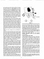
position the bottom of the router bit as shown in Fig
9 Set the feed clown screws "F" (Fig 9) so that they
just barely touch the front bar and lock the screws in
position by tightening the wing nuts "G" (Fig 9) firmly
With the router carriage
off to the left, near the tail
stock (or lifted up out of contact with the work piece),
rotate the drive spindle 1/8 of a turn as in Fig 10 (this
is 3 numbers on the graduated drive spindle) and then
pull back slightly on the index pin knob "A" (Fig. 4),
rotate the knob 1/4 turn and push knob back in_ This
is to engage the index pin in a locating hole in the
drivespindleandprevent,
rotationof_.the
drivespindie.
The knobShouldgo [n Unti[i_"itii!!t_ches or .almost
touches the _,able drum. Make:i_i:eii"_he
index pin is
in eli the way. Yo'U _i_ow may {feel,i:.a;;iittle play or" wiggle
in the_work, piece',but
it sho_jd:'h_{
be free to rotate.
J ggle.t_6..iwo_;k"piece
back and:÷ifofth sffghtly by hand
to be sure th6_w0rk j3iece wilt not rotate before doing
any cutting
I'f your work piece is 2 1/2!' square or
larger, do not try to cut aft the corner
off, the work
piece_ Instead, loosen the wingnut
on the_ right hand
feed screw and screw the pad down about 1/8" to
3/16" and :..re-tighten the Iock'nuL
DO NOT CHANGE
the left _an:d feed screw. This has served'td..raise
the
router bit so that it will m_.ke a lighter cuL
Now plug' the power cord !nto the electrical
outlet
and holding both handles of the router, with the right
hand feed screw resting on the front bar, make the
first cut from left to right (from the tail stock end
toward the head'stock ) until the router carriage contacts the stop nearest the head stock end which was
preset earlier. Turn the router off, raise it slightly off
the bar and return it to the left end of the work piece.
Now you are ready to index to the next cutting position.
Pull out the index knob and turn the drive, spindle
6
numbers (90 °) and. push the pin bac k !n to keep the
work piece from being°free
to rotate_ Lightly twist the
work piece back and forth to be sure it wOfl't' rotate,
and make the second cut just as the first cut was
made,
Repeat the
corners.
same
procedu.re
for
the. remaining ` two
After all four corners have beencut
off, reset the right
feed down screw to/the same position as the left feed
down screw:Rotate
the work piece 3 numbers (1/8
turn). Now make a cutjust
as you did before, from
left to. right: After this first cut, pull out the index
pin again and rotate the_drive
spindte-one
number
counter clockwise ,and push the indeX, pin back in as
before. For example; if an arrow on the cable drum-is:
pointing to number 5 on .the _drive spindle, advan'ce
number 6 to the arrow_if
the arrow is pointing to
number 15, ad'Jadce number 16 to.the ai'rSw.,.
After advancing,
or rotating,
the work
piece one
number, and you have checked .to be sure the index
pin is "in" and the work piece is not free to rotate,
make another cut,from
left to right as before. Repeat
this procedure until you have cut all the way around the
work piece -.checking
each time to .be sure the index
pin is in the proper position.and
the work piece; is not
free to rotate.
:
After going all the Way around the vvoH;{ piece, the
work piece will shOW a series of 24 small "flats _'
around the piece. To'remove these l_roceed as followso
Pull the index:pin out, rotate it 1/4 turn and release it.
This disengages
the index pin-_r0rn-the
drive Spindle
and the drive spindle is free to rotate_ With the router
carriage to the left of the work piece, loosen the Wing
nuts on the feed down: scre_vs.and
raise the screws ,
just slightly/:_about
a half turn each and lock them
in position by retightening
the wing nuts/_ ....-_":
'_
With. the hand Crank in ttle drive sp_indt_' and. tt_e
router on, (otate the work"_iece.
With. tf_e c[aqk in a
counter' clockwisedirection'
as y0u look atthe
head
stock end of the Router Crafter. (The top surface of
the work piece, is turn!ng t(_wards you.) While rotating
the work piece with the 'fight hand rather: rapidly,
gradually pull the rot_ter towards the head stock until
the €'arriage contacts the stop which wasset
earlier.
Thiscompletesthe
rounding of the Work piece.
iyou wish, wrap one turn of adhesivetape
around tl_e
square end of the hand crank and .lightly wedge the
hand ciank into the drive Spindle...This
will keep tl_e
hand crank tight in the drive spindle,
UNPLUG
THE
POWER CORD. TO THE ROUTER
BEFORE
CHANGING
CUTTER
BITS
OR MAKING
ADJUSTMENTS
._
CIRCULAR :BEADS AND COVES
:
...........
Circular
beads and coves, as we refer" to thehi herel
are those which are formed 13y the shape of the cuttei
bits used and/or
a combination
of different
bits. In
cutting
these,' _the rotfter
does not move along the
steel bars of'the
Router Crafter
The {wo Stops are
positioned against
the rOOter carriage =--one a_t'each
side _ to prevent such movement. The cable:drum
is
c[amped just as it is during the "rounding-up,
opera=
tion..r,The index pin is out, thus disengaging
the drive
spindle from the cable drum and the drive .spindle is
free to rotate.
Refer to Fig 11. With the desired bit _'A" in the r:outer,
adjust the feed down screws "B!' until the bit makes
contact
with the work piece. Continue
to raise, the
feedS'screws until the distance between steel bar "C"
and the feed down screw is aplbroximately
two times
that of the desired cut depth "X".
'
Connect the powei" c01"d to the _elec:tric&l :outiet. With
the router running, turn the' :work piece with :the crank
and gradually
lower the router inte._he work piece
until the feed down screws contact the front steel bar:
Lift."the ' rou'ter ;out .of the .'Cut before turning
the
router off..
DIscONNECi_THEPOWER
_oRD }='ROM THE ELECT.R!CAL OUTLET BEFORE. CHANGING CUTTER B!TS
OR MAKING ADJUSTMENTS.
ROUTER
BIT NO.
*These bits
Could be
used for
this cut
*26316
26315
26314
26312
Figure
You can make circular cuts in this r=tanner with any of
the cutter bits which will "plunge" or "end" cut.
If you wish, you can position the router carriage to the
right or left to make another cut to blend in with the
previous cut.,
ALWAYS BE SURE THE STOPS HAvE BEEN POSITIONED
AGAINST
EACH SIDE OF THE ROUTER
CARRIAGE AND TIGHTENED
BEFORE ATTEMPTING
TO MAKE CIRCULAR
CUTS. FAILURE TO DO SO
COULD CAUSE YOU TO RUIN THE WORK PIECE° See
Fig 12 for typical beads, coves, and flats made on
the Router Crafter_
Fig. 21 through 31 show futl size drawings of various
style parts with coves, beads, etc, (These are on a
separate sheet and inside back cover)_
Sand the work piece with coarse sandpaper
then
progressively
with finer grit paper. You may turn the
work piece with the crank for initial sanding
This
applies to all the various types of turning covered in
this manual.
ROPING
(SPIRALING)
Among the many types of cutting which can be done
on .your Router Crafter
is "roping"
or "spiraling",
which
is. rather
unique.. Roping
is the cutting
of
spiraled
beads around the work piece, so that the
piece looks somewhat
like a rope° Spiraling
is a
general term and refers to any form or shape of spirals
around the work piece. You can cut right hand and
_eft hand spirals _both
on the same work piece if
you wish to produce a "pineapple"
or diamond effect.
The drive spindle has 24 positions marked on it and
by means of the index pin, can be set to 24 equally
spaced positions; therefore, you can make your choice
of 2, 3, 4, 6, 8, 12, or 24 equalfy spaced spirals
The portion of a piece which is to be roped or spiraled
should, of course, be rounded up prior to the spiraling,
and, in order to achieve best resu/ts, the work piece
should not be removed from the Router Crafter after
12
rounding
done.
up
until
the
roping
or spiraling
has
been
For roping spirals either a craftsman
No. 9_26324
(3/16" quarter round) or a 9. 26323 (9/32" point cutting
Ogee) bit should be used. Put the cutter bit in the
router and set the feed down screws so that the bit
will cut about 1/8" deep in the portion bf the work
piece which is to be cuL When the cutter bit _s _n
Cutting position,
the axis of the bit should
point
directly to the center of the work piece (Fig,, 11)o NOw
set the carriage stops which are on the rear bar in a
position which will only permit the carriage to move
as far to the right and to the left as you want it to,.
This serves to prevent accidental
over travel and the
cutter hitting some other part of the work piece. It is
preferred
that the carriage
movement
to the left
(toward the tail stock) be far enough to get the cutter
past the left stop° This is preferred because the actual
cutting of all spirals and ropes is done with the router
moving from the tail stock end toward the head stock
end _eft to right)_ NEVER SPIRAL CUT FROM R_GHT
TO LEFT--_ doing so would produce an inconsistent
cut.
At this point, be sure that the cabie drum is not
clamped to the head stock frame., if it is, unctamp it by
loosening the wing nut "A" (Fig 3),
The cable clamp "N" (Fig,. 5) must now be attached to
a steel "fug" which is permanently
attached to the
cable. There is one lug on the top cable and one lug
on the bottom cabfeo Attaching
the cable clamp to the
lug on the top cable will produce a left hand spiral,,
Attaching
the cable lamp to the lug on the bottom
cable will produce
a right hand spiral
There is a
recess or "pocket"
in the cable clamp under the flat
washer in which the lug will fit,. Place the lug in the
recess of the cable clamp, and with the lug under the
flat washer, tighten the cap screw with the hexagon
wrench until the washer clamps the tug to hold the
lug in the recess, DO NOT OVER TIGHTEN _ JUST
TIGHT ENOUGH TO KEEP THE LUG FROM MOVING.
Now,withtherouterliftedupslightlysothatthecutter
bit doesnot touchthe workpiece,rotatethe crankin
the directionthat pulls the router'towardthe head
stockuntilthe carriagecontactsthe stopnearestthe
headstockend.Checkto be surethatthe cutteris
nowat the pointat whichyouwantthe movement
of
the cutterto stop.Withthe routerstill liftedupslightly
off the work piece,reversethe crankdirectionand
returntheroutercarriagetothetailstockend.
Nowlet the routercarriagefeedscrewpadsrest on
when the cutting depth is correct, the center Iine of
the cutter bit is pointed to the center of the work piece.
The depth of cut is set by positioning the down feed
screws "F" (Fig. 5). After positioning the down feed
screws, be sure to lock them in place by tightening the
wing nuts "G" (Fig,. 5). Of course, the router can be
adjusted up and down in its own base as is customary
with routers,
The carriage travel stops "H" (Fig. 5) should be set so
that the carriage,
and thus the cutter bit, can only
move lengthwise
in the area that is to be cut. This
serves to make consistent
length
of cuts and to
prevent accidentally
moving the router carriage too far
and cutting into a portion of the work piece you don't
want cuL Turn the cable drum until the spring in the
cable is at the extreme left toward the tail stock as far
as it will go,.
the front bar and turn the router on. Hold the router
handle with the left hand, and with the right hand,
turn the crank fairly slowly, but steadily, to pull the
router along the work piece toward the head stock. DO
NOT STOP
TURNING
THE CRANK
WHILE
THE
CUTTER BIT IS IN CONTACT WiTH THE WORK PIECE.
If for some reason you do not want to complete the
cut, lift the router up off the work piece and return the
router to the tail stock end.. Do not crank backward
with the cutter bit in contact with the work piece.. To
do so would cause an inconsistent
spiral, thus ruining
the work piece°
The cable drum "C" (Fig_ 4) should now be c_amped
to the head stock frame. This is done by holding socket
head screw "B" with the hexagon
wrench provided
and tightening
the wing nut "A" (Fig_ 3),. The wing nut
will feel a little hard to turn because it is a vibration
resistant
type wing nut.. Do not over tighten _ just
enough that you can't turn the cable drum by hand_
The index pin "A" (Fig. 4) should be "in" , that is, the
knob should be touching, or very near to touching, the
back side of the cable drum. This Eocks the cable
drum to the drive spindle so that the drive spindle
will not rotate.
After the first cut has been made, and the router has
been turned off and returned to the left end of the
work piece, notice what number the arrow on the
cable drum is pointing to (Fig 4)_ If you want eight
equal spaces around the work piece, pull the index
pin out and turn the drive spindle
three numbers
(either direction)
and push the index pin back in. This
has turned the work piece 1/8 of a turn and you are
now ready to make another spiral cut. if the original
depth of cut was not quite deep enough, you may
drop the cutter bit slightly by loosening the wing nuts
of the feed down screws, backing the feed screws off
slightly and retightening
the wing nuts_
The first cut should be made with both hands on the
router feeding from left to right at a reasonably steady
spee& Do not stop in the middle of a cuL tf for some
reason it is necessary to stop, raise the router up so
that the cutter bit is not in contact with the work piece
before stopping
the feed of the carriage,
When the
carriage has been moved all the way to the "stop" at
the head stock, or right end, lift the router up slightly
off the work piece, return the router to the left end
stop and turn off the router_
Make the second and remaining
cuts in the same
manner as the first cut° The index positions
are
numbered 1 through 24; therefore, for example, if you
want to make 8 equal spirals and the first cut was
made with the arrow pointing to number one, then the
other cuts should be made with the same arrow pointing to numbers, 4, 7, 10, 13, 16, 19 and 22° It is a good
practice to write down the number you start on and
nil the other numbers you must index the arrow to for
the correct number of equal spaces so that you don't
have to remember
the original
number you started
on--helps
to prevent mistakes
that could ruin the
work piece_
Figs. 21, 22, 25, 26, 30 and 31 are examples
and spirals..
Now the work piece should be indexed to the position
to make the second cut. Be sure that the cutter bit is
not touching the work piece If, for example, you want
twelve equally spaced cuts, pull the index pin back
and rotate the drive spindle
two number-s and push
the index pin back in_ It is important
that you note
what number is next to an arrow head on the cable
drum. It is best to write down the number and then
write down all the numbers you must locate at the
arrow head to make the remaining cuts. If the first cut
was made at number 24 position, for example, to get
the twelve equal spaces, you would also cut at positions 2, 4, 6, 8, 10, 12, 14, 16, 18, 20 and 22.
of ropes
DISCONNECT
THE POWER CORD FROM THE ELECTRICAL OUTLET BEFORE CHANGING CUTTER BITS
OR MAKING ADJUSTMENTS.
STRAIGHT
BEADS
AND FLUTES
ALWAYS REFER "TO THE SAME ARROW THAT WAS
REFERRED TO WHEN MAKING
THE FIRST CUT.
(Fig. 4) ALWAYS BE SURE THE POWER CORD IS
DISCONNECTED
BEFORE
MAKING
ADJUSTMENTS
AND CHANGING CUTTERS, ETC.
CUT LENGTHWISE
Cutting the straight, lengthwise,
equally spaced beads
and flutes can be done very quickly.
DISCONNECT
THE ROUTER POWER CORD FROM THE ELECTRICAL
OUTLET., Select the proper cutter bit for the shape of
cut you desire to make and install in the router coIlet.
The router is positioned on the router carriage so that
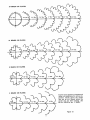
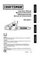
Fig. 23, 24 and 25 are examples of flutes cut lengthwise. Fig !3 shows shape of lengthwise beads of various size work pieces with different
numbers of equal
spaces.
10
24 BEADS OR FLUTES
6 BEADS OR FLUTES
Typical cross sections of beads and
flutes cut lengthwise for various diameters_ Beads above the center
line are as cut, Beads below the
center line are after sanding. Use
bit No, _926323 or No, 9_26324.
Figure 13
tl
CONTOUR
TURNING
DISCONNECT
UP.
o:::'i
THE
:
':
POWER CORD
router
BEFORE SETTING
:.
1: ; ..... i-. .::
toward
the head stodk slowly.
'
_"' While the:. feed screw pads are resting or] the front
• .... bar, you-_ilf
be' cutting
about i/8"
deep; As you
..move. along; the. template will lift the-router
up as :it
goes over:the
higher portions
of the template• When
you contact.: the stop a_tthe right, lfft the router up out
of contact with the work pie:ce turn:the router of.f and
return the carriage
to the .left,end. "Again; w th the
fee'd down scre_vs_ let the router bit down about
another 1/8", tock the feed down screws by tightening the wing nuts and make another cut just as you
made the first cut Continue
this process
until the
template
follower
contacts
the template
for the full
length of the turned portion. Traverse the router very
slowly while making the last cut and then unpiug the
power cord.
It is::neCe._sdry to make a tempi_te to make _,bi_toure_
turnings. There is a. !/2" diameter, cylinder on the front
of the router carriage
"J" (Fig:" 5) which wiil rest on
the template and thus !aise and .lower the router as it
moves'along
the rear steel bar. Craftsman No. 9 26326
Core Box Bit is used. when c6ntour
turning
(the
diamete_ 6f' the bit is the same as the diameter of the
template fOllower "J" Fig. 5). One end.of tl_e template
is bolted to the head stock frame and the other end is
bolted to the tail stock frame as shown in Fig. 16.
(Instructions
on making templates follow this section).
When contour turning is to be done, the cable drum
should be rotated so that the spring in the cable is
as far toward tSe left erid (tail stock)as
it ,will go, and
Fig, 22, 23, 24, 25, 26, 27, 28, 29 an.d 30 show-examples
then the 'cable:drum
should, be clamped to the head
of contour turning.
stock frame by tighte0ii_g the': wing nut :"A" (Fig. 3).
DO NOT OVER TIGHTEN THE WING NUT --, tighten
TEMPLATE
LAYOUT,AND
CONSTRUCTION
just enough that you .can not rotate the cable drum by
Refer to Fig_ i4L"]'he
carriage
"A" piv.ots about, steel
hand. The index pin should be pulled back and.turned
1/4 turn so that the drive spindle is disconnected
from ... •bar "B'. With the center_, line of router bit !'C" in .Line
with center of.I he:work piece "D'[, t'he distance from
the cable dr_m and is fre_eto:,rbtate:. _:
'
, -.,-:..
.....................
::,- ................. :'.-...................... :............
'. piyot point..t.iE" to the.centek of brat.
......C.. is.appr_,_imately
..
In this type turning,. the final depth of cu.t"is deter' one half the distance from point ":E" to template "F'I.
mined by the position
of the end of the" router bit
With the fol!ower "G" onthe tempi&tO, any up or doWh
relative to the template follower_ For the purpose of
movement
of the follo_er,_ as it moves .aiong..:_the
explanation,
assume' . there is a work piece:in
the
:template, will cai]se the router bit to mov.e up dr' down
Router' Crafter which you have a!ready rounded
,up_
approximately
orle. tialf the a#lount that the follower
Now, With the template
follower
"J" (Fig. 5) resting
• moves t)p or down, For example, if a work piece is to
on the highest.portion
of.the' templar e (that is to say,.have a drop of 3/8 inch (3/4 inch diameter reduction),
the router sh_ft is right over the portion';of..the
work
the template would have a drop of 3/4 inch. That is,
piece which is to be the largest diameter after turning),
a change
in the height of the template
produces
set the router so thatthe
bottom end of the-'l_/2" core
approximately
the same change'i_i.:the
diame_er;of"_the
box bit just touches the round surfade of the work
work piece.
piece. Be sure the router' cotlet is adequately tighter_ed
• See Fig, 15,, The first thing to do in making a template
to hold the bit. Now move the ro.uter to the left end so
for contour turning,
is to draw the work iEiece "A"
that the bit is just off the work ldiece and agaih let the
_ (Fig 15), to,full
size about center line "E". Having
template follower rest on the template, If the template
completed
the drawing,"aibide
the. contoured
section
is on properly, the end of the router.bit should be J
irito
'equal
parts;
along
the
le'ngth,'
bY
drawing.'
Vertical
even with the desired finished_:dia'_et_fr"at
the e6d of
the work piece (that is, the e_d:.of"the
'=rbuter bit is ...........
.._:.4inest'B" (1/8 inch or 1./4 inch spacing);-Measure'the
above the tail stock center by:a distance of one half ,
distance from the center tine to po.int "c",, Double this
measurement
and mark. point "D" "on. the vertical line.
the desired finish diameter
at the end af the work i
VVhen all the'_bints
have_b_en marked_draW_ a smooth
piece)_ If the bit is higher than that, the left_nd
of the
fine "F"
through
the points:
This completes
the
template
must be lowered. If the.bit, is too _ tow_ the
template 4ayout'..See
examples 22, 23, 24, 25, 26, 27,
left end of the template must be raisedl
.
_,
28;'29. and 30. The template layout is drawn above the
Again, the actual cutting
must be done from ieff to.
• contoured
section on all the examples with contoured
right while turning the crank counter cl0_kwise as you
portions.
look at the head stock, or "crank"
end of the Router, ........
Long Contoured Turning, Sa,_La! pieceiof
Vgb:dd:i,'_B".
Crafter° The top of the work piece should be coming
(Fig./16
plywood .works well), about 1/2" or 3/4"
toward you as you ._face_the Route'r Grafter and • rotate
the oran'kwith
your,, right,_hand: _ _-_',
..
"
. thick', 5 inches wide, and 10 inches longer than the
N_'w,"set':the =feed ctown"s_rews _o?that the bit can take .'_' full i&ngth of the iwork piece° Glue or tape tt_e t_mp!ate
layout "C:" on the woocl" So that (1). the :teft end is
ab;6ut:l_8_
depth o:fcut"aii_
,!bc_ the,: screws
in _
about 7_inches from the end, (2) the..highest point, on
p'ositidr_'"b_':tigh{eni:hg'iJ:the
•.wing'"nut&
Do not" tr_;Zto "
the layout is e_en With t_ie_top ' _edge of the wood, (;3)
take t'h'e fLilI dept)l of the"f0"r:m '_Su"are to cut 'at "_one .........
:i._':
tl_e c_nt_ Iii_e of the la_y_ut is parall'elt0
tf_e=tb'¢"_dg_: _
time if it is deeper than 1/8"
Set the stops on the :_: Saw along the layoU't line and _file: andl sand_-the
rear bar so that the carriage can only be moved over _
temp ate edge smooth_
.'
;
_
the portion of work piece to be turned
The:template-is.
now ready for mountin'g.
With a
Now with the router on, turn the work p'iece, as
rSunded work piece "D" in 'the Router Crafter, hod
instructed
abo_e aVmoderate
speed and pull tl_e
the temp!ate against"the
head and tail stock so that (1)
12
G
D j7
A
Et
C
_
',,_
B
F
!
B
Figure 15
Figure '14
D
1
G
A
\
F
F
A
Figure 16
1/2 inch piece of wood "B" about
The length should be the same as
net fasten together. Glue a template
saw the template
as instructed
turning,
the left end of the contoured section lines up with the
end of work
piece,
(2) the lowest
point on the
contoured section is at least 3/8 inch above the front
steel bar "E". Spacing blocks or dowels "F" may be
used to keep the template straight while marking the
mounting
hole and slot iocations. Drill a 1/4 inch
diameter hole in the head stock end of the template..
Drill a 1/4 inch diameter by 1 inch slot "G" in the tail
stock end of the template. The template may now be
mounted to the Router Crafter with number 10 screws,
nuts, and washers
"A", which have been provided.
Keep the template for future turnings..
3 1/2 inches wide_
the first piece. Do
layout to "A", and
in long contoured
With a rounded work piece "C" in the Router Grafter,
place pieces "A" and "B" in position.
Saw the side
opposite the contoured
edge of piece "A" until the
lowest point on the contoured edge is at least 3/8 inch
above steel bar "D",, Pieces "A" and "B" should be
either glued or screwed together as shown in Fig° 18.
The template
is now ready to be positioned
and
clamped to the Router Crafter
Motmting
Base "E"o
Piece "A" should be against steel bar "D"o Keep the
template for possible use on other parts in the future.
Short or Repetitive
Turning.
Saw a piece of wood
about 1/2" to 3/4" thick by 7 inches wide, "A" (Fig
17) The length should be 1 to 2 inches longer than the
contoured
section of the work piece. Saw another
13
.q
"_ *-- A
\1
,,_-A
_A
\.!
B
B
(a)
D
i
v/ i/ ssA
(c)
1
E
Figure
TAPER
17
Figure
18
TURNING
With a rounded work piece in the Router Crafter,
loosen wing nut "E" (Fig.. 19)_ With the hex key
provided,
!oosen screw
"A" and move the center
bushing "B" up about two marks "C" on the tail stock
"D"o Tighten screw "A". Adjust the center screw and
wing nut as instructed in the wood preparation
section,
so that the work piece turns freely. With a No._g 26310
Rabbeting Bit, take approximately
1/8 inch cut as was
instructed
in the latter
part of Rounding
Up., The
diameter of the work piece at the tail stock end will
be smaller than the diameter where the bit stopped
cutting We refer to th!s as taper turning.
On the tail stock, there are five graduation
marks "C"
ranging from zero to one inch taper over the full length
of the work piece. Fig. 19. With the top edge of the
center bushing "B" positioned directly over the lowest
mark, the center screw "F" would be approximately
in line with the center of the head stock. Turning at
this setting would have zero taper (straight turnings).
Positioning
the center bushing over the second mark
would raise the center screw approximately
1/8 inch
above the center of the head stock, thus producing
a
taper of 1/4 inch over the length of the work piece.
Moving the center bushing up each additional
mark
will increase the taper by 1/4 inch, up to one inch
taper over the full length of the work piece.
Figure 19
inches and the small diameter is to be 1 1/2 inch The
cross section would look like that shown in (c) Fig. 13o
The turning in Fig. 24 was turned as described
Turnings in Fig. 25 and 31 have tapered sections.
The sections on Roping and Straight Beads and Flutes
Cut Lengthwise apply to tapered turnings° If a rope or
straight flute is to be put on a tapered section, the
center bushing must remain on the setting used for the
taper. If the work piece is to have circular beads or
coves, then these should
be cut with the center
bushing set on tile lowest mark.,
above°
NOTE: When laying
out a work
piece on paper,
remember the graduation
marks "C" Fig> 19 indicates
the amount of taper that would be produced
if the
work piece was turned from the tail stock end to the
head stock end. On all work pieces, the difference
between the largest and smallest
diameter,
for any
tapered
section,
will be less than the graduation
mark setting.
Refer to Fig. 13 for possible cross section of different
diameters.
For example, a 29 inch work piece is to
have a 12 inch tapered section with !2 lengthwise
flutes> The large diameter
of the taper is to be 2
14
25
25
TO
_E
USED
WH_:N
TEMPLATE
TO
HEAO
.STOCK
TAIL
\
,k,'_OUIiTING
STOCK
ARO
26
26
24
TO
54
B_
USeD
ROUTEt_
TO
WHE_
MOUNT|NG
ROUTER
CARRIAGE
32
28
i
j
j_
53
\
\
\
\
14_
24
43
21
22
45
\
10
\
48
49
50
28
51
40
39
28
10
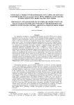
Figure 20
_5_
19
24
21
23
PARTS LIST FOR CRAFTSMAN
MODEL
Y,EY
htO,
1
PART
NUMBEn
DESCRIPTtON
29LDq42
QUAt_
C_'ank Handle
ROUTER
CRAFTER
NO, 720_25251
KEY
NO.
PART
NUMBER
I
29
29LD-133
1
3t
"32
2£LDqSO
29A-249-5
DESCelPTION
QUAN,
Cable Clamp
1
2
3
4
5
29LD-138-2 ...... Lock ,Ring
29A-49t_2
Push Nut
29LD-137
Index Pin Knob
......
1
1
6
*7
29LD-125
29LD-159-1
Head Stock
Set Screw #10-32
8
g
29LD-154
29LD-143
29A-316-4
Wing,Nut
#10-24 (Nyl0,n !,nsert)
Cable Drum Ctamp
Screw #10-24 x 1 112 Socket Hd.---Cap
29A_250-4
Retaining
13
29LD-t30
29LD-t44
One inc h pulley
Double Pulley Shaft
15
16
17
2gLD_129
29LD-t3g
29LD-146
18
19
20
"21
29LD-124
29Ao324-7
29LDq27
29A-306q0
D_'ive Spindl e
Roll Pin 1/8 din. x 5/8
Cabie Drum
Washer 1t4 inch
29LD-140
Conduit
29A-305-I
29A-242-4
Screw Sq, Hd, 1/4-20
Hex Nut 1/4-20
"10
11
12
Ring
...........
' "22
"23
"24
25
29LD-t34
.......
26 29LD-141
• 27 29A-316-5
"28
29A-305-11
Screw
,
"35
29A-309-2
36 29LD-147
37 i 29LD_131
,Screw, Sell Tapping
Adjusting
Screw
Rest Pad
7
4
38
*39
29LD-t55
29A-242-5
P/M Bushing
Hex Nul #10-24
1
40
41
2gA-3!6-3
29A-36
Screw Socket
Spring Ext.
.......
2
.................1....
I
.......
1
1
1
7
length
inch ...... _
4
6
Knob
2
Nyl.ine.r. Bea[!.Eg
2
Screw S£cket Hd, Cap #!0[24 ,x 3/4
Washer #10
This shael is intended
42 2gLD-132
43
44
"45
'46
47
48
49
............
4 .......... 50
x.1 ....................
"Standard
t _-_
1
1
...... .....2
Two ,!r_Ch Pulley
Spring
Index Pin
Ciamp 3/4
Router Carriage
Wing Nut 1/4-20
1
aJu b!;stop
,
,
33 29LD-12B
"34 29LD-252-I0
1
4
x 1/4
Retaining Ring
Hex Key (Wrench)
*5t
52
53
"54
1
2
#tO-24,Type
F
2
2
2
1
B
Hd, Cap #10-24
x 1
2
1
29LD-146
Cabte Assembly
Single Pulley Shaft
!
t
29LD-145
2gA-252-tl
29A-306-12
Pulley Tube
Wing Nut 1/2-t3
Washer I/2
t
1
1
2gLD-t26
2gLD-152
2gLD-153
Tail
Stock
Grooved
1
Pin 3/16
din, x 5/8 Type D
1
2gA-242-6
2_JLD-149
Center Bushing
Center Screw
Hex Nut '_/2-13
Frame Tube
1
1
1
3
37LD-42
Name Plate
t
29A-264-5
S_rewPanH_ i0:32 x i_,'_
29LD-136
J Owners Manual
. 1 ........ 55 . 49LDq
1I
items may be purchased
for instruction
1
1
5/32
locally
Bed repair parts only and is nol a pecking
3
......
slip
1
TROUBLE
SHOOTING
TROUBLE
Burned
places
PROBABLE
on turnings
la)
CHART
CAUSE
SUGGESTED
Moving router too slow
la)
REMEDY
Move router faster
Crank work faster
lb) Work rotating too slow
1c) Bit remaining in place too long
tb)
lc)
ld)
le)
tf)
Router is not running
Pitch or gum on bit
Bit is dull
ld)
le)
lf)
la)
lb)
Cut is too deep
Feeding bit too fast
la)
lb)
Take smaller
Feed slower
Work rotates freely (when not cutting)
but is hard to rotate when cutting,
la)
lb)
Router is not running at full speed
Bit is dull or gummed up
la)
lb)
Have router checked
Sharpen or clean bit
Work piece will not stay snug in the
drive spindle
ta) Tail stock loose on steel tubes
la)
lb)
Tighten
ta)
lb)
Set center bushing on the lowest
setting, See Fig. 19
Square up tail stock
la)
lb)
Feed router slower',.
Reposition
work piece.
Excessive
Splintering
lb)
Work piece
incorrectly
t c) Center
Rounding Up
(1) The cut section
Lengthwise
contoured)
is not straight,
Turning --
(Straight,
(1) Finish cut is excessively
has spiral like cuts,
hole keeps
spindle
enlarging
la)
Center bushing
the head stock
is not in line with
lb)
Tail stock
tubes
ta)
lb)
lc)
Router is traversed too fast,
Work is in drive spindle incorrectly
Router bit is loose in router.
is not squared
with steet
Clean bit with pitch and gum remover
Replace or' sharpen bit
cuts
tail stock, See Fig, 7.
Put work piece in drive spindle such
that the corners are between ribs_
See Fig, &
1c) Readjust center screw and lubricate
center hole of work piece.
taper, or
rough, or
(2) Router bit surges into work piece,
(3) Length
in drive
at full speed
Keep the router or work piece moving
when routering,
Have router checked
of cut was too long,
Beads & Flutes cut lengthwise
(1) Beads or flutes not spaced equally
around work piece,
ld) Work piece is loose on center screw.
2a) Work piece is being rotated
clockwise as the router is moving
from left to right
3a) Adjustable stops incorrectly
positioned
See Fig. &
Ic) Tighten router bit,
ld) Tighten center' screw,
2a) Change the direction
of rotation,
of the crank,
3a) Reposition
adiustable
and tighten
3b) Adjustable
stops loose.
3b) Reposition
stops,
la}
inaccurate
indexing
la)
tb)
Ic)
Cable drum was not clamped,,
Cable drum slipped.
lb)
Clamp cable
lc)
Tighten
la)
Ciamps not tight against
carriage_
la)
Tighten clamps
position,
stops
adjustable
Check indexing of work piece with
numbers written down,
drum,
clamp.
Beads & Coves
(!)
Router bit moves lengthwise into
circular beads or coves.
Spirals
(1) Spirals not equally
work piece,
spaced
around
Contoured Turning,
Finished turning does not look tike
layouL
Taper Turning
(1) Cannot get enough
match layout.
taper
to
1) Inaccurate
router
indexing
with router
in
1) Check indexing of work piece with
number which was written down,
la)
tb)
Template was sawed incorrect
Template was positioned
incorrectly
la)
tb)
la)
Layout
lb)
Taper
I a) Check to see if taper was drawn
for full length of work piece
lb) Reset taper setting. (The
maximum taper is one inch over
the full length of the work piece,)
drawn
incorrectly
setting
is incorrect.
16
Remake or rework tempiate,
Reposition template
owners
manual
DEL NO.
720.25251
WHEN CORRESPONDING
ALWAYS GIVE THE
FOLLOWING INFORMATION
AS SHOWN IN THIS LIST.
1.
2.
3.
4.
11-91
The
The
The
The
Sold by SEARS,
/-
PART NUMBER
PART DESCRIPTION
MODEL NUMBER 720.25251
NAME OF ITEM--ROUTER
CRAFTER
ROEBUCK
AND CO., CHICAGO,
IL 60684 U.S.A.