1
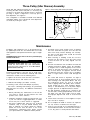
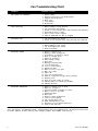
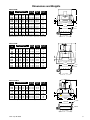
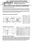
Centrifugal Powered
Roof & Wall Exhausters
IM-4050
August 2014
INSTALLATION, OPERATION & MAINTENANCE MANUAL
Models
DCLH, DCLP, DCRD, DCRU, DCRUR, DCRW, DCRWR
BCLH, BCLP, BCRD, BCRD-E, BCRU, BCRUR, BCRW, BCRWR, BCRUSH
Twin City Fan & Blower Catalogs 4050, 4105 and 4135 provide additional information on this equipment. These catalogs can be found at www.tcf.com or by contacting your local Twin City Fan & Blower sales representative.
Nomenclature
B CR U R - 120
D = Direct Drive
B = Belt Driven
CR = Centrifugal Roof Exhauster
CL = Centrifugal Low Profile
D = Downblast
U = Upblast
W = Wall Exhauster
H = Hooded
P = Penthouse (Louvered)
Fan Size
R = Restaurant
SH = Smoke & Heat
Receiving, Inspection & Unpacking
When the equipment is received all items should be carefully checked against the bill of lading to be sure all crates
and cartons have been received. Before accepting delivery, carefully inspect each carton or crate for visible shipping
damage. If any damage is noticed, the carrier should make the proper notation on the delivery receipt acknowledging
the damage. Make notations of all damage on all copies of the bill of lading and have all copies countersigned by
the delivering carrier. The carrier should also fill out a Carrier Inspection Report. The factory Traffic Department should
then be contacted. File claim for damage with the carrier. Physical damage to the unit after acceptance is not the
responsibility of Twin City Fan Companies, Ltd.
Unpack each carton or crate and verify that all required parts and proper quantities of each item have been received.
Refer to drawings for part descriptions. Report shortages or missing items to your local representative to arrange for
replacement parts.
Due to availability of carriers and truck space, it is not possible to guarantee that all items will be shipped together.
Verification of shipments must be limited to only those items on the bill of lading.
The unit nameplate must be checked to make sure the voltage agrees with the power supply available.
General Installation
CAUTION: Sheet metal parts, screws, clips and similar items inherently have sharp edges, and it is necessary that the
installer and service personnel exercise caution.
The installation of this equipment shall be in accordance with the regulations of authorities having jurisdiction and all
applicable codes.
This equipment is to be installed by an experienced installation company and fully trained personnel.
The mechanical installation of the exhaust ventilator consists of making final connections between the unit and building services, duct connections.
©2014 Twin City Fan Companies, Ltd.
Shipment of Motors
Larger motors will ship loose in order to prevent shipping damage, per the following charts.
BCRU, BCRUR, BCRUSH, BCRW, BCRWR
BCRD, BCRD-E, BCLH, BCLP
SIZE
SHIP MOTOR LOOSE
SIZE
SHIP MOTOR LOOSE
110B – 160B
140HP – 160HP
• 143T and larger – ODP/TE Cast iron frames
• 145T and larger – ODP/TE Rolled frames
• 143T and larger – Explosion-proof motors
• 143T and larger – ODP/TE Cast iron frames
• 145T and larger – ODP/TE Rolled frames
• 143T and larger – Explosion-proof motors
180B – 240B
180HP
• 145T and larger – ODP/TE Cast iron frames
• 182T and larger – ODP/TE Rolled frames
• 145T and larger – Explosion-proof motors
300D – 360D
240HP – 300HP
• 182T and larger – ODP/TE Cast iron frames
• 184T and larger – ODP/TE Rolled frames
• 182T and larger – Explosion-proof motors
300B – 360B
210HP – 300HP
• 182T and larger – ODP/TE Cast iron frames
• 184T and larger – ODP/TE Rolled frames
• 182T and larger – Explosion-proof motors
420D – 480D
360HP, 540
• 184T and larger – ODP/TE Cast iron frames
• 213T and larger – ODP/TE Rolled frames
• 184T and larger – Explosion-proof motors
420B – 480B
360HP
• 184T and larger – ODP/TE Cast iron frames
• 213T and larger – ODP/TE Rolled frames
• 184T and larger – Explosion-proof motors
070D – 160D
100HP – 160HP
• Motor HP larger than shown on TCF&B Price
List P-4105
180D – 240D
180HP – 210HP
Electrical Connection
1. Connect supply wiring to the disconnect switch
(non-fused standard). Check the wiring diagrams on
the motor for connections.
2. The motor is factory set at the voltage marked on
the fan nameplate. Check the line voltage with the
nameplate voltage and wiring diagrams.
3. The main power wiring should be sized for the
ampacity shown on the dataplate. Size wires in
accordance with the ampacity tables in Article 310
of the National Electrical Code. If long wires are
required, it may be necessary to increase wire size
to prevent excessive voltage drop. Wires should be
sized for a maximum of 3% voltage drop.
CAUTION: Use copper conductors only.
CAUTION: Protect wiring from sharp edges. Leave
some slack in the line to prevent damage.
4. Disconnect switches are not fused. The power leads
must be protected at the point of distribution in
accordance with the fan dataplate.
5. On fans without a thermal protector integral to the
motor (refer to unit or motor dataplate to determine
if protector is present) a separate overload device
is required. Refer to Sections 430-32 of the N.E.C.
for sizing.
6. All units must be electrically grounded in accordance
with local codes or, in the absence of local codes,
with the latest edition of the National Electrical
Code (ANSI/NFPA 70). A ground lug is provided as
standard in the unit terminal box. Size grounding
conductor in accordance with Table 250-95 of the
National Electrical Code. DO NOT use the ground
lug for connecting a neutral conductor.
7. Supply voltage to the power ventilator should not
vary by more than 10% of the value indicated
on the unit dataplate. Phase unbalance must not
exceed 2%.
WARNING: Failure of motor due to operation on
improper line voltage or with excessive phase unbalance constitutes product abuse and may cause
severe damage to the unit’s electrical components.
Wall Fan Installation
1. Your wall fan is shipped with a wall mounting bracket. Refer to the wall fan dimensional drawing on
page 4 for mounting hole locations. Consideration
should be taken when choosing wall fan location
with regard to other buildings, parking lots, etc.
2. After drilling pilot holes, bolt the wall mounting
bracket to the wall through the holes provided on
the bracket flange using eight (8) lag bolts.
3. Position fan with the motor compartment breather
tube facing downward. NOTE: On Models BCRWR
and DCRWR, the breather tube can be facing
downward or towards either side. Do not install with
breather tube facing up.
4. Run wires through conduit to switch. Leave some
slack in the wire in the motor compartment so that
the motor and wheel assembly can be lifted for
2
inspection and cleaning. If fan has an external disconnect switch (standard on restaurant units) bring
power to switch.
5. Bolt the fan base to the wall bracket using hardware
provided.
6. Make connection to the disconnect switch per
above electrical instructions.
7. Restaurant fan installation must be in compliance
with local codes and the National Fire Protection
Association’s NFPA-96.
8. Models DCLH, DCLP, DCRD, DCRU, DCRUR,
BCLH, BCLP, BCRD, BCRD-E, BCRU, BCRUR and
BCRUSH are not designed to be mounted to a wall.
Twin City IM-4050
Roof Fan Installation
Downblast Fans:
1. Position the fan with its wiring conduit in line with
the wiring coming up through the roof curb and
damper (if present). If the fan has an external disconnect switch, position the fan with the junction
box towards the power supply.
Upblast Fans:
1. Position the fan with its wiring conduit, coming
through the outer fan housing or its external disconnect, towards the power supply.
2. Run wires through the conduit to the switch. Leave
some slack in the wire in the motor compartment
so the motor and wheel assembly can be lifted for
inspection and cleaning.
3. Bolt the fan base to the roof curb through the holes
provided on the base using eight (8) lag bolts.
4. Make connection to the disconnect switch per
above electrical instructions.
5. Restaurant fan installation must be in compliance
with local codes and the National Fire Protection
Association’s NFPA-96.
Check, Test & Start Procedure
WARNING
4.Apply power to unit and check rotation of wheel with
the directional arrow on the unit. See Table 1.
Electric shock hazard. Could cause severe injury or
death. Failure to bond the frame of this equipment
to the building electrical ground by use of the
grounding terminal provided or other acceptable
means may result in electrical shock. Disconnect
electric power before servicing equipment. Service
to be performed only by qualified personnel.
WARNING: Rotation is critical. If allowed to operate
in the wrong direction, the motor will overload and
burn out.
BEFORE START-UP: Disconnect power to this unit
before servicing the unit.
1.Check to verify that the wheel is free to rotate.
2.For optimum fan performance make sure that the
wheel to inlet venturi gap or overlap is maintainted.
See Table 2.
3.Verify that supply voltage on the line side of disconnect agrees with voltage on fan data plate and is
within the 10% utilization voltage.
Table 1. Wheel Rotation*
MODEL
CCW
CW
BCRD/BCRD-E
BCRU/UR/USH/W/WR
BCLH/BCLP
DCRD
DCRU/UR/W/WR
DCLH/DCLP
070, 075
160, 180
070, 075
all
all
all
all other
all other
all other
-------
* Wheel rotation is determined when viewed from top of fan
(opposite air intake).
Note: On fans with three phase motors the wheel rotation can
be changed by reversing any two power leads.
Figure 1. Fan Wheel Rotation - View from Exhaust End
EEL ROTATIO
WH
N
CURB
BASE
FAN
WHEEL
WARNING: Especially check three-phase units for
rotation. For three-phase, rotation can be changed by
interchanging any two of the three line leads. If unit is
checked on temporary wiring, it should be rechecked
when permanently installed. Motor burn-out or tripped
overload protection devices are usually the result of
wrong rotation.
5.Electrical Input Check: Perform check of fan ampere
draw and verify that motor nameplate amps are not
exceeded. Take into account the service factor range
if motor is nameplated above a 1.0 service factor.
6.Fan RPM should be checked and verified with a
tachometer.
7.Units with Speed Control (Direct Drive): Verify that
speed controller gives desired operating range of
RPM. If minimum speed value is not desired, it may
be adjusted. See page 4.
NOTE: The fan should not need balancing, as it was
balanced at the factory to be within stringent vibration
levels before shipment. However, there are several
things that may cause vibration, such as rough handling in shipment and installation, weak foundations
and alignments.
Table 2. Wheel to Inlet Venturi
MODEL
GAP
OVERLAP
BCRD/BCRD-E 070D, 075D
BCRD/BCRD-E*
BCLH/BCLP
BCRU/UR/USH/W/WR 160B, 180B
BCRU/UR/USH/W/WR**
BCRU/UR/USH/W/WR 420B, 480B
DCRD
DCLH/DCLP
DCRU/UR/W/WR
------0.06
----0.25
0.25
0.06
0.25
0.50
0.50
--0.50
0.75
-------
* all sizes except 070 and 075.
** all other sizes, including 160/180 BMP/BHP.
HOUSING
Note: CCW rotation shown, CW rotation is similar but opposite.
Twin City IM-4050
3
Speed Control Installation
(Models DCLH, DCLP, DCRD, DCRU, DCRUR, DCRW, DCRWR - optional)
Speed control is available using 115/60/1 open type
PSC or shaded pole motors.
Figure 2. Connection Diagram, Speed Control
SPEED CONTROLLER
Installation
Connect control in series with motor and line voltage
(115V only). Never connect across line. See Figure 2.
AC
LINE
(115V)
SWITCH TRI-AC
MOTOR
Minimum Speed Setpoint
All controls are factory set to 65V±3V output as standard with an input voltage of 120V. If different minimum
speed is desired, the control may be adjusted by turning minimum speed pot clockwise to decrease minimum
speed and counterclockwise to increase minimum speed.
Refer to Figure 3.
Warning: If minimum speed is readjusted, verify unit
ampere draw does not exceed motor nameplate amps.
Do not operate unit in range where amp draw exceeds
motor nameplate.
Caution: These motors operate more efficiently in the
ranges set from the factory. Operating motor outside
these ranges (see Table 3) may cause motor to run
hotter and substantially shorten motor life.
Note: Lowering the minimum speed setpoint
adversely affect motor start-up characteristics.
may
Warning: Certain failure modes of solid-state controls
such as half-waving can cause high levels of DC, motor
overheating and motor burn-out. Therefore, a thermal
overload protection (integral with motor) is required to
limit the maximum motor temperature under such a
failure.
Note: Do not allow any sleeve bearing motor to operate
below 500 RPM. Operation below 500 RPM will substantially shorten bearing life.
Table 3. Speed Controller RPM Range
HP
1/30
1/8
1/15
1/8
1/6
1/4
1/2
1/8
1/6
1/4
1/2
1
1/3
1/2
3/4
VOLTAGE
HP
66543600
Open
115V
1/8
66804500
66543700
67123100
66543800
66543900
66804600
67125100
66544000
66544100
66544200
66544300
66544400
67122500
Open
Open
Open
Open
Open
Open
Open
Open
Open
Open
Open
Open
Open
115V
115V
115V
115V
115V
115V
115V
115V
115V
115V
115V
115V
115V
1/15
1/8
1/6
1/4
1/2
1/8
1/6
1/4
1/2
1
1/3
1/2
3/4
4
MIN. RPM
16504
15005
13004
9505
860
860
500
1140
1140
900
1725
1725
1200
1650/1500/1350
Figure 3. Low End Setpoint Adjustment
MOTOR
ENCLOSURE
MAX. RPM
2,3
NOTES:
•
Speed control available only with 115/60/1 open motors (thermally
protected).
•
Three-speed motor (multiple tap winding).
•
Speed control should not be connected to low speed tap on motor
because of starting characteristics.
•
Speed control connected to high speed tap on motor.
•
Speed control connected to medium speed tap on motor.
Table 4. Speed Controller Size
PART
NUMBER
RPM
RPM
1650/1500/
1350
860
860
860
860
860
1140
1140
1140
1140
1140
1725
1725
1725
SPEED CONTROLLER
DESIGNATION / FLA
KBWC-15K KBWC-110 KBWC-115
5 AMP
10 AMP
15 AMP
SETPOINT
ADJUSTMENT
SCREW
X
X
X
X
X
NOTE: 5 amp model shown. On 10 and 15
amp models, adjustment is made through clearance hole in heat sink.
X
X
X
X
X
X
X
X
X
Twin City IM-4050
V-Belts
V-belts on these belt driven fans are oil, heat, and static
resistant type and oversized for continuous duty. With
proper installation and maintenance, years of operating
efficiency can be added to the lifespan of the V-belt
drive.
The condition of V-belts and the amount of belt tension should be checked prior to start-up (see Figure
4). When it becomes necessary to adjust belt tension,
do not over-tension as bearing damage will occur.
Recommended belt tension should permit 1⁄64" deflection
per inch of span of the belt at the center of the belt
span. To find this point, measure halfway between the
pulley centerlines as shown in Figure 5. Extreme care
must be exercised when adjusting V-belts as not to misalign the pulleys. Any misalignment will cause a sharp
reduction in belt life and will also produce squeaky,
annoying noises (see Figure 6). On units equipped with 2
groove pulleys, adjustments must be made so that there
is equal tension on all belts (see Figure 7).
Figure 4. Eliminate Slack
1.Where tensioning rods are not provided, adjustment is
more easily obtained by loosening and adjusting one
side of the motor bracket at a time.
2.Always loosen tension adjustment enough to place
belts on sheaves without running belts over the edge
of either sheave. A new belt may be seriously damaged internally by careless handling (see Figure 8).
WARNING: When removing or installing belts, never
force belts over pulleys without loosening motor first to
relieve belt tension.
3.Fan speed can be increased by closing the adjustable motor pulley or decreased by opening it. Always
check the load on the motor when increasing the fan
speed.
Figure 5. Belt Deflection
Belt Span
Slack belts wear excessively, cause slippage
and deliver less power. For longest belt life,
always provide proper tension
Figure 6. Alignment
Deflection
Deflection =
Belt Span
64
Figure 7. Two-Groove Sheaves (Pulleys)
Two-groove variable pitch
sheaves must be opened the
same number of turns on
both sides; otherwise, slippage occurs, wearing belts
rapidly.
CORRECT
INCORRECT
Mount belts straight. Shafts must be parallel
and sheaves in alignment to prevent unnecessary belt wear.
Figure 8. Belts
Do not force belt. Forcing the belt will
break the cords and cause belt failure.
Twin City IM-4050
5
Three-Pulley (Idler Sheave) Assembly
Single bolt belt adjustment (Figure 9) can be made by
loosening the idler sheave bolt (with 3/4" wrenches) and
moving it to the point where proper tension is achieved,
per Page 5, Figure 5. Alignment is necessary prior to
belt adjustment. See Figure 6.
Figure 9. Three-Pulley (Idler Sheave) Assembly
IDLER SHEAVE
FAN SHEAVE
This configuration is standard on BCRD sizes 070-160
and BCRU (family) sizes 110-180. All other adjustments
are made by moving the motor.
MOTOR
MOTOR SHEAVE
Maintenance
Installation and maintenance are to be performed only
by qualified personnel who are familiar with local codes
and regulations and experienced with this type of equipment.
CAUTION: Sharp edges and screws are a potential injury
hazard. Avoid them.
WARNING
Hazardous moving parts. Unit may contain protected fan motor which may start automatically
and cause injury. Allow time for reset. Disconnect
power before servicing.
Preventive maintenance is the best way to avoid unnecessary expense and inconvenience. Start-up and routine
maintenance should cover the following items:
a.Tighten all setscrews, bolts and wire connections.
b.Check belt tension and sheaves for wear.
c.Lubricate fan bearings (see Tables 5 and 6).
d.Cleaning of unit, wheel and damper (if present).
All motors containing ball bearings are permanently
lubricated from the factory. No additional maintenance
is required.
1. Before performing any maintenance on the fan, be
sure power is turned off and locked in the OFF
position at the service entrance.
2. Ventilators should be carefully checked at least once
a year. For critical or rugged applications, a routine
check every two or three months is suggested.
3. All motors supplied with Twin City Fan & Blower
ventilators carry a one-year limited warranty from
date of shipment. For repairs within the warranty
period, the motor must be taken to the motor
manufacturer’s authorized service dealer. Contact
your representative for additional warranty details.
6
4. A periodic motor check should consist of spinning
the motor shaft with the power off to be sure the
motor turns freely and the bearings run smoothly.
The belt on belt driven units should be removed
from the motor sheave.
5. When removing or installing a belt, do not force
the belt over the sheave. Loosen the motor mount
so that the belt can be easily slipped over the
sheave.
6. The belt on belt driven units should be removed and
carefully checked for glazing, cracks, ply separation
or irregular wear. A small irregularity in the contact
surface of the belt will result in noisy operation. If
any of these defects are apparent, the belt should
be replaced. Check the sheaves also for chipping,
dents or rough surfaces which could damage the
belt.
7. The correct belt tension is important. Too tight of
a belt will result in excess bearing pressure on the
motor bearings and shaft pillow blocks and may
also overload the motor. Too loose of a belt will
result in slippage which will quickly “burn” out belts.
A belt should feel “live” when thumped, approximately 1⁄4" belt deflection (3 to 5 lb.) when subject
to finger pressure at midpoint between sheaves.
8. The belt alignment should also be checked to be
sure the belt is running perpendicularly to the rotating shafts. Fan and motor shafts must be parallel. Improper alignment will result in excessive belt
wear.
9. Check sheave setscrews to ensure tightness. Proper
keys must be in keyways.
10. Do not readjust fan RPM. If sheaves are replaced,
use only sheaves of identical size and type.
11. If unit is to be left idle for an extended period, it is
recommended that belts be removed and stored in
a cool, dry place to avoid premature belt failure.
Twin City IM-4050
12. The standard pillow block bearings on belt driven
ventilators are factory lubricated and are provided with
external grease fittings. Lubrication annually is recommended, or more frequently if needed (see Table 5).
It is recommended to add fresh grease at startup, but do not over-grease. Use only 1 or 2 shots
of a recommended lubricant with a hand gun in
most cases (see Table 6). Maximum hand gun rating
40 P.S.I. Rotate bearings during lubrication where
good safety practice permits.
CAUTION: Greases of different soap bases
(lithium, sodium, etc.) may not be compatible when
mixed. Prevent such intermixing by completely purging the bearing of old greases.
The most frequent causes of bearing failure are
not greasing often enough, using an excessive
quantity of grease, or using incompatible greases.
Excessive vibration, especially if the bearing is not
rotating, will also cause bearings to fail. Bearings
must also be protected from water and moisture to
avoid internal corrosion.
13. During the first few months of operation it is recommended that the bearing setscrews be checked
periodically to ensure that they are tight.
Table 5. Suggested Fan Bearing Greasing Intervals
Figure 10. Sleeve Bearing Motor Oil Tube Location
INTERVAL
(MONTHS)
14. The rotating wheel requires particular attention since
materials in the air being handled can build up on
the blades to cause destructive vibration or weaken
the structure of the wheel by corroding and/or eroding the blade metal. Regular inspection and corrective action at intervals determined by the severity of
each application are essential to good service life
and safety.
Motor Lubrication
Motors which contain ball bearings are permanently
lubricated from the factory. No additional maintenance
is required.
Motors which contain sleeve bearings require lubrication
every six (6) months. Use SAE-20W lubricant and add
five (5) drops to each location shown in Figure 10. DO
NOT OVER LUBRICATE.
TYPE OF SERVICE
12 to 18
Infrequent operation or light duty in clean atmosphere.
6 to 12
8 to 16 hrs./day in clean, relatively dry atmosphere.
3 to 6
12 to 24 hrs./day, heavy duty, or if moisture is present.
1 to 3
Heavy duty in dirty, dusty locations; high ambient
temperatures; moisture laden atmosphere; vibration.
Table 6. Grease Manufacturers
OIL TUBES
MANUFACTURER
GREASE (NLGI #2)
Shell
Gadus S2 V100 2 or equivalent
Exxon/Mobil
Ronex MP
Storage
If fans are stored for any length of time, they should be stored in a clean, dry location to prevent rust and corrosion. Outdoor storage is not recommended. When outdoor storage is necessary, fans should be protected from the
elements as completely as possible. Cover the fan inlet and outlet and keep motors dry and clean.
For extended storage (more than 3 months) motor shafts and bearings should be rotated monthly. If stored longer
than 6 months, bearing grease in motor and fan should be purged and replaced with compatible grease. Belts should
be rechecked for proper tension. Storage records should be kept to assure proper maintenance. The factory can
advise warranty centers to provide motor and bearing service if needed.
Twin City IM-4050
7
Fan Troubleshooting Chart
PROBLEM
POSSIBLE CAUSES
FAN DOES NOT OPERATE 1. Wrong voltage.
2. Electricity turned off or not wired properly.
3. Tripped overload protector.
4. Blown fuses.
5. Loose pulleys.
6. Broken belts.
TOO LITTLE AIR 1. Wheel rotating in wrong direction.
2. Fan speed lower than design.
3. System is more restrictive (more static pressure) than expected.
4. Restricted fan inlet or outlet.
5. Inlet or outlet screens clogged.
6. Filters (if applicable) are dirty or clogged.
TOO MUCH AIR 1. Fan speed higher than design.
2. System is less restrictive (less static pressure) than expected.
EXCESSIVE HORSEPOWER 1. Wheel rotating in wrong direction.
2. Wheel rubbing on inlet venturi.
3. Fan speed higher than design.
4. Worn fan bearings.
EXCESSIVE NOISE 1. Wheel or sheaves loose.
2. Bearing or drive misalignment.
3. Accumulation of material on wheel.
4. Worn or corroded wheel.
5. Wheel out of balance.
6. Wheel hitting housing.
7. Bent shaft.
8. Bearings need lubrication.
9. Loose bearing bolts.
10. Loose or worn bearings.
11. Mismatched belts.
12. Belts too loose or too tight.
13. Belts oily or dirty.
14. Belts worn.
15. Loose fan mounting bolts.
16. Rattle of components in high velocity airstream.
17. Electrical noise.
18. Noise from high velocity air system.
19. Vibrating parts not isolated from building.
20. Vibrating ductwork.
EXCESSIVE VIBRATION 1. Wheel or sheaves loose on shaft.
2. Wheel out of balance.
3. Excessive buildup of dirt/dust on wheel.
4. Belts too loose or too tight.
5. Mismatched belts.
6. Bent shaft.
7. Bearing or drive misalignment.
8. Loose or worn bearings.
9. Fan mounting bolts loose.
10. Weak mounting base for fan.
11. Structures not cross-braced (wall fans).
12. Curb not flat and level.
It is recommended that the users and installers of this shipment familiarize themselves with AMCA Publication #201,
“Fans and Systems” and publication #202, “Troubleshooting” which are published by the Air Movement and Control
Association (AMCA), 30 West University Drive, Arlington Heights, Illinois 60004. www.amca.org
8
Twin City IM-4050
Dimensions and Weights
Model DCRD
SIZE
060B
070B
080B
085B
090B
095B
100B
120B
130B
140B
150B
160B
170B
180B
FAN DIMENSIONS
A
B
C
E
18.50 15.63 2.06 17.00
18.50 15.63 2.06 17.00
18.50 15.63 2.06 17.00
21.00 19.31 2.63 17.00
21.00 19.31 2.63 17.00
21.00 19.31 2.63 17.00
21.00 17.31 2.63 17.00
27.88 22.38 3.63 20.00
27.88 23.25 4.44 24.00
27.88 23.50 4.69 24.00
31.06 26.75 4.63 24.00
31.06 27.25 5.19 24.00
39.63 29.25 4.06 30.00
39.63 30.25 5.06 30.00
CANTED DAMPER
CURB SIZE
SIZE
15.5 x 15.5
15.5 x 15.5
15.5 x 15.5
15.5 x 15.5
15.5 x 15.5
15.5 x 15.5
15.5 x 15.5
18.5 x 18.5
22.5 x 22.5
22.5 x 22.5
22.5 x 22.5
22.5 x 22.5
28.5 x 28.5
28.5 x 28.5
10 x 10
10 x 10
10 x 10
10 x 10
10 x 10
10 x 10
10 x 10
14 x 14
18 x 18
18 x 18
18 x 18
18 x 18
24 x 24
24 x 24
AVG. SHIP
WT. (LBS.)
30
30
32
43
43
43
48
50
65
67
77
82
95
100
B
2.00"
C
E
SQUARE
A
DIA.
CURB SIZE
CURB
DAMPER
ROOF OPENING
(DAMPER SIZE + 0.50 INCHES)
Note: Self-flashing roof curbs are to be sized 1" larger than canted curbs.
Model BCRD
SIZE
070/075D
085D
100D
120D
140D
160D
180D
210D
240D
300D
360D
420D
480D
FAN DIMENSIONS
A
B
C
E
25.88 22.13 2.06 17.00
27.88 23.94 2.38 17.00
27.88 23.94 2.38 20.00
30.94 28.13 2.56 20.00
30.94 28.25 2.81 24.00
33.81 29.00 3.38 26.00
39.56 33.88 3.75 30.00
39.56 34.06 4.00 30.00
43.00 35.88 4.88 34.00
52.00 38.88 4.88 40.00
61.50 44.38 6.88 46.00
65.75 47.81 7.00 52.00
74.00 50.25 7.75 58.00
CANTED DAMPER
CURB SIZE
SIZE
15.5 x 15.5
15.5 x 15.5
18.5 x 18.5
18.5 x 18.5
22.5 x 22.5
24.5 x 24.5
28.5 x 28.5
28.5 x 28.5
32.5 x 32.5
38.5 x 38.5
44.5 x 44.5
50.5 x 50.5
56.5 x 56.5
10 x 10
10 x 10
14 x 14
14 x 14
18 x 18
20 x 20
24 x 24
24 x 24
28 x 28
34 x 34
40 x 40
46 x 46
50 x 50
AVG. SHIP
WT. (LBS.)
58
67
74
78
90
107
130
160
220
270
360
420
475
B
C
E
SQUARE
A
DIA.
CURB SIZE
2.00"
CURB
DAMPER
Note: Self-flashing roof curbs are to be sized 1" larger than canted curbs.
ROOF OPENING
(DAMPER SIZE + 0.50 INCHES)
Model BCRD-E
FAN DIMENSIONS
A
B
C
E
070/075D 25.87 21.75 2.03 17.00
085D
27.88 26.25 2.41 17.00
100D
27.88 26.25 2.41 20.00
120D
30.96 29.19 2.56 20.00
140D
30.96 29.44 2.81 24.00
160D
33.81 33.25 3.36 26.00
180D
39.54 36.06 3.75 30.00
210D
39.54 36.31 4.00 30.00
43.00 37.44 4.73 34.00
240D
SIZE
CANTED DAMPER
CURB SIZE
SIZE
15.5 x 15.5
15.5 x 15.5
18.5 x 18.5
18.5 x 18.5
22.5 x 22.5
24.5 x 24.5
28.5 x 28.5
28.5 x 28.5
32.5 x 32.5
10 x 10
10 x 10
14 x 14
14 x 14
18 x 18
20 x 20
24 x 24
24 x 24
28 x 28
AVG. SHIP
WT. (LBS.)
58
67
74
78
90
107
130
160
220
B
C
E SQUARE
A DIA.
Note: Self-flashing roof curbs are to be sized 1" larger than canted curbs.
CURB SIZE
2.00
CURB
DAMPER
ROOF OPENING
(DAMPER SIZE + 0.50 INCHES)
Twin City IM-4050
9
Dimensions and Weights
Models DCRU/DCRUR
MODEL
DCRU
DCRUR
071B-073B 071B-073B
081B-083B 081B-083B
091B-093B 091B-093B
110B
110B
120B
120B
140B
140B
160B
160B
180B
180B
MODEL
DCRU
DCRUR
071B-073B 071B-073B
081B-083B 081B-083B
091B-093B 091B-093B
110B
110B
120B
120B
140B
140B
160B
160B
180B
180B
A
B
C
E
AVG. SHIP
WT. (LB.)
22.00
22.00
22.00
31.00
31.00
31.00
31.00
37.00
24.44
24.44
26.13
28.31
27.19
27.68
29.81
29.17
18.00
18.00
18.00
28.00
28.00
28.00
28.00
30.00
17.00
17.00
20.00
24.00
24.00
24.00
24.00
30.00
100
100
120
135
135
145
180
180
DAMPER
SIZE
CANTED
CURB SIZE
SELF FLASH
CURB SIZE
10
10
14
18
18
18
18
24
151⁄2
151⁄2
181⁄2
221⁄2
221⁄2
221⁄2
221⁄2
281⁄2
161⁄2
161⁄2
191⁄2
231⁄2
231⁄2
231⁄2
231⁄2
291⁄2
x
x
x
x
x
x
x
x
10
10
14
18
18
18
18
24
x
x
x
x
x
x
x
x
151⁄2
151⁄2
181⁄2
221⁄2
221⁄2
221⁄2
221⁄2
281⁄2
x
x
x
x
x
x
x
x
A DIA.
B
C
2.00
E SQUARE
161⁄2
161⁄2
191⁄2
231⁄2
231⁄2
231⁄2
231⁄2
291⁄2
CURB
CURB SIZE
DAMPER
(DCRU ONLY)
ROOF OPENING
(DAMPER SIZE + 0.50 INCHES)
Notes:
1.Self-flashing, vented restaurant curbs are sized the same as canted
curbs (for use with hinge).
2.Dampers are not to be used with restaurant fans.
Models BCRU/BCRUR/BCRUSH
MODEL
BCRU
BCRUR
110B
110B
120B
120B
140B
140B
160B
160B
180B
180B
210B
210B
240B
240B
300B
300B
360B
360B
420B
—
480B
—
A DIA.
A
B
C
E
AVG. SHIP
WT. (LB.)
30.00
30.00
30.00
30.00
36.00
45.00
45.00
54.00
63.00
69.00
75.00
28.56
27.19
27.68
29.81
32.31
35.61
37.56
38.25
43.88
46.75
49.13
28.00
28.00
28.00
28.00
30.00
28.25
28.25
31.00
34.00
36.00
39.00
24.00
24.00
24.00
24.00
30.00
34.00
34.00
40.00
46.00
52.00
58.00
96
99
110
116
139
157
169
266
391
478
523
B
C
2.00
E SQUARE
MODEL
BCRU
BCRUR
110B
110B
120B
120B
140B
140B
160B
160B
180B
180B
210B
210B
240B
240B
300B
300B
360B
360B
420B
—
480B
—
DAMPER
SIZE
CANTED
CURB SIZE
SELF FLASH
CURB SIZE
18
18
18
18
24
28
28
34
40
46
50
221⁄2
221⁄2
221⁄2
221⁄2
281⁄2
321⁄2
321⁄2
381⁄2
441⁄2
501⁄2
561⁄2
231⁄2
231⁄2
231⁄2
231⁄2
291⁄2
331⁄2
331⁄2
391⁄2
451⁄2
511⁄2
571⁄2
x
x
x
x
x
x
x
x
x
x
x
18
18
18
18
24
28
28
34
40
46
50
x
x
x
x
x
x
x
x
x
x
x
221⁄2
221⁄2
221⁄2
221⁄2
281⁄2
321⁄2
321⁄2
381⁄2
441⁄2
501⁄2
561⁄2
x
x
x
x
x
x
x
x
x
x
x
231⁄2
231⁄2
231⁄2
231⁄2
291⁄2
331⁄2
331⁄2
391⁄2
451⁄2
511⁄2
571⁄2
CURB SIZE
CURB
DAMPER
(BCRU ONLY)
ROOF OPENING
(DAMPER SIZE + 0.50 INCHES)
Notes:
1.Self-flashing, vented restaurant curbs are sized the same as canted
curbs (for use with hinge).
2.Dampers are not to be used with restaurant fans.
10
Twin City IM-4050
Dimensions and Weights
Models DCRW/DCRWR
MODEL
DCRW
DCRWR
071B-073B 071B-073B
081B-083B 081B-083
091B-093B 091B-093
110B
110B
120B
120B
140B
140B
160B
160B
180B
180B
A
B
C
D
E
AVG. SHIP
WT. (LB.)
22.00
22.00
22.00
30.00
30.00
30.00
30.00
36.00
24.44
24.44
26.13
28.31
27.19
27.68
29.81
29.17
5.00
5.00
8.00
12.00
12.00
12.00
12.00
18.00
18.56
18.56
21.56
25.56
25.56
25.56
25.56
31.56
17.00
17.00
20.00
24.00
24.00
24.00
24.00
30.00
100
100
120
135
135
145
180
180
DAMPER
SIZE
WALL MTG.
BRACKET
10
10
14
17
17
17
17
24
163⁄4
163⁄4
193⁄4
233⁄4
233⁄4
233⁄4
233⁄4
293⁄4
x
x
x
x
x
x
x
x
10
10
14
17
17
17
17
24
x
x
x
x
x
x
x
x
163⁄4
163⁄4
193⁄4
233⁄4
233⁄4
233⁄4
233⁄4
293⁄4
WALL
OPENING (H)
101⁄2
101⁄2
141⁄2
171⁄2
171⁄2
171⁄2
171⁄2
241⁄2
x
x
x
x
x
x
x
x
101⁄2
101⁄2
141⁄2
171⁄2
171⁄2
171⁄2
171⁄2
241⁄2
MOUNTING
BRACKET
5/16" ANCHOR
STUD (8)
WALL
OPENING
H
E
SQUARE
D
SQUARE
A DIA.
4.00 STD
& 10.00
W/DAMPER
C
WALL
6.78
6.78
MOUNTING BRACKET
HOLE MOUNTING PATTERN
B
2.00
Models BCRW/BCRWR
MODEL
BCRW
BCRWR
110B
110B
120B
120B
140B
140B
160B
160B
180B
180B
210B
210B
240B
240B
300B
300B
A
B
C
D
E
AVG. SHIP
WT. (LB.)
30.00
30.00
30.00
30.00
36.00
45.00
45.00
54.00
28.56
27.19
28.56
29.81
32.31
35.61
37.56
38.25
12.00
12.00
12.00
12.00
18.00
18.00
22.00
28.00
25.56
25.56
25.56
25.56
31.56
35.56
35.56
41.56
24.00
24.00
24.00
24.00
30.00
34.00
34.00
40.00
135
135
145
180
180
245
245
365
DAMPER
SIZE
WALL MTG.
BRACKET
17
17
17
17
24
27
27
33
233⁄4
233⁄4
233⁄4
233⁄4
293⁄4
333⁄4
333⁄4
393⁄4
x
x
x
x
x
x
x
x
17
17
17
17
24
27
27
33
x
x
x
x
x
x
x
x
233⁄4
233⁄4
233⁄4
233⁄4
293⁄4
333⁄4
333⁄4
393⁄4
WALL
OPENING (H)
171⁄2
171⁄2
171⁄2
171⁄2
241⁄2
271⁄2
271⁄2
331⁄2
x
x
x
x
x
x
x
x
171⁄2
171⁄2
171⁄2
171⁄2
241⁄2
271⁄2
271⁄2
331⁄2
C
MOUNTING
BRACKET
5/16" ANCHOR
STUD (8)
WALL
OPENING
H
E
SQUARE
D
SQUARE
A DIA.
4.00 STD
& 10.00
W/DAMPER
F
WALL
6.81
2.00
Twin City IM-4050
B
6.81
MOUNTING BRACKET
HOLE MOUNTING PATTERN
11
Dimensions and Weights
Model DCLH
SIZE
A
MAX.
B
C
D
E
SQ.
60
70
80
85
90
95
100
120
14.13
14.13
14.13
15.88
15.88
15.88
18.88
19.13
26.13
26.13
26.13
26.13
26.13
26.13
26.63
26.63
22.00
22.00
28.00
28.00
28.00
28.00
30.00
30.00
2.00
2.00
2.00
2.38
2.38
2.38
2.38
2.63
17.00
17.00
17.00
17.00
17.00
17.00
17.00
20.00
CANTED
CURB
151⁄2
151⁄2
151⁄2
151⁄2
151⁄2
151⁄2
151⁄2
181⁄2
x
x
x
x
x
x
x
x
DAMPER
SIZE
151⁄2
151⁄2
151⁄2
151⁄2
151⁄2
151⁄2
151⁄2
181⁄2
10
10
10
10
10
10
10
14
x
x
x
x
x
x
x
x
AVG. SHIP
WT. (LBS)
10
10
10
10
10
10
10
14
55
55
59
62
62
62
78
81
Note: Roof opening = Damper size + 0.50 inches
C
B
A
D
2.00
E SQUARE
Model BCLH
SIZE
A
MAX.
B
C
D
E
SQ.
F
100
120
140
160
180
210
240
300
360
420
480
540
17.75
18.50
19.81
20.25
21.13
23.13
23.63
26.75
31.13
33.25
36.13
43.84
38.63
38.63
39.13
39.13
51.13
51.13
51.13
63.13
63.13
75.13
87.13
87.13
28.00
28.00
35.00
35.00
40.00
43.00
46.25
52.50
62.50
70.63
75.63
85.50
3.00
3.75
4.00
4.38
4.38
5.00
5.75
5.50
7.13
8.50
9.25
10.38
20.00
20.00
24.00
26.00
30.00
30.00
34.00
40.00
46.00
52.00
58.00
64.00
10.00
10.00
9.38
9.38
10.50
12.00
11.50
11.50
12.75
14.75
14.50
17.00
CANTED
CURB
181⁄2
181⁄2
221⁄2
241⁄2
281⁄2
281⁄2
321⁄2
381⁄2
441⁄2
501⁄2
561⁄2
621⁄2
x
x
x
x
x
x
x
x
x
x
x
x
181⁄2
181⁄2
221⁄2
241⁄2
281⁄2
281⁄2
321⁄2
381⁄2
441⁄2
501⁄2
561⁄2
621⁄2
DAMPER
SIZE
14
14
18
20
24
24
28
34
40
46
50
56
x
x
x
x
x
x
x
x
x
x
x
x
14
14
18
20
24
24
28
34
40
46
50
56
AVG. SHIP
WT. (LBS)
110
113
126
131
168
185
203
307
363
488
555
690
Note: Roof opening = Damper size + 0.50 inches
B
C
A
D
E SQUARE
12
2.00 TYP
F
Twin City IM-4050
Dimensions and Weights
Model DCLP
SIZE
A
MAX.
B
C
E
SQ.
60
70
80
85
90
95
100
120
14.75
14.75
14.75
14.75
14.75
14.75
18.25
18.25
22.00
22.00
25.00
25.00
25.00
25.00
25.00
28.00
24.00
24.00
25.00
25.00
25.00
25.00
25.00
28.00
17.00
17.00
17.00
17.00
17.00
17.00
17.00
20.00
CANTED
CURB
151⁄2
151⁄2
151⁄2
151⁄2
151⁄2
151⁄2
151⁄2
181⁄2
x
x
x
x
x
x
x
x
DAMPER
SIZE
151⁄2
151⁄2
151⁄2
151⁄2
151⁄2
151⁄2
151⁄2
181⁄2
10
10
10
10
10
10
10
14
x
x
x
x
x
x
x
x
AVG. SHIP
WT. (LBS)
10
10
10
10
10
10
10
14
39
39
40
43
43
43
53
59
Note: Roof opening = Damper size + 0.50 inches
B
C
A
2.00 TYP
E SQUARE
Model BCLP
SIZE
A
MAX.
B
C
D
E
SQ.
100
120
140
160
180
210
240
300
360
420
480
540
19.88
20.63
20.88
21.25
24.50
25.13
29.38
29.13
37.75
39.13
43.38
51.50
38.50
38.50
40.00
40.00
46.00
46.00
49.50
58.00
63.75
70.50
76.50
85.75
28.00
28.00
32.00
32.00
36.00
38.00
42.00
46.00
54.75
60.00
66.00
73.75
12.19
12.19
11.00
11.00
11.00
12.50
11.69
12.88
14.25
15.25
15.25
17.75
20.00
20.00
24.00
26.00
30.00
30.00
34.00
40.00
46.00
52.00
58.00
64.00
CANTED
CURB
181⁄2
181⁄2
221⁄2
241⁄2
281⁄2
281⁄2
321⁄2
381⁄2
441⁄2
501⁄2
561⁄2
621⁄2
x
x
x
x
x
x
x
x
x
x
x
x
181⁄2
181⁄2
221⁄2
241⁄2
281⁄2
281⁄2
321⁄2
381⁄2
441⁄2
501⁄2
561⁄2
621⁄2
DAMPER
SIZE
14
14
18
20
24
24
28
34
40
46
50
56
x
x
x
x
x
x
x
x
x
x
x
x
14
14
18
20
24
24
28
34
40
46
50
56
AVG. SHIP
WT. (LBS)
87
89
95
107
128
138
155
255
290
380
428
560
Note: Roof opening = Damper size + 0.50 inches
C
B
A
2.00 TYP
Twin City IM-4050
D
E SQUARE
13
Hood Lifting Instructions (BCLH, DCLH, BCLP, DCLP)
Fan assembly and hood assembly are to be lifted separately.
Hood assembly – Attach chains (with spreader bars)
to clevis/mounting lug on hood side rail at four places.
Fan assembly – Attach chains (with spreader bars) to
hood mount bars at four places.
Figure 11. Lifting Arrangement
FAN ASSEMBLY
WARNING:
DO NOT LIFT ENTIRE FAN ASSEMBLY BY HOOD
HOOD ASSEMBLY
ONLY
Limitation of Warranties and Claims
Seller warrants to the original purchaser that the goods
sold hereunder shall be free from defects in workmanship and material under normal use and service (except
in those cases where the materials are supplied by the
buyer) for a period of one year from the date of original
installation or eighteen (18) months from the date of
shipment, whichever occurs first. The liability of seller
under this warranty is limited to replacing, repairing, or
issuing credit (at cost, F.O.B. factory and at seller’s
discretion) for any part or parts which are returned by
buyer during such period provided that:
a. seller is notified in writing within ten (10) days following discovery of such defects by buyer, or within
ten (10) days after such defects should reasonably
have been discovered, whichever is less;
b. the defective unit is returned to seller, transportation
charges prepaid by buyer.
c. payment in full has been received by seller or said
products; and
d. seller’s examination of such unit shall disclose to its
satisfaction that such defects have not been caused
by misuse, neglect, improper installation, repair,
alteration, act of God, or accident.
14
No warranty made hereunder shall extend to any seller
product whose serial number is altered, effaced or
removed. Seller makes no warranty, express or implied,
with respect to motors, switches, controls, or other
components of seller’s product, where such components
are warranted separately by their respective manufacturers. THIS WARRANTY IS EXPRESSLY IN LIEU OF
ALL OTHER WARRANTIES, EXPRESS OR IMPLIED,
WHETHER STATUTORY OR OTHERWISE, INCLUDING
ANY IMPLIED WARRANTY OF MERCHANTABILITY OR
FITNESS FOR A PARTICULAR PURPOSE. In no event
shall seller be liable to buyer for indirect, incidental collateral, or consequential damages of any kind.
(BUYER’S FAILURE TO PAY THE FULL AMOUNT DUE
WITHIN SIXTY (60) DAYS OF DATE OF INVOICE SHALL
OPERATE TO RELEASE SELLER FROM ANY AND ALL
LIABILITY OR OBLIGATION ARISING PURSUANT TO
ANY WARRANTY, EXPRESS OR IMPLIED, WHETHER
STATUTORY OR OTHERWISE, INCLUDING ANY IMPLIED
WARRANTY OR MERCHANTABILITY OR FITNESS FOR
A PARTICULAR PURPOSE, MADE IN CONNECTION
WITH ANY CONTRACT FORMED HEREUNDER. BUYER
AGREES THAT SUCH FAILURE TO PAY SHALL
CONSTITUTE A VOLUNTARY WAIVER OF ANY AND ALL
SUCH WARRANTIES ARISING PURSUANT TO SUCH
CONTACT.)
Twin City IM-4050
Refer to pages 6 and 7 for recommended maintenance.
Twin City IM-4050
15
TWIN CITY FAN & BLOWER | WWW.TCF.COM
5959 Trenton Lane N | Minneapolis, MN 55442 | Phone: 763-551-7600 | Fax: 763-551-7601
5MWG10/14