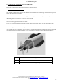
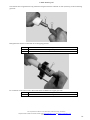
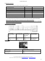
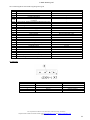
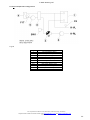
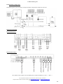
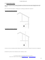
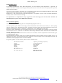
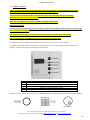
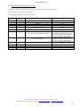
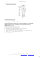
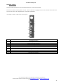
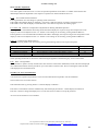
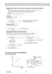
1
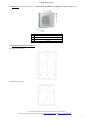
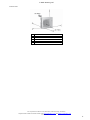
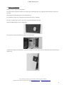
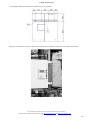
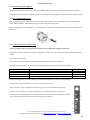
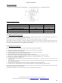
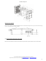
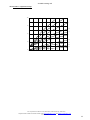
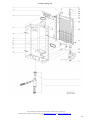
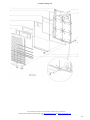
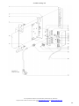
© MHG Heating Ltd ProCon Streamline Hybrid Unit. Installation and Operating Manual. Unit 4 Epsom Downs Metro Centre, Waterfield, Tadworth, Surrey, KT20 5LR Telephone 08456 448802 Fax 08456 448803 Email [email protected] Web DHWw.mhgheating.co.uk 010313 Draft 1 © MHG Heating Ltd Section 1.0 2.0 3.0 4.0 5.0 6.0 7.0 8.0 9.0 10.0 11.0 12.0 13.0 14.0 15.0 16.0 17.0 18.0 19.0 20.0 21.0 22.0 23.0 24.0 25.0 26.0 27.0 28.0 29.0 30.0 31.0 32.0 33.0 34.0 35.0 36.0 37.0 38.0 39.0 40.0 41.0 Appliance Type Installation Regulations and Requirements Appliance Warranties Dimensions Internal Unit Dimensions External Unit Installation Clearances Delivery and Mounting Technical Data Gas Boiler Module Technical Data Heat Pump Module Positioning the External Unit Installing the Refrigerant Pipework Electrical Connections Internal Hydraulic Configuration Hydraulic Configuration Single Heating Zone & Hot Water Hydraulic Configuration Dual Heating Zone & Hot Water Fluing Installation Options Fluing Options Balanced Flue Terminal Positions Pressure (Safety) Relief Valve Filling The Heating System Expansion Vessel System Water Quality Appliance Controls Default Controls Appliance Fault Codes (Heat Pump Controller) Appliance Fault Codes (Boiler Controller) Fuel Gas Conversation Procedure Boiler Controls Boiler Controller Adjustment Commissioning The Appliance Pre-Commissioning Checks Combustion System Commissioning Routine Inspection & Servicing Routine Service Inspection Routine Cleaning and Maintenance (Boiler Module) Routine Cleaning and Maintenance (Heat Pump) Fault Codes (Boiler Module) Weather Compensation Slope Exploded Spares Diagram (Boiler Module) Parts List Notes Page # 3 4 5 6 7 7 9 15 16 17 17 20 26 27 28 29 30 32 33 33 34 34 35 36 42 43 44 45 46 48 48 48 49 49 50 51 52 53 54 59 60 Additional Manuals Heat Pump Controller Manual Heat Pump External Unit Manual Unit 4 Epsom Downs Metro Centre, Waterfield, Tadworth, Surrey, KT20 5LR Telephone 08456 448802 Fax 08456 448803 Email [email protected] Web DHWw.mhgheating.co.uk 010313 Draft 2 © MHG Heating Ltd 1.0 Appliance Type The ProCon Streamline Hybrid unit is supplied complete with a 3-10kW air to water heat pump (COP 4.4), 7.7-26.8kW modulating condensing gas boiler and comprehensive controller. The heat pump module is designed as a split system. A suitably qualified F gas registered engineer is required to install and commission the interconnecting refrigerant pipework. The external unit is supplied with 3.2kg of R410A refrigerant which is sufficient for 10m (One way) of interconnecting refrigerant pipework. (Model PUHZ-SW75VHA.UK) The modulating gas condensing boiler can operate on either Natural Gas or LPG. (Conversion kit required). Kit Name Natural Gas LPG conversion kit External Unit Product Code 18.60000-9300 96.34344-7207 PUHZ-SW75VHA.UK Unit 4 Epsom Downs Metro Centre, Waterfield, Tadworth, Surrey, KT20 5LR Telephone 08456 448802 Fax 08456 448803 Email [email protected] Web DHWw.mhgheating.co.uk 010313 Draft 3 © MHG Heating Ltd 2.0 Installation Regulations and Requirements The installation of the Hybrid unit must be in accordance with the relevant requirements of Gas Safety (Installation & Use) Regulations 1994, Health & Safety at Work Act, Building Regulations, IEE Regulations, Construction (Design & Management) Regulations 1994, Local Authority Bye-Laws, National, Fire Regulations and Insurance Company requirements. The following Codes of Practice are also applicable:F Gas and ODS Regulations. BS 5440-1: 2008 Installation of flues and ventilation for gas appliances of rated input not exceeding 70 kW net (1st, 2nd and 3rd family gases). Part 1: Specification for the installation of flues. BS 5440-2: 2009 Installation of flues and ventilation for gas appliances of rated input not exceeding 70 kW net (1st, 2nd and 3rd family gases). Part 2: Specification for installation and maintenance of ventilation for gas appliances. BS 5449: 1990 Specification for forced circulation hot water central heating systems for domestic premises. BS 6644: 2011 Specification for gas fired hot water boilers of rated inputs between 70kW (net) and 1.8MW(net) (2nd and 3rd family gases). BS 6798: 1987 Specification for installation of gas fired hot water boilers of rated input not exceeding 60 kW. BS 6880: 1988 Code of Practice for low temperature hot water heating systems of output greater than 45kW. Parts 1, 2 & 3. BS 6891: 1988 Specification for installation of low pressure gas pipework of up to 28mm (R1) in domestic premises (2nd family gases) BS 7593: 1992 Code of Practice for treatment of water in domestic hot water central heating systems. BS 7671: 1992 Requirements for electrical installations. IEE Wiring Regulations. Sixteenth edition. CISBE Guide reference sections B7, B11 and B13. CP342 Part 2: 1974 Code of Practice for centralized hot water supply. IGE/UP/2 Gas installation pipework, boosters and compressors on industrial and commercial premises. IGE/UP/4 Commissioning of gas fired plant on industrial and commercial premises IGE/UP/10 Installation of gas appliances in industrial and commercial premises. Part 1: Flued appliances. And any addition prevailing regulation and or code of practice not detailed above. Unit 4 Epsom Downs Metro Centre, Waterfield, Tadworth, Surrey, KT20 5LR Telephone 08456 448802 Fax 08456 448803 Email [email protected] Web DHWw.mhgheating.co.uk 010313 Draft 4 © MHG Heating Ltd 3.0 Appliance Warranties All MHG appliances enjoy a full 36 month warranty as detailed in our terms and conditions. The guarantee period shall begin on the day of commissioning, or at latest 3 months after delivery has been made. The customer shall only be able to claim against MHG under guarantee if the commissioning of the object of delivery has been carried out by MHG staff or the authorized supplier, if the customer has followed MHG's instructions relating to the treatment and maintenance of the object of delivery and if no replacement parts of outside origin have been fitted. Parts subject to wear such as ignition electrodes, seals etc. are strictly excluded from the guarantee. In addition to the above warranties, the gas condensing boilers Primary Heat Exchangers carry a 60 month guarantee against manufacturing or material defect. Unit 4 Epsom Downs Metro Centre, Waterfield, Tadworth, Surrey, KT20 5LR Telephone 08456 448802 Fax 08456 448803 Email [email protected] Web DHWw.mhgheating.co.uk 010313 Draft 5 © MHG Heating Ltd 4.0 Dimensions Internal Unit. (H=910mm x W=780mm x D=300mm) Legend 1 2 2.1 3 4 4.1 5 6 7 Refrigerant Line Refrigerant Line Electrical Inlet Route Header Drain Heating Flow Condensate Outlet Gas Inlet Heating Return Flue Spigot 16mm 10mm 3 Clips ½” BSP 1” BSP ¾” Flexible ½” BSP 1” BSP Concentric 80/125 Unit 4 Epsom Downs Metro Centre, Waterfield, Tadworth, Surrey, KT20 5LR Telephone 08456 448802 Fax 08456 448803 Email [email protected] Web DHWw.mhgheating.co.uk 010313 Draft 6 © MHG Heating Ltd 5.0 Dimensions Evaporator External Unit. (H=943mm x W=950mm x D=330mm) (PUHZ-SW75VHA.UK) # A B C W Dimension 330 mm 943 mm 950 mm 75 kg 6.0 Installation and Service Clearances Internal Unit Front View Internal Unit Top View Unit 4 Epsom Downs Metro Centre, Waterfield, Tadworth, Surrey, KT20 5LR Telephone 08456 448802 Fax 08456 448803 Email [email protected] Web DHWw.mhgheating.co.uk 010313 Draft 7 © MHG Heating Ltd External Unit # A B C D E Minimum Clearance 50mm 750mm 250mm 250mm 100mm Unit 4 Epsom Downs Metro Centre, Waterfield, Tadworth, Surrey, KT20 5LR Telephone 08456 448802 Fax 08456 448803 Email [email protected] Web DHWw.mhgheating.co.uk 010313 Draft 8 © MHG Heating Ltd 7.0 Delivery and Mounting The hybrid unit is supplied on two pallets. The cased internal hydraulic assembly and separate gas condensing boiler on one pallets and the external evaporator on the other. Please dispose of all packaging in an environmental way. It is advisable to remove the casing from the internal units prior to installing. The case is secured with 2 screws. The screws are located behind the blue door. Rotate the MHG badge to expose a finger hole. Once open the control panel and case fixing screws can be seen. The left hand casing can be lifted clear of the unit once the screws have been removed. Followed by the interlocked right hand casing. Unit 4 Epsom Downs Metro Centre, Waterfield, Tadworth, Surrey, KT20 5LR Telephone 08456 448802 Fax 08456 448803 Email [email protected] Web DHWw.mhgheating.co.uk 010313 Draft 9 © MHG Heating Ltd The hanging bracket measurements are detailed below. (A = Bracket) Hang the two internal units onto the wall bracket and ensure the hydraulic connections 1 are secured with washers. Unit 4 Epsom Downs Metro Centre, Waterfield, Tadworth, Surrey, KT20 5LR Telephone 08456 448802 Fax 08456 448803 Email [email protected] Web DHWw.mhgheating.co.uk 010313 Draft 10 © MHG Heating Ltd Install the 3/8” vent valve and ½” drain valve as indicated. #13indicated below. Legend Item 1 2 3 4 5 6 7 8 9 10 11 12 13 Description Heat Pump Heat Meter (Optional) Low Loss Header Boiler Control Panel Controller Display Boiler PCB Flow Switch Common Flow Sensor Unit Circulating Pump (Boiler/Header) 3 Way Diverting Valve (Heat Pump/Boiler) Cable Entry Route Heat Pump Circulating Pump Heat Pump Return Sensor Drain Cock Unit 4 Epsom Downs Metro Centre, Waterfield, Tadworth, Surrey, KT20 5LR Telephone 08456 448802 Fax 08456 448803 Email [email protected] Web DHWw.mhgheating.co.uk 010313 Draft 11 © MHG Heating Ltd The following electrical connections must be made/checked for security. # 1 2 Description Common Flow Senor F8 Unit Circulating Pump # 3 4 Description HWS Enable from Heat Pump Control to the Boiler Flow Switch # Description Remove the Control Panel Securing screw to access the wiring Terminals for the Outside Air Sensor and RT Boiler Enable 5 Unit 4 Epsom Downs Metro Centre, Waterfield, Tadworth, Surrey, KT20 5LR Telephone 08456 448802 Fax 08456 448803 Email [email protected] Web DHWw.mhgheating.co.uk 010313 Draft 12 © MHG Heating Ltd # 6 # 7 # 8 Description Wiring Terminal X 4 RT Enable Terminals 6 & 7 Outside Air Sensor Terminals 8 & 9 (Fitted on a North or North East facing wall.) Description Route the RT Enable as shown. Secure the control panel with the screw Description Connect the boilers power supply to terminals 27, 28 & 29 Unit 4 Epsom Downs Metro Centre, Waterfield, Tadworth, Surrey, KT20 5LR Telephone 08456 448802 Fax 08456 448803 Email [email protected] Web DHWw.mhgheating.co.uk 010313 Draft 13 © MHG Heating Ltd # 1 Description In addition to the boilers outside air sensor the Heat Pump module must have an outside air sensor fitted on a North or North East facing wall. Minimum CSA 1.00 mm up to 20m. 1.5mm from 21-100m Wired to F9 / M Additional sensors can be wired to the sensor terminal rail depending upon the system design. (Bold indicates required.) # Sensor Function Location Voltage / Wire 41.0/F9 Outside Air Sensor (Required) North/North East Facing Wall <24 Volt / 4 Core / Screened 42.6/F8 Common Flow Sensor Internal <24 Volt / 2 Core / Screened 43.0/F6 Hot Water Sensor External Calorifier <24 Volt / 2 Core / Screened 40.1/F5 Heating Circuit 2 Flow Sensor Heating System (If a 3 port valve is used.) <24 Volt / 2 Core / Screened 44.0/F3 Thermal Store Sensor (Upper) External Buffer (Infrequently used) <24 Volt / 2 Core / Screened 44.2/F2 Thermal Store Sensor (Middle) External Buffer (Infrequently used) <24 Volt / 2 Core / Screened 44.1/F1 Thermal Store Sensor (Lower) External Buffer (Infrequently used) <24 Volt / 2 Core / Screened 40.0/F11 Heating Circuit 1 Flow Sensor Heating System (If a 3 port valve is used.) <24 Volt / 2 Core / Screened 43.1/F12 Hot Water Sensor (Lower) Multifunctional Relay 2 (MF2) <24 Volt / 2 Core / Screened F/13 No Function Within Hybrid Multifunctional Relay 3 (MF3) 45.0/F14 Solar Collector Sensor Optional Solar Panel (MF4) F15 No Function Within Hybrid ~ 42.3/F17 Heat Pump Return Senor Internal to Unit <24 Volt / 2 Core / Screened CAN Communication Ports ~ <24 Volt / 4 Core / Screened BM Room Unit Heated Space <24 Volt / 4 Core / Screened BMT Heat Pump Controller Internal <24 Volt / 4 Core / Screened <24 Volt / 2 Core / Screened Unit 4 Epsom Downs Metro Centre, Waterfield, Tadworth, Surrey, KT20 5LR Telephone 08456 448802 Fax 08456 448803 Email [email protected] Web DHWw.mhgheating.co.uk 010313 Draft 14 © MHG Heating Ltd 8.0 Technical Data Gas Condensing Boiler Module Description Product Number Weight Dimensions Primary Water Content Unit Kg mm L Heat Exchanger Construction Heating Flow & Return Gas Supply Inlet Flue Gas/Combustion Air Nominal Input Nominal Output 80/60°C Nominal Output 50/30°C Nominal Efficiency 80/60°C Nominal Efficiency 50/30°C Nominal Efficiency 40/30°C Maximum Flow Temperature Nominal Mass Flow Rate @20 ΔT Maximum Operating Pressure Maximum Inlet Gas pressure Minimum Inlet Gas Pressure Nominal Power Input Installation Categories Residual Flue Gas Pressure Flue Gas Temperature @ 80/60°C mm mm mm kW kW kW % % % °C L/h bar mbar mbar (Nat/LPG) V / Hz CE-0063AR3527 64 H 910mm x W 780mm x D 300mm 1.4 Copper Water Ways & Aluminum Flue Ways 22 15 80/125 7.2 – 27.3 7.0 – 26.2 7.7 – 26.8 97.2 – 96.0 98.2 – 106.9 101.0 – 108.5 75 1160 3 50 18/35 230/50 B23, B33, C13X , C33X, C43X, C53X, C63X, C83X Pa °C 90 94 Unit 4 Epsom Downs Metro Centre, Waterfield, Tadworth, Surrey, KT20 5LR Telephone 08456 448802 Fax 08456 448803 Email [email protected] Web DHWw.mhgheating.co.uk 010313 Draft 15 © MHG Heating Ltd 9.0 Technical Data Heat Pump Module (PUHZ-SW75VHA.UK) System Air/Water Model PUHZ-SW75VHA.UK Heat output in 7 output levels kW Heat 7,2 (3,1-10,5) Range of use for heating °C -20 to +24 Max. flow temperature for hot water °C 60 Max. heat output / Compressor frequency at A10/W 35 kW / Hz / COP1) 10,5 / 99 / 4,4 Max. heat output / Compressor frequency at A7/W35 kW / Hz / COP1) 10 / 96 / 4,3 Max. heat output / Compressor frequency at A2/W35 kW / Hz / COP 1) 7,2 / 96 / 3,4 Max. heat output / Compressor frequency at A2/W35 kW / Hz / COP 1) 5,1 / 61 / 3,9 Max. heat output / Compressor frequency at A-7/W35 kW / Hz / COP1) 4,8 / 99 / 2,5 kW / Hz / COP 1) 3,8 / 99 / 1,9 kW / Hz / COP 1) 9,4 / 99 / 3,4 Max. heat output / Compressor frequency at A2/W45 kW / Hz / COP 1) 7,0 / 96 / 2,8 Max. heat output / Compressor frequency at A-7/W45 kW / Hz / COP1) 5,2 / 99 / 2,2 Max. heat output / Compressor frequency at A-15/W35 Max. heat output / Compressor frequency at A7/W45 kW / Hz / COP 1) 4,3 / 116 / 1,5 kW / Hz / COP 1) 10,4 / 94 / 3,0 Max. heat output / Compressor frequency at A7/W55 kW / Hz / COP 1) 7,9 / 89 / 2,5 Max. heat output / Compressor frequency at A-7/W55 Refrigerant / Base fill kW / Hz / COP1) 3,1 / 95 / 1,1 -- / kg R 410A2) / 3,2 Refrigerant, Additional volume 10-50m g/m 60 Water volume flow at Δt 5K (level 6) m³/h 1,2 Volume flow, air (exterior unit) m³/h 3300 Max. operating pressure water Bar 3,0 Hydraulic connection flow/return BSP 1“ AG Diameter of cooling lines, liquid mm 10 Diameter of cooling lines, gas mm 16 Max. single length m 50 Max. difference in elevation m 30 Max. heat output / Compressor frequency at A-15/W45 Max. heat output / Compressor frequency at A20/W 55 Sound pressure level (for exterior unit) dB(A) 383) Dimensions of interior unit (H x W x D) mm 910x780x300 Dimensions of exterior unit (H x W x D) mm 943x950x330 Weight of interior unit kg 85 Weight of exterior unit kg 75 V / Hz 1 NPE 230 V 50 Hz A 16 Electricals internal unit Power supply system Fuse on site, Tripping characteristic B Electricals external unit Power supply system V / Hz 1 NPE 230 V 50 Hz Starting current max. A 19 Operating current A 9,74 kW 2,32 A 20 Rated power consumption Fuse on site (exterior unit), Tripping characteristic C Unit 4 Epsom Downs Metro Centre, Waterfield, Tadworth, Surrey, KT20 5LR Telephone 08456 448802 Fax 08456 448803 Email [email protected] Web DHWw.mhgheating.co.uk 010313 Draft 16 © MHG Heating Ltd 10.0 Positioning the External Unit (PUHZ-SW75VHA.UK) Please refer to the External Unit’s technical manual for complete guidance. 11.0 Installing the Refrigerant Pipework Only a suitably qualified F Gas engineer shall undertake the installation and commissioning of the refrigerant pipework between the internal and external units. Failure to install and commission the refrigerant pipework correctly will invalidate the appliances warranty. Additional guidance can be found in the External Unit’s manual. The interconnecting pipework is 10mm and 16mm. In order to connect the refrigerant line and the electrical cables to the exterior unit the wall must be breached. The breach/hole must be a min. of Ø 70 mm and 10 mm gradient from inside to outside. To avoid damage the breach/hole should be padded from within as detailed below and lined with a PVC pipe. After assembly has been completed the wall breach/hole on site should be sealed with an appropriate sealing compound in accordance with fire prevention regulations. Do not use substances containing cement or lime for this purpose. # 1 2 3 4 Description Communication / Control Cable 10mm Refrigerant Pipe Communication / Control Cable 16mm Refrigerant Pipe Unit 4 Epsom Downs Metro Centre, Waterfield, Tadworth, Surrey, KT20 5LR Telephone 08456 448802 Fax 08456 448803 Email [email protected] Web DHWw.mhgheating.co.uk 010313 Draft 17 © MHG Heating Ltd The external unit is supplied with 3.5kg of R410A refrigerant which is sufficient for 10m (One Way) of interconnecting pipework. Refrigerant lines must be countersunk to avoid clipping particles # 1 2 Description Refrigerant Pipework Countersink Tool For connection to the exterior unit a flare border must be added to the copper pipe ends. # Description 3 Bordering Tool Unit 4 Epsom Downs Metro Centre, Waterfield, Tadworth, Surrey, KT20 5LR Telephone 08456 448802 Fax 08456 448803 Email [email protected] Web DHWw.mhgheating.co.uk 010313 Draft 18 © MHG Heating Ltd Please ensure that the correct border dimensions are adhered to. Copper Pipe External Diameter 10mm 16mm Border Dimensions 12.8 – 13.2 mm 19.3 – 19.7 mm Ensure that the correct tightening Torque is used. Diameter 3/8” 5/8” Tightening Torque 32-40 Nm 65-75 Nm If any brazing/welding work is undertaken on the refrigerant line, a protective gas (i.e. nitrogen) will need to be passed through the pipe in order to prevent scale formation. Scale and other contamination can impair the proper operation of the device leading to premature failure which will not be covered by the unit’s warranty. Unit 4 Epsom Downs Metro Centre, Waterfield, Tadworth, Surrey, KT20 5LR Telephone 08456 448802 Fax 08456 448803 Email [email protected] Web DHWw.mhgheating.co.uk 010313 Draft 19 © MHG Heating Ltd 12.0 Electrical Connections Both the internal and external units require suitably rated power supplies. Electricals internal unit Power supply system Fuse on site, Tripping characteristic B Electricals external unit Power supply system Starting current max. Operating current Rated power consumption Fuse on site (exterior unit), Tripping characteristic C V / Hz 1 Phase 230 V 50 Hz A 16 V / Hz 1 Phase 230 V 50 Hz A 19 A 9,74 kW 2,32 A 20 A 3 core and earth link from the internal unit to the external unit provides control and operational data feedback. Please note that a power supply for the external unit is present within the internal unit Please ensure that the power supplies to both the internal and external units are isolated prior to undertaking work on either unit to prevent electrical shocks. Internal Unit Power Connections 3=L, 6=N, 8=E. Output to Heating Pump 3 Core 230V 1 Amp External Unit LNE Unit Power Supply. 3 Core 230V Single Phase 25 Amp Supply. 17=L, 18=N, 19=E. Output to HWS Pump 3 Core 230V 1 Amp 23=S1, 24=S2, 25=S3, 22=Earth Internal unit to External unit Control 3 Core + Earth 230V 5 Amp 32=L, 31=N, 30=E. Unit Power Supply. 3 Core 230V Single Phase 10 Amp Supply. S1, S2, S3. Earth Internal unit to External unit Control 3 Core + Earth 230V 5 Amp Unit 4 Epsom Downs Metro Centre, Waterfield, Tadworth, Surrey, KT20 5LR Telephone 08456 448802 Fax 08456 448803 Email [email protected] Web DHWw.mhgheating.co.uk 010313 Draft 20 © MHG Heating Ltd Internal Wiring Internal Wiring Diagram Heat Pump Module Unit 4 Epsom Downs Metro Centre, Waterfield, Tadworth, Surrey, KT20 5LR Telephone 08456 448802 Fax 08456 448803 Email [email protected] Web DHWw.mhgheating.co.uk 010313 Draft 21 © MHG Heating Ltd Internal Wiring Diagram Heat Pump Module Main # Sub # Sub # Description X12 (TB141) 5/6 Compressor Relay Heating Zone 1 Pump X12 (TB142) 1/2 Compressor A2 Relay Heating Zone 2 Pump X11 (S1) 1/2 3 /4 Main Power Switch L Main Power Switch N A3 Relay Hot Water Pump 1 Compressor Operating Indicator Lamp 2 Indicator Lamp Neutral 1 Hand Mode Indicator Lamp 2 1 Indicator Lamp Neutral Automatic Operation 2 Live in to Hand Auto Switch 3 Hand Operation 1 /2 Unit Fuse 6.3 A 1 2 3 4 5 6/7 8/9 10 11 12 13/14 15/16 17 18/19 20/21 22 Power Supply Company Control EU Power Supply Company Control EU Heating Zone 1 Power Output Heating Zone 1 Valve Open Output Heating Zone 1 Valve Close Output Common Neutral Common Earth Heating Zone 2 Power Output Heating Zone 2 Valve Open Output Heating Zone 2 Valve Close Output Common Neutral Common Earth Hot Water Pump Output Common Neutral Common Earth External Unit Earth S1 230Volt Communication to External Unit S2 Ground Communication to External Unit S3 24V Communication to External Unit Neutral For Unit Pump Neutral For Gas Condensing Boiler 230 V Power Supply to Gas Condensing Boiler Earth For Gas Condensing Boiler Main Earth Input Main 230V Neutral Input Main 230V Live Input A5 A6 A7 A8 A9 KR (X2) Main # A1 A4 X13 Description Maximum output loading 1Amp per output Total loading 6.3 amp Relay Heating Zone 2 Mixing Valve Open Relay Heating Zone 2 Mixing Valve Close Relay Heat Pump Enable Relay Gas Boiler Enable Relay Heating Zone 2 Mixing Valve Open Relay Heating Zone 2 Mixing Valve Close A10 Relay Heat Pump Pump A12 E1 E2 1 2 3 4 5/6 7 8 4/5 6/7 8 9/10 Relay Unit Pump Power Supply Company Control Not Used Not Used Power Supply to Gas Boiler L Power Supply 3 Way Valve L Power Supply to Gas Boiler N Not Used Power Supply 3 Way Valve N Power Supply 3 Way Valve L* Not Used Heating Enable (Volt Free) Not Used Hot Water Enable (Volt Free) X11 (b1) X11 (b2) X11 (S2) X11 (6.3AT) X10 23 24 KR (X14) 11/12 Not Used 25 26 27 28 29 30 31 32 *Permanent Live for 3 Way Valve Item UV1 K6 K8 K3 K9 P1 P2 SW1 Description 3 Way Valve Heat Pump Enabling Relay Boiler Enabling Relay Hot Water Control Manual Override to Enable The Gas Boiler and Pump Unit Pump Heat Pump Pump Flow Switch Unit 4 Epsom Downs Metro Centre, Waterfield, Tadworth, Surrey, KT20 5LR Telephone 08456 448802 Fax 08456 448803 Email [email protected] Web DHWw.mhgheating.co.uk 010313 Draft 22 © MHG Heating Ltd Internal Unit Sensor Terminals (All sensor/inputs are twin core with the second core connecting to the terminal below) # Sensor Function Location Voltage / Wire 41.0/F9/ Outside Air Sensor (Required) North/North East Facing Wall <24 Volt / 4 Core / Screened 42.6/F8 Common Flow Sensor Internal <24 Volt / 2 Core / Screened 43.0/F6 Hot Water Sensor External Calorifier <24 Volt / 2 Core / Screened 40.1/F5 Heating Circuit 2 Flow Sensor Heating System (If a 3 port valve is used.) <24 Volt / 2 Core / Screened 44.0/F3 Volt Free Heating Enable* Via a Volt Free Room Unit <24 Volt / 2 Core / Screened 44.2/F2 Thermal Store Sensor (Middle) External Buffer <24 Volt / 2 Core / Screened 44.1/F1 Thermal Store Sensor (Lower) External Buffer <24 Volt / 2 Core / Screened 40.0/F11 Heating Circuit 1 Flow Sensor Heating System (If a 3 port valve is used.) <24 Volt / 2 Core / Screened 43.1/F12 Hot Water Sensor (Lower) Multifunctional Relay 2 (MF2) <24 Volt / 2 Core / Screened F/13 No Function Within Hybrid Multifunctional Relay 3 (MF3) 45.0/F14 Solar Collector Sensor Optional Solar Panel (MF4) F15 0-10 Volt Control Input External Controller 42.3/F17 Heat Pump Return Senor Internal to Unit <24 Volt / 2 Core / Screened CAN Communication Ports ~ <24 Volt / 4 Core / Screened BM Room Unit Heated Space <24 Volt / 4 Core / Screened BMT Heat Pump Controller Internal <24 Volt / 4 Core / Screened <24 Volt / 2 Core / Screened *If a timed volt free enable is used, all heating time switches should be set to ON --:-- OFF --:-- Unit 4 Epsom Downs Metro Centre, Waterfield, Tadworth, Surrey, KT20 5LR Telephone 08456 448802 Fax 08456 448803 Email [email protected] Web DHWw.mhgheating.co.uk 010313 Draft 23 © MHG Heating Ltd Internal Wiring Diagram Gas Condensing Boiler Unit 4 Epsom Downs Metro Centre, Waterfield, Tadworth, Surrey, KT20 5LR Telephone 08456 448802 Fax 08456 448803 Email [email protected] Web DHWw.mhgheating.co.uk 010313 Draft 24 © MHG Heating Ltd Gas Condensing Boiler Internal Wiring Diagram Legend Item AF BpKR DP EA EAW GVZ G IZ KR NS PC RL RT UV1 VL WS DHW X1 X2 X3 X4 X5 X6 X7 X14 ZES Description Outside Air Sensor Common Earth Rail Display Fascia Common Earth Rail Combustion/Heat Exchanger Chamber Earth Connector Gas Valve & Ignition Transformer/Rectification Unit Combustion Fan Ignition / Rectification Electrode Controller PCB Power Supply Notebook Interface Connection Return Sensor Boiler Enable 3 Way Valve Flow Sensor Resistor 220 Ohm 5W HWS Relay K3 Gas Valve and Ignition Output 3 Way Valve and Power In Combustion Fan External Sensor Input and Boiler Enable PC Interface No Function Internal Sensor Input Relay Interface Within Heat Pump Module Ignition Electrode Cap 1k ohm Associated Terminals. Block X4 Terminals 8 & 9 ~ ~ ~ ~ ~ ~ ~ ~ Block 2 Terminals 2 L & 4 N ~ ~ Block 4 Terminals 7 & 8 Block 2 Terminals 7 & 8 ~ ~ ~ 230 Volt 230 Volt 24 Volt 24 Volt 24 Volt ~ 24 Volt 230 Volt / 24 Volt ~ Terminal X1 Terminal 1 2 3 4 -- Colour Red Black Blue Brown Green / Yellow Description Rectification Live Gas Valve Neutral Ignition Neutral Protective Earth Unit 4 Epsom Downs Metro Centre, Waterfield, Tadworth, Surrey, KT20 5LR Telephone 08456 448802 Fax 08456 448803 Email [email protected] Web DHWw.mhgheating.co.uk 010313 Draft 25 © MHG Heating Ltd 13.0 Internal Hydraulic Configurations Legend # 1 2 3 4 5 6 F8 F17 K-VL K-RL SW1 Description Gas Condensing Boiler Hybrid Pump 3 Way Diverting Valve Heat Pump Heat Exchanger Heat Pump Pump Heat Pump Low Loss Header Hybrid Common Flow Senor Heat Pump Return Senor Hybrid Flow Pipe Hybrid Return Pipe Hybrid Flow Switch Unit 4 Epsom Downs Metro Centre, Waterfield, Tadworth, Surrey, KT20 5LR Telephone 08456 448802 Fax 08456 448803 Email [email protected] Web DHWw.mhgheating.co.uk 010313 Draft 26 © MHG Heating Ltd 14.0 Hydraulic Configuration Single Heating Zone system with direct on Hybrid weather compensation and priority hot water. Electrical Connections Internal Unit Power. Internal Unit Sensors *If a timed volt free enable is used, all heating time switches should be set to ON --:-- OFF --:-- Unit 4 Epsom Downs Metro Centre, Waterfield, Tadworth, Surrey, KT20 5LR Telephone 08456 448802 Fax 08456 448803 Email [email protected] Web DHWw.mhgheating.co.uk 010313 Draft 27 © MHG Heating Ltd 15.0 Hydraulic Configuration Dual Heating Zone system with direct on Hybrid weather compensation and priority hot water. Electrical Connections Internal Unit Power. Internal Unit Sensors *If a timed volt free enable is used, all heating time switches should be set to ON --:-- OFF --:-Unit 4 Epsom Downs Metro Centre, Waterfield, Tadworth, Surrey, KT20 5LR Telephone 08456 448802 Fax 08456 448803 Email [email protected] Web DHWw.mhgheating.co.uk 010313 Draft 28 © MHG Heating Ltd 16.0 Fluing Installation Options When flues are installed with horizontal sections/portions a 3 0 fall back to the boiler must be maintained. This will not only ensure condensate removal preventing premature seal failure, but also prevent nuisances dripping from the wall terminal. Please ensure that the flue adapter is installed prior to installing any addition flue components . Concentric Wall Terminal Configuration Concentric Roof Terminal Configuration The boiler can also be installed open flued, taking air from the room. DN 80 Components are used in this configuration. Flexible flues systems are also available with coils available up to 50M. Unit 4 Epsom Downs Metro Centre, Waterfield, Tadworth, Surrey, KT20 5LR Telephone 08456 448802 Fax 08456 448803 Email [email protected] Web DHWw.mhgheating.co.uk 010313 Draft 29 © MHG Heating Ltd 17.0 Fluing Options Please note that excessive resistance within the flue and combustion air supply systems will lead to a reduction in the output of the appliance and induce operational faults. 80/125mm Concentric Flue Components Wall Terminal Vertical Terminal 955mm Flue Extension 500mm Flue Extension 255mm Flue Extension 87º Bend 45º Bend 30º Bend Hybrid (Pa Resistances) 5.0 5.0 4.0 2.0 1.5 4.0 2.0 1.5 80mmØ PPS Flue Components Exhaust Pipe Terminal Air Pipe Terminal 955mm Flue Extension 500mm Flue Extension 255mm Flue Extension 87º Bend 45º Bend 30º Bend (Pa Resistances) 2.5 4.0 3.0 1.5 1.0 3.0 1.5 1.0 Unit 4 Epsom Downs Metro Centre, Waterfield, Tadworth, Surrey, KT20 5LR Telephone 08456 448802 Fax 08456 448803 Email [email protected] Web DHWw.mhgheating.co.uk 010313 Draft 30 © MHG Heating Ltd Unit 4 Epsom Downs Metro Centre, Waterfield, Tadworth, Surrey, KT20 5LR Telephone 08456 448802 Fax 08456 448803 Email [email protected] Web DHWw.mhgheating.co.uk 010313 Draft 31 © MHG Heating Ltd 18.0 Balanced Flue Terminal Positions For Boilers Below 70kW Net Input (All measurements are in mm and are minimum clearances.) A B C D E F G H I J K L M N P Q R S Terminal Location *Below and opening window etc. Below gutter soil pipes etc. Below Eaves. *Below balconies or car port roof. From vertical drain or soil pipe etc. From internal or external corners. Above ground or balcony level. From a surface facing the terminal. From a terminal facing the terminal. *From opening in a carport into a dwelling. Vertically from a terminal on the same wall. Horizontally from a terminal on the same wall. Above an opening, window etc. *Horizontally to an opening, window etc. Above a level roof (base of terminal.) From an adjacent wall (edge of terminal.) From adjacent opening, window etc. From any other flue terminal. Boilers with a rated Input < 70kW Net 300 75 200 200 150 300 300 2000 2000 1200 1500 300 500 300 500 500 1000 600 * Positions not recommended. Groups of appliances of 150kW gross input (136kW net input) and above must comply with the Clean Air Act with respect to the chimney discharge height. The terminal/s shall be guarded if it is less than 2000mm above the ground or in any position where it may cause injury to persons resulting from touching a hot surface. Absolute guidance must be sought from the respective regulation. Unit 4 Epsom Downs Metro Centre, Waterfield, Tadworth, Surrey, KT20 5LR Telephone 08456 448802 Fax 08456 448803 Email [email protected] Web DHWw.mhgheating.co.uk 010313 Draft 32 © MHG Heating Ltd 19.0 Pressure (Safety) Relief Valve In accordance with the prevailing British Standard 5440/6644, the installer shall install as suitably sized Pressure (Safety) Relief Valve. The location of this valve is important with respect to the applied pressure of the units circulation pump, it is therefore recommended to locate the Pressure (Safety) Relief Valve on the return pipe immediately adjacent to the heat generator; furthermore, there must not be any means of isolation between the unit and the Pressure (Safety) Relief Valve. To assist with the correct positioning of the pressure relief valve hydraulic connector kits are available as an optional extra. 20.0 Filling The Heating System The Initial filling of a sealed heating system, and subsequent refilling, must be by a method that has been approved by the Water Regulation Advisory Scheme (WRAS) for that type of heating system. i.e. Domestic (In-House) Non Domestic (Other than In-House) Fluid Category 3 (C-3) Fluid Category 4 (C-4) For Category 3 systems, the approved method of filling must comprise of the following components in the arrangement shown; Control Valve incorporating a Double Check Valve on the Mains Cold Water pipework. Temporary Connecting Hose, which must be disconnected after use. Control Valve, on the heating system. For Category 4 systems, the approved method of filling must comprise of the following components in the arrangement shown; Control Valve. Strainer. Verifiable Backflow Device with Reduced Pressure Zone (RPZ Valve). Incorporating a ‘Type BA’ Air Gap. Tundish. Control Valve. Furthermore, in accordance with BS 6644: 2005 system with an input greater than 70kW (nett), an automatic water replenishment unit shall be installed to automatically replenish any lost or evaporated water. Please refer to BS 6644: 2005 for allowable water replenishment methods for use with sealed/pressurized heating systems. For information on a comprehensive range of pressurization units that comply with current British Standards and WRAS Regulations, please contact MHG Heating Ltd Sales. Unit 4 Epsom Downs Metro Centre, Waterfield, Tadworth, Surrey, KT20 5LR Telephone 08456 448802 Fax 08456 448803 Email [email protected] Web DHWw.mhgheating.co.uk 010313 Draft 33 © MHG Heating Ltd 21.0 Expansion Vessel In accordance with BS 6644: 2005, WRAS Regulations, and Local Authority Water Regulations, as applicable, the installer shall install a suitably sized, and approved, Expansion Vessel to ensure that the water capacity of the system has ample expansion capacity. The location of the expansion vessel shall only be isolatable from the system via a Lockable Type Service Valve, which shall be locked in the OPEN position, to prevent accidental isolation. Furthermore, a drain facility should be provided adjacent to the expansion vessel to aide the routine maintenance, overhaul, of the vessels Air Pressure setting. For information on a comprehensive range of expansion vessels that comply with current British Standards and WRAS Regulations, please contact MHG Heating Ltd Sales. 22.0 System Water Quality Water Treatment, System Cleaning (BS 7592: 2006)(Building Regulations Part L). The entire primary system MUST be thoroughly cleaned and flushed to remove debris, flux residues, etc. before opening the boiler isolation valves & flooding the boiler. Particular care must be taken where the Hybrid boiler is being retrofitted into an old/existing system, as system silt or magnetite can be very damaging to the new unit. Following cleaning and flushing the system MUST be dosed with a good quality water treatment to prevent corrosion and the formation of scale. FAILURE TO OBSERVE THESE REQUIREMENTS WILL RENDER THE WARRANTEE ON THE APPLIANCE VOID. Cleaning, flushing and water treatment must be carried out in accordance with the requirements of BS 7592:2006, prior to commissioning the boiler. Repeated draining and refilling of the system, without replenishment of water treatment, must be avoided, as this is very damaging to the boiler. The boiler must not operate without the system water being correctly and adequately treated, and maintained, with an appropriate level of corrosion inhibitor. For specific guidance on water treatment, direct contact is advisable with:Betz Dearborn Limited (Sentiel) Foundry Lane Widnes Cheshire WA8 8UD Tel: 0151 424 5351 Fax: 0151 420 5447 Alpha-Fry Technologies (Fernox) Cookson Electronics Forsyth Road Sheerwater Woking Surrey GU21 5RZ Tel: 0208 665 6666 Fax: 0208 665 4695 Unit 4 Epsom Downs Metro Centre, Waterfield, Tadworth, Surrey, KT20 5LR Telephone 08456 448802 Fax 08456 448803 Email [email protected] Web DHWw.mhgheating.co.uk 010313 Draft 34 © MHG Heating Ltd 23.0 Appliance Controls Prior to activating the unit for the first time please ensure that all services, systems and sensors have been installed, checked, flushed, all pumps & valves are bled and free to operate. A self test mode is initiated by both the internal and external units. This may take up to 10 minutes. Within this period the units will not operate. When power is applied to the unit the controller will display END and OK. END must be selected. If OK is pressed the installation menu can be adjusted from the factory defaults. If alterations are made the unit may not function as designed. If no button is pressed within 5 Seconds the screen will refresh to the standard operating mode. The Green Lamp must stop flashing before any programing can be undertaken. The appliances control / display panel provides access to the majority of the units control settings. A separate control panel is mounted on the gas condensing boiler. Once commissioned this panel should not need adjusting. (Detail for this panel is provided later in this manual). # 1 2 3 4 5 Description Main Power Switch Heat Pump Operation Indicator Manual Override Button Commissioning Mode Automatic / Manual Operation Switch Main Fuse (6.3 Amp) Adjustment of the controller is undertaken via the HOME BUTTON, the DISPLAY BUTTONS and the INFO WHEEL. Unit 4 Epsom Downs Metro Centre, Waterfield, Tadworth, Surrey, KT20 5LR Telephone 08456 448802 Fax 08456 448803 Email [email protected] Web DHWw.mhgheating.co.uk 010313 Draft 35 © MHG Heating Ltd Controls Function Provides access to the setting parameters screen from a default screen. Returns the screen to a default screen from a parameter setting screen. Provides access to the second level information of the displayed value. Selects a value to be altered by the INFO WHEEL. Stores the new value. Changes the default display when more than four lines are available. Changes the set value within the parameter setting mode. Additional Controller information can be found in the Controller Manual at the rear of this manual. 24.0 Controller Defaults The controller has been preset to allow the unit to operate and provide the optimum operating efficiency. The operating mode of the unit can be adjusted by pressing the lower DISPLAY BUTTON, using the INFO WHEEL and pressing the lower DISPLAY BUTTON to store the setting. If the unit fails to operate please check the operation of all associated pumps, valves, enabling circuits prior to adjusting any settings. Unit 4 Epsom Downs Metro Centre, Waterfield, Tadworth, Surrey, KT20 5LR Telephone 08456 448802 Fax 08456 448803 Email [email protected] Web DHWw.mhgheating.co.uk 010313 Draft 36 © MHG Heating Ltd End user parameterization Key sequence: Home Controller User Description System Mode of operation Language LCD Contrast LCD Brightness Date and Time Time Master °C / °F Range Default Off/On Automatic 1 English 4 30 -20 to + 20 00-30 00:00-24:00 / 1-7 On / Off Celsius, Fahrenheit Warm Water (DHW) 1x Warm Water T-DHW 1 Target T-DHW 2 Target T-DHW 3 Target BoB-Value Circ with DHW Prog Anti-legionella Off/On 10-70°C 10-70°C 10-70°C 0 K - 70 K Off/On Off/On As Left On Celsius Off 50°C 50°C 50°C 0K Off Off Factory parameterization (HP) heating technician Key sequence: Home Controller Technician Description Range Default As Left Heating circuit (HK) 1 / 2 Mode of operation T-Room Target 1 T-Room Target 2 T-Room Target 3 T-Reduced T-Absent T-Room cool Min TA cool T-Flow Constant Target T-Flow Constant Reduced Standby, Automatic 1/2, Summer, Heat, Reduced Standby, Automatic 1/2, Summer, Heat, Reduced 5-40°C 5-40°C 5-40°C 5-40°C 5-40°C ----, 20-40°C ----, 0-40°C 10-110°C 10-110°C HK 1: ---HK 2: ---20°C 20°C 20°C 18°C 15°C 25°C 27°C 45°C 30°C Unit 4 Epsom Downs Metro Centre, Waterfield, Tadworth, Surrey, KT20 5LR Telephone 08456 448802 Fax 08456 448803 Email [email protected] Web DHWw.mhgheating.co.uk 010313 Draft 37 © MHG Heating Ltd Description Heat limit day Heat limit night Heat curve Rad adaption Influence of room Adjust Room Unit Heat optimum Max on-time Low Optimum PC Release Configuration Terminal Change code Controller Address BUS-ID HK1 BUS-ID HK2 eBUS supply* System selection Control type HS1 type Gradient HS BUS HS2 type HS2 reservoir HS3 type HS4 type Buffer Cooling operation (optional)** F15 Function E1 Function E2 Function Sensor Heat source Max T-HS1 Min T-HS1 Min T-HS2 Max T-Accumulator Min T-Accumulator Starting-load relief Min limit Hysteresis (or Hyst HS) Hysteresis Time Change of sequence Clock inhibition Hysteresis burner 2 Range Default ----, -5°C to +40°C ----, -5°C to 40°C 0,00-3,00 (U/F=1.1. Rads=2.5) OFF/ON 00-20 -5,0 to +5,0 K Off, T-Reduced, T-Room 0:00-3:00 h 0:00-3:00 h 0000-9999 19°C 16°C 1.1 Off 0 0,0 K Off 0:00 h 0:00 h 0 00-05 00-22 00-03 00-09 00-09 00, 01, 02 Off/On 00-08 00-03 00-03 1k / 5k Sensors On 3000 1 1 2 Off 7 6 7 Off 5 1 0 1 0 0 Off 8 2 0 5k 30-110°C 10-80°C 10-80°C 30-110°C 10-80°C 10-85°C 00, 01, 02 5-20K 00-30 min. 00-800 h 00-30 min. 2-20 K 85°C 10°C 10°C 95°C 10°C 10°C 0 5K 00 min. 00 h 00 min. 2K 0000-9999 01-16 (00), 01-15 (00), 01-15 Off/On ----, 01-13 00-06 00-09 As Left Unit 4 Epsom Downs Metro Centre, Waterfield, Tadworth, Surrey, KT20 5LR Telephone 08456 448802 Fax 08456 448803 Email [email protected] Web DHWw.mhgheating.co.uk 010313 Draft 38 © MHG Heating Ltd Description Gradient Max lowering Dynamic switch-off HS Cool-Factor T-WE start cool Cascade HS found Power / step HS1 step1 HS1 Step2 HS2 Step1 HS2 Step2 HS3 Step1 HS3 Step2 HS4 Step1 HS4 Step2 BUS Scan min Mod cascade DHW-HS Error signal Power nominal Switching value Remainder blocking time Max T-HS HS-Dynamic On HS-Dynamic Off Adjust time Modgrad On Modgrad Off Min Modgrad Modgrad DHW HS sequence 1 HS sequence 2 Range Default On/Off 1-20 K 0,5-10 K/min. Off/On 30-120°C Off 10 K 2 K/min Off 95°C Display 00-9950 KW 00-9950 KW 00-9950 KW 00-9950 KW 00-9950 KW 00-9950 KW 00-9950 KW 00-9950 KW On/Off 00-100% 10 --25 ----------Off 0 0 Display Display Display Display 90°C 250 K 75 K 50 100% 95% 0% 100% 1,2,3,4 4,3,2,1 Sequence change Cycle lock K 0-100% (-99) - 0 - (99) Rest [min] 50-110°C 20-500 K 20-500 K 5-500 50-100% 10-60% 0-60% 40-100% WE sequence 1, WE sequence 2, periodic, 1/2 interchange, rotating, sorting 0-800 h 00-30 min. Buffer Load T-Buffer T-PU night-load Min T-B Puffer 40-90°C / OFF / Requirement 0-90°C 10-90°C Requirement Off 10°C 30-110°C 10-20°C -20°C to +40°C -30°C to +10°C 60°C 12°C 0°C 0°C Sequence mode Heat Pumps (HP) Max T-RL HP Min T-RL HP Max TO HS Min TO HS As Left 1 0h 0 min. Unit 4 Epsom Downs Metro Centre, Waterfield, Tadworth, Surrey, KT20 5LR Telephone 08456 448802 Fax 08456 448803 Email [email protected] Web DHWw.mhgheating.co.uk 010313 Draft 39 © MHG Heating Ltd Description Range Default F15 Function* E1 Function* E2 Function* RL Offset Min T-DHW HS Min T-PU HS Max HS off-time 00-08 00-03 00-03 0-15 K 0-90°C 0-90°C ----, 10-210 min. 8 2 0 5K 51°C 10°C Off Cooling operation(optional)** T-RL cool Cooling off at DHW Cooling with HP 5-25°C 00-01 (OFF, ON) 00-01 (OFF, ON) 18°C 1 1 0-10V I/O SPG curve curve 11-U1 curve 11-U2 curve 11-T1 curve 11-T2 curve 11-UA 00-11 0,00-10,00 V 0,00-10,00 V 00-120°C 00-120°C 0,00-10,00 V 11 1,80 V 10 V 10°C 100°C 1V Floor Floor Floor program Off/On See Explanation! Off Standard Off/On Teilvorr DHW, Ein, Aus, PPL Alle 00-50 K 5-30 K 00-30 min. Off/On Off/On Off/On Off Aus 10 K 5K 0 min. Off Off Off Warm water (DHW) Load pump locking PPL T-HS DHW Hysteresis DHW DHW Trail TH Input Thermfct Fully load As Left Heating circuit (HK) I/II HC Function Pump Operation Mixer On (not for DHW-circuit) Mixer On (not for DHW-circuit) Max T-Flow Min T-Flow T-VL cool (optional)** T-Antifreeze T- External Verz Curve dist Force decline Standard, T-Prov const, Pool, DHW, Return Standard, Heat limits, Time program only, Non stop operation 5-25 5-25 10-110°C 10-110°C OFF, CLOSED, 10-25°C ----; -15°C to +5°C 0:00-24:00 0-50 K Off/On Standard Standard 18 12 85°C 10°C 18°C 3°C 00:00 0K Off Unit 4 Epsom Downs Metro Centre, Waterfield, Tadworth, Surrey, KT20 5LR Telephone 08456 448802 Fax 08456 448803 Email [email protected] Web DHWw.mhgheating.co.uk 010313 Draft 40 © MHG Heating Ltd Description Solar/MF1-4 MF1 Function T-MF1- Target MF1 Hyst MF1 Hyst Off MF2 Function T-MF2 Target MF2 Hyst MF2 Hyst Off MF3 Function T-MF3 Target MF3 Hyst MF3 Hyst Off MF4 Function T-MF4 Target MF4 Hyst MF4 Hyst Off Max T-Solar Min T-Solar On Min T-Solar Aus Off T-Solar Protection Return-cool diff Max T-Reservoir DHW Max T-Reservoir PU Max T-Reservoir 3 Solar kick-duration Solar kick-pause Solar kick-gradient Range Default 00-34 10-90°C 2-10 K 2-10 K 00-34 10-90°C 2-10 K 2-10 K 00-34 10-90°C 2-10 K 2-10 K 00-34 10-90°C 2-10 K 2-10 K 80-180°C -20°C to +95°C -20°C to +95°C 80-180°C 0 K - 30 K 10-130°C 10-130°C 10-130°C 0-59 sec. 10-60 min. 01-05 min. 0 0 5 1 125°C 15°C 10°C 125°C 0K 60°C 85°C 30°C 0 sec. 60 min. 01 min. As Left Unit 4 Epsom Downs Metro Centre, Waterfield, Tadworth, Surrey, KT20 5LR Telephone 08456 448802 Fax 08456 448803 Email [email protected] Web DHWw.mhgheating.co.uk 010313 Draft 41 © MHG Heating Ltd 25.0 Appliance Fault Codes (Heat Pump Controller) Error Error description E 54 E 81 Fault in heat pump. External Unit Not Functioning / Switched Off. If the external unit is malfunctioning the PCB mounted RED and GREEN LED will provide fault data. Please use the label located on the door of the external unit or the manual attached to the end this manual. EEPROM error. Controller Setting Error. The invalid value has been replaced with the default value Check parameter values! Communication error E 90 Addr. 0 and 1 on bus. Bus IDs 0 and 1 may not be used simultaneously. E 91 Bus ID used. The set bus ID is already in use by another device. E 200 – E207 Communication HS1 – HS7 (cascade) E 220 – E235 Communication BM 0 – BM 15 E 240 Communication Manager E 241 Communication HS (individual HS) E 242 Communication Mixer E 243 Communication Solar Sensor defective (break/short circuit) E 69 F5: Flow sensor HC2 E 70 F11: Flow sensor HC1, sensor multifunction1 E 71 F1: Buffer storage tank low sensor E 72 F3: Buffer storage tank top sensor E 75 F9: Outdoor sensor E 76 F6: Storage tank sensor E 78 F8: Boiler sensor / Collector sensor (cascade) E 80 Room sensor HC1, F2: Buffer middle sensor E 83 Room sensor HC2, F15: Pool sensor (storage tank 3) E 84 Fault in humidity sensor E 135 F12: HW Storage tank low sensor, Multifunction 2 E 136 F13 (PT1000): HS2, Solar Panel 2, Multifunction 3 E 137 F14 (PT1000): Solar Panel 1, Multifunction 4 E 140 F17 Return flow sensor total (heat pumps/cooling) Unit 4 Epsom Downs Metro Centre, Waterfield, Tadworth, Surrey, KT20 5LR Telephone 08456 448802 Fax 08456 448803 Email [email protected] Web DHWw.mhgheating.co.uk 010313 Draft 42 © MHG Heating Ltd 26.0 Appliance Fault Codes (Boiler Controller) If the boiler encounters an operation fault a code will be displayed on the boiler’s control panel. Please note the fault code prior to resetting boiler. Pressing the Reset button for 5 seconds resets the unit. Fault Code Display D 1 2 3 Fault Code Display E Description Cause / Remedy 0 Flow Sensor S1 Fault Return Sensor S2 Fault Not Used General Sensor Fault After Self Check 1 Temperature Too High 2 S1 or S2 Requires Replacing 4 No Flame Signal After 4 Ignition Attempts 5 Flame Out 4 Restarts 6 Flame Detected When Fan Off 7 8 F or h Computer Connected to Controller Fan Speed Incorrect Internal Controller Fault Check sensor and wiring Check sensor and wiring Not Used Check wiring, replace sensors Air in system, Strainer blocked, Pump failure. Check wiring, replace sensors Gas supply Off, Gas pressure too low, Gas Valve Faulty, Gas valve out of adjustment, ignition electrode /cable fault, Condensate drain blocked. Gas pressure too low, Gas valve out of adjustment, ignition electrode /cable fault, Condensate drain blocked. Ignition electrode /cable fault, Controller fault. Reset Unit Fan fault, Fan wiring fault, Reset Unit, Earthing fault Unit 4 Epsom Downs Metro Centre, Waterfield, Tadworth, Surrey, KT20 5LR Telephone 08456 448802 Fax 08456 448803 Email [email protected] Web DHWw.mhgheating.co.uk 010313 Draft 43 © MHG Heating Ltd 27.0 Fuel Gas Conversion Procedure Conversion of the gas setting ring 1. Switch off the electrical supply to the appliance. 2. Close the gas tap. 3. Remove the front cover of the appliance. 4. Disconnect the coupling (1) above the gas valve and turn the gas mixing pipe (2) backwards. 5. Replace the O-ring (3) and the gas setting ring (4) by the rings of the conversion set. 6. Reassemble in reverse order. 7. Open the gas tap. 8. Check the gas connections for tightness/ leaks. 9. Switch on the electrical supply to the appliance. 10. Change the parameters d and F to the values given in the table below. 11. Now check the setting of the gas/air ratio. (See below) 12. Attach a sticker of the set gas type over the existing sticker on the gas mixing pipe (2). 13. Apply a sticker of the set gas type at the appliance plate. 14. Refit the appliances case. Unit 4 Epsom Downs Metro Centre, Waterfield, Tadworth, Surrey, KT20 5LR Telephone 08456 448802 Fax 08456 448803 Email [email protected] Web DHWw.mhgheating.co.uk 010313 Draft 44 © MHG Heating Ltd 28.0 Boiler Controls The boiler utilized within the ProCon Streamline Hybrid is the ProCon Streamline. The boiler is enabled via the Hybrids controller, however the boiler is equipped with its own controller which must be set to provide the correct flow temperature for the system requirements. All settings are made via the boilers control panel. # 1 2 3 4 5 A B C D E F Description / Function Power Mode Selector Parameter Adjustment Selectors Temperature Set Point Selector Commissioning Mode Selector Boiler Reset / Setting Store Selector Power Indicator LED Heating Mode Output Set Point Indicator LED HWS Mode Output Set Point Indicator LED Boiler Flow Set Point Temperature Operating Mode Indication Display Reset Required Indicator Unit 4 Epsom Downs Metro Centre, Waterfield, Tadworth, Surrey, KT20 5LR Telephone 08456 448802 Fax 08456 448803 Email [email protected] Web DHWw.mhgheating.co.uk 010313 Draft 45 © MHG Heating Ltd 29.0 Controller Adjustment The control panel can be used to set or review the operation parameters of the boiler. A number of the buttons have dual/multiple functions dependent to the sequence of operation or function mode the unit is in. 1/A Power Mode Selector/Indicator. Pressing the button once will change to operating mode of the boiler. If the LED is Red and the display is indicating -- the boiler is OFF and will not respond to an enabling signal. If the LED is Green and the display is blank the boiler is ON and will respond to an enabling signal. 2 / 3 / B / C / D Boiler Flow Temperature Adjustment for Heating and HWS Operation. Pressing button 3 will illuminate the heating mode LED B and display the respective target flow temperature on the display D. This can be adjusted via the + & - buttons 2. The setting can be stored by pressing the Reset Button 5. Pressing button 3 twice will illuminate the HWS mode LED C and display the respective target flow temperature on the display D. This can be adjusted via the + & - buttons 2. The setting can be stored by pressing the Reset Button 5. 4 / E / 2 Commissioning Mode Selection The commissioning mode can be activated by pressing the following buttons in the required sequence. Required Function Low Fire Hire Fire Heating Mode Highest Firing Mode Exit Commissioning Mode Buttons Service Button 4 & Minus Temperature Button 2 Service Button 4 & Plus Temperature Button 2 Service Button 4 & Plus Temperature Button 2 Twice Minus Temperature Button 2& Plus Temperature Button 2 Display L h H Normal Control These operating mode must be used when commissioning the appliance and following any service interventions. 5 / F Reset / Storage Button If the unit fails to operate correctly and the unit Locks-Out the F LED will be illuminated, a fault code will be displayed on E and the Reset button must be pressed for up to 5 Seconds to reset the boiler. Prior to resetting the boiler the fault code displayed on E should be noted. Second Level Access and Alteration A second level of operational parameters can be accessed and altered if required to suit the installation. The second level is accessed as follows. Switch Off the boiler by pressing button 1 so that the display E indicates -. Press Service 4 and Reset 5 buttons simultaneously until the display E indicates – and the display D indicates 0. Press the + button to change the Display D to 15. Press the Service 4 button to accept the password. Access to the second level is now available. Unit 4 Epsom Downs Metro Centre, Waterfield, Tadworth, Surrey, KT20 5LR Telephone 08456 448802 Fax 08456 448803 Email [email protected] Web DHWw.mhgheating.co.uk 010313 Draft 46 © MHG Heating Ltd Pressing the Service 4 buttons provides access to the different functions. The + & - buttons are used to alter the function. The Reset 5 button is used to store the altered functions. Function 0 1 Setting Access Code System Type Required Setting 15 3 Description Second Level Access Code 2 CH Pump Continuous 0 3 4 5 Set CH Power % Set Max Power Weather Comp Curve Min Flow Temp. Weather Comp Curve Outside Air Max Flow Temp. Weather Comp Curve Outside Air Max Temp. CH Pump Over-run Time CH Pump Over-run Time HWS Mode Rest Position of 3 way valve or 2 Port Valve Present 70 80 25 0 = Pump Overrun Only 1 = Pump Continuous 2 = CH Pump Continuously Active with External MIT Switch CH Output HWS Output Max Outside Air Temp For Min CH Flow Temp -1 Min Outside Air Temp For Max CH Flow Temp 25 Max Outside Air Temp for CH Operation 1 1 C Step Modulation 0 d Minimum Output 30 0 -15 Minutes 0 – 15 Minutes 0 = Confirmed During CH Operation 1 = Confirmed During HWS Operation 0 = Step Modulation Off During CH Operation 1 = Step Modulation On During CH Operation 25%-40% Nat Gas 40% LPG Requested Flow Temp Below Which the Boiler Will Not Operate 40 – 99% 40 = 4000rpm 50 = 5000rpm 6 7 8 9 A E F H Min Flow Temp Requested by Open-Therm Controller Ignition Speed % of Max Max Fan Speed 0 40 70 45 Unit 4 Epsom Downs Metro Centre, Waterfield, Tadworth, Surrey, KT20 5LR Telephone 08456 448802 Fax 08456 448803 Email [email protected] Web DHWw.mhgheating.co.uk 010313 Draft 47 © MHG Heating Ltd 30.0 Commissioning The Appliance We recommend that the unit is commissioned by a MHG engineer to maximize operational efficiency and longevity. The refrigerant system must be commissioned in line with the guidance provided in the External Units technical manual. 31.0 Pre-Commissioning Checks Prior to undertaking the commissioning of the unit please ensure that the system water has been cleansed and treated with a suitable inhibitor as detailed in Filling the system and system water quality. Prior to applying power to the appliance its circulation pumps should be bled and checked to ensure free rotation of the armature. 32.0 Combustion System Commissioning A flue gas analyser must be used to ensure that the correct combustion settings are achieved. The appliance must be placed in the commissioning mode to check and set the combustion at Maximum and Minimum outputs. This is achieved as follows. Locate the flue gas sampling point on the flue adapter mounted directly above the boiler. The commissioning mode can be activated by pressing the following buttons in the required sequence. Required Function Low Fire Hire Fire Heating Mode Highest Firing Mode Exit Commissioning Mode Buttons Service Button 4 & Minus Temperature Button 2 Service Button 4 & Plus Temperature Button 2 Service Button 4 & Plus Temperature Button 2 Twice Minus Temperature Button 2& Plus Temperature Button 2 Display L h H Normal Control Insert your flue gas analyser in the sampling point and note the readings for the low and high outputs. The High fire setting should always be set prior to adjusting the Low fire. Adjust the unit to operate at High fire and adjust the gas valve B to obtain the correct CO2%. Adjust the unit to operate at Low fire and adjust the gas valve B to obtain the correct CO2%. Following the successful adjustment of both High and Low fire setting the boiler should be allowed to pass through one ignition cycle prior to the settings being rechecked. Unit 4 Epsom Downs Metro Centre, Waterfield, Tadworth, Surrey, KT20 5LR Telephone 08456 448802 Fax 08456 448803 Email [email protected] Web DHWw.mhgheating.co.uk 010313 Draft 48 © MHG Heating Ltd Gas Valve Adjustments A = Dust Cap, B = High & Low Fire Adjustment, C = Off-Set pressure point, D = Inlet pressure point. Required combustion settings Setting Low Fire CO2% High Fire CO2% Minimum Inlet Dynamic Gas Pressure Mbar Outlet Restrictor Diameter mm Minimum Fan Speed (Parameter d) Minimum Ignition Speed (Parameter F) Natural Gas (H) (G20) 8.9 9.1 18 7.05 25 70 LPG (P) (G31) 9.9 10.3 29 5.35 40 50 33.0 Routine Inspection and Servicing As with all appliances, we would highly recommended that a competent heating engineer services the Hybrid unit, at least every 12 months. This is assuming a normal daily usage of 8 – 10 hours. If however the unit is to be operated 24 hours a day, 7 days, we would recommend services every 6 months. If the Installer/Commissioning Engineer is unable to undertake the Routine Service Inspection, as detailed in the following section for the boiler and the respective section of the installed external evaporator manual, please contact the MHG Technical Department, who will be able to arrange the Routine Service Inspection to be undertaken. 34.0 Routine Service Inspection Before commencing any service/maintenance work, the following tasks must be undertaken. a) b) c) d) e) f) g) h) i) Ask the end user about any problems with the operation of the unit and note their comments. Check the water pressure of the installation. Remove the units casing and visually inspect all pipe and water joints for signs of leakage. Inspect the appliance for signs of water leakage or ingress. Run the Heat Pump section of the Hybrid. Visually inspect the external unit. Run the unit in Commissioning Mode HIGH FIRE; with the use of a flue gas analyzer record the CO 2 level. Run the unit in Commissioning Mode LOW FIRE; with the use of a flue gas analyzer record the CO2 level. Listen to the sound of the combustion fan. Undertake a System Water Analysis to check the concentration level of the Water Treatment, and note the level onto the Service Report. j) Check the flue route including the terminal position for conformity with prevailing regulations, and trim back any foliage that may be around the terminal. k) Check the plant room/compartment ventilation system for conformity with prevailing regulations. l) Check the Pressure (Safety) Relief Valve size, rating and orientation, for conformity with prevailing regulations. The results of the Inspections undertaken above must be acted upon, and all discrepancies should be recorded on the Service Report and brought to the Client / End User’s attention. Undertake any maintenance, and if necessary any preventative maintenance, that’s required. Unit 4 Epsom Downs Metro Centre, Waterfield, Tadworth, Surrey, KT20 5LR Telephone 08456 448802 Fax 08456 448803 Email [email protected] Web DHWw.mhgheating.co.uk 010313 Draft 49 © MHG Heating Ltd 35.0 Routine Cleaning & Maintenance (Boiler Module) As part of the Routine Service Inspection, certain areas of the boiler need to the checked and cleaned as necessary. a) b) c) d) e) f) g) h) i) j) k) l) m) n) o) p) q) Turn the boiler OFF at the ON/OFF switch and electrically isolate the boiler by removing the plug or fuse from the boiler supply. Turn off the fuel supply at the boiler isolation tap, fitted by the installer, adjacent to the appliance. Remove the electrical connections from the boiler. Remove the burner plate from the boiler. Inspect the burner and clean with compressed air as required. Do not brush the burner. Ensure that the compressed air does not damage the burner surface. Brush the heat exchanger with a suitable soft bristled brush. Adjust the ignition electrode as indicated in the image below. Flush the heat exchanger with water. Open the condensate trap and clean. Refit the condensate trap and refill with water via the heat exchanger. Refit the burner plate assembly. Ensure that all electrical connections are correctly and securely connected. Inspect all water joints. Any joints found to be leaking MUST be replaced. It is also advisable when replacing water joints to also change any adjacent joints at the same time. Inspect all fuel joints with a suitable leak detection method. Any joints found to be leaking MUST be replaced. It is also advisable when replacing joints to also change any adjacent joints at the same time. With the use of a suitable Flue Gas Analyser, check and adjust the combustion settings. Inspect the general condition of the flue system, including the termination, repair as necessary or advice on any remedial action as required. Following the satisfactory completion of the above service procedure complete the required paperwork and leave the boiler as found if possible. Burner Plate Removal Unit 4 Epsom Downs Metro Centre, Waterfield, Tadworth, Surrey, KT20 5LR Telephone 08456 448802 Fax 08456 448803 Email [email protected] Web DHWw.mhgheating.co.uk 010313 Draft 50 © MHG Heating Ltd Ignition Electrode Adjustment With the burner assembly removed set the ignition electrode to 27-29mm from the edge of the casing. This will ensure that the gap will be 4.5 mm when the burner assembly is refitted. 36.0 Routine Cleaning & Maintenance (Heat Pump) Please refer to the annual service data for the external unit provided in the specific manual at the rear of this manual. Unit 4 Epsom Downs Metro Centre, Waterfield, Tadworth, Surrey, KT20 5LR Telephone 08456 448802 Fax 08456 448803 Email [email protected] Web DHWw.mhgheating.co.uk 010313 Draft 51 © MHG Heating Ltd 37.0 Fault Codes. (Gas Boiler Module) If the boiler encounters an operation fault a code will be displayed on the boiler s control panel. Please note the fault code prior to resetting boiler. Pressing the Reset button for 5 seconds resets the unit. Fault Code Display D 1 2 3 Fault Code Display E Description Cause / Remedy 0 Flow Sensor S1 Fault Return Sensor S2 Fault Not Used General Sensor Fault After Self Check 1 Temperature Too High 2 S1 or S2 Requires Replacing 4 No Flame Signal After 4 Ignition Attempts 5 Flame Out 4 Restarts 6 Flame Detected When Fan Off 7 8 F or h Computer Connected to Controller Fan Speed Incorrect Internal Controller Fault Check sensor and wiring Check sensor and wiring Not Used Check wiring, replace sensors Air in system, Strainer blocked, Pump failure. Check wiring, replace sensors Gas supply Off, Gas pressure too low, Gas Valve Faulty, Gas valve out of adjustment, ignition electrode /cable fault, Condensate drain blocked. Gas pressure too low, Gas valve out of adjustment, ignition electrode /cable fault, Condensate drain blocked. Ignition electrode /cable fault, Controller fault. Reset Unit Fan fault, Fan wiring fault, Reset Unit, Earthing fault Unit 4 Epsom Downs Metro Centre, Waterfield, Tadworth, Surrey, KT20 5LR Telephone 08456 448802 Fax 08456 448803 Email [email protected] Web DHWw.mhgheating.co.uk 010313 Draft 52 © MHG Heating Ltd 38.0 Weather Compensation Slope 100 2 80 1,5 1,2 60 1 0,8 40 0,6 0,4 0,2 20 20 16 12 8 4 0 -4 -8 -12 -16 Unit 4 Epsom Downs Metro Centre, Waterfield, Tadworth, Surrey, KT20 5LR Telephone 08456 448802 Fax 08456 448803 Email [email protected] Web DHWw.mhgheating.co.uk 010313 Draft 53 © MHG Heating Ltd 39.0 Exploded Spares Diagram (Gas Boiler Module) Unit 4 Epsom Downs Metro Centre, Waterfield, Tadworth, Surrey, KT20 5LR Telephone 08456 448802 Fax 08456 448803 Email [email protected] Web DHWw.mhgheating.co.uk 010313 Draft 54 © MHG Heating Ltd Unit 4 Epsom Downs Metro Centre, Waterfield, Tadworth, Surrey, KT20 5LR Telephone 08456 448802 Fax 08456 448803 Email [email protected] Web DHWw.mhgheating.co.uk 010313 Draft 55 © MHG Heating Ltd Unit 4 Epsom Downs Metro Centre, Waterfield, Tadworth, Surrey, KT20 5LR Telephone 08456 448802 Fax 08456 448803 Email [email protected] Web DHWw.mhgheating.co.uk 010313 Draft 56 © MHG Heating Ltd Unit 4 Epsom Downs Metro Centre, Waterfield, Tadworth, Surrey, KT20 5LR Telephone 08456 448802 Fax 08456 448803 Email [email protected] Web DHWw.mhgheating.co.uk 010313 Draft 57 © MHG Heating Ltd Unit 4 Epsom Downs Metro Centre, Waterfield, Tadworth, Surrey, KT20 5LR Telephone 08456 448802 Fax 08456 448803 Email [email protected] Web DHWw.mhgheating.co.uk 010313 Draft 58 © MHG Heating Ltd Internal heat pump exploded diagram to follow. Please refer to the external unit manual at the rear of this manual for the respective exploded diagram 40.0 Parts List Please quote the respective bubble and page number when requesting replacement components. Unit 4 Epsom Downs Metro Centre, Waterfield, Tadworth, Surrey, KT20 5LR Telephone 08456 448802 Fax 08456 448803 Email [email protected] Web DHWw.mhgheating.co.uk 010313 Draft 59 © MHG Heating Ltd Notes Unit 4 Epsom Downs Metro Centre, Waterfield, Tadworth, Surrey, KT20 5LR Telephone 08456 448802 Fax 08456 448803 Email [email protected] Web DHWw.mhgheating.co.uk 010313 Draft 60