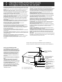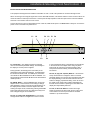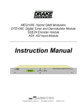
1
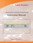
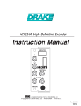
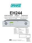
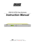
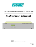
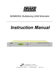
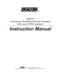
MEQ1000A
Multiplexing Hybrid QAM Modulator
Instruction Manual
MEQ1000A MULTIPLEXING HYBRID QAM MODULATOR
QAM OUPUT
0.00 Mbits/S
ENTER
SELECT
TM is a trademark of R.L. Drake Holdings, LLC
is a registered trademark of R.L. Drake Holdings, LLC
© Copyright 2013 R.L. Drake Holdings, LLC
Part No. 651232700 A
Printed in the U.S.A.
2 Caution Statements
WARNING: TO PREVENT FIRE OR
ELECTRICAL SHOCK, DO NOT
EXPOSE TO RAIN OR MOISTURE
CAUTION
RISK OF ELECTRIC SHOCK
DO NOT OPEN
CAUTION: TO REDUCE THE RISK OF
ELECTRIC SHOCK,
DO NOT REMOVE COVER
NO USER-SERVICEABLE PARTS INSIDE
REFER SERVICING TO QUALIFIED PERSONNEL
A product and cart combination should be moved
with care. Quick stops, excessive force and uneven
surfaces may cause the product and cart combination
to overturn.
The lightning flash with arrow head symbol, within
an equilateral triangle, is intended to alert the user
to the presence of uninsulated “dangerous voltage”
within the product’s enclosure that may be of
sufficient magnitude to constitute a risk of electric
shock to persons.
The exclamation point within an equilateral triangle
is intended to alert the user to the presence of
important operating and maintenance (servicing)
instructions in the literature accompanying
the product.
WARNING:
TO REDUCE THE RISK OF FIRE OR ELECTRIC SHOCK, DO NOT EXPOSE THIS PRODUCT
TO RAIN OR MOISTURE.
DO NOT OPEN THE CABINET; REFER SERVICING TO QUALIFIED PERSONNEL ONLY.
CAUTION:
TO PREVENT ELECTRIC SHOCK, DO NOT USE THIS (POLARIZED) PLUG WITH AN EXTENSION
CORD RECEPTACLE OR OTHER OUTLET UNLESS THE BLADES CAN BE FULLY INSERTED TO
PREVENT BLADE EXPOSURE.
ATTENTION:
POUR PREVENIR LES CHOCS ELECTRIQUES, NE PAS UTILISER CETTE FICHE POLARISEE
AVEC UN PROLONGATEUR, UNE PRISE DE COURANT OU UNE AUTRE SORTIE DE COURANT, SAUF SI LES LAMES PEUVENT ETRE INSEREES A FOND SANS EN LAISSER AUCUNE
PARTIE A DECOUVERT.
The MEQ1000A and its associated input modules have been designed to comply with, and tested to confirm
compliance to the following safety regulations:
ANSI/UL 60065, 7th Edition, dated 06/30/2004, rev. 11/20/2006,
CAN/CSA - C22.2 No. 60065:03 (2006).
Important Safety Instructions 3
Consignes importantes de sécurité 3
1. Read Instructions—All the safety and operating Instructions should be read
before the product is operated.
1a. Lire les directives -Toutes les directives de sécurité et d’utilisation
devraient être lues avant de mettre l’appareil en opération.
2. Retain Instructions—The safety and operating instructions should be
retained for future reference.
2a. Conserver les directives – Les directives de sécurité et d’utilisation
devraient être conservées pour consultation future.
3. Heed Warnings—All warnings on the product and in the operating
instructions should be adhered to.
3a. Tenir compte des avertissements –Tous les avertissements apparaissant
sur l’appareil et dans les consignes d'utilisation devraient être respectés.
4. Follow instructions - All operating and use instructions should be followed.
4a. Suivre les directives - Toutes les directives d’opération et d'utilisation
devraient être suivies.
5. Cleaning—Unplug this product from the wall outlet before cleaning. Do not
use liquid cleaners or aerosol cleansers. Use a damp cloth for cleaning.
5a. Nettoyage – Débrancher l’appareil de la prise électrique murale avant le
nettoyage. Ne pas utiliser de nettoyants liquides ou aérosols. Employer un linge
humide pour le nettoyage.
6. Attachments—Do not use attachments that are not recommended by the
product manufacturer as they may cause hazards.
6a. Fixation – Ne pas utiliser d’autres fixations que celles recommandées par le
manufacturier; elles pourraient être source de dangers.
7. Water and Moisture—Do not use this product near water—for example,
near a bathtub, wash bowl, kitchen sink or laundry tub; in a wet basement; or
near a swimming pool; and the like.
7a. Eau et humidité – Ne pas utiliser cet appareil près de l’eau. Par exemple,
près d'une baignoire, d’un bac de lavage, d'un évier de cuisine ou d'une cuvette
de lessivage; dans un sous-sol humide; ou à proximité d'une piscine; et autres
environnements similaires.
8. Accessories—Do not place this product on an unstable cart, stand, tripod,
bracket, or table. The product may fall, causing serious injury to a child or adult
and serious damage to the product. Use only with a cart, stand, tripod, bracket,
or table recommended by the manufacturer, or sold with the product. Any
mounting of the product should follow the manufacturer's instructions, and
should use a mounting accessory recommended by the manufacturer.
8a. Accessoires – Ne pas installer cet appareil sur un chariot, un socle, un
trépied, un support ou une table instables. L’appareil pourrait tomber, entraînant
des blessures graves à un enfant ou à un adulte, et des dommages importants à
l’appareil. Employer seulement avec un chariot, un socle, un trépied, un support,
ou une table recommandés par le fabricant ou vendu avec l’appareil. Toute
installation de l’appareil devrait être conforme aux directives du manufacturier et
devrait utiliser des accessoires d’installation recommandés par celui-ci.
9. A product and cart combination should be moved with care. Quick stops,
excessive force, and uneven surfaces may cause the product and cart
combination to overturn.
9a. Un chariot supportant l’appareil devrait être déplacé avec précaution. Les
arrêts brusques, la force excessive et les surfaces inégales peuvent renverser le
chariot.
10. Ventilation—Slots and openings in the cabinet are provided for ventilation
and to ensure reliable operation of the product and to protect it from
overheating, and these openings must not be blocked or covered. The
openings should never be blocked by placing the product on a bed, sofa, rug,
or similar surface. This product should not be placed in a built-in installation
such as bookcase or rack unless proper ventilation is provided or the
manufacturer's instructions have been adhered to.
10a. Ventilation – Des fentes et ouvertures dans le châssis sont prévues pour
la ventilation de l’appareil, pour en assurer la fiabilité d’opération et le protéger
contre la surchauffe. Ces ouvertures ne doivent pas être bloquées ou
recouvertes. Ces ouvertures ne devraient jamais être bloquées en plaçant
l’appareil sur un lit, un sofa, une couverture, ou une surface semblable. Cet
appareil ne devrait pas être installé dans un meuble encastré comme une
bibliothèque ou une étagère à moins de lui fournir une ventilation adéquate ou
que l’installation soit conforme aux directives du manufacturier.
11. Power Sources—This product should be operated only from the type of
power source indicated on the marking label. If you are not sure of the type of
power supplied to your home, consult your product dealer or local power
company. For products intended to operate from battery power, or other
sources, refer to the operating instructions.
11a. Sources d’alimentation électrique - Cet appareil devrait être utilisé
seulement avec le type d’alimentation électrique inscrite sur l’étiquette. Si vous
n'êtes pas certain du type d’alimentation électrique fourni à votre maison,
consultez le vendeur de l’appareil ou l’entreprises d'énergie locale. Pour des
appareils alimentés par une batterie ou d'autres sources, se référer aux
consignes d'utilisation.
12. Grounding or Polarization—This product may be equipped with a
polarized alternating-current line plug (a plug having one blade wider than the
other) This plug will fit into the power outlet only one way. This is a safety
feature. If you are unable to insert the plug fully into the outlet, try reversing the
plug. If the plug should still fail to fit, contact your electrician to replace your
obsolete outlet. Do not defeat the safety purpose of the polarized plug.
Alternate Warnings—If this product is equipped with a three-wire grounding-type
plug, a plug having a third (grounding) pin, the plug will only fit into a groundingtype power outlet. This is a safety feature. If you are unable to insert the plug into
the outlet, contact your electrician to replace your obsolete outlet. Do not defeat
the safety purpose of the grounding-type plug.
12a. Mise à la terre ou polarisation - Cet appareil peut être équipé d'une fiche
électrique de courant alternatif polarisée (une fiche ayant une lame plus large
que l'autre). Cette fiche ne s’insérera correctement dans la prise de courant que
d’une seule façon; c'est un dispositif de sécurité. S’il est impossible d’insérer la
fiche entièrement dans la prise de courant, essayer de renverser la fiche. Si la
fiche ne s’insère toujours pas, contacter un électricien pour remplacer la prise
de courant désuète. Ne pas altérer le dispositif de sécurité de la fiche polarisée.
Mise en garde supplémentaire - Si cet appareil est équipé d'une fiche électrique
à trois broches (une fiche ayant une broche de mise à la terre), la fiche
s'insérera seulement dans une prise de courant équipée d’une mise à la terre;
c'est un dispositif de sécurité. S’il est impossible d’insérer la fiche dans la prise
de courant, contacter un électricien pour remplacer la prise de courant désuète.
Ne pas altérer le dispositif de sécurité de la fiche avec mise à la terre.
13. Power-Cord Protection—Power-supply cords should be routed so that they
are not likely to be walked on or pinched by items placed upon or against them,
paying particular attention to cords at plugs, convenience receptacles, and the
point where they exit from the product.
13a. Protection du cordon d’alimentation - Les cordons d’alimentation
devraient être disposés de façon à ce qu’on ne puisse marcher dessus ou qu’ils
soient susceptibles d’être coincés par des articles placés sur ou contre eux. Une
attention particulière doit être portée aux fiches, prises de courant, et aux points
où ils sortent de l’appareil.
14. Outdoor Antenna Grounding—If an outside antenna or cable system Is
connected to the product, be sure the antenna or cable system is grounded so
as to provide some protection against voltage surges and built-up static
charges. Article 810 of the National Electrical Code, ANSI/NFPA 70, provides
information with regard to proper grounding of the mast and supporting
structure, grounding of the lead-in wire to an antenna discharge unit, size of
grounding conductors, location of antenna-discharge unit, connection to
grounding electrodes, and requirements for the grounding electrode.
See Figure A.
14a. Mise à la terre de l’antenne extérieure - Si un système extérieur
d'antenne ou de câble est relié à l’appareil, s’assurer que le système d'antenne
ou de câble est muni d’une mise à la terre afin de fournir une certaine protection
contre les surtensions et les charges d’électricité statique. L'article 810 du code
électrique national, ANSI/NFPA 70, fournit l'information nécessaire en ce qui
concerne la mise à la terre appropriée du mât et de la structure porteuse, la
mise à la terre du câble de connexion à une unité de décharge d’antenne, le
calibre des conducteurs de mise à la terre, la location de l’unité de décharge
d’antenne, le raccordement aux électrodes de mise à la terre et les
spécifications pour les électrodes de mise à la terre.
Voir la figure A.
15. Lightning—For added protection for this product during a lightning storm,
or when it is left unattended and unused for long periods of time, unplug It from
the wall outlet and disconnect the antenna or cable system. This will prevent
damage to the product due to lightning and power-line surges.
15a. Foudre - Pour une protection supplémentaire de cet appareil pendant un
orage électrique, ou quand il est laissé sans surveillance et inutilisé pendant de
longues périodes, le débrancher de la prise électrique murale et déconnecter le
système d'antenne ou de câble. Ceci préviendra les dommages à l’appareil dus
à la foudre et aux surtensions.
16. Power Lines—An outside antenna system should not be located in the
vicinity of overhead power lines, other electric light or power circuits, where it
can fall into such power lines or circuits. When installing an outside antenna
system, extreme care should be taken to keep from touching such power lines
or circuits as contact with them may be fatal.
16a. Lignes électriques - Un système d'antenne extérieur ne devrait pas être
situé à proximité de lignes électriques aériennes ou de tout autre circuit
électrique, où il pourrait tomber sur de tels circuits ou lignes électriques. Lors de
l’installation d’un système d’antenne extérieur, d’extrêmes précautions devraient
être prises afin de prévenir tout contact avec des lignes ou circuits électriques.
Entrer en contact avec de tels circuits ou lignes électriques pourrait être fatal.
17. Overloading—Do not overload wall outlets, extension cords, or integral
convenience receptacles as this can result in a risk of fire or electric shock.
17a. Surcharge – Ne pas surcharger les prises de courant murales, les
rallonges électriques ou les prises de courant intégrées. Un risque d’incendie ou
de choc électrique pourrait résulter d’une telle surcharge.
4
4
Important Safety Instructions (cont.)
Consignes importantes de sécurité
18. Object and Liquid Entry—Never push objects of any kind into this product
through openings as they may touch dangerous voltage points or short-out parts
that could result in a fire or electric shock. Never spill liquid of any kind on the
product.
18a. Insertion d’objet ou de liquide – Ne jamais insérer d’objet par les
ouvertures de cet appareil. Il pourrait toucher des points de voltage dangereux
ou court-circuiter des pièces, ce qui pourrait résulter en incendie ou en choc
électrique. Ne jamais verser de liquide sur l’appareil.
19. Servicing—Do not attempt to service this product yourself as opening or
removing covers may expose you to dangerous voltage or other hazards. Refer
all servicing to qualified service personnel.
19a. Entretien –Ne pas essayer de faire soi-même l’entretien de cet appareil.
En ouvrir ou en retirer les couvercles pourrait vous exposer à des voltages
dangereux ou à d’autres dangers. Confier tout entretien à un personnel de
service qualifié.
20. Damage Requiring Service—Unplug this product from the wall outlet and
refer servicing to qualified service personnel under the following conditions:
a. When the power-supply cord or plug is damaged,
b. If liquid has been spilled, or objects have fallen into the product,
c. If the product has been exposed to rain or water,
d. If the product does not operate normally by following the operating instructions. Adjust only those controls that are covered by the operating
instructions as an improper adjustment of other controls may result in damage
and will often require extensive work by a qualified technician to restore the
product to its normal operation,
e. If the product has been dropped or damaged in anyway, and
f. When the product exhibits a distinct change in performance—this indicates a
need for service.
20a. Dommage exigeant un entretien - Débrancher cet appareil de la prise de
courant électrique et confier l'entretien au personnel de service qualifié dans les
éventualités suivantes:
a. Quand le cordon d’alimentation ou sa fiche sont endommagés,
b. Si des objets sont tombés dans l’appareil, ou si du liquide y a été renversé,
c. Si l’appareil a été exposé à la pluie ou à l'eau,
d. Si l’appareil ne fonctionne pas normalement en suivant les consignes
d'utilisation.
Ajuster seulement les commandes qui sont mentionnées dans le guide
d'opération. Un mauvais ajustement des autres commandes pourrait causer des
dommages à l’appareil et souvent exiger un travail supplémentaire de la part
d’un technicien qualifié pour remettre l’appareil en état normal d’opération.
e. Si l’appareil a été échappé ou endommagé de n’importe quelle façon, et
f. Quand l’appareil montre un changement notable de performance – ceci
indique qu’un entretien est nécessaire.
21. Replacement Parts—When replacement parts are required, be sure the
service technician has used replacement parts specified by the manufacturer
or have the same characteristics as the original part. Unauthorized substitutes
may result in fire, electric shock or other hazards.
21a. Pièces de rechange - Si des pièces de rechange sont nécessaires,
s’assurer que le technicien de service a employé des pièces de rechange
spécifiques du manufacturier ou ayant les mêmes caractéristiques que les
pièces originales. L’utilisation de pièces de rechange non autorisées pourrait
résulter en incendie, choc électrique ou autres dangers.
22. Safety Check—Upon completion of any service or repairs to this product,
ask the service technician to perform safety checks to determine that the
product is in proper operating condition.
22a. Vérification de sécurité – À la suite de toute réparation ou entretien de
cet appareil, demander au technicien de service d'exécuter des vérifications de
sécurité afin de s’assurer que l’appareil est en condition normale de
fonctionnement.
23. Wall or Ceiling Mounting—The product should be mounted to a wall or
ceiling only as recommended by the manufacturer.
23a. Montage au mur ou au plafond - L’appareil ne devrait être monté au mur
ou au plafond qu’uniquement de la façon recommandée par le manufacturier.
24. Heat—The product should be situated away from heat sources such as
radiators, heat registers, stoves, or other products (including amplifiers) that
produce heat.
24a. Chaleur – L’appareil devrait être situé loin de sources de chaleur telles que
des radiateurs, des registres de chaleur, des fourneaux, ou d'autres appareils (y
compris amplificateurs) produisant de la chaleur.
Figure A
Example of antenna grounding as per National Electrical Code, ANSI/NFPA 70
Exemple de mise à la terre d’antenne selon le code électrique national, ANSI/NFPA 70
NOTE TO CATV SYSTEM INSTALLERS:
THIS REMINDER IS PROVIDEO TO CALL THE
CATV SYSTEM INSTALLER'S ATTENTION TO
ARTICLE 820 - 40 OF THE NEC THAT PROVIDES
GUIDELINES FOR PROPER GROUNDING AND,
IN PARTICULAR, SPECIFIES THAT THE CABLE
GROUND SHALL BE C0NNECTED TO THE
GROUNDING SYSTEM OF THE BUILDING, AS
CLOSE TO THE POINT OF CABLE ENTRY AS
PRACTICAL.
NOTE AUX INSTALLATEURS DE SYSTÈME DE
CATV :
CE RAPPEL EST FOURNI POUR PORTER À
L’ATTENTION DES INSTALLATEURS DE
SYSTÈME DE CATV, L'ARTICLE 820 - 40 DU NEC
QUI DONNE DES DIRECTIVES POUR UNE MISE
À LA TERRE APPROPRIÉE ET, EN
PARTICULIER, SPÉCIFIE QUE LE CÂBLE DE
MISE À LA TERRE DEVRAIT ÊTRE RACCORDÉ
AU SYSTÈME DE MISE À LA TERRE DU
BÂTIMENT LE PLUS PRÈS POSSIBLE DE
L’ENTRÉE DU CÂBLE.
ANTENNA LEAD IN WIRE
CÂBLE DE CONNEXION DE
L’ANTENNE
GROUND CLAMP
ANTENNA DISCHARGE UNIT
(NEC SECTION 810-20)
UNITÉ DE DÉCHARCHE
D’ANTENNE
ELECTRIC
SERVICE
EQUIPMENT
NEC
- NATIONAL ELECTRIC CODE
NEC – CODE ÉLECTRIQUE NATIONAL
GROUNDING CONDUCTORS
(NEC SECTION 810-21)
CONDUCTEURS DE MISE À LA
TERRE
GROUND CLAMPS
ATTACHES DE MISE À LA
TERRE
POWER SERVICE GROUNDING
ELECTRODE SYSTEM (NEC
ART 250. PART H)
SYSTÈME DE MISE À LA TERRE
DU BÂTIMENT
Table of Contents /
TABLE OF CONTENTS
2 Caution Statements
3 Important Safety Instructions
5
6 General Description
7 Installation and Mounting / Front Panel Controls
8 Rear Panel Controls and Connections
9 Setup and Programming / Software Flow Chart
12 Setup and Programing (Continued) / Operation
13
14
16
17
18
19
Operating Instructions for Drake Digital Headend Program
DTA/EAS Considerations and Additional Information
CATV Channel Frequencies
Broadcast TV Channel Frequencies
Service / If You Need To Call For Help
Warranty
SPECIFICATIONS
MEQ1000A
Modulation Modes:
Symbol Rate:
FEC:
I/Q Phase Error:
Carrier Suppression:
Channel Amplitude Error:
MER:
MEQ1000A
Output Frequency Range:
Channel Plan:
Frequency Stability:
Maximum Output Level:
Minimum Output Level:
Output Level Accuracy:
Output Impedance:
Spurious Outputs:
Broadband Noise:
Phase Noise:
MEQ1000A
Data Link:
RS232 Input:
RS232 Output:
MEQ1000A
MEQ1000A
Power:
Weight:
Size:
Operating Temperature:
QAM Modulator
16QAM, 32QAM, 64QAM, 128QAM,
256QAM, 512QAM, or 1024QAM.
1 Ms/s to 7 Ms/s.
ITUA (DVB) or ITUB (Digitcipher).
Less than 1 degree.
45 dB.
Less than 1 dB.
Greater than 38 dB with blind equalizer.
Upconverter RF Output
54 MHz to 1002 MHz.
Standard CATV, HRC, IRC, or Broadcast.
± 5 ppm.
+ 61 dBmV minimum, adjustable
downward.
+ 45 dBmV.
± 1 dB.
75 Ohms with return loss better than
14 dB (within output filter passband).
-60 dBc from 40 MHz to 1000 MHz.
Less than -12 dBmV (6 MHz BW @
± 12 MHz).
-101 dBc @ 10 kHz offset.
RS232 Control
2400, 4800, 9600, or 19,200 baud
interface via serial cable.
DB-9 connector for connection to
modem or PC.
DB-9 connector for connection to
other transcoders.
ASI Output
The ASI output provides a copy of the
transport stream that is input to the QAM
modulator.
General
90 - 132 VAC/60 Hz, 35 W maximum.
9.5 pounds.
19” W x 1.75” H x 14.5” D.
0 degrees C to + 50 degrees C.
5
6 General Description
MEQ1000A MULTIPLEXING HYBRID QAM MODULATOR
QAM OUTPUT
0.000 Mbits/S
GENERAL DESCRIPTION
The R.L. Drake model MEQ1000A is a commercial grade
hybrid QAM modulator. The MEQ1000A features plug-in
input modules that include an ATSC/QAM tuner, an ASI
input, an SDI/HD-SDI input, HDMI (non-HDCP), Composite input, Component input, and analog NTSC inputs;
thus the description 'hybrid' is used to describe it. A
multiplexer is built in to combine the transport streams
and input the filtered and groomed transport stream to
the QAM modulator. This manual includes feature examples utilizing the Drake DTD1000 Digital Tuner and
Demodulator Module, and the ASII ASI-Input Module.
Other available input modules include:
SDE24 Dual SD MPEG Encoder
HDE24 High Definiton MPEG Encoder
SDI24A SDI/HD-SDI Input Encoder
SDE24EAS Emergency Alert System Encoder
The MEQ1000A has two input module slots and the outputs interface to the MEQ1000A multiplexer, internally,
where they are MPEG program filtered, multiplexed, and
groomed. Programs, among the total group from input
module A and input module B, may be selected or not
selected by the operator to be sent to the QAM modulator. Each input must contain no more than 20 programs
and a maximum of 20 programs per input may be selected. Also, the total bitrate of the selected programs must
not exceed that of the output QAM channel capacity.
modulated signal. It may be used to convert one off-air ATSC 8VSB signal to a QAM output with rate adjustment. Used in the
processor mode with only one input, the DQT1000 can process
ATSC or CATV QAM inputs. No multiplexing or altering of any
MPEG tables is performed in this mode.
Used in the non-multiplexing mode, the data rate of the incoming signal can be any rate that falls within the specification
range. The output rate can be set to any fixed output rate (equal to or faster than the input rate).
MULTIPLEXING TWO ATSC TRANSPORT STREAMS
Utilizing two DTD1000 input modules, two off-air 19.4 Mbps ATSC
signals (QAM modulated CATV delivered signals could also be
used) can be received and multiplexed to obtain a 38.8 Mbps
256QAM output. Thus two ATSC inputs can be output on a single
6 MHz bandwidth 256 QAM channel.
Another way of combining two ATSC 19.4 Mbps streams is to
receive the first stream using the 8VSB input (DTD1000) and
input the second stream, if available in ASI format, through the
ASII module in the second input slot. Again the two combined
ATSC signals will be modulated at 256QAM in a 6 MHz wide
channel. If it is desired to provide both ATSC signals from two
ASI sources, two ASII modules can be used.
When the MEQ1000A is used as described above, no loss of
picture or sound packets occurs. There is no added compression
of the video or audio streams. Only the necessary control packets
are rewritten to prevent duplication of MPEG2 program numbers
and major and minor channel number assignments in the tables.
Some common applications include: Channel Drop/Add,
cherry picking programs from ASI MPTS inputs, digital
channel processing, or local origination additions.
Using a PC interface, the operator can select the major and minor
program numbers that he desires for each program in the output
multiplex.
The MEQ1000A contains a high performance QAM modulator that can operate in most ITU-A or ITU-B modes up
through 1024QAM. The very low noise, high output, upconverter provides coverage from 54 MHz to 1002 MHz
while maintaining exceptionally low phase noise and
broadband noise. Output level can be selected at a value between + 45 dBmV and + 61 dBmV.
PROGRAM FILTERING
A 'Select Program' function is provided to allow the operator to
select which of the MPEG programs present on the A and B input
streams are to be included in the output multiplex.
The MEQ1000A operates in a fixed output clock mode
and processes null packets when required to maintain the
set fixed clock rate. PCR correction is included.
DIGITAL CHANNEL PROCESSING (One input module)
The DTD1000 input module tunes any 8-VSB or QAM
channel between 54 MHz and 1002 MHz. It is ideal for
digital 'channel processing' applications where a single digital video signal is received, error corrected, clocked at a user determined fixed rate and remodulated on the same or
another RF channel. Applications include cleaning up a
low MER QAM signal received from a CATV source or fiber
link receiver, or shifting the RF frequency of a QAM
PSIP OPTIONS
When operating in the multiplex mode, the MEQ1000A can be set
to process PSIP information from both sources and rewrite tables
containing combined PSIP information, or in cases where the offair
broadcast channels may not be transmitting some or all of the
tables, it can be set to ignore and discard the PSIP tables
completely, or it can be set to generate MGT and VCT tables
without EIT tables. Null packet processing is applied as necessary
to keep the output data rate at the desired setting. PCR
correction is provided. The operator can program desired major
and minor channel numbers for each program in the output
stream.
OUTPUTS - RF and ASI
The 54 to 1000 MHz RF output is always QAM regardless of
whether the input is VSB or QAM. This same filtered stream is
also output via the rear panel ASI output jack.
Installation & Mounting / Front Panel Controls 7
INSTALLATION AND MOUNTING NOTES
This equipment is designed to be installed in a standard 19” rack. A built in fan provides air movement through the unit.
When connecting an incoming RF signal source to two DTD1000 modules, note that the antenna or CATV source must be connected to both the A and B input connectors. These inputs are kept separate in case the inputs need to come from different
antennas or one antenna and one CATV source.
Connect the AC line cord to an appropriate source of 120 volt, 50/60 Hz AC power. The MEQ1000A is always on once the AC
power cord is connected to its power source.
F1
F2
F5
F6
F7
F8
MEQ1000A MULTIPLEXING HYBRID QAM MODULATOR
ENTER
QAM OUTPUT
0.000 Mbits/S
F3
SELECT
F4
F1, LCD Display – This display presents the selected
menu screen and the parameter settings. The backlight in
the display is on when power is applied.
During operation, the S/N (signal to noise ratios) of the
demodulator input signals are displayed. For 8VSB inputs,
the threshold is about 15 dB. For QAM inputs, the threshold is about 23 dB for 64QAM and 27 dB for 256QAM. You
should maintain a S/N several dB above these thresholds for
reliable operation.
F2, ENTER Button – Use the ENTER button to enter the
adjust mode or to save and load a new setting or settings
after adjustment. Hold for 2 seconds until the bottom line of
the display starts to flash to enter the adjust mode. After
entering the adjust mode, momentarily pressing the ENTER
button again will load and save any settings that may have
been changed using the F5 & F6 buttons.
F3 & F4, ◄ (Left) and ► (Right) Buttons – Use the left
and right arrow buttons to navigate from screen to screen
to view a parameter setting. These buttons are operational
in the view mode or the adjust mode. Using only these
buttons will not change any parameter settings. After a
short period of button inactivity, the default display will
be returned.
F5 & F6, ▲ (Up) and ▼ (Down) Buttons – Use the down
and up arrow buttons to change the value of a viewed
parameter setting. The unit must be in the adjust mode with
the display flashing in order for these buttons to become
active for changing a parameter setting. If the unit is not in
the adjust mode, pressing the up button will display the
firmware version number or pressing the down button will
display the output QAM symbol rate.
F7 & F8, ◄ Select ► Buttons - Use the left or right
Select arrow buttons to select which section of the unit to
control. Select one of the input modules or the QAM
modulator / up converter section.
8 Rear Panel Connections
R1
R2
R3
R4
R5
R6
R7
R8
R9
MEQ1000A - This illustration shows the rear of the MEQ1000A.
The ASI connectors are type BNC female.
The ASI input is used to input SCTE-18 data in ASI format for
use with DTAs and in EAS daisy-chaining applications.
R1; RF OUTPUT – This is the high level (61 dBmV), 54 to 1002 MHz, output from the
MEQ1000A upconverter section.
R2; Contact Closure Terminal - Connect these to EAS Receiver Contact Closure
cables to allow the triggering of EAS activation.
R3; ASI Input - This is for receiving EAS and DTA data from a Drake EH24, EH24A,
EH244, EH244-IP or MEQ1000A.
R4; Input Module Slot A.
R5; Input Module Slot B.
R6; ASI Output - This output delivers the same multi-program transport stream in ASI as
is sent to the QAM modulator. When the DTA/EAS mode is Enabled, this ASI output no
longer outputs the same data as the QAM output; it now acts as an ASI Loop, outputting
DTA/EAS data only.
R7; RS232 in - Connection to a PC or modem for use with remote control / monitoring
program or for firmware update download.
R8; RS232 OUT - Loop/Daisychain to another MEQ1000A.
R9; AC Line Cord – For connection to the nominal 120 VAC power source. This unit is
designed for use in countries with 120 VAC power standards but the power supply will
accept an input voltage range of 90 VAC minimum to 260 VAC maximum with a power
line frequency of either 50 or 60 Hz.
Setup and Programming / Software Flow Chart 9
Programming and viewing of the various setup and operating parameters is accomplished using the front panel back lit, two line, sixteen character wide LCD along with the two LEFT and
RIGHT SELECT buttons and the five LEFT, RIGHT, UP, DOWN and ENTER buttons.
The name of the parameter is on the top line of the display and the setting value is on the bottom line. To observe a certain parameter setting without intending to change its value, just use
the LEFT and RIGHT SELECT buttons and the LEFT and RIGHT arrow buttons to navigate
through the menus shown in the software flow chart below.
The current setting for each parameter is shown on the bottom line of the display.
Note that depending upon certain settings, some screens are not needed and will be skipped.
To make a change in the displayed parameter and its setting and if this is the initial setup, you
will want to enter the ‘adjust’ mode. To do this, press the ENTER button that is located in the
center of the four arrow buttons and hold in for several seconds until the display begins to flash.
After you are in the adjust mode (bottom line of screen flashing) use the left and right arrows to
navigate among screens and use the up and down arrows to change the parameter setting.
When ENTER is pressed, the new settings will be loaded and stored and the unit will exit the
‘adjust’ mode. You may wish to not press ENTER until you have gone through all screens and
settings and then press ENTER to save and load all changes in one step OR you can store just
one or several parameters at a time and reenter adjust mode to set the next.
Either method is acceptable.
10 Setup and Programming (Continued)
This section provides additional details regarding the
selectable items shown in the ‘adjust’ mode on the
Software Flow Chart on page 8.
Choose the SELECT PROGRAMS setting to allow the
operator to pick which programs from the A and B inputs are
to be included in the output multiplex.
SETUP: MEQ1000
(For Specific EAS and DTA Settings, Refer to Page 14)
NOTE: At this point you may proceed through the remaining
menus, below, before pressing the ENTER button to load the
selected data OR you may press ENTER now and then come
back to the rest of the menus. In any case, when the ENTER
button is pressed, one of the following two actions will occur:
UNIT ID: Select the desired unit identification number when
connecting the 'RS232 IN' connector to a PC or modem for
remote control using 'Drake Remote Control Software'.
Numbers 1 thru 63 may be used. If zero (0) is selected, the
PC will ignore the unit.
RS232 BAUD RATE: This setting determines the baud
rate at which the MEQ1000 communicates with the remote
PC. Settings available are 2400, 4800, 9600 and 19,200.
All units 'daisy chained' to the remote PC or modem must
be set to the same baud rate.
MULTIPLEX: This setting determines whether the Input
Module Slot A input is to be multiplexed with a second
input (if installed). Select Input Module Slot A to activate the
A Input Module only. Select Input Module Slot B to activate
the B input module only. To turn on the multiplex function
select ENABLED. If either A or B Input module is selected,
the next menu will be the QAM MODE menu. You may skip
to that paragraph, below.
INPUT B OFFSET: When the Input Module Slot B or ASI
input has been installed and selected in the MULTIPLEX
menu, this menu will be present. Because the two incoming
transport streams are likely to have overlapping use of
MPEG program numbers, the MEQ1000 will pass the
program numbers from input A unchanged and an offset,
equal to the value chosen in this menu, will be added to the
program number of programs from the second input. This
same offset value will also be added to the minor channel
number in the VCT table for programs from the second
input source. Usually an offset of 10 will be adequate but if
you know there are programs in the signal input to input A
using program numbers above 10, a higher offset may be
required. Values between 10 and 90, in increments of 10,
are available for selection. When it is known that there is
no overlap between input A and input B stream program
numbers, a 0 offset setting can be used. Be cautious if this
is the selection that is chosen.
MPEG PROGRAMS: This menu provides selections to
determine which programs are multiplexed to form the new
multiprogram transport stream output that will be supplied
to the QAM modulator section. Choose the SELECT ALL
PROGS setting to multiplex all programs from inputs A
and B up to 20 programs maximum. If more than 20 exist,
you must use SELECT PROGRAMS and only select 20
maximum.
It is the operator's responsibility to be sure that the total
data rate of these programs does not exceed the maximum
data rate for the output QAM mode that will be used,
typically 26.98 Mbps for 64QAM or 38.8 Mbps for 256QAM
in ITUB modes. If the sum of input bitrates would exceed
this amount, or if more than 20 programs are present,
some programs will have to be dropped from the list of
selected programs.
A) If SELECT ALL PROGS has been selected, the MEQ1000A
will now read PAT tables from the two input streams and discover which MPEG programs are defined. If you wish to view
the MPEG program numbers of programs that were found, follow the procedure below:
VIEWING MPEG PROGRAM NUMBERS
In order to see the MPEG program numbers of incoming streams, the following procedure can be followed:
1) Press the ENTER button for 2 seconds to enter program mode. Release button. Display will be flashing.
2) Press the ENTER key again and hold. By continuing
to hold in the ENTER button, the following display will
be slowed down so that program numbers can be read
as they scroll by.
3) A screen will be displayed that indicates:
PMT PROG A xxxx or PMT PROG B xxxx.
4) The xxxx field will be a number that corresponds to
the MPEG program number of a program found in the
PMT table for the indicated (A or B) input. As the button
is held, all entries for input A will scroll past and then
entries for input B will scroll past.
5) Release button and if necessary repeat steps 1 - 4.
B) If SELECT PROGRAMS was chosen, the unit will read
the PAT tables from both inputs and then display:
MPEG PROG XXXXX: (XXXXX is a number from 00001 to
65535) on the top line of the display. Using the right and
left arrow keys, you can scroll through all 65535 possible
program numbers.
Don't be alarmed by the large number of possibilities
because if the arrow key is held down, the scrolling will
speed up so all 65535 possible numbers can be scanned in a
short time - any time an entry is found at a given program
number, the scrolling will slow down to give the operator time
to see it and stop scrolling, if desired. Usually, all programs
are known to be numbered between 01 and 20.
For each MPEG program number, displayed on the top line,
the bottom line, on the right, will indicate A, B, AB, or nothing.
This will indicate that the program number on the top line was
found in input A or B or AB for both or not in either one if
blank.
To select programs to be included in the output multiplex,
use the up and down arrow keys to select NOT SELECTED,
INPUT A, INPUT B, or INPUT A+B. If NOT SELECTED is
used, then this program number will not be present in the
output and any programs with this program number that are
present in the A or B inputs will be filtered out. If INPUT A is
selected, the A input program only is used.
Setup and Programming (Continued) 11
If INPUT B is selected, the B program is used and A filtered
out. If INPUT A+B is chosen, then both are accepted if
present.
Note: It is OK to use this menu to set up desired program
selections 'off line'. That is, with no actual input at the
present time. Programs may be selected that may not
currently be in the input stream but are desired at some
future time.
Note: It is possible to select both programs with the same
program number - one from A and one from B as long as
the INPUT B offset is set so that the B program number plus
the offset amount does not duplicate a program number
from the A input. The offset is not included in the MPEG
program number display being discussed above but the
offset will be added to all MPEG program numbers from the
B input when they are added to the output multiplex.
PSIP: This menu provides a choice of how the unit
organizes the PSIP information from two ATSC streams that
are being multiplexed.
In the ENABLED setting, information from the MGT and
VCT tables from both signals will be used to build a new
table for the combined output signal. Both input streams
must have these tables present in order for the unit to be
able to perform this operation. EIT tables will be processed
so as to provide program information, if present, for the next
12 hours. This selection is the only one that passes EIT
table program information to the multiplexed output signal.
RRT and STT tables from Demod A are passed through.
If the broadcast station is not transmitting complete MGT
and VCT tables, the ENABLED selection cannot be used. In
this situation, DISABLED may be selected. In DISABLED
mode, the unit does not process or output any MGT, VCT, or
EIT tables. This can be a fine solution for cable systems
that use set top boxes which operate from their own system
channel map and have no need for these tables. MPEG
program information is still processed. Some retail consumer
QAM set tops operate perfectly in this mode and
others may not.
The third option is the BASIC MGT, VCT choice. When this
selection is made, the DQT1000 or MQM1000 will build its
own MGT and VCT tables from the incoming streams even
if one or both of the streams do not contain these tables.
This solution should satisfy all types of set top boxes but
will not provide any EIT table program guide information.
The STT and RRT tables from the source are passed
through unchanged in the ENABLED mode and filtered out
in the other modes.
VCT TABLE: This menu is only available when ENABLED
or BASIC MGT, VCT has been selected in the previous
PSIP menu. You may select the TVCT - TV channel table or
CVCT table for CATV. Usually the TVCT choice must be
selected for ATSC input signals.
MAJOR CHANNEL: This menu is not available if PSIP is
disabled. This setting will determine how a channel number
is displayed on a consumer TV if the TV is tuning the output
of the MEQ1000A without a cable box.
When ORIGINAL is selected, the major channel number
indicated in the output tables will be that sent by the original
broadcaster. If OUTPUT CHANNEL is selected, the major
channel number will be set to the channel number of the
MEQ1000A RF output channel. When a cable box is used, it
usually does not require or use this information.
Minor channel numbers are the same as those input via
module A and as input via module B with the offset added to
the B side programs.
When USER DEFINED is selected and the remote control
software is used to allow programming via a PC, then the
MPEG program number and the major and minor virtual
channel numbers may be set to whatever number the
operator chooses providing total flexibility. These numbers
cannot be programmed with the front panel buttons but only
via a PC and the RS232 interface of the MEQ1000A.
It is up to the operator to insure that no duplications are
made when using this mode.
QAM MODE: This menu allows the user to set the modulation
type for the output. Choices range from 16-QAM
through 256-QAM. 'A' suffixes indicate DVB compliant FEC
and the 'B' suffixes indicate DigiCipher II FEC encoding.
Note that when using the MEQ1000A in the multiplex mode,
the output QAM mode usually must be 256-QAM. For CATV
systems using DigiCipher II, select the QAM-256B mode.
For DISH Network QAM distribution or other DVB systems
using DVB set tops, choose the QAM-256A mode.
When used for a single input processing function, choose
the output mode accordingly from any of the available
options that will provide a high enough data rate.
GRAY ENCODING: This menu is only available when QAM
modes QAM-16A through QAM-1024A, are selected. The
choices are DVB and DAVIC. Gray Encoding is normally not
used for video data.
QAM SYMRATE: Preset or Manual: If PRESET is
selected, the symbol rate will be automatically set to the
‘normal’ rate based on the QAM mode that is selected and
assuming a 6 MHz wide QAM channel. If MANUAL is
selected, pressing the right or left arrow buttons will allow
selection of symrates from 1.000 thru 7.000 MSym/Sec
using the up and down arrow buttons.
QAM SYMRATE: This menu allows selection of the output
QAM baudrate or symbol rate. Set as required by the set
top box. When multiplexing two ATSC input signals, in
DigiCipher II, 256-QAM CATV systems, this is usually
5.3606 Ms/s. In DVB systems, the rate would be 5.264
Ms/s. In any case, the rate must be high enough to provide
a data bitrate of at least 38.81 Mbps (do not confuse this
with the symbol rate). If the set top box requires a fixed
higher rate, this may be manually set.
12 Setup and Programming (Continued) / Operation
INTERLEAVER: Sets the QAM modulator interleaver. Choose
among the available selections based upon your system / set top
box requirements. For typical 256-QAM. DigiCipher II CATV
systems, I128, J1 is the most commonly used interleave setting but
many other choices are available. This menu does not appear in
the adjust mode if the QAM mode is A (DVB) as there is only one
choice in the DVB standard. When not in adjust mode, this screen
will display the setting in QAM - A modes as well.
OUTPUT FORMAT: For normal operation, select NORMAL. For
system level set up, choose CW to provide a CW carrier at the
center frequency of the output channel for use in leveling a system
when a QAM power meter is not available. To disable all RF output,
select STANDBY. In the CW mode, the CW carrier can be
measured on a spectrum analyzer without a need to apply a
bandwidth correction or it can be measured with an analog meter
tuned to channel center. The CW power measured will equal the
channel QAM power when the modulator is returned to NORMAL
output mode. Usually QAM signals are set 5 dB to 10 dB
below analog NTSC channels when balancing a system. The
PRBS modes provide a pseudo random binary sequence output
test signal for use in laboratory testing.
OUTPUT CHANMAP, OUTPUT CHANNEL: Select the desired EIA
CATV channel output using these two menus.
RF OUT: Select the desired RF output signal level. The available
range is between 45 dBmV and 62 dBmV, selectable in 0.5 dB
steps. The output accuracy is ± 1 dB.
SETUP: SDE24
SELECT: The LEFT and RIGHT buttons allow the user to scroll
through the encoder numbers for each encoder installed in the
MEQ1000A as well as the MEQ1000A itself. Use the LEFT and
RIGHT buttons to select the encoder to be programmed.
OPERATION - MULTIPLEXING TWO ATSC INPUTS
To use the DTD1000, SDE24 and/or the ASII modules to multiplex
two ATSC inputs, proceed as follows:
1) Connect the off-air antenna, CATV feed, or audio and video
(SDE24) or ASI feed, to the INPUT A and INPUT B inputs of the
MEQ1000A. If using two RF inputs the two input connectors are
available in case the two RF signals must come from different
antennas or if one signal is coming from a cable system, etc. If
using a common antenna, use a good quality two way splitter to
split the antenna and feed each input.
2) Plug the power cord from the unit into the power source.
3) Follow the instructions in the programming section above to
set the channel map and channel number for both INPUT
MODULE A and INPUT MODULE B.
4) Set the QAM SYMRATE to PRESET.
5) Set the MULTIPLEX setting ENABLED
6) Set the INPUT B OFFSET to 10. Read details in programming
section to determine if you need another value.
7) Select the desired MPEG programs. (See the previous
section for details.)
8) In the PSIP menu, select BASIC MGT VCT for now, this may
be changed later. See programming section for detail.
9) In the VCT TABLE menu, select TVCT.
10) In the MAJOR CHANNEL menu, select OUTPUT CHANNEL.
This may be changed later.
11) From the QAM MODE menu, set the QAM modulator to
QAM-256B for use in a DigiCipher II environment. If DVB, use
QAM-256A instead.
VIDEO: This menu entry allows the user to select between SVIDEO
and COMPOSITE video input for each selected encoder.
FORMAT: Either MPEG2 or MPEG4 H.264 may be selected as the
output format for the selected encoder using this menu item.
Encoder 2 on a given SDE24 has no option. It is forced to MPEG2.
RESOLUTION: The resolution of the video output of each encoder
may be selected from this menu item. The choices range from 720
x 480 thru 353 x 240 as shown on the software flow chart on page
9.
BRIGHTNESS, CONTRAST, SATURATION and HUE: These
menu items allow the user to assign each of these parameters of
the output video values from 0 to 255.
MAX AUDIO IN: This menu entry allows the user to set the
maximum audio input which may be input to the selected encoder.
The choices are 1 Vrms or 2 V rms.
AUDIO GAIN: The audio output level can be chosen from this
menu item by selection of the appropriate gain. The values range
from + 15 dB to - 15 dB. Audio output can also be completely
eliminated using the ‘MUTE’ selection.
AUDIO ENCODER: The SDE24 includes audio encoders for Dolby
Digital Stereo commercial encoding (AC3) or MPEG1 Layer 2 audio
encoding (MP2). In the USA, the majority of applications will use
AC3 but if your network is using Annex A (DVB) set top boxes, they
may require the MPEG audio selection. Some TVs and set top
boxes will decode either mode but be sure to set the encoder to the
mode used by other programming on your system to insure
complete compatibility. The AUDIO ENCODE(R) menu allows you
to select either AC3 or MP2. Use the up/dn arrow keys to toggle
between the two settings.
12) In the QAM SYMRATE menu, select PRESET.
13) Set the INTERLEAVER to I128,J1 if in a DigiCipher II
environment. There is no interleaver menu when the QAM
mode is set to A (DVB).
14) Set the OUTPUT FORMAT to NORMAL.
15) Set the OUTPUT CHANMAP and OUTPUT CHANNEL to
the desired EIA CATV output channel.
If the second program is being input to a ASII Module via the ASI
input instead of a DTD1000, the same steps apply except that
there will be no parameters to set for the ASII MODULE.
SET TOP BOX MAPPING
When setting up a program map for your set top boxes to include
off-air channels that are multiplexed by the MEQ1000A be sure to
inform the programmer that the MPEG program numbers for the
programs coming in through INPUT MODULE B or ASI B have
been offset by the amount selected in the INPUT B OFFSET
menu. As an example: If input A is providing a channel with
MPEG programs 1 and 2 in the stream and input B is providing a
channel with MPEG programs 1, 2, 3, 4, and 5 in the stream, and
the INPUT B OFFSET is set to 10, then the new output signal will
contain MPEG programs with program numbers of 1, 2, 11, 12,
13, 14, and 15. If the set top is not looking for the right program
number, you will not receive any video!
Operating Instructions 13
(from Drake Digital Headend Control Program)
Operating Instructions - From Drake Digital Headend
Control Program
1) Confirm that all connections to the MEQ1000A and its
installed encoder modules have been made as described
previously. Connect a serial cable from the RS232 IN
connector on the MEQ1000A to the serial port on the PC. (This
discussion assumes that the Headend Control Program has
already been installed on the PC as per the instructions
supplied with the software.)
2) Activate the software. You
should see a screen similar to
FIGURE 1 at right.
3) Click on the ‘Setup New
Headend’ button. This will
bring up the screen shown in
FIGURE 2. Type in the name
of the headend in the
‘HeadEnd Name’ field. In this
case we have typed in
MEQ1000A. Then select the
‘PC Baudrate’ and ‘Using
Port’. If you intend to use a
modem instead of a direct
connection, make that
selection using the ‘Connect
via:’ radio buttons, and type in
the phone number of the
desired modem in the ‘Number
to dial’ window. Then click
‘OK’.
Figure 1
6) Click on the ‘Set Major/Minor Channel Numbers’ button.
You will be presented with a screen shown in FIGURE 5.
7) This screen allows
the user to reasign
MPEG numbers as
well as new major and
minor channel
numbers.
4) You will be presented with
Figure 2
a screen similar to the one
shown on FIGURE 3. Click on the MEQ1000A tab, and click
on the box representing the MEQ1000A unit ID of the unit you
are programming. In this example we selected Unit ID #1.
Then click on the ‘View Edit” button.
Select MEQ1000A Unit ID
you choose to
program. In this
case, 'Input A'
contains an SDE24
which contains two
encoders. Select
radio button '1' and
program each
parameter to the
desired value.
Select radio button
Figure 4
2 and set each parameter to the desired value. Select in turn, 'Input B', 'Mux Setup
and 'Output' and set each parameter as described previously.
Note that if the value of the parameter selected in the left column
differs from the value of that parameter in the right column, that
value will appear in red.
MEQ1000A Tab
8) Once the selections
have been
made, click on the
‘Download to
MEQ1000’ button.
This will transfer all
selections on this
screen as well as all
selections made on
Figure 5
the previous screens
to the MEQ1000A and
its installed modules.
Close this screen by clicking on the ‘X’ in the upper right
hand corner of the screen.
9) You will note that all of the items in the right hand columns
in the 'Input A', 'Input B', 'Mux Setup' and 'Output Encoders',
screens are now black and agree with the selections made in
the left hand columns.
10) Additional information on the operation of the Drake
Digital Headend Control Program can be found in the
instructions included on the program CD.
View / Edit Button
Figure 3
This will bring up the screen shown in FIGURE 4. Click on
the Transcoder box and select the transcoder number you
wish to program. In this case we have selected Transcoder
1. Then select 'Input A' and select the number of the encoder
14 DTA/EAS Considerations and Additional Information
DTA and EAS (EMERGENCY ALERT SYSTEM) CONSIDERATIONS
Any headend using DTAs or EAS (Emergency Alert System) that includes the MEQ1000A must be setup with one EH24A / EH244 /
EH244-IP being the “Master” device and the MEQ1000A and all other additional Drake Headend Products (EH24A / EH244 /
EH244-IP / other additional MEQ1000A) being “Slave” devices.
DTA/EAS CONTROL: The DTA control is used when MEQ1000As are used to supply the QAM signals to DTA set top boxes. It
allows for an ASI stream, generated by a PC to be input to the headend’s Master unit. This control allows for generating
a transport stream that provides a virtual channel map to the DTAs (Known as SCTE 65 tables), and/or provides code updated
to the DTA’s (in a format known as DSM-CC) so that they can be updated through the QAM channel transport stream. The
choices are DISABLED, MASTER (SCTE-18), and SLAVE.
DTA MODE: This menu choice allows the user to activate or deactivate DTA mode. The choices are ENABLE and DISABLE. This
option will only be available when SLAVE is selected under DTA/EAS CONTROL menu.
If DTA MODE is ENABLED, then an ASII module must be present in the Master EH24A / EH244 / EH244-IP to receive
the ASI stream from your PC. Whether it is plugged into Module 5 or Module 6 slot depends on whether the SDE24EAS is
also required in the system or not.
All units at the headend are then daisy-chained through ASI connections.
The Master unit’s ASI OUTPUT connector goes to the ASI INPUT connector of the ASII module in the first Slave unit.
The ASI LOOP output connector of the ASII module in the first Slave unit goes to the ASI INPUT connector of the ASI
module in the next Slave unit.
These ASI LOOPs continue through all Slave units (MEQ1000As, EH24As, EH244s, and EH244-IPs) at the headend.
There can be standard SDE24s in some or all of the remaining slots of the Master unit. If they are wanted to be sent out
on the ASI output of the Master unit, these streams can be picked up from the ASI LOOP output connector of the ASII
module of the last Slave unit in the chain.
VERY IMPORTANT: When the SDE24EAS is used in slot 6 of the Master unit, both encoders in the SDE24EAS
must be set to the lowest encoding bitrate of any other SDE24 in the entire system. This is the only way to make
sure that when the SDE24EAS’ stream replaces the original streams that it will still fit into all the QAM channels.
EAS MODE: EAS Control is provided by 1 of 2 methods:
Method 1 - By using the SDE24EAS module in a “Master” EAS unit (EH24A / EH244 / EH244-IP, but not the MEQ1000A)
as mentioned above. This module has only a single composite input instead of the 2 inputs of a standard SDE24. It is fed
by an external EAS Controller source, that then is encoded by both encoders in the SDE24EAS. When EAS is activated,
the transport stream generated by the SDE24EAS is routed internally in the Master unit and replaces the transport
streams coming from the other plugged in SDE24s. This way all MPEG programs coming out of the Master unit have the
EAS video and audio on them. Note that when using this method only one SDE24EAS is required per headend, and is
placed into the Module 6 slot on the rear of the Master EH24A / EH244 / EH244-IP. The MEQ1000A will need to be
placed in the SLAVE setting.
Method 2 - By using the newer digital standard for EAS (known as SCTE 18). In this mode, rather than each MPEG
program being replaced by the EAS video, instead when the EAS is activated, a table is inserted into the transport
stream. This table tells any SCTE 18 capable unit which RF channel to switch to and which MPEG program number to begin decoding. The receiving unit then switches to that program to display the EAS video and audio. When the EAS is deactivated, the receiving unit returns to its original channel.
For Instructions on how to set EAS parameters (including: EAS MODE, EAS RF CHANNEL, EAS MODULATION, EAS MPEG
PROGRAM #, EAS MAJOR CHANNEL, and EAS MINOR CHANNEL), please see instruction manual for the Drake Product
being used as the EAS MASTER UNIT in your headend (EH24A / EH244 / EH244-IP).
ADDITIONAL CONSIDERATIONS
STANDBY MODE
The MEQ1000A has a standby output mode which turns off the RF output. This can be used when it is desirable to temporarily disable the output without unplugging the AC line cord. Select STANDBY in the OUTPUT FORMAT menu.
OVER TEMPERATURE SENSOR
Temperature monitoring is built into these products. If the ventilation slots or fan output opening are blocked or the fan should stop,
overheating can occur. If this condition is detected, the default LCD message will change to OVER TEMP. If this occurs, the problem should be corrected as soon as possible. The unit will remain operational but the ventilation must be restored to prevent premature part failures due to overheating.
Additional Information (Continued) 15
STATUS DISPLAYS
When the units are not in the adjust/program mode, status displays are shown. These vary by input module:
DTD1000 Digital Tuner and Demodulator Module - shows DEMOD SNRs.
ASII ASI Input Module - shows ASI data presence.
Pushing the UP arrow button will cause the firmware version number to display.
Pressing the DOWN arrow will cause the percentage of buffer capacity that is currently in use on the left side of the display and the
maximum percentage of buffer capacity that has occurred since the unit was last programmed on the right side, for the QAM output
selected.
REMOTE CONTROL AND MONITORING
The MEQ1000A may be used with the 'Drake Digital Headend Remote Control Software' program to allow remote monitoring or control.
Only version 2.10.0 or newer is compatible with the MEQ1000A. If an SDE24 module is installed the Drake Digital Headend Remote
Control Software version must be version 3.1.2 or above.
Connect the RS232 cable coming from the PC or modem to the RS232 IN DB9 rear panel connector.
Assign a UNIT ID (1 to 63) to use the remote program. Leave at, or set to, 0 if no remote access is desired.
Set the RS232 BAUD RATE to match the PC setting.
If you are familiar with the program, operation will be clear. If not familiar with it, see further instructions in the insert provided with the
CD-ROM or stored on the CD-ROM.
The MEQ1000A may also be used with the SCTeci to provide webpage control over a network using an Ethernet connection to the
SCTeci. For control of the MEQ1000A, the SCTeci must have version 5.0 or newer firmware.
16 CATV Channel Frequencies
TABLE 1: CATV
CABLE TV CHANNELS
CABLE TV CHANNELS
CABLE TV CHANNELS
Channel
Number
Center of
Channel
Channel
Number
Center of
Channel
Channel
Number
EIA/NCTA
Numeric
Equivalent
Frequency
in MHz
EIA/NCTA
Numeric
Equivalent
Frequency
in MHz
41
42
43
44
45
46
47
48
49
50
51
52
53
54
55
56
57
58
59
60
61
62
63
64
65
66
67
68
69
70
71
72
73
74
75
76
77
78
79
80
81
82
83
84
85
327
333
339
345
351
357
363
369
375
381
387
393
399
405
411
417
423
429
435
441
447
453
459
465
471
477
483
489
495
501
507
513
519
525
531
537
543
549
555
561
567
573
579
585
591
2
3
4
5
6
95
96
97
98
99
14
15
16
17
18
19
20
21
22
7
8
9
10
11
12
13
23
24
25
26
27
28
29
30
31
32
33
34
35
36
37
38
39
40
57
63
69
79
85
93
99
105
111
117
123
129
135
141
147
153
159
165
171
177
183
189
195
201
207
213
219
225
231
237
243
249
255
261
267
273
279
285
291
297
303
309
315
321
CABLE TV CHANNELS
Center of
Channel
Channel
Number
Center of
Channel
EIA/NCTA
Numeric
Equivalent
Frequency
in MHz
EIA/NCTA
Numeric
Equivalent
Frequency
in MHz
86
87
88
89
90
91
92
93
94
100
101
102
103
104
105
106
107
108
109
110
111
112
113
114
115
116
117
118
119
120
121
122
123
124
125
126
127
128
129
130
131
132
133
134
135
597
603
609
615
621
627
633
639
645
651
657
663
669
675
681
687
693
699
705
711
717
723
729
735
741
747
753
759
765
771
777
783
789
795
801
807
813
819
825
831
837
843
849
855
861
136
137
138
139
140
141
142
143
144
145
146
147
148
149
150
151
152
153
154
155
156
157
158
867
873
879
885
891
897
903
909
915
921
927
933
939
945
951
957
963
969
975
981
987
993
999
Broadcast TV Channel Frequencies 17
TABLE 2: BC TV
VHF BROADCAST CHANNELS
Channel
Number
2
3
4
5
6
7
8
9
10
11
12
13
Center of Channel
Frequency (MHz)
57
63
69
79
85
177
183
189
195
201
207
213
UHF BROADCAST CHANNELS
Channel
Number
14
15
16
17
18
19
20
21
22
23
24
25
26
27
28
29
30
31
32
33
34
35
36
37
38
39
40
41
42
43
44
45
46
47
48
49
50
51
52
53
54
55
56
57
58
59
60
61
62
63
64
65
66
67
68
69
Center of Channel
Frequency (MHz)
473
479
485
491
497
503
509
515
521
527
533
539
545
551
557
563
569
575
581
587
593
599
605
611
617
623
629
635
641
647
653
659
665
671
677
683
689
695
701
707
713
719
725
731
737
743
749
755
761
767
773
779
785
791
797
803
18 Service / If You Need to Call for Help
SERVICE INFORMATION
A Return Material Authorization (RMA) Number is required on ALL PRODUCT RETURNS (regardless if product is being returned for repair or credit). Product received at the factory without a RMA Number will be returned to sender.
RMA numbers must be used when returning product for credit or repair. Use of RMA numbers will ensure efficient processing. When returning product to R.L. Drake Holdings, LLC., please follow the simple steps below (in the order that they appear).
SERVICE REPAIRS ONLY
CREDIT RETURNS ONLY
1. Contact R.L. Drake Holdings, LLC.’s Service Department
in one of three ways:
1. Contact R.L. Drake Holdings, LLC.’s Service Department
in one of three ways:
A. Phone: 937-746-6990
B. Email: [email protected]
C. Fax: 937-806-1576
A. Phone: 937-746-6990
B. Email: [email protected]
C. Fax: 937-746-6990
2. Request from Service a copy of the Product Return Authorization Form.
2. Request from Service a copy of the Product Return Authorization Form.
3. Complete the Product Return Auhtorization Form fully.
3. Complete the Product Return Authorization Form fully.
4. Return the completed Product Return Authorization Form
to the Drake Service Department using one of the contact
methods listed in Step 1.
4. Return the completed Product Return Authorization Form
to the Drake Service Department using one of the contact
methods listed in Step 1.
5. After completing Steps 1 through 4, a RMA Number will
be assigned to you.
5. After completing Steps 1 through 4, a RMA Number will
be assigned to you.
6. Securely pack the product and mark the box with your
RMA Number. If shipping multiple boxes, all boxes must
be marked with the RMA Number. Place the RMA Number near your return address in large, bold print (approx.
2” in height).
6. Securely pack the product in its original undamaged
box (returning the product without its original packaging
in good new condition may cause the incursion of additional fees). Pack this box within another shipping container or box. Mark the shipping box or container with
your RMA Number. Place the RMA Numbers near your
return address in large, bold print (approx. 2” in height).
7. Ship your SERVICE REPAIR ONLY return to:
R.L. Drake Holdings, LLC.
Attn: Product Service Returns
9900 Springboro Pike
Miamisburg, OH 45342
7. Ship your CREDIT RETURNS ONLY return to:
R.L. Drake Holdings, LLC.
Attn: Product Credit Returns
One Jake Brown Road
Old Bridge, NJ 08857
NOTE: All Credit Returns are subject to a
15% Restock Fee
NOTE: All shipments are to be PRE-PAID by the sender. NO COD’s will be accepted.
IF YOU NEED TECHNICAL HELP
Call our Customer Service/Technical Support line at +1 (937) 746-6990 between 8:00 A.M. and 4:00 P.M. Eastern Standard
Time, weekdays. Please have the unit’s serial number available. We will also need to know the specifics of any other equipment connected to the unit. When calling, please have the unit up and running, near the phone if possible.
Our technician(s) will likely ask certain questions to aid in diagnosis of the problem. Also, have a voltmeter handy, if possible.
DRAKE also provides technical assistance by Email: [email protected] or by Fax: (937) 806-1576.
Many of the products that are sent to us for repair are in perfect working order when we receive them. For these units, there
is a standard checkout fee that you will be charged. Please perform whatever steps are applicable from the installation sections of the Instruction Manual before calling or writing - this could save unnecessary phone charges. Please do not return
the unit without contacting DRAKE Service first; it is preferred to help troubleshoot the problem over the phone (or by Email)
first, saving you both time and money.
Warranty 19
Three Year Limited Warranty
R.L. DRAKE HOLDINGS LLC warrants to the original purchaser this product shall be free from defects in material
or workmanship for three (3) years from the date of original purchase.
During the warranty period R.L. DRAKE HOLDINGS LLC or an authorized Drake service facility will provide,
free of charge, both parts and labor necessary to correct defects in material and workmanship. At its option, R.L.
DRAKE HOLDINGS LLC may replace a defective unit.
To obtain such a warranty service, the original purchaser must:
1. Retain invoice or original proof of purchase to establish the start of the warranty period.
2. Notify R.L. DRAKE HOLDINGS LLC or the nearest authorized service facility, as soon as possible after
discovery of a possible defect, of:
a) the model and serial number,
b) the identity of the seller and the approximate date of purchase; and
c) A detailed description of the problem, including details on the electrical connection to associated
equipment and the list of such equipment.
3. Deliver the product to R.L. DRAKE HOLDINGS LLC or the nearest authorized service facility, or ship
the same in its original container or equivalent, fully insured and shipping charges prepaid.
Correct maintenance, repair, and use are important to obtain proper performance from this product. Therefore
carefully read the Instruction Manual. This warranty does not apply to any defect that R.L. DRAKE HOLDINGS
LLC determines is due to:
1. Improper maintenance or repair, including the installation of parts or accessories that do not conform
to the quality and specifications of the original parts.
2. Misuse, abuse, neglect or improper installation.
3. Accidental or intentional damage.
All implied warranties, if any, including warranties of merchantability and fitness for a particular purpose, terminate
three (3) years from the date of the original purchase.
The foregoing constitutes R.L. DRAKE HOLDINGS LLC'S entire obligation with respect to this product, and the
original purchaser shall have no other remedy and no claim for incidental or consequential damages, losses or
expenses. Some states do not allow limitations on how long an implied warranty lasts or do not allow the exclusions
or limitation of incidental or consequential damages, so the above limitation and exclusion may not apply to you.
This warranty gives you specific legal rights and you may also have other rights which vary from state to state.
This warranty shall be construed under the laws of Ohio.
For Service, contact:
R.L. DRAKE HOLDINGS LLC
9900 Springboro Pike
Miamisburg, Ohio 45342. USA
Customer Service and Parts Telephone: +1 (937) 746-6990
Telefax: +1 (937) 806-1576
Web Site: http://www.rldrake.com
R.L. Drake Holdings, LLC
9900 Spingboro Pike
Miamisburg, OH 45342
Customer Service and Parts Telephone: +1 (937) 746-6990
Telefax: +1 (937) 806-1576
www.rldrake.com