1
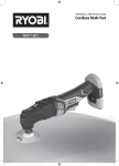
LLCDI1802 GB FR DE ES IT NL PT DK SE FI NO RU PL CZ HU RO LV LT EE HR SI SK GR TR 18 VOLT COMPACT HAMMER DRILL DRIVER PERCEUSE/VISSEUSE COMPACTE À PERCUSSION 18 VOLTS 18 VOLT KOMPAKT SCHLAGBOHRSCHRAUBER ROTOMARTILLO/TALADRO/DESTORNILLADOR DE 18 VOLT TRAPANO A PERCUSSIONE COMPATTO DA 18 VOLT 18 VOLT COMPACTE HAMERBOORMACHINE MARTELO PERFURADOR COMPACTO DE 18 VOLTS KOMPAKT 18 VOLT SLAGBORE-/SKRUEMASKINE 18 VOLT KOMPAKT SLAGBORRMASKIN 18 VOLTIN KOMPAKTI ISKUPORAKONE 18-VOLT KOMPAKT SLAGDRILL КОМПАКТНАЯ УДАРНАЯ ДРЕЛЬ-ШУРУПОВЕРТ, 18 ВОЛЬТ PODRĘCZNA WIERTARKO-WKRĘTARKA UDAROWA 18 V 18 VOLTOVÝ KOMPAKTNÍ PŘÍKLEPOVÝ VRTACÍ ŠROUBOVÁK 18 VOLTOS KOMPAKT ÜTVEFÚRÓ-CSAVARBEHAJTÓ CIOCAN PERFORATOR COMPACT 18 VOLŢI 18 V KOMPAKTAIS PERFORATORS/SKRŪVGRIEZIS 18 V KOMPAKTINIS PLAKTUKAS / GRĄŽTAS / SUKTUVAS KOMPAKTLÖÖKTRELL-KRUVIKEERAJA 18 VOLTI KOMPAKTNA UDARNA BUŠILICA OD 18 V 18-VOLTNI KOMPAKTNI UDARNI VRTALNIK 18 V KOMPAKTNÉ VŔTACIE KLADIVOSO SKRUTKOVAČOM COMPACT ΣΦΥΡΟ-ΔΡΕΠΑΝΟΚΑΤΣΑΒΙΔΟ 18 VOLT 18 VOLT KOMPAKT DARBELİ MATKAP TORNAVİDA FR TRADUCTION DES INSTRUCTIONS ORIGINALES êìäéÇéÑëíÇé èé ùäëèãìÄíÄñàà INSTRUKCJA OBSŁUGI NÁVOD K OBSLUZE HASZNÁLATI ÚTMUTATÓ MANUAL DE UTILIZARE LIETOTĀJA ROKASGRĀMATA NAUDOJIMO VADOVAS KASUTAJAJUHEND KORISNI»KI PRIRU»NIK UPORABNIŠKI PRIROČNIK NÁVOD NA POUŽITIE ΟΔΗΓΙΕΣ ΧΡΗΣΗΣ KULLANiM KILAVUZU 1 6 12 19 25 31 37 43 49 55 60 65 71 77 83 89 95 101 106 111 116 121 127 133 DE ÜBERSETZUNG DER ORIGINALANLEITUNG ES TRADUCCIÓN NL VERTALING VAN DE ORIGINELE INSTRUCTIES PT TRADUÇÃO DAS INSTRUÇÕES ORIGINAIS DK OVERSÆTTELSE AF DE ORIGINALE INSTRUKTIONER SE ÖVERSÄTTNING AV DE URSPRUNGLIGA INSTRUKTIONERNA FI ALKUPERÄISTEN OHJEIDEN SUOMENNOS NO OVERSETTELSE AV DE ORIGINALE INSTRUKSJONENE RU ПЕРЕВОД ОРИГИНАЛЬНЫХ ИНСТРУКЦИЙ PL TŁUMACZENIE INSTRUKCJI ORYGINALNEJ CZ PŘEKLAD ORIGINÁLNÍCH POKYNŮ HU AZ EREDETI ÚTMUTATÓ FORDÍTÁSA RO TRADUCEREA INSTRUCŢIUNILOR ORIGINALE LV TULKOTS NO ORIĢINĀLĀS INSTRUKCIJAS LT ORIGINALIŲ INSTRUKCIJŲ VERTIMAS EE ORIGINAALJUHENDI TÕLGE HR PRIJEVOD ORIGINALNIH UPUTA SI PREVOD ORIGINALNIH NAVODIL SK PREKLAD POKYNOV V ORIGINÁLI GR μΕΤΑΦΡΑΣΗ ΤΩΝ ΠΡΩΤΟΤΥΠΩΝ ΟΔΗΓΙΩΝ TR ORIJINAL TALIMATLARIN TERCÜMESI GB ORIGINAL INSTRUCTIONS USER’S MANUAL MANUEL D’UTILISATION BEDIENUNGSANLEITUNG MANUAL DE UTILIZACIÓN MANUALE D’USO GEBRUIKERSHANDLEIDING MANUAL DE UTILIZAÇÃO BRUGERVEJLEDNING INSTRUKTIONSBOK KÄYTTÄJÄN KÄSIKIRJA BRUKSANVISNING DE LAS INSTRUCCIONES ORIGINALES IT TRADUZIONE DELLE ISTRUZIONI ORIGINALI 3 2 4 1 5 7 23 8 6 Fig. 1 25 14 13 24 23 15 6 Fig. 4 10 9 10 8 Fig. 2 4 LO 16 11 HI 12 17 7 5 Fig. 3 Fig. 5 )LJ )LJ )LJ Important! It is essential that you read the instructions in this manual before operating this machine. Attention ! Il est indispensable que vous lisiez les instructions contenues dans ce manuel avant la mise en service de l’appareil. Achtung! Bitte lesen Sie unbedingt vor Inbetriebnahme die Hinweise dieser Bedienungsanleitung. ¡Atención! Es imprescindible que lea las instrucciones de este manual antes de la puesta en servicio. Attenzione! Prima di procedere alla messa in funzione, è indispensabile leggere attentamente le istruzioni contenute nel manuale. Let op ! Het is van essentieel belang dat u de instructies in deze gebruiksaanwijzing leest vooraleer u dit toestel in gebruik neemt. Atenção! É indispensável que leia as instruções deste manual antes de utilizar a máquina. OBS! Denne brugsanvisning skal læses igennem inden ibrugtagning. Observera! Det är nödvändigt att läsa instruktionerna i denna bruksanvisning innan användning. Huomio! On ehdottoman välttämätöntä lukea tässä käyttöohjeessa annetut ohjeet ennen käyttöönottoa. Advarsel! Det er meget viktig at du leser denne brukerveiledningen før du tar maskinen i bruk. ÇÌËχÌËe! èee‰ Ò·ÓÍÓÈ Ë Á‡ÔÛÒÍÓÏ ËÌÒÚÛÏeÌÚ‡ ÌeÓ·ıÓ‰ËÏÓ ÔÓ˜eÒÚ¸ ËÌÒÚÛ͈ËË ËÁ ̇ÒÚÓfl˘e„Ó ÛÍÓ‚Ó‰ÒÚ‚‡. Uwaga! Przed przystąpieniem do użytkowania tego urządzenia, należy koniecznie zapoznać się z zaleceniami zawartymi w niniejszym podręczniku. Důležité upozornění! Nepoužívejte tento přístroj dříve, než si přečtete pokyny uvedené v tomto návodu. Figyelem! Feltétlenül fontos, hogy a jelen használati útmutatóban foglalt előírásokat az üzembe helyezés előtt elolvassa! Atenţie! Este esenţial să citiţi instrucţiunile din acest manual înainte de operarea acestui aparat. Uzmanību! Svarīgi, lai jūs pirms mašīnas darbināšanas izlasītu instrukcijas šajā rokasgrāmatā. Dėmesio! Prieš pradėdami eksploatuoti šį prietaisą, svarbu, kad perskaitytumėte šiose instrukcijose pateiktus nurodymus. Tähtis! Enne trelli kasutama hakkamist tuleb käesolevas juhendis esitatud juhised kindlasti läbi lugeda. Upozorenje! Neophodno je da pročitate ove upute prije uporabe ovog uređaja. Pomembno! Pred uporabo tega stroja, obvezno preberite navodila iz tega priročnika. Dôležité! Pre prácou s týmto zariadením je dôležité, by ste si prečítali pokyny v tomto návode. Προσοχή! Είναι απαραίτητο να διαβάσετε τις συστάσεις των οδηγιών αυτών πριν και τη θέση σε λειτουργία. Dikkat! Cihazın çalıştırılmasından önce bu kılavuzda bulunan talimatları okumanız zorunludur. Subject to technical modifications / Sous réserve de modifications techniques /Technische Änderungen vorbehalten / Sujeto a modificaciones técnicas / Con riserva di eventuali modifiche tecniche /Technische wijzigingen voorbehouden / Com reserva de modificações técnicas / Med forbehold for tekniske ændringer / Med förbehåll för tekniska ändringar / Tekniset muutokset varataan / Med forbehold om tekniske endringer / åÓ„ÛÚ ·˚Ú¸ ‚ÌeÒeÌ˚ ÚeıÌ˘eÒÍËe ËÁÏeÌeÌËfl / Z zastrzeżeniem modyfikacji technicznych / Změny technických údajů vyhrazeny / A műszaki módosítás jogát fenntartjuk / Sub rezerva modificaţiilor tehnice / Paturam tiesības mainīt tehniskos raksturlielumus / Pasiliekant teisę daryti techninius pakeitimus / Tehnilised muudatused võimalikud /Podloæno tehniËkim promjenama /Tehnične spremembe dopuščene/ Technické zmeny vyhradené / Υπό την επιφύλαξη τεχνικών τροποποιήσεων / Teknik değişiklik hakkı saklıdır 961067241-01_EU.indd A3 6/24/09 3:27:23 PM GB FR DE ES IT NL PT DK SE FI NO RU PL CZ HU RO LV LT EE HR SI SK GR English SPECIAL SAFETY RULES SPECIFICATIONS Wear ear protectors. Exposure to noise can cause hearing loss. Use auxiliar y handle(s), if supplied with the tool. Loss of control can cause personal injury. Hold po wer tool by insulated gripping surfaces, when perf orming an operation where the cutting accessory ma y contact hidden wiring. Cutting accessory contacting a «live» wire may make exposed metal parts of the power tool «live» and could give the operator an electric shock. ■ ■ ■ Voltage 18 Chuck 2-13 Switch V No load speed (Drill mode): -Lo speed -Hi speed Hammer speed (Blows per minute): -Lo speed -Hi speed Max. torque Weight (not incl. battery pack) DESCRIPTION 1. 2. 3. 4. 5. 6. 7. 8. 9. 10. 11. 12. 13. 14. 15. 16. 17. 18. 19. 20. 21. 22. 23. 24. 25. 26. Keyless chuck Torque adjustment ring Quick mode selector Two-speed gear train Rotation selector (forward/reverse/center lock) Bit storage Switch trigger Battery pack (Not included) Latches Depress latches to release battery pack Reverse Forward Chuck jaws Lock (tighten) Unlock (release) Low speed High speed Drive mode Drill mode Hammer mode To increase torque To decrease torque Bit Bit holder Chuck sleeve Drill bit MODEL mm ariable speed 0-400 min-1 0-1550 min-1 0-5200 min-1 0-20150 min-1 40 Nm 1.38 Kg COMPATIBLE BATTERY PACK COMPATIBLE CHARGER BPL-1820 BPL-1815 BCL-1800 BCS618 BCL1418 BCL14181H BCL14183H LLCDI1802 BPP-1815 BPP-1815M BPP-1817 BPP-1817M 1 V BC-1815S BC-1800 BCL-1800 BCS618 BCL1418 BCL14181H BCL14183H TR GB FR DE ES IT NL PT DK SE FI NO RU PL CZ HU RO LV LT EE HR SI SK GR TR English OPERATION ■ WARNING Do not allow familiarity with products to make you careless. Remember that a careless fr action of a second is sufficient to inflict serious injury. Make sure the latches on each side of the batter y pack snap into place and the batter y pack is secured on the tool before beginning operation. WARNING Always remove battery pack from your tool when you are assemb ling par ts, making adjustments , cleaning, or when not in use . Remo ving batter y pack will pre vent accidental star ting that could cause serious personal injury. WARNING Always w ear saf ety goggles or saf ety glasses with side shields when operating products. Failure to do so could result in objects being thro wn into your eyes, resulting in possible serious injury. TO REMOVE BATTERY PACK See Figure 2. ■ Lock the switch trigger by placing the rotation selector in the center position. ■ Depress the latches on the side of battery pack. ■ Remove the battery pack from the tool. WARNING Do not use an y attachments or accessor ies not recommended b y the man ufacturer of this product. The use of attachments or accessor ies not recommended can result in ser ious personal injury. WARNING Battery tools are alw ays in oper ating condition. Therefore, switch should alw ays be loc ked when not in use or carrying at your side. APPLICATIONS You may use this product for the purposes listed below: ■ Drilling in all types of wood products (lumber, plywood, panelling, composition board, and hard board) ■ Drilling in ceramics, plastics, fiberglass, and laminates ■ Drilling in metals ■ Driving screws ■ Hammer drilling in concrete, brick, or other masonry SWITCH TRIGGER See Figure 3. ■ To turn the drill ON, depress the switch trigger. ■ To turn it OFF, release the switch trigger. VARIABLE SPEED The v ariable speed s witch tr igger deliv ers higher speed and torque with increased tr igger pressure and lo wer speed with decreased trigger pressure. NOTE: You might hear a whistling or r inging noise from the s witch dur ing use . Do not be concer ned; this is a normal part of the switch function. This product will accept R YOBI One+ 18 V lithium-ion battery pac ks and R YOBI One+ 18 V nic kel-cadmium battery packs. BATTERY PROTECTION FEATURES RYOBI 18 V lithium-ion batter ies are designed with features that protect the lithium-ion cells and maximiz e battery lif e. Under some oper ating conditions , these built-in features may cause the batter y and the tool it is powering to act differently from nickel-cadmium batteries. During some applications , the batter y electronics ma y signal the batter y to shut do wn, and cause the tool to stop r unning. To reset the batter y and tool, release the trigger and resume normal operation. NOTE: To prevent fur ther shut do wn of the batter y, avoid forcing the tool. If releasing the tr igger does not reset the batter y and tool, the batter y pack is depleted. If depleted, the batter y pack will begin charging when placed on the lithium-ion charger. ROTATION SELECTOR (FORWARD/REVERSE/CENTER LOCK) See Figure 3. The bit rotation is re versible and is controlled b y a selector located abo ve the s witch tr igger. With the dr ill held in nor mal oper ating position, the rotation selector should be positioned to the left of the s witch tr igger f or forward drilling. The drilling direction is reversed when the selector is to the right of the switch trigger. Setting the switch trigger in the OFF (center lock) position helps reduce the possibility of accidental star ting when not in use. CAUTION: To prevent gear damage , always allow the chuck to come to a complete stop bef ore changing the direction of rotation. TO INSTALL BATTERY PACK See Figure 2. ■ Lock the switch trigger by placing the rotation selector in the center position. ■ Place the battery pack on the tool. To stop the dr ill, release the s witch tr igger and allo w the chuck to come to a complete stop. 2 GB FR DE ES IT NL PT DK SE FI NO RU PL CZ HU RO LV LT EE HR SI SK GR TR English located on top of the dr ill to select either LO (1) or HI (2) speed. When using drill in the LO (1) speed range, speed will decrease and unit will ha ve more po wer and torque . When using dr ill in the HI (2) speed r ange, speed will increase and unit will ha ve less po wer and torque . Use LO (1) speed for high power and torque applications and HI (2) speed for fast drilling or driving applications. NOTE: If y ou ha ve difficulty changing from one gear range to the other, turn the chuck by hand until the gears engage. OPERATION NOTE: The drill will not run unless the rotation selector is pushed fully to the left or right. Avoid running the drill at low speeds for extended periods of time. Running at low speeds under constant usage may cause the dr ill to become o verheated. If this occurs , cool the drill by running it without a load and at full speed. INTERNAL SPINDLE LOCK The inter nal spindle loc k allo ws the user single-handed control of chuck adjustments and bit changes . Squeezing the chuc k body stops the chuc k ja ws from tur ning. F or bit changes and chuc k adjustments , squeez e the chuc k body and turn. CAUTION: Never change gears while the tool is r unning. Failure to obey this caution could result in serious damage to the drill. QUICK MODE SELECTOR See Figure 6. The Quic k Mode Selector allo ws y ou to quic kly s witch from drill mode to drive mode. In gener al, dr ill mode should be used f or dr illing and other hea vy duty applications . Dr ive mode should be used for driving screws. Hammer mode should be used for impact drilling. KEYLESS CHUCK See Figure 4. The dr ill has a k eyless chuc k to tighten or release dr ill bits in the chuc k jaws. The arrows on the chuc k indicate which direction to rotate the chuck body in order to LOCK (tighten) or UNLOCK (release) the drill bit. WARNING Do not hold the chuck with one hand and use the power of the drill to tighten the chuck jaws on the drill bit. The chuck body could slip in y our hand, or your hand could slip and come in contact with the rotating drill bit. This could cause an accident resulting in serious personal injury. SELECTING DRIVE OR DRILL SETTING See Figure 5-6. Using the char t belo w, choose correct speed and mode the type of bit, fastener, and material you will be using. ■ Choose your APPLICATION ■ Choose the correct SPEED: (1/LOW or 2/HIGH) ■ Choose the correct MODE: (DRIVE, DRILL, OR HAMMER) TWO-SPEED GEAR TRAIN (HI-LO) See Figure 5. The dr ill has a tw o-speed gear tr ain designed f or dr illing or dr iving at LO (1) or HI (2) speeds . A slide s witch is 1. APPLICATION 2. SPEED • Lag screws up to 9.5 mm dia. by 38.1 mm long • Hole saw up to 50.8 mm • Spade bits up to 38.1 mm • Drill bits up to 12.7 mm • Drilling into metal • Concrete screws 1/LOW 3. MODE DRILL MODE (TORQUE ADJUSMENT NOT ACTIVE) 2/HIGH • Drill bits up to 6.4 mm • Deck or wood screws up to 76.2 mm long • Self tapping screws 1/LOW • Deck or wood screws up to 76.2 mm long • Small screws or delicate work that requires more control 2/HIGH 1/LOW • Masonry bit up to 12.7 mm 2/HIGH 3 DRIVE MODE HAMMER MODE (TORQUE ADJUSMENT NOT ACTIVE) GB FR DE ES IT NL PT DK SE FI NO RU PL CZ HU RO LV LT EE HR SI SK GR TR English OPERATION WARNING: Make sure to inser t the dr ill bit str aight into the chuck ja ws. Do not inser t the dr ill bit into the chuck ja ws at an angle then tighten. This could cause the dr ill bit to be thro wn from the dr ill, resulting in possib le ser ious personal injur y or damage to the chuck. TORQUE ADJUSTMENT See Figure 7. When using the drill-driver for various driving applications, it becomes necessary to increase or decrease the torque in order to help pre vent the possibility of damaging screw heads, threads, workpiece, etc. In gener al, torque intensity should correspond to the scre w diameter. If the torque is too high or the scre ws too small, the scre ws may be damaged or broken. The torque is adjusted by rotating the torque adjustment ring. The torque is g reater when the torque adjustment r ing is set on a higher setting. The torque is less when the torque adjustment ring is set on a lower setting. The proper setting depends on the type of mater ial and the size of screw you are using. NOTE: Rotate the chuc k body in the direction of the arrow mar ked LOCK to tighten the chuc k ja ws. Do not use a wrench to tighten or loosen the chuck jaws. REMOVING BITS See Figure 8. ■ Lock the switch trigger by placing the rotation selector in the center position. ■ Open the chuck jaws. NOTE: Rotate the chuc k body in the direction of the arrow marked UNLOCK to loosen the chuc k jaws. Do not use a wrench to tighten or loosen the chuck jaws. ■ Remove the drill bit. BIT STORAGE See Figure 2. When not in use, bits provided with the drill can be placed in the storage areas located on the base of the drill. DRILLING ■ Check the rotation selector f or the correct setting (forward or reverse). ■ Secure the mater ial to be dr illed in a vise or with clamps to keep it from turning as the drill bit rotates. ■ Hold the drill firmly and place the bit at the point to be drilled. INSTALLING BITS See Figure 8. ■ Lock the switch trigger by placing the rotation selector in the center position. ■ Open or close the chuc k ja ws to a point where the opening is slightly larger than the bit siz e you intend to use. Also, raise the front of the dr ill slightly to k eep the bit from falling out of the chuck jaws. ■ Insert the drill bit. ■ Tighten the chuck jaws on the drill bit. 4 GB FR DE ES IT NL PT DK SE FI NO RU PL CZ HU RO LV LT EE HR SI SK GR TR English Do not abuse power tools. Abusive practices can damage tool as well as workpiece. OPERATION ■ ■ Depress the switch trigger to start the drill. Move the dr ill bit into the w orkpiece, applying only enough pressure to keep the bit cutting. Do not force the drill or apply side pressure to elongate a hole . Let the tool do the work. WARNING Do not attempt to modify this tool or create accessories n ot r ecommended f or u se w ith t his tool. Any such alteration or modification is misuse and could result in a hazardous condition leading to possible serious personal injury. WARNING: Be prepared f or binding at bit breakthrough. When these situations occur, drill has a tendency to g rab and kic k opposite to the direction of rotation and could cause loss of control when breaking through mater ial. If not prepared, this loss of control can result in possib le ser ious injury. ENVIRONMENTAL PROTECTION Recycle raw materials instead of disposing as w aste. The machine , accessor ies and packaging should be sor ted f or environmental-friendly recycling. When dr illing hard, smooth surf aces, use a center punch to mar k the desired hole location. This will prevent the drill bit from slipping off-center as the hole is started. ■ When dr illing metals, use a light oil on the dr ill bit to keep it from overheating. The oil will prolong the life of the bit and increase the drilling action. ■ If the bit jams in the workpiece or if the drill stalls, stop the tool immediately . Remo ve the bit from the workpiece and determine the reason for jamming. NOTE: This dr ill has an electr ic br ake. When the s witch trigger is released, the chuc k stops tur ning. When the brake is functioning proper ly, spar ks will be visib le through the vent slots on the housing. This is nor mal and is the action of the brake. ■ SYMBOLS Safety Alert V Volts min-1 Revolutions or reciprocations per minute Direct current CE Conformity MAINTENANCE Please read the instructions carefully before starting the machine. WARNING When ser vicing, use only identical R YOBI replacement par ts. Use of an y other par ts ma y create a hazard or cause product damage. Recycle unwanted Avoid using solv ents when cleaning plastic par ts. Most plastics are susceptib le to damage from v arious types of commercial solvents and ma y be damaged b y their use . Use clean cloths to remove dirt, dust, oil, grease, etc. Waste electr ical products should not be disposed of with household waste. Please recycle where f acilities exist. Check with y our Local Authority or retailer for recycling advice. WARNING Do not at an y time let br ake fluids , gasoline , petroleumbased products , penetr ating oils , etc., come in contact with plastic parts. Chemicals can damage, w eaken or destro y plastic which ma y result in serious personal injury. 5