1
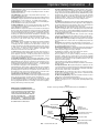
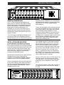
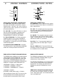
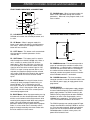
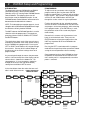
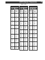
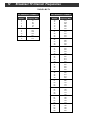
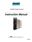
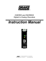
DAD860 and DAD860A
Digital to Analog Decoders
Instruction Manual
DAD860
LOCK
LINK
RS232
PROGRAM
TM
is a registered trademark of R. L. Drake LLC
© Copyright 2010 R.L. Drake LLC
P/N: 3852492-D-2010
2
Caution Statements
WARNING: TO PREVENT FIRE OR
ELECTRICAL SHOCK DO NOT
EXPOSE TO RAIN OR MOISTURE
A product and cart combination should be moved
with care. Quick stops, excessive force and uneven
surfaces may cause the product and cart combination to overturn.
RISK OF ELECTRIC SHOCK
DO NOT OPEN
The lightning flash with arrow head symbol, within
an equilateral triangle, is intended to alert the user
to the presence of uninsulated "dangerous voltage"
within the product's enclosure that may be of
sufficient magnitude to constitute a risk of electric
shock to persons.
CAUTION: TO REDUCE THE RISK OF ELECTRIC
SHOCK,
DO NOT REMOVE COVER
NO USER-SERVICEABLE PARTS INSIDE
REFER SERVICING TO QUALIFIED PERSONNEL
The exclamation point within an equilateral triangle
is intended to alert the user to the presence of
important operating and maintenance (servicing)
instructions in the literature accompanying
the product.
CAUTION
WARNING: TO REDUCE THE RISK OF FIRE OR ELECTRIC SHOCK, DO NOT EXPOSE THIS PRODUCT
TO RAIN OR MOISTURE.
DO NOT OPEN THE CABINET, REFER SERVICING TO QUALIFIED PERSONNEL ONLY.
CAUTION: TO PREVENT ELECTRIC SHOCK, DO NOT USE THIS (POLARIZED) PLUG WITH AN EXTENSION
CORD RECEPTACLE OR OTHER OUTLET UNLESS THE BLADES CAN BE FULLY INSERTED TO
PREVENT BLADE EXPOSURE.
ATTENTION: POUR PREVENIR LES CHOCS ELECTRIQUES, NE PAS UTILISER CETTE FICHE POLARISEE
AVEC UN PROLONGATEUR, UNE PRISE DE COURANT OU UNE AUTRE SORTIE DE COURANT, SAUF SI LES LAMES PEUVENT ETRE INSEREES A FOND SANS EN LAISSER AUCUNE
PARTIE A DECOUVERT.
Important Safety Instructions
3
14. Outdoor Antenna Grounding—If an outside antenna or cable system is
connected to the product, be sure the antenna or cable system is grounded so
as to provide some protection against voltage surges and built-up static
charges. Article 810 of the National Electrical Code, ANSI/NFPA 70, provides
information with regard to proper grounding of the mast and supporting
structure, grounding of the lead-in wire to an antenna discharge unit, size of
grounding conductors, location of antenna-discharge unit, connection to
grounding electrodes, and requirements for the grounding electrode.
See Figure A.
15. Lightning—For added protection for this product during a lightning storm,
or when it is left unattended and unused for long periods of time, unplug it from
the wall outlet and disconnect the antenna or cable system. This will prevent
damage to the product due to lightning and power-line surges.
16. Power Lines—An outside antenna system should not be located in the
vicinity of overhead power lines, other electric light or power circuits, where it can
fall into such power lines or circuits. When installing an outside antenna system,
extreme care should be taken to keep from touching such power lines or circuits
as contact with them may be fatal.
17. Overloading—Do not overload wall outlets, extension cords, or integral
convenience receptacles as this can result in a risk of fire or electric shock.
18. Object and Liquid Entry—Never push objects of any kind into this product
through openings as they may touch dangerous voltage points or short-out parts
that could result in a fire or electric shock. Never spill liquid of any kind on the
product.
19. Servicing—Do not attempt to service this product yourself as opening
or
removing covers may expose you to dangerous voltage or other hazards. Refer
all servicing to qualified service personnel.
20. Damage Requiring Service—Unplug this product from the wall outlet and
refer servicing to qualified service personnel under the following conditions:
a. When the power-supply cord or plug is damaged,
b. If liquid has been spilled, or objects have fallen into the product,
c. If the product has been exposed to rain or water,
d. If the product does not operate normally by following the operating
instructions. Adjust only those controls that are covered by the operating
instructions as an improper adjustment of other controls may result in damage
and will often require extensive work by a qualified technician to restore the
product to its normal operation,
e. If the product has been dropped or damaged in any way, and
f. When the product exhibits a distinct change in performance—this indicates
a need for service.
21. Replacement Parts—When replacement parts are required, be sure the
service technician has used replacement parts specified by the manufacturer
or have the same characteristics as the original part. Unauthorized substitutes
may result in fire, electric shock or other hazards.
22. Safety Check—Upon completion of any service or repairs to this product,
ask the service technician to perform safety checks to determine that the
product is in proper operating condition.
23. Wall or Ceiling Mounting—The product should be mounted to a wall or
ceiling only as recommended by the manufacturer.
24. Heat—The product should be situated away from heat sources such as
radiators, heat registers, stoves, or other products (including amplifiers) that
produce heat.
1. Read Instructions—All the safety and operating instructions should be read
before the product is operated.
2. Retain Instructions—The safety and operating instructions should be
retained for future reference.
3. Heed Warnings—All warnings on the product and in the operating
instructions should be adhered to.
4. Follow Instructions—All operating and use instructions should be followed.
5. Cleaning—Unplug this product from the wall outlet before cleaning. Do not
use liquid cleaners or aerosol cleansers. Use a damp cloth for cleaning.
6. Attachments—Do not use attachments that are not recommended by the
product manufacturer as they may cause hazards.
7. Water and Moisture—Do not use this product near water—for example,
near a bathtub, wash bowl, kitchen sink or laundry tub; in a wet basement;
or
near a swimming pool; and the like.
8. Accessories—Do not place this product on an unstable cart, stand, tripod,
bracket, or table. The product may fall, causing serious injury to a child or adult,
and serious damage to the product. Use only with a cart, stand, tripod, bracket,
or table recommended by the manufacturer, or sold with the product. Any
mounting of the product should follow the manufacturer's instructions, and
should use a mounting accessory recommended by the manufacturer.
9. A product and cart combination should be moved with care. Quick stops,
excessive force, and uneven surfaces may cause the product and cart
combination to overturn.
10. Ventilation—Slots and openings in the cabinet are provided for ventilation
and to ensure reliable operation of the product and to protect it from
overheating, and these openings must not be blocked or covered. The
openings should never be blocked by placing the product on a bed, sofa, rug,
or similar surface. This product should not be placed in a built-in installation
such as bookcase or rack unless proper ventilation is provided or the
manufacturer's instructions have been adhered to.
11. Power Sources—This product should be operated only from the type of
power source indicated on the marking label. If you are not sure of the type of
power supplied to your home, consult your product dealer or local power
company. For products intended to operate from battery power, or other
sources, refer to the operating instructions.
12. Grounding or Polarization—This product may be equipped with a polarized
alternating-current line plug (a plug having one blade wider than the other). This
plug will fit into the power outlet only one way. This is a safety feature. If you are
unable to insert the plug fully into the outlet, try reversing the plug. If the plug
should still fail to fit, contact your electrician to replace
your obsolete outlet.
Do not defeat the safety purpose of the polarized plug.
Alternate Warnings—If this product is equipped with a three-wire groundingtype plug, a plug having a third (grounding) pin, the plug will only fit into a
grounding-type power outlet. This is a safety feature. If you are unable to insert
the plug into the outlet, contact your electrician to replace your obsolete outlet.
Do not defeat the safety purpose of the grounding-type plug.
12 a. Mise à la terre ou Polarisation—Cet appareil est équipé avec un cordon
d'alimentation à trois fils. Il est a brancher sur une prise ayant un connecteur a
la terre. Assurez-vous que la connection a la terre ne manque pas.
13. Power-Cord Protection—Power-supply cords should be routed so that
they are not likely to be walked on or pinched by items placed upon or against
them, paying particular attention to cords at plugs, convenience receptacles,
and the point where they exit from the product.
Figure A
Example of antenna grounding as per National Electrical Code, ANSI/NFPA 70
NOTE TO CATV SYSTEM INSTALLERS:
THIS REMINDER IS PROVIDED TO CALL THE
CATV SYSTEM INSTALLER'S ATTENTION TO
ARTICLE 820 - 40 OF THE NEC THAT PROVIDES GUIDELINES FOR PROPER GROUNDING AND, IN PARTICULAR,
SPECIFIES
THAT THE CABLE GROUND SHALL BE CONNECTED TO THE
GROUNDING SYSTEM
OF THE BUILDING, AS CLOSE TO THE POINT
OF CABLE ENTRY AS PRACTICAL.
ANTENNA
LEAD IN
WIRE
GROUND CLAMP
ANTENNA
DISCHARGE UNIT
(NEC SECTION 810-20)
ELECTRIC
SERVICE
EQUIPMENT
GROUNDING CONDUCTORS
(NEC SECTION 810-21)
GROUND CLAMPS
NEC - NATIONAL ELECTRIC CODE
POWER SERVICE GROUNDING
ELECTRODE SYSTEM
(NEC ART 250, PART H)
4
Table of Contents / Specifications
TABLE OF CONTENTS
2
Caution Statements
3
Important Safety Instructions
4
Table of Contents / Specifications
5
General Description / Installation and Mounting
6
DAD860 and DAD860A Connections / Notes
7
DAD860 Controller Controls and Connections
8
DAD860 Setup and Programming
11 CATV Channel Frequencies
12 Broadcast TV Channel Frequencies
13 Service / If You Need To Call For Help
14 Warranty
DAD860 & DAD860A SPECIFICATIONS
RF INPUT
Frequency Range:
Channel Plans:
Input Channel BW:
Demod Modes:
Broadcast:
54 MHz to 864 MHz
Broadcast, STD CATV, HRC, IRC
6 MHz
8VSB, ATSC Standard18 video formats
CATV: 64QAM, 256QAM Annex B
Auto Detected
Symbol Rates:
8VSB: 10.76 MS/s
64QAM: 5.057 MS/s
256QAM: 5.3606 MS/s
Recommended
Input Level Range:
8VSB: -26 to +30 dBmV
64 QAM: -15 to +15 dBmV
256QAM -12 to +15 dBmV
Input Connector: Type F Female,
Impedance: 75 Ohms
Return Loss: 6 dB or better
ASI OUTPUT
Connector
TS Stream Type
Included Program(s)
(DAD860A only)
Front Panel BNC
MPTS or SPTS
All programs that are present in the
demodulated RF channel.
Clock DVB-ASI stream w.270 MHz clock.
NTSC VIDEO AND
AUDIO OUTPUTS
Video Output Connector:
Impedance:
Level:
Format:
VBI Data:
Type F, Female
75 Ohms
1 V p-p.
480i NTSC
NTSC Parental Control and EIA-608
Closed Captioning
Audio Outputs: L & R, Mono or Stereo
Level: 250 mV rms nominal, user adjustable
Aspect Ratio: AFD Ready.
User Programmable Cropped, Ltr Box, Stretched, AFD/Ltr
Box, AFD/Cropped
GENERAL
Power Requirement:
DAD860 5 VDC, 390 mA
12VDC, 220 mA
DAD860A 5 VDC, 550 mA
12 VDC @ 260 mA
Supplied by Drake PSM121 or RMM4
Dimensions and Weight:
DAD860 3.43” H x 1.024” W x 9.5” D
13.1 oz.
DAD860A 3.43” H x 1.024”W x 12.5” D
14.5 oz.
Specifications subject to change without notice or obligation.
General Description
5
PSM121 POWER SUPPLY
DAD860
DAD860
DAD860
DAD860
DAD860
DAD860
DAD860
DAD860
DAD860
DAD860
DAD860 Controller
DRAKE
DAD860
LOCK
LOCK
LOCK
LOCK
LOCK
LOCK
LOCK
LOCK
LOCK
LOCK
LINK
LINK
LINK
LINK
LINK
LINK
LINK
LINK
LINK
LINK
RS232
PROGRAM
RS232
PROGRAM
RS232
PROGRAM
RS232
PROGRAM
RS232
PROGRAM
RS232
PROGRAM
RS232
PROGRAM
RS232
PROGRAM
RS232
PROGRAM
RS232
PROGRAM
ENTER
UNIT
Parameters for the DAD860 can be set up with the
DAD860 Controller Module or by front panel RS232
connection to a PC running ‘DAD860 Remote
Control Software’.
GENERAL DESCRIPTION
The R. L. Drake DAD860 and DAD860A are high
quality, low noise, frequency agile, digital to analog
decoders designed for receiving digital signals from
off-air or CATV channels. Output of the DAD860 is
baseband NTSC video and stereo audio. The
DAD860A, only, has these NTSC outputs plus an
additional ASI output containing the entire demodulated transport stream for the tuned RF channel (all
programs included).
The one-unit wide module can be rack mounted using
the 12 position RMM12 rack mount, and is powered
by the Drake PSM121 Power Supply. Up to 10 units
plus the DAD860 Controller Module, or 12 units
without the Controller Module can be mounted in the
12 position rack mount. If no controller is required,
the RMM4 chassis and power supply may be used for
up to 4 DAD860s. DAD860As require more current
from the power supply and thus require the above
capacity to be reduced by two.
The NTSC output of a DAD860 or DAD860A can be
connected to VMM series modulators to place the
programming on an off-air or CATV channel, or to any
other device requiring baseband audio and video input.
If the DAD860 Controller is used, plug the supplied
cable into the COMM receptacle on its rear panel.
You will note that the other end of this cable terminates in ten three conductor female connectors.
Insert one of these connectors into the LINK receptacle on each of the DAD860s installed in the rack.
While these connectors can be inserted in any
order, it is suggested that cables be connected to
the DAD860s in numerical order from either left to
right or right to left - depending on which side of the
rack the DAD Controller is mounted.
INSTALLATION AND MOUNTING
Install the decoders in the RMM12 rack mounting
frame. Slide each module into the frame from the
front so that the mounting rails on the top and bottom
of the DAD engage the mounting tracks on the frame.
Similarly, mount the PSM121 Power Supply, again
making sure that its mounting rails line up with the
tracks in the frame. Apply the same mounting
procedure to the DAD860 Controller.
Note that, while the drawings on this page show only
DAD860s installed, various combinations of
DAD860(A)s and VMM600 or VMM860 modulators
could be installed in the same RMM12 or RMM4.
Connect an RF source (off-air or CATV) to the RF IN
connector on each unit and connect the VIDEO
OUT and AUDIO L and R connections to the appropriate inputs of each modulator or other desired
device.
Plug the supplied power cable into the receptacle on
the rear of the PSM121 Power Supply, and attach a
connector to the POWER receptacle on the rear of
each of the DAD860s, VMM modulators, and the
DAD860 Controller if used.
20
37
1
19
VIDEO OUT
100-240 V~
50/60 Hz 75 WATTS
~
+5 VDC
(4.5A Max)
Pins 1, 4, 7,
12, 15, 18,
21, 24, 27,
30, 33, 36
+12 VDC GND:
LINK
(3A Max)
Pins 10, 20,
Pins 2, 3, 5, 22, 23, 25,
6, 8, 9, 11, 26, 28, 29,
13, 14, 16, 31, 32, 34,
17, 19
35, 37
CONFORMS TO
UL STD 1950
CERTIFIED TO
CAN/CSA STD
C22.2 NO.950-95
R
VIDEO OUT
LINK
AUDIO
POWER
R
VIDEO OUT
LINK
AUDIO
POWER
L
R
Then connect the power supply power connector to
the appropriate power source using the supplied
line cord.
VIDEO OUT
LINK
AUDIO
POWER
L
R
VIDEO OUT
LINK
AUDIO
POWER
L
R
VIDEO OUT
LINK
AUDIO
POWER
L
R
VIDEO OUT
LINK
AUDIO
POWER
L
R
VIDEO OUT
LINK
AUDIO
POWER
L
R
VIDEO OUT
LINK
AUDIO
POWER
L
R
VIDEO OUT
LINK
AUDIO
POWER
L
R
COMM
AUDIO
POWER
L
L
POWER
+5V
+12V
GND
C
US
3008858
RF IN
RF IN
RF IN
RF IN
RF IN
RF IN
RF IN
RF IN
RF IN
RF IN
6
DAD860 / DAD860A
CONNECTIONS / NOTES
DAD860
R1
F1
VIDEO OUT
LOCK
LINK
LINK
R2
F2
R
POWER
L
R3
F3
RS232
PROGRAM
R5
AUDIO
R6
R4
RF IN
FRONT PANEL INDICATORS & CONNECTIONS
F1 - LOCK LED - This green LED lights continuously when the DAD860 is locked to the selected
incoming signal. If the lock is lost, such as when no
signal or a noisy signal is present, this LED will flash
on and off continuously
F2 - LINK LED - This amber LED flashes on and off
when the particular DAD860 is selected for programming by the DAD860 CONTROLLER or
‘DAD860 REMOTE CONTROL SOFTWARE’.
F3 - RS232 PROGRAM - This RS232 connector is
intended to attach to a PC running ‘DAD860 REMOTE CONTROL SOFTWARE’ for programming
the DAD860 as an alternative to using the DAD860
CONTROLLER module.
F4 - ASI OUTPUT, BNC CONNECTOR - not shown.
This BNC connector is only provided on the DAD860A
model and is located just above the LOCK LED.
REAR PANEL CONNECTIONS
R1 - VIDEO OUT - This “F” type connector supplies
the NTSC baseband video output to a modulator or
other suitable device.
R2 - LINK - This receptacle connects to one of the
ten serial cables from the DAD860 CONTROLLER
module for programming the desired parameters
into the DAD860.
R3 - POWER - This receptacle connects to one of
the twelve power cables from the PSM121 power
supply. The cable provides +5V, +12V and GND to
each device to which it is connected.
R4 - RF IN - This “F” type connector attaches to a
CATV (QAM) or off-air (8-VSB) digital TV signal
source.
R5 & R6 - AUDIO L & R - These two RCA Phono
connectors provide left and right stereo audio output
to a modulator or other suitable device.
RMM12 INSTALLATION OF DAD860 AND DAD860A
DAD860 CONTROL MODULE
The DAD860A draws additional current from the power
supply compared to the DAD860 model. Thus when
the DAD860A is paired with VMM series agile modulators, one less DAD860A/VMM pair can be used
compared to use with the VMM600 or VMM860 fixed
modulators. Example useable combinations are:
The DAD860 Control Module may be used to control
either the DAD860 or DAD860A. Models may be
mixed and use a single controller.
10 DAD860A + 1 PSM121 + 2 open spaces
6 DAD860A + 6 VMM600 + 1 PSM121
5 DAD860A + 5 VMM860AG/AS + 1 PSM121
12 DAD860 + 1 PSM121
6 DAD860 + 6 VMM (fixed or agile) + 1 PSM121
Other combinations are possible. The user must refer
to the specification for each model and make sure
that total load will not exceed the PSM121 rating.
The DAD860 Control Module is 2 units wide and thus,
if used, one pair of DAD/VMM must be replaced by
the controller. For example: one could control 10
DAD860 units but only 8 DAD860A units in one
RMM12.
RMM4 INSTALLATION OF DAD860 AND DAD860A
Any combination of DAD860, DAD860A, and VMM
series - either fixed or agile - can be mounted ‘on their
side’ in the RMM4 rack.
DAD860 Controller Controls and Connections
7
FRONT PANEL INDICATORS & CONNECTIONS
DAD860 Controller
F1
DRAKE
DAD860
F5
F7 - DOWN Button - When in program mode, this
button scrolls downward through the available
parameters. When not in the program mode, it will
have no effect.
6
F2
ENTER
F6
F3
UNIT
F4
F7
F1 - LCD DISPLAY - This displays the selected
DAD860 unit number, the selected parameter, and
its value.
F2 - UP Button - When in program mode, this
button scrolls upward through the available parameter values. When not in the program mode, this
button will have no effect.
F3 - LEFT Button - This button scrolls counterclockwise through the available parameters for the
selected unit.
F4 - UNIT Button - This button scrolls in numeric
order through the available DAD860 units. When a
unit is selected, its amber LINK LED will flash
continuously. While the LINK light is flashing, the
LCD will display the selected unit number and the
signal to noise ratio of the received signal or “NO
LOCK” if no signal is being received. After a unit is
selected, the controller backlight and the selected
unit’s amber LINK light will extinguish after approximately 40 seconds if there are no other control
inputs.
F5 - ENTER Button- Pressing this button for two
seconds will enter the program mode for the selected DAD860. This is indicated by the LCD
flashing on and off at an interval of approximately
one second. Once in the program mode, pressing
ENTER will store the value of the selected parameter and exit program mode.
F6 - RIGHT Button - When in program mode, pressing
this button will save the selected parameter value and
will then scroll clockwise to the next parameter, while
remaining in the program mode. When not in program
mode, it will scroll clockwise through available
parameters without saving any data. When in program
mode, it is also used to access secondary menus,
progress through secondary menu trees and to store
the value selections in these menus.
REAR PANEL INDICATORS & CONNECTIONS
COMM
POWER
R1
+5V
+12V
GND
R2
R1 - COMM Connector - This connector provides a
means of connecting the controller to each of the
DAD860 units. A supplied cable is attached to this
connector the other end of which is terminated in
ten numbered three conductor connectors. The
connector number corresponds to the unit number
of the DAD860 to which it is connected.
R2 - POWER Connector - This three conductor
connector connects to one of the twelve cables from
the PSM121 power supply to supply power for the
programmer.
POWER SUPPLY
The DAD860 requires multiple power supply voltages
that are all obtained from the Drake model PSM121
power supply module. The PSM121 mounts in the
RMM12 rack tray along with one to twelve DAD860
decoders (or other similar Drake models such as
VMM600 series modulators). The PSM121 provides
+5V, +12V and GND connections to each unit.
The PSM121 operates over a wide range of AC input
voltages from 90 VAC to 240 VAC, 50/60 Hz, and has
an 3 wire line cord receptacle. Power consumption
from the AC line will be around 60 W with twelve
DAD860 decoders installed. In many cases, the
power will be below this level.
8
DAD860 Setup and Programming
INTRODUCTION
The programming of each DAD860(A) in an RMM12
rack mounting frame is done with the DAD860
Controller, or by a PC running Drake ‘DAD860 Remote
Control Software’. The following discussion will
describe the use of the DAD860 Controller. Use of
‘DAD860 Remote Control Software’ will be covered in
documentation included with the software.
PROGRAMMING
To adjust and set a parameter value, enter the
program mode by pressing the center ENTER
button for approximately 3 seconds until the display
begins to flash. You are now in the program mode
and the UP and DOWN buttons will take you
through the various values for a given parameter.
Find the desired value for the selected parameter
and use the RIGHT arrow button to save that value
and progress to the next parameter, while remaining
in the program mode. (If the ENTER key is used,
the parameter value will be saved and program
mode exited.)
NOTE: The information presented on pages 8, 9, and
10 applies to the DAD860 and DAD860A even though
the references will only mention DAD860.
The UNIT button on the DAD860 Controller is used to
select the unit to be programmed. The actual programming is done via the UP, DOWN, LEFT, RIGHT
and ENTER buttons.
Proceed in this manner until all parameters have
been set to the desired value. Then press the
ENTER button to exit program mode and use the
UNIT key to proceed to the next DAD860 to be
programmed.
The chart below shows each of the menus that are
available for parameter value setup and/or viewing
for the DAD860 being programmed. Pressing the
LEFT or RIGHT arrow buttons will navigate through
these menus. You may do this without danger of
disturbing any of the current settings when not in
program mode.
Pressing the LEFT arrow button while in program
mode will back up to the previous parameter without
saving the current parameter value to memory.
Once programming for a given DAD860 has been
completed, the information will be retained in the
units memory until it is reprogrammed, even when
power is removed.
As you navigate through the menus the parameter
name is listed on the top line of the display and the
current value is shown on the bottom line. For
setup purposes, it is best to progress clockwise
through the chart (use the right arrow button),
starting from the default UNIT # screen.
In the chart below shows the values that are available in each of these menus. DAD860 CONTROLLER
MENU FLOW CHART
SYSTEM
BOOT UP
DRAKE
DAD860
UNIT #
SN xx dB
CH PLAN
OFF AIR
CATV STD
CATV HRC
CATV IRC
RF LIST
USE LIST
Current
Channel
MAN SEL
Select
Mode
MPEG PGM
AUD PID
USE LIST
MAN SEL
SCAN ADD
SCAN NEW
CLR LIST
Select
CH #
Select
MPEG #
Select
CH #
Select
Audio
PID #
SCAN
ADD
Select
Channel
Scanning
ADD
SCAN
NEW
CONFIRM?
Scanning
NEW
CLR LIST
CONFIRM?
CLEARING
RF #
MPEG #
NO MUTE
VERSION
NUMBER
MUTE SCR
WEAK SIG
AUDIO
BLUE SCR
NO VID
NO MUTE
MUTE
1. ENG
2. SPA
3. FRE
VOLUME
MODE
TV TYPE
0 - 100
STRETCH
LTR BOX
CROPPED
AFD/ LTR.
AFD/CROP
4:3
16:9
DAD860 Setup and Programming (cont.)
RF LIST SECONDARY MENUS
A DAD860 can store in its memory a list of all of the
digital channels and the MPEG programs they
contain, which it can receive from the CATV or offair signal source to which it is connected. The
values shown for the RF LIST parameter each lead
to secondary menus that allow manipulation of this
stored channel and MPEG information. The following is a description of each of these secondary
menu functions. These secondary menus can only
be accessed when in the program mode.
USE LIST - This function allows selection of the
desired channel and MPEG program from a channels LIST previously stored the DAD860’s memory.
From the “RF LIST” parameter screen USE LIST is
the default value.
1.
Press the RIGHT arrow button. “USE LIST”
and the currently stored channel number will be
displayed.
2.
Press the RIGHT button again. This will take
the operator to “RF # - MPEG # “ screen where the
desired channel and MPEG numbers can be
selected from the stored list using the UP and
DOWN arrow buttons.
3.
Press the RIGHT arrow button again to
save the value and proceed to the next parameter in
the primary menu.
MAN SEL - This function allows storage of a
particular RF channel and MPEG program value
whether or not signals are being received. It is also
used to select a specific audio PID if that is desired.
1.
From the “RF LIST” screen, use the UP or
DOWN arrow buttons to select MAN SEL.
2.
In the MAN SELECT menu, choose MPEG
PGM to select a specific MPEG program OR choose
AUD PID to select one specific audio PID on this RF
channel. Video from the program containing this audio
PID will play, if available. Enter PID in decimal format.
3.
Press the RIGHT arrow button. A MPEG
PGM or AUD PID RF CH# screen will appear.
4.
Use the UP and DOWN arrow buttons to
select the desired RF channel.
5.
Press the RIGHT arrow button again. If
MPEG PGM was chosen in step 2, the “MPEG PGM”
screen will appear. Use the UP and DOWN arrow
buttons to select the desired MPEG program number.
If AUD PID was chosen, a screen will appear to allow
setting any audio PID number, do so now.
6.
Press the RIGHT arrow button again. This
will take you to the “RF # - MPEG #” screen in the
main menu with the desired channel selected.
7.
Press the RIGHT arrow button again to save
the value and proceed to the next parameter in the
primary menu.
9
SCAN ADD - This function allows storage of an
additional channel to either a previously stored list or
an empty list, when the DAD860 is connected to a
signal source.
1.
From the “RF LIST” screen, use the UP and
DOWN arrow buttons to select SCAN ADD.
2.
Press the RIGHT arrow button. The “SCAN
ADD - CH 002” screen will appear.
3.
Use the UP and DOWN arrows to select the
desired channel.
4.
Press the RIGHT arrow button again. The
“SCAN ADD >>>>>” screen will appear followed
momentarily by the SCAN LOCK screen and on to
the “RF # MPEG” screen. At this point the unit will
exit program mode.
6.
At this point you can re-enter program
mode, proceed to the “RF # - MPEG #” screen and
select the desired MPEG number for the newly
added channel.
7.
Press ENTER to exit program mode.
NEW SCAN - This function is used to populate an
empty list when the unit is attached to a signal
source.
1.
From the “RF LIST” screen use the UP or
DOWN arrows to select NEW LIST.
2.
Press the RIGHT arrow button. The “SCAN
NEW” screen will appear.
3.
Press the RIGHT arrow button again. A
“CONFIRM?” screen will appear.
4.
An additional press of the RIGHT arrow
button will produce a “SCAN NEW - >>>>>>>>”
screen which will remain while the unit scans all
channels. This could take a minute or two.
5.
When scanning is complete, you will briefly
see a “LOCK” screen followed by the “RF # - MPEG
#” screen in the main menu. You can then select the
desired channel from the newly stored list and
proceed to the next parameter in the primary menu.
CLR LST - This function is used to erase all information from the units memory in preparation for
reprogramming.
1.
From the “RF LIST” screen, use the UP or
DOWN arrows to select CLR LIST.
2.
Press the RIGHT arrow button. This will
produce a “CLR LIST” screen.
3.
Press the RIGHT arrow button again. A
“CONFIRM?” screen will appear.
4.
An additional depression of the RIGHT
arrow will produce a “CLEARING - >>>>>>>>”
screen followed shortly by the “RF # - MPEG #”
screen which will now say “EMPTY”
5.
You can now press the LEFT arrow button
to return to the “RF LIST” screen where you can
select the method you wish to use to reprogram the
unit’s memory.
10
DAD860 Setup and Programming (cont.)
ADDITIONAL MENU ITEMS
RF # - MPEG # - This menu screen allows selection of the desired channel and MPEG program
from the list saved in memory or by one of the
methods in the secondary menus described previously.
UNIT # - SN - This is the default screen when a
DAD860 is selected. It displays the unit number of
the selected DAD860 as well as the signal to noise
ratio (SN) of the signal being received. If no signal
is being received. “NO LOCK” will be displayed
instead of a signal to noise ratio.
TV TYPE - Since the purpose of the DAD860 is
usually to provide 480i, 4:3 aspect ratio video for
display as a 480i signal, choose the 4:3 setting.
CH PLAN - This menu allows the selection of the
type of channel plan that will be received. The
choices are “OFF AIR”, “CATV STD”, “CATV HRC”
and “CATV IRC”. Tables showing channel number
vs frequency of CATV STD and OFF AIR (broadcast
TV) channel plans are shown on pages 11 and 12
respectively.
MODE - This selection determines how the video will
be displayed on the TV screen. One of the AFD
modes is recommended. “AFD/LTR” and “AFD/
CROP” use data that may be transmitted by the
broadcaster via the AFD (Active Format Description)
codes to automatically switch the DAD860’s output
between cropped or letterbox display to provide the
optimum viewing experience on a 4:3 TV. If no codes
are being transmitted, the aspect ratio will default to
“LTR BOX” or “CROPPED” respectively. If it is
desirable to ignore AFD codes and force a particular
mode, that may be done by selecting one of the
following settings.When wide screen video is being
received, “CROPPED” truncates the left and right
sides of the picture and expands it vertically to fill the
4:3 sized screen. Proper geometry is maintained.
This mode is sometimes called “Center Cut”.
“LTR BOX” will show the entire picture without
distortion, but will leave black bars above and below
the picture. “STRETCH” expands the picture vertically without cropping the left and right sides. The
“STRETCH” mode is seldom used.
VOLUME - This menu determines the audio output
level of the audio audio outputs. The selections are
from 0 to 100. Adjust for maximum audio level without
distortion. 85 is the default value.
AUDIO - Determines the language of the output
audio when multiple languages are available. The
choices are “1. ENG” (English), “2. SPA” (Spanish)
and “3. FRE” (French).
WEAK SIG - This is used to select the video output that
is to be displayed if the signal on the selected channel
is either absent or too weak for successful decoding.
The choices are “NO MUTE”, and “MUTE”. If “NO
MUTE” is selected, pressing the RIGHT button will
take the user directly to the VERSION NUMBER
screen. However if “MUTE” is selected, the MUTE
SCR screen appears with the choices of “BLUE SCR”
(blue screen) and “NO VID” (no video). Use the up or
down buttons to make the desired selection and press
the right button to proceed to the Version Number
screen. Muting, if selected, will occur if the SNR
drops to 15 dB, and the unit will unmute when the
SNR then reaches 17 dB or higher. With no muting
selected, the screen will still go to blue screen at
around 3 dB below usable 8VSB SNR.
PROGRAMMING WITH A PC
In addition to being programmed with the ‘DAD860
Controller’, the DAD860 can be programmed with a
PC running ‘DAD860 Remote Control Software’.
Connection to the PC is accomplished using a
standard RS232 serial cable connected from a
serial port on the PC to the RS232 serial port in the
front panel of the DAD860.
Details of the programming procedure are included
in the documentation supplied with the software.
Once programming is complete, the RS232 cable
may be removed from the DAD860. It is not necessary to leave the PC connected after programming
is complete.
MEMORY RETENTION
Regardless of whether a DAD860 is programmed
using the ‘DAD860 Controller’ or a PC running
‘DAD860 Remote Control Software’, a DAD860 will
retain the programming even if power is removed
for prolonged periods.
VERSION NUMBER - The firmware version number of
the selected DAD860 is displayed on this screen.
ADD’L INFO - MANUAL SELECT PROGRAMMING
1) The RF channel must always be entered
.
.
2) Enter the MPEG program number or an actual
audio PID number, but not both. When entering an
audio PID number, make sure the MPEG program
number is not programmed.
CATV Channel Frequencies
TABLE 1: CATV
CABLE TV CHANNELS
CABLE TV CHANNELS
CABLE TV CHANNELS
Channel
Number
Center of
Channel
Channel
Number
Center of
Channel
Channel
Number
Center of
Channel
EIA/NCTA
Numeric
Equivalent
Frequency
in MHz
EIA/NCTA
Numeric
Equivalent
Frequency
in MHz
EIA/NCTA
Numeric
Equivalent
Frequency
in MHz
2
3
4
5
6
95
96
97
98
99
14
15
16
17
18
19
20
21
22
7
8
9
10
11
12
13
23
24
25
26
27
28
29
30
31
32
33
34
35
36
37
38
39
40
57
63
69
79
85
93
99
105
111
117
123
129
135
141
147
153
159
165
171
177
183
189
195
201
207
213
219
225
231
237
243
249
255
261
267
273
279
285
291
297
303
309
315
321
41
42
43
44
45
46
47
48
49
50
51
52
53
54
55
56
57
58
59
60
61
62
63
64
65
66
67
68
69
70
71
72
73
74
75
76
77
78
79
80
81
82
83
84
85
327
333
339
345
351
357
363
369
375
381
387
393
399
405
411
417
423
429
435
441
447
453
459
465
471
477
483
489
495
501
507
513
519
525
531
537
543
549
555
561
567
573
579
585
591
86
87
88
89
90
91
92
93
94
100
101
102
103
104
105
106
107
108
109
110
111
112
113
114
115
116
117
118
119
120
121
122
123
124
125
126
127
128
129
130
131
132
133
134
135
597
603
609
615
621
627
633
639
645
651
657
663
669
675
681
687
693
699
705
711
717
723
729
735
741
747
753
759
765
771
777
783
789
795
801
807
813
819
825
831
837
843
849
855
861
11
12
Broadcast TV Channel Frequencies
TABLE 2: BC TV
VHF BROADCAST CHANNELS
Channel
Number
2
3
4
5
6
7
8
9
10
11
12
13
UHF BROADCAST CHANNELS
Center of Channel
Frequency (MHz)
Channel
Number
Center of Channel
Frequency (MHz)
57
63
69
79
85
177
183
189
195
201
207
213
14
15
16
17
18
19
20
21
22
23
24
25
26
27
28
29
30
31
32
33
34
35
36
37
38
39
40
41
42
43
44
45
46
47
48
49
50
51
52
53
54
55
56
57
58
59
60
61
62
63
64
65
66
67
68
69
473
479
485
491
497
503
509
515
521
527
533
539
545
551
557
563
569
575
581
587
593
599
605
611
617
623
629
635
641
647
653
659
665
671
677
683
689
695
701
707
713
719
725
731
737
743
749
755
761
767
773
779
785
791
797
803
Service / If You Need To Call For Help
SERVICE INFORMATION
You may contact the R.L. DRAKE Service Department for
additional information or assistance by calling
+1 (937) 746-6990, Monday through Friday, between
8:00 A.M. and 4:00 P.M. Eastern Time, except on holidays.
You may also contact the R.L. DRAKE Service Department by
E-mail at the following address:
[email protected]
or by Telefax:
+1 (937) 806-1576.
IF YOU NEED TO CALL FOR HELP
Call our Customer Service/Technical Support line at
+1 (937) 746-6990 between 8:00 A.M. and 4:00 P.M.
Eastern Time, weekdays. Please have the unit’s serial
number available. We will also need to know the specifics
of any other equipment connected to the unit.
When calling, please have the unit up and running, near
the phone if possible. Our technician(s) will likely ask
certain questions to aid in diagnosis of the problem. Also,
have a voltmeter handy, if possible.
R.L. DRAKE also provides technical assistance by
e-mail: [email protected]
or by Telefax: +1 (937) 806-1576.
Many of the products that are sent to us for repair are in
perfect working order when we receive them. For these
units, there is a standard checkout fee that you will be
charged. Please perform whatever steps are applicable
from the installation sections of the Owner's Manual
before calling or writing—this could save unnecessary
phone charges. Please do not return the unit without
contacting R.L. DRAKE first: it is preferred to help
troubleshoot the problem over the phone (or by mail) first,
saving you both time and money.
Inside the carton, enclose a note with your name, address, daytime phone number, and a description of the
unit’s problem.
The unit must be sent to the following address:
Service Department
R.L. DRAKE LLC
230 Industrial Drive
Franklin, Ohio 45005 U.S.A.
Be sure to include your street address which will be
needed for UPS return. UPS Surface (Brown Label) takes
7-10 days to reach us depending on your location, Blue
takes 2-3 days.
13
Should you want to return your unit for service, package
the unit carefully using the original carton or other suitable
container.
Write your return address clearly on the shipping carton
and on an enclosed cover letter describing the service
required, symptoms or problems. Also include your
daytime telephone number and a copy of your proof of
purchase.
The unit will be serviced under the terms of the
R.L. DRAKE LLC Limited Warranty and returned
to you.
Red is an overnight service. Send the unit in a way that it
can be traced if we can’t verify receipt of shipment. We
suggest UPS or insured postal shipment.
If the unit is still under the original owner’s warranty,
R.L. DRAKE will pay the cost of the return shipment to
you. Our return shipping policy is that we will return it UPS
Brown if received Brown or by US Mail, it will be returned
Blue if received Blue or Red—or it will be returned
however you prefer if you furnish the return cost for the
method you select.
If the unit is out of warranty, use one of the following
methods for return shipment:
1) You designate billing to American ExPress, VISA,
MasterCard or Discover card;
2) You prepay the service charges with a personal check,
or
3) You specify some other method of return and payment.
When calling, the technician can estimate the repair
charges for you over the phone. This is another good
reason to call before sending a unit in for repair.
Typically, equipment is repaired in five to ten working days
after it arrives at R.L. DRAKE if we have all the facts. If we
must call you, it may take longer. R.L. DRAKE is not
responsible for damage caused by lightning, nonprofessional alterations, “acts of God”, shipping damage, poor
storage/handling, etc. R.L. DRAKE will make note of any
shipping damage upon receipt.
You will need to send proof of purchase to receive
warranty service. Typically, a copy of the invoice from an
R.L. DRAKE dealer will suffice. The warranty is for the
original owner only and is not transferable.
14
Warranty
Three Year Limited Warranty
R.L. DRAKE LLC warrants to the original purchaser this product shall be free from defects in material or workmanship
for three (3) years from the date of original purchase.
During the warranty period the R.L. DRAKE LLC or an authorized Drake service facility will provide, free of charge,
both parts and labor necessary to correct defects in material and workmanship. At its option,
R.L. DRAKE COMPANY may replace a defective unit.
To obtain such a warranty service, the original purchaser must:
(1) Retain invoice or original proof of purchase to establish the start of the warranty period.
(2) Notify the R.L. DRAKE LLC or the nearest authorized service facility, as soon as possible after discovery of a
possible defect, of:
(a) the model and serial number,
(b) the identity of the seller and the approximate date of purchase; and
(c) A detailed description of the problem, including details on the electrical connection to associated equipment and
the list of such equipment.
(3) Deliver the product to the R.L. DRAKE LLC or the nearest authorized service facility, or ship the same in its original
container or equivalent, fully insured and shipping charges prepaid.
Correct maintenance, repair, and use are important to obtain proper performance from this product. Therefore
carefully read the Instruction Manual. This warranty does not apply to any defect that R.L. DRAKE LLC determines
is due to:
(1) Improper maintenance or repair, including the installation of parts or accessories that do not conform to the quality
and specifications of the original parts.
(2) Misuse, abuse, neglect or improper installation.
(3) Accidental or intentional damage.
All implied warranties, if any, including warranties of merchantability and fitness for a particular purpose, terminate
three (3) years from the date of the original purchase.
The foregoing constitutes R.L. DRAKE LLC entire obligation with respect to this product, and the original purchaser
shall have no other remedy and no claim for incidental or consequential damages, losses or expenses. Some states
do not allow limitations on how long an implied warranty lasts or do not allow the exclusions or limitation of incidental
or consequential damages, so the above limitation and exclusion may not apply to you.
This warranty gives you specific legal rights and you may also have other rights which vary from state to state.
This warranty shall be construed under the laws of Ohio.
For Service, contact:
R.L. DRAKE LLC
230 Industrial Drive
Franklin, Ohio 45005 U.S.A.
Customer Service and Parts Telephone: +1 (937) 746-6990
Telefax: +1 (937) 806-1576
World Wide Web Site: http://www.rldrake.com
R.L. Drake LLC
230 Industrial Drive
Franklin, Ohio 45005 U.S.A.
Customer Service and Parts Telephone: +1 (937) 746-6990
Telefax: +1 (937) 806-1576
World Wide Web Site: http://www.rldrake.com