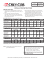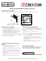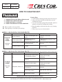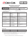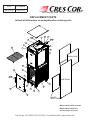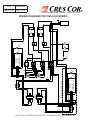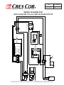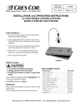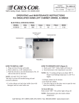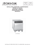
1
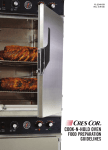
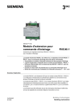
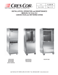
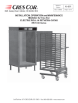
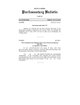
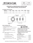
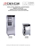
Ovens FL-2340-D Rev. 0 (5/13) Page 1 of 12 5925 Heisley Road • Mentor, OH 44060-1833 INSTALLATION, OPERATION and MAINTENANCE MANUAL for Cres Cor RADIANT OVENS 1000-CH-SS-SPLIT-D 1000-CH-AL-SPLIT-D 1000-CH-SS-SPLIT-D120 1000-CH-SS-D 1000-CH-AL-D Models: 1000-CH-D SERIES Cabinet model number: Cabinet serial number: Authorized Service Agency: Ph: Fax: Keep this manual for future reference. Call Toll-free: 877-CRES COR (273-7267) • Fax: 800-822-0393 • www.crescor.com Ovens FL-2340-D Rev. 0 (5/13) Page 2 of 12 5925 Heisley Road • Mentor, OH 44060-1833 TABLE OF CONTENTS SUBJECTPAGE INSTALLATION INSTRUCTIONS....................................................................................... 3, 4 OPERATING INSTRUCTIONS............................................................................................. 5, 6 Illustration, Control Panel............................................................................................. 5, 6 MAINTENANCE INSTRUCTIONS How to Clean the Unit................................................................................................... 7 Trouble Shooting Guide................................................................................................ 8 Replacement Parts......................................................................................................... 9 Illustration; Ovens......................................................................................................... 9 Wiring Diagram for 1000-CH-SS or 1000-CH-AL....................................................... 11, 12 Wiring Diagram for 1000-CH-SPLIT........................................................................... 13 SERVICE POLICY and AGENCY LIST.......................................................................... FL-1400 WARNING RISK OF FIRE OR ELECTRIC SHOCK DO NOT OPEN WARNING: TO REDUCE THE RISK OF FIRE OR ELECTRIC SHOCK, DO NOT REMOVE COVER (OR BACK) NO USER-SERVICEABLE PARTS INSIDE REPAIR SHOULD BE DONE BY AUTHORIZED SERVICE PERSONNEL ONLY Call Toll-free: 877-CRES COR (273-7267) • Fax: 800-822-0393 • www.crescor.com 5925 Heisley Road • Mentor, OH 44060-1833 Ovens FL-2340-D Rev. 0 (5/13) Page 3 of 12 INSTALLATION INSTRUCTIONS VENTING YOUR OVEN: 1. The purpose of ventilating hoods is to direct and capture smoke, grease-laden vapors, heat, odors, or fumes. 2. Low temperature equipment (maximum temperature 250°F/121°C) does not produce heat, odors, fumes, grease-laden vapors or smoke and is not required to be vented. 3. Most jurisdictions consider our low-temperature ovens (maximum temperature is 350°F/177°C) as low-heat appliances not requiring vent hoods. 4. Installation must conform with local codes. The authority having jurisdiction of enforcement of the codes will have the responsibility for making interpretations of the rules. SPECIFICATIONS: All units are rated 3000 watts. CMP MODEL NOS. ELECTRICAL SPECS (AC SERVICE) ELEC. LOAD POWER SUPPLY REQUIREMENT SINGLE OVENS Volts Ph Hz. Amps Volts Amps Ph Wire Volts NEMA 1000CHSSSPLITD 1000CHALSPLITD 208 240 1 1 60 60 14 13 208 240 20 20 1 1 2 2 208 240 6-20P 6-20P 1000CHSSSPLITD3 1000CHALSPLITD3 208 240 3 3 60 60 8 7 208 240 20 20 3 3 3 3 208 240 L15-20P L15-20P SPECIFICATIONS: All units are rated 6000 watts. *For USA Only - Canadian is 6-50P CMP MODEL NOS. ELECTRICAL SPECS (AC SERVICE) ELEC. LOAD POWER SUPPLY REQUIREMENT DOUBLE OVENS Volts Ph Hz. Amps Volts Amps Ph Wire Volts NEMA 1000CHSSD 1000CHSS2D 1000CHALD 208 240 1 1 60 60 29 25 208 240 30 30 1 1 2 2 208 240 *6-30P *6-30P 1000CHSSD3 1000CHSS2D3 1000CHALD3 208 240 3 3 60 60 16 14 208 240 20 20 3 3 3 3 208 240 L15-20P L15-20P SPECIFICATIONS: All units are rated 2000 watts. CMP MODEL NOS. ELECTRICAL SPECS (AC SERVICE) ELEC. LOAD POWER SUPPLY REQUIREMENT SINGLE OVENS Volts Ph Hz. Amps Volts Amps Ph Wire Volts NEMA 1000CHSSSPLITD120 120 1 60 16.6 120 20 1 2 120 5-20P Model number “AL” is aluminum outer body with stainless steel doors and interior. All models designed for AC Service. Model number may include a variety of informational suffix letters. NOTE: OVENS NEED TO BE INSTALLED BY A QUALIFIED PERSON. For models rated at 2/08/240 Volts: Check the voltage selector switch which is under an access cover on the back of the oven near the power cord. Flip the switch “UP” for 208 Volts Flip the switch “DOWN” for 240 Volts MAKE SURE THE SWITCH POSITION MATCHES YOUR POWER SOURCE. Call Toll-free: 877-CRES COR (273-7267) • Fax: 800-822-0393 • www.crescor.com Ovens FL-2340-D Rev. 0 (5/13) Page 4 of 12 5925 Heisley Road • Mentor, OH 44060-1833 INSTALLATION INSTRUCTIONS (continued) IDENTIFYING YOUR CABINET: Look for this label on the back of your cabinet. This information is needed when calling for questions or service. R 5925 HEISLEY RD. MENTOR, OHIO 44060 C US PL E MOD. 1000CH R SER. FAA-K5645C-001 Hz. 60 AMPS 29 M R 208/240 3000 SA VOLTS WATTS PH. 1 COMMERCIAL COOKING APPLIANCE MADE IN USA UPPER RIGHT CABINET CORNER HOW TO INSTALL CABINETS: 1. Remove all packing material from the inside and all vinyl from the outside of oven. 2. Place the oven in a well ventilated area on level floor. Clearance requirements: 3” (76mm) at the back, 2” (51mm) at the top, 1” (25mm) at both sides. 3. Install the pan slide racks on the sidewalls, if necessary. 4. Slide drip pan(s) onto the bottom of the compartment(s). All models are rated at 208/240 Volts. CSA certified to UL 197 Rev. 9 FOR FIRST-TIME OPERATION ONLY: A new oven needs to “burn off” factory oils and glue before it’s first use. Do NOT load food into oven until this has been done! 1. Push switch to “ON”; the light will come on. NOTE: The letters “LOTPR” (low temperature) will show on the control panel until it reaches 140°F (60°C). 2. Press the “COOK” button. 3. Push down and turn the control knob to show 200°F. Push the knob again to set the temperature. Run the unit for one (1) hour. 4. Turn the unit off and let cool. 5. Wipe the inside clean with detergent and hot water. HOW TO REVERSE THE DOOR OPENINGS, IF NEEDED: 1. Unscrew and remove the latch from the door and magnetic strike from the cabinet. 2. Unscrew the hinges from the cabinet body and remove door. 3. Remove the screws plugging the mating hinge, latch and strike holes on the opposite sides of the cabinet body and door. 4. Re-mount the hinges to the opposite side of the cabinet and door. 5. Remount the latch and strike to the opposite side DOOR VENT ADJUSTMENT: Open the door(s) and move the vent tabs on the inner door(s) as needed to release humidity. WARNING Air is VERY HOT when door is opened. Call Toll-free: 877-CRES COR (273-7267) • Fax: 800-822-0393 • www.crescor.com 5925 Heisley Road • Mentor, OH 44060-1833 Ovens FL-2340-D Rev. 0 (5/13) Page 5 of 12 OPERATING INSTRUCTIONS HOW TO USE THE COOK-N-HOLD CONTROL: *Push the lighted switch on the control panel; the light will come on and the cabinet will start heating. *The display will read “LOTPR” (low temperature) below 140°F. (60°C.). NOTE: Wait one (1) hour after start up before loading the food for best results. The display will read “PREHT” until the cabinet reaches the set temperature, then it will show “READY”. Cooking: 1. Press the COOK button. 2. Turn the control knob to the desired cooking temperature between 200°F (93°C) and 350°F (176°C). 3. Push the knob to set the temperature. 4. The control automatically goes to the HOLD mode. (Continue to step 1 below). Holding: (Press the HOLD button only if you are just holding food), 1. Turn the control knob to the desired holding temperature between 140°F (60°C) and 220°F (104°C). 2. Push the knob to set the temperature. 3. The control automatically goes to the TIME mode. Setting the time or Food Probe: 1. If NOT using the Food Probe: a) Turn the control knob to the desired hours/minutes. b) Push the knob to set the time. 2. Using the Food Probe: Plug in the food probe BEFORE you enter the TIME mode. Otherwise, you have to press the PROBE button to set the probe temperature. a) Turn the knob to the desired temperature. b) The timer will stop when the probe reaches the set temperature. 3. Press the START button. The display will read “PREHT” until the cabinet reaches the set temperature, then it will show “READY”. 4. Press the START again to use this recipe (see Recipes”). Note: Press the knob for 4 seconds to cancel the recipe. The DISPLAY button shows (cycles through) all the values when in each mode: • “PREHEAT” OR “READY”: momentarily shows the actual cabinet temperature. • “COOK” (Timed): shows Home screen, set point, count down time, actual cabinet temperature. • “COOK” (Probe): shows Home screen, set point, count up time, actual cabinet temperature. • “HOLD”: shows Home screen, set point, count up time, actual cabinet temperature. Call Toll-free: 877-CRES COR (273-7267) • Fax: 800-822-0393 • www.crescor.com 5925 Heisley Road • Mentor, OH 44060-1833 RECIPES: The control can hold up to 18 saved recipes. To save a recipe: 1. Press and hold both the TIME button and the knob for 5 seconds. The screen will be flashing. This is the setup menu. 2. Turn the knob through the menu until you get to “Edit”. 3. Press the knob and turn to the recipe you want to edit. There are 18 blank recipes to customize and save. 4. Press the knob and enter the cook, hold and time values. 5. After the entering the final value, “Edit” will show again. 6. Press the knob to edit more recipes or turn to “End” to exit the menu. To use one of the recipes: 1. Push one of the three RECIPE group buttons for the recipe number you want. 2. Turn the knob to the recipe you want and press the knob to select. 3. Press the START button to preheat. 4. After it shows “READY”, press the START button again to begin the recipe. Note: The display button will cycle through all the values as before, but will include the recipe number, if using a saved recipe. Ovens FL-2340-D Rev. 0 (5/13) Page 6 of 12 Quick Recipe Note: You can set “Quick Recipes” for recipes that you use often. This way, when you press a recipe group button and press start, that recipe will start cooking without searching for the recipe number. Recipe numbers can be set up as “quick recipes” as follows: 1. Press and hold both the TIME button and the knob for 5 seconds to get into the menu. 2. Turn the knob to “RBTN” and press the knob. The word “PUSH” will flash. 3. Press one of the recipe group buttons to assign a recipe. Note: Recipe numbers 1-6 can be set up as Group button 1. Recipe numbers 7-12 can be set up as Group button 2. Recipe numbers 13-18 can be set up as Group button 3. 4. Turn the knob to the recipe number you want to assign to that button and press the knob. Repeat the process to assign recipes to the other two recipe group buttons; or, turn the knob to “END” the submenu; turn to “END” the menu. Additional Menu Settings: Press and hold both the TIME button and the knob for 5 seconds to get into the menu. Here you can set the recipes, quick recipes, temperature units (°C or °F) and the datalog settings (USB connection required): ”RECE” allows you to enable or disable the data record feature. “RECF” allows you set how often (in minutes) a datapoint will be recorded. “RECD” allows you to set how long (in days) you would like the data to be stored in memory. Call Toll-free: 877-CRES COR (273-7267) • Fax: 800-822-0393 • www.crescor.com Ovens FL-2340-D Rev. 0 (5/13) Page 7 of 12 5925 Heisley Road • Mentor, OH 44060-1833 HOW TO CLEAN THE UNIT: WARNING BEFORE cleaning the cabinet: 1. 2. 3. 4. Unplug cord from wall. Allow cabinet to cool. Do NOT hose cabinet with water. Do NOT get water on controls. Do NOT use abrasives or harsh chemicals. Wipe up spills as soon as possible. Clean regularly to avoid heavy dirt build-up. Cleaning Hints: 1. Use the mildest cleaning procedure that will do the job. 2. Always rub in the direction of polish lines to avoid scratching the surface. 3. Use only a soft cloth, sponge, fibrous brushes, plastic or stainless steel pads for cleaning and scouring. 4. Rinse thoroughly with fresh water after every cleaning operation. 5. Always wipe dry to avoid water marks. MODELS: 1000-CH-SS-D & 1000-CH-SS-SPLIT-D STAINLESS STEEL CABINET Inside and Outside SOIL CLEANER METHOD Routine Cleaning Soap or mild detergent* and water. 1. Sponge on with cloth 2. Rinse Stubborn Spots, Stains Mild abrasive made for Stainless Steel. 1. Apply with damp sponge or cloth. 2. Rub lightly. Burnt on Foods or Grease Chemical oven cleaner made for Stainless Steel. Follow oven cleaner manufacturer’s directions. Hard Water Spots & Scale Vinegar 1. Swab or wipe with cloth. 2. Rinse and dry. MODELS: 1000-CH-AL-D & 1000-CH-AL-SPLIT-D (Aluminum cabinet outside only with stainless steel doors and pan slides) SOIL CLEANER Mild detergent* and hot water, or mild abrasive cleaner. Dirt ALUMINUM CABINET Outer body ONLY Fingerprints, Grease, Oil Water Spots METHOD 1. Use soft, damp cloth. 2. Rinse with hot water. 3. Wipe dry. Steam (no strong alkaline additive). 1. Rinse after steam cleaning. 2. Wipe dry. Detergent* and hot water. 1. Wipe with soft, damp cloth. 2. Rinse with hot water. 3. Wipe dry. Chemical oven cleaner made for aluminum. Follow oven cleaner manufacturer’s directions Mild abrasive cleaner. Oily or waxy cleaner. Apply with soft, clean cloth. Mild abrasive cleaner. Wipe with damp cloth. *Mild detergents include soaps and non-abrasive cleaners. Call Toll-free: 877-CRES COR (273-7267) • Fax: 800-822-0393 • www.crescor.com 5925 Heisley Road • Mentor, OH 44060-1833 Ovens FL-2340-D Rev. 0 (5/13) Page 8 of 12 MAINTENANCE INSTRUCTIONS TROUBLE-SHOOTING GUIDE WARNING IF UNIT GETS TOO HOT OR WON’T SHUT OFF, DISCONNECT POWER AT BRANCH PANEL. DO NOT UNPLUG CORD! If hot unit is NOT working, first check the following causes: 1. Cord is unplugged from wall outlet. 3. Switch(es) are turned off. 2. Circuit breaker/fuse to wall outlet is blown. 4. Thermostat(s) are turned off, or are set too low. IF THE OVEN TURNS ON: PROBLEM POSSIBLE CAUSE SOLUTION Oven does not heat, or doesn’t heat properly 1. Sensor 2. Heater relay 3. Loose connection 4. Oven control 5. High Limit 1. Replace 2. Replace 3. Replace 4. Replace 5. Replace Heater will not shut off 1. Control defective 2. Heater relay Vent fans do not shut off 1. Vent fan switch defective 2. Control compartment is still hot. 1. Replace 2. Replace 1. Replace 2. Wait until it cools Check “Heater will not shut off” Vent fans do not operate (See Note) 1. Vent fan switch defective 2. Vent fan defective 1. Replace 2. Replace Control will not switch from “COOK” to “HOLD” (timed mode) 1. Oven is in “PROBE” mode. 2. Oven control defective 1. Cancel recipe and switch to “TIMED” mode 2. Replace Control will not switch from “COOK” to “HOLD” (probe mode) 1. Oven is in the “TIMED” mode 2. Probe not plugged in 3. Probe defective 4. Oven control defective 1. Cancel recipe and switch to “PROBE” mode 2. Plug in probe 3. Replace 4. Replace Control will not switch to “COOK” (probe mode) 1. Oven in “TIMED” mode 2. Probe temperature setting lower than probe temperature 3. Probe not plugged in 4. Oven control defective 1. Switch to “PROBE” mode 2. Set probe temperature to desired temperature 3. Plug in probe 4. Replace CODE DISPLAYED CAUSE SOLUTION no p No meat probe Plug in probe Err0 Temp probe bad Replace ERROR CODES: NOTE: Vent fans will not operate until the control compartment requires ventilation to limit temperatures. Replacement of electrical components must be done by a qualified electrician. Refer to our Service Agency list, FL-1400 (found in the back of this manual), of authorized service centers. Instructions for replacing parts are included in replacement parts list. Call Toll-free: 877-CRES COR (273-7267) • Fax: 800-822-0393 • www.crescor.com Ovens FL-2340-D Rev. 0 (5/13) Page 9 of 12 5925 Heisley Road • Mentor, OH 44060-1833 REPLACEMENT PARTS Include all information on nameplate when ordering parts 7 8 9 24 23 27 28 4 3 2 22 5 1 6 26 INSULATION 18 14 11 12 12 29 SIDE PANEL 16 19 13 10 25 21 17 15 HEATER WIRE COVER Model 1000-CH-SS-D is shown. Model 1000-CH-SPLIT-D is half-size single door oven. Call Toll-free: 877-CRES COR (273-7267)FL-2340D • Fax: 800-822-0393 • www.crescor.com 1000CHSSSPLITD 5925 Heisley Road • Mentor, OH 44060-1833 Ovens FL-2340-D Rev. 0 (5/13) Page 10 of 12 REPLACEMENT PARTS Include all information on nameplate when ordering parts ITEM DESCRIPTION 1. Switch (On/Off) 2. Digital Control 3. Switch, Fan 4. Relay (1000-SPLIT-D) Relay (1000-SS-D) 5. Terminal Block (Input) 6. Terminal Block 7. Switch, toggle (240V) 8. Vent Fan (240V) Vent Fan (120V) 9. Fan Guard 10. Heater Kit 240V, 1325W Heater Kit 120V, 1000W 11. Door Latch Kit 12. Latch Strike Kit 13. Door Assembly 14. Door Gasket 15. Door Hinge 16. Casters, Rigid CMP Part No. 0808-125 0848-092-08-K 0848-034 0857-136 0857-134 0852-109 0852-091 0808-020 0769-174 0769-165 0769-167 0811-296-K 0811-295-K 1006-122-01-K 1006-122-02-K 1221-573-K 0861-267 0519-109 0569-306-R ITEM DESCRIPTION 17. Casters w/Brake 18. Pan Slides 19. Drip Pan 20. Hi-Limit 21. Drip Tray 22. Wire Shelf 23. Power Cord (3000W, 1Ph) Power Cord (6000W, 1Ph) Power Cord (3000W, 3Ph) Power Cord (6000W, 3Ph) Power Cord (2000W, 1Ph) 24. Strain Relief 25. Clear Drip Pan 26. Transformer 27. Fuse (1000-SS-D) 28. Fuse Holder (1000-SS-D) 29. Strainer Probe-Food 6” Probe Connector CMP Part No. 0569-306-B 0692-200 1017-115 0848-033 1017-111 1170-212 0810-173-01-K 0810-163-01-K 0810-164-02 0810-164-01 0810-065-1 0818-050 1017-058 0769-197 0807-150 0807-151 1052-094 0848-103 0848-106-02 Call Toll-free: 877-CRES COR (273-7267) • Fax: 800-822-0393 • www.crescor.com 18 N L N L Bottom Power Switch 17 16 15 RED 13 GRAY YELLOW PURPLE RED GRAY YELLOW PURPLE BOTTOM Transformer BLUE WHITE BROWN BLACK BLUE WHITE 20 19 18 17 25 24 25 24 N L Power Switch N L Top 23 22 31 30 K3 K1 K2 BOTTOM CABINET LOOKING AT REAR RENAU CONTROL Bottom Control Compartment Transformer BLACK BROWN 1 2 3 4 5 6 7 8 9 10 11 12 13 14 15 16 12 20 19 27 26 TOP TRIAD 23 27 3A 30 31 26 3A 15 14 MEAT PROBE fuse t° 21 fuse 22 bottom heaters top heaters 11 29 AIR PROBE t° 5 K3 K1 K2 TOP CABINET LOOKING AT REAR RENAU CONTROL 16 14 TB1 TB2 TB3 3 4 35 2 HIGH TEMP closes @130F 1 1 35 8 34 33 34 9 32 33 208V/240V Switch 32 28 1 2 3 4 5 6 7 8 9 10 11 12 13 14 15 16 10 28 29 t° MEAT PROBE 2 5 HIGH LIMIT VENT FAN 3 bottom cabinet 4 top cabinet HIGH LIMIT AIR PROBE VENT FAN t° 6 7 8 9 SSR BOTTOM SSR TOP 12 13 10 11 POWER CORD GROUND* Page 11 of 12 TRIAD Rev. 0 (5/13) L1 T1 L1 T1 FL-2340-D A2(-) A1(+) A2(-) A1(+) Ovens 5925 Heisley Road • Mentor, OH 44060-1833 WIRING DIAGRAM FOR 1000-CH-D SERIES Call Toll-free: 877-CRES COR (273-7267) • Fax: 800-822-0393 • www.crescor.com RED PURPLE POWER CORD GROUND* 12 VAC RED BLUE GRAY YELLOW GRAY 12 VAC YELLOW TRIAD HAMMOND BLUE BLACK WHITE BROWN ORANGE BLACK WHITE BROWN 208/240 VAC 208/240 VAC VENT FAN VENT FAN TERMINAL BLOCK blue brown TERMINAL BLOCK blue brown HIGH TEMP closes @130F 1 2 3 4 5 6 7 8 9 10 11 12 13 14 15 16 K3 K1 K2 AIR LOOKING AT REAR RENAU CONTROL t° TERMINAL BLOCK blue brown MEAT PROBE AIR PROBE HIGH LIMIT t° N L AIR HEATER SOLID STATE RELAY POWER SWITCH (rear view) N L L1 T1 5925 Heisley Road • Mentor, OH 44060-1833 Ovens FL-2340-D Rev. 0 (5/13) Page 12 of 12 WIRING DIAGRAM FOR 1000-CH-SS-SPLIT-D and 1000-CH-SS-SPLITD120 Call Toll-free: 877-CRES COR (273-7267) • Fax: 800-822-0393 • www.crescor.com A2(-) A1(+)