1
Manual
XANTO RT-Series
RT 1000
RT 2000
RT 3000
www.online-ups.com
Benutzerhandbuch
ONLINE XANTO RT-Serie
Version: 16. August 2010
Deutsch:
English:
Italia:
Seite
Page
Pagina
1 - 42
43 - 84
85 - 128
Deutschland
Italien
Schweiz
ONLINE USV-Systeme AG
Dreimühlenstraße 4
D-80469 München
Phone +49 (89) 2423990-10
Fax +49 (89) 2423990-20
www.online-usv.de
ONLINE UPS-Systems S.r.l.
Via Edison 12
I-20058 Villasanta (Milano)
Phone +39 (039) 2051444
Fax +39 (039) 2051435
www.online-ups.it
ONLINE USV-Systeme AG
Eigenheimstraße 11
CH-8304 Wallisellen (Zürich)
Phone +41 (44) 9452829
Fax +41 (44) 9453288
www.online-usv.ch
Seite 1 von 128
Seite 2 von 128
1. Inhalt
1.
Inhalt................................................................................3
2.
Abbildungsverzeichnis ..................................................5
3.
Tabellenverzeichnis........................................................6
4.
Einleitung ........................................................................7
5.
Sicherheitshinweise .......................................................8
6.
Produktbeschreibung...................................................12
6.1
6.2
6.2.1
6.2.2
7.
Funktionsprinzip...........................................................20
7.1
7.2
7.2.1
7.2.2
7.2.3
8.
Leistungselektronik..................................................20
Schnittstellenanschlüsse .........................................21
RS-232-Protokoll .....................................................22
Potentialfreie Kontakte.............................................22
Slot für optionale Schnittstellenkarten......................23
Installation.....................................................................24
8.1
8.1.1
8.1.2
8.2
8.3
9.
Ausstattungsmerkmale ............................................12
Systemkomponenten...............................................12
Steuereinheit ...........................................................13
Batteriepaket ...........................................................18
Tower-Installation ....................................................25
USV Single-Tower-Installation .................................25
USV plus Batteriepaket-Installation .........................26
Rack-Installation ......................................................27
Software-Installation ................................................27
Betrieb ...........................................................................28
9.1
9.2
9.2.1
9.2.2
9.3
9.3.1
9.3.2
9.3.3
9.4
Betriebsarten ...........................................................28
Einschalten..............................................................29
Normaler Start (Eingangsspannung vorhanden).....29
Kaltstart (Stromausfall) ............................................30
Ausschalten.............................................................30
Ausschalten im Normalbetrieb .................................30
Ausschalten im Batteriebetrieb ................................31
Ausschalten im Bypassbetrieb.................................31
Batterietest ..............................................................31
Seite 3 von 128
10. Wartung, Fehler beheben.............................................33
10.1
10.2
10.3
10.4
10.5
Lagerung .................................................................33
Batteriewartung .......................................................33
Wechseln der Ausgangssicherung ..........................34
Funktionsüberprüfung..............................................35
Fehlersuche.............................................................36
11. Technische Daten .........................................................38
11.1
11.2
11.3
11.4
Abmessungen, Gewicht...........................................38
Elektrische Spezifikationen......................................38
Umgebungsbedingungen.........................................40
Zertifizierungen........................................................41
12. Garantie .........................................................................42
Seite 4 von 128
2. Abbildungsverzeichnis
Abbildung 1: Vorderseite XANTO RT-Serie
13
Abbildung 2: Bedien- und Anzeigeelemente
14
Abbildung 3: Rückseite XANTO RT 1000
17
Abbildung 4: Rückseite XANTO RT 2000
18
Abbildung 5: Rückseite XANTO RT 3000
18
Abbildung 6: Vorderansicht Batteriepaket
19
Abbildung 7: Rückseite XANTO RT Batteriepaket
19
Abbildung 8: Blockschaltbild
20
Abbildung 9: Bodenplatte für Towermontage
25
Abbildung 10: Positionierung der USV
25
Abbildung 11: Bodenplatte mit Verlängerung
26
Abbildung 12: Anschluss Batteriepakete
26
Abbildung 13: Hot-Swap-Batterie bei XANTO RT 1000
34
Seite 5 von 128
3. Tabellenverzeichnis
Tabelle 1: Bedienelemente
15
Tabelle 2: Anzeigeelemente
15
Tabelle 3: Fehlercodes
(LED-Anzeige und akustische Signale)
Tabelle 4: Batterietypen
16
18
Tabelle 5: Überbrückungszeit mit zusätzlichen Batteriepaketen
(BP = Batteriepaket)
19
Tabelle 6: Pinbelegung der RS-232-Schnittstelle
22
Tabelle 7: Pinbelegung der Schnittstelle (DB9-Buchse)
23
Tabelle 8: Übersicht Schnittstellenzubehör
23
Tabelle 9: Lieferumfang
24
Tabelle 10: Fehlersuche
37
Tabelle 11: Abmessungen, Gewicht
38
Tabelle 12: Elektrische Spezifikationen
40
Tabelle 13: Umgebungsbedingungen
40
Tabelle 14: Zertifizierungen
41
Seite 6 von 128
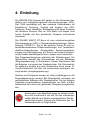
4. Einleitung
Die ONLINE USV-Systeme AG gehört zu den führenden Herstellern von unterbrechungsfreien Stromversorgungen (USV).
Seit 1988 beschäftigt sich das deutsche Unternehmen mit
Entwicklung, Fertigung, Vertrieb und Support von USVSystemen. Nach verkauften Stückzahlen sind deren Produkte
die deutsche Nummer Eins im USV-Markt und wegen ihrer
hohen Qualität und des exzellenten Supports international
anerkannt.
Die ONLINE XANTO RT-Serie ist eine unterbrechungsfreie
Stromversorgung (USV) in Doppelwandlertechnologie; Klassifizierung VFI-SS-111. Sie ist der perfekte Schutz für alle unternehmensrelevanten Datenverarbeitungs- und Telekommunikations-Anwendungen. Stromausfälle, Spannungsschwankungen und Überspannung, die Server und andere elektronischen Geräte beschädigen können, werden somit verhindert.
Das Doppelwandlerprinzip eliminiert alle Netzstörungen. Ein
Gleichrichter wandelt den Wechselstrom aus der Steckdose
(Eingangsspannung) in Gleichstrom. Dieser Gleichstrom lädt
die Batterien und speist den Wechselrichter. Der Wechselrichter wiederum erzeugt aus dem Gleichstrom einen neuen Sinus-Wechselstrom, mit dem die Verbraucher permanent versorgt werden (Ausgangsspannung).
Rechner und Peripherie werden so völlig unabhängig von der
Eingangsspannung versorgt. Bei Stromausfall versorgen die
wartungsfreien Batterien den Wechselrichter. Die bei anderen
Systemen unvermeidbaren Umschaltzeiten von Netz- auf Batteriebetrieb sind durch den gleitenden Übergang ausgeschlossen.
Änderungen oder Modifizierungen an diesem Gerät,
die nicht ausdrücklich von der für den standardgemäßen Betrieb des Geräts verantwortlichen Stellen
genehmigt wurden, können das Erlöschen des Garantieanspruchs zur Folge haben.
Seite 7 von 128
5. Sicherheitshinweise
VOR INSTALLATION UND INBETRIEBNAHME DAS BENUTZERHANDBUCH UND DIE SICHERHEITSHINWEISE
AUFMERKSAM LESEN UND BEACHTEN!
Transport
• USV-Anlage nur in der Originalverpackung transportieren
(Schutz gegen Stoß und Schlag).
Aufstellung
Aufgrund ihres Gewichtes werden für die Installation der USV
zwei Personen benötigt.
Dieses Gerät ist für die Installation in einem temperaturkontrollierten Raum, frei von leitfähigen verunreinigten Substanzen
bestimmt. Spezifizierungen zu den Umgebungsbedingungen
finden Sie in Kapitel 11.3.
• Wird die USV-Anlage aus kalter Umgebung in den Arbeitsraum gebracht, kann Betauung auftreten. Vor Inbetriebnahme muss die USV-Anlage absolut trocken sein. Deshalb eine Akklimatisationszeit von mindestens zwei Stunden abwarten.
• USV-Anlage nicht in der Nähe von Wasser oder in feuchter
Umgebung aufstellen.
• USV-Anlage nicht in direktem Sonnenlicht oder in der Nähe
von Wärmequellen aufstellen.
• Lüftungsöffnungen im Gehäuse der USV-Anlage nicht blockieren.
Seite 8 von 128
Anschluss / Elektrische Sicherheit
• Nie allein unter gefährlichen Bedingungen arbeiten.
• Stellen Sie den einwandfreien Zustand der Stecker, Steckdosen und Eingangskabel sicher.
• USV-Anlage nur an einer geerdeten Schutzkontaktsteckdose anschließen.
• Max. Stromaufnahme und ausreichende Absicherung der
Hausinstallation beachten.
• Die Steckdose der Hausinstallation (Schutzkontaktsteckdose) muss leicht zugänglich sein und sich in der Nähe der
USV-Anlage befinden.
• Nur VDE-geprüfte und CE-gekennzeichnete Verbindungsleitungen verwenden.
• Gemäß EMC-Richtlinie darf das an die USV angeschlossene Ausgangskabel nicht länger als 10m sein.
• Keine Haushaltsgeräte, wie beispielsweise Haartrockner,
an den USV-Ausgangssteckdosen anschließen.
• Keine Geräte an den USV-Ausgangssteckdosen anschließen, die die USV-Anlage überlasten (z. B. Laserdrucker).
• Leitungen so verlegen, dass niemand darauf treten oder
darüber stolpern kann.
Betrieb
• Netzkabel während des Betriebs nicht von der USV-Anlage
oder der Steckdose der Hausinstallation (Schutzkontaktsteckdose) abziehen, da sonst die Schutzerdung der USVAnlage und aller angeschlossenen Verbraucher aufgehoben wird.
• Die USV-Anlage verfügt über eine eigene, interne Stromquelle (Batterien). Die USV-Ausgangssteckdosen können
stromführend sein, selbst wenn die USV-Anlage nicht an
die Steckdose bzw. an die Einspeisung der Hausinstallation angeschlossen ist.
Seite 9 von 128
• Zum völligen Abschalten der USV-Anlage die OFF-Taste
für min. 2 Sek. drücken und dann das Netzkabel ziehen.
• Darauf achten, dass keine Flüssigkeit oder sonstigen
Fremdkörper in die USV-Anlage gelangen.
Wartung, Service, Störungen
• Die USV-Anlage enthält Spannungen, die gefährlich sind.
Reparaturen sind grundsätzlich nur von qualifiziertem Wartungspersonal durchzuführen.
• Außer der Batterie enthält diese Einheit keine vom Benutzer auszutauschenden Teile.
• Achtung - Gefahr von Stromschlägen. Selbst nach Trennung vom Stromversorgungsnetz (Steckdose) bleiben Bauteile innerhalb der USV-Anlage an die Batterien angeschlossen und befinden sich unter gefährlichem Spannungspotential. Vor der Durchführung von Service- und
Wartungsarbeiten Batterieversorgungskreis trennen und
Spannungsfreiheit überprüfen.
• Das Auswechseln der Batterien ist durch Personal mit
Sachkenntnis über Batterien und Kenntnis über die geforderten Vorsichtsmaßnahmen durchzuführen und zu überwachen. Unbefugte Personen sind von den Batterien fernzuhalten.
• Achtung - Gefahr von Stromschlägen. Der Batteriestromkreis ist von der Eingangsspannung nicht getrennt. Zwischen den Batterieanschlüssen und der Erde können gefährliche Spannungen auftreten.
• Batterien können Stromschlag verursachen und weisen
einen hohen Kurzschlussstrom auf. Bei Arbeiten mit Batterien sind u. a. folgende Vorsichtsmaßregeln zu beachten:
- Armbanduhren, Ringe oder andere Metallgegenstände
entfernen.
- Nur Werkzeuge mit isolierten Griffen verwenden.
• Beim Austauschen der Batterien dieselbe Anzahl und denselben Batterietyp verwenden.
Seite 10 von 128
• Batterien nicht ins Feuer werfen, die Batterien könnten
explodieren.
• Batterien nicht öffnen oder zerstören. Freigesetztes Elekrolyt ist schädlich für Haut und Augen. Es kann giftig sein.
• Zum Schutz vor einem Brand darf die Sicherung nur durch
einen gleichen Typ mit gleichem Nennwert ersetzt werden.
• USV-Anlage nicht auseinanderbauen.
Seite 11 von 128
6. Produktbeschreibung
XANTO RT ist eine intelligente ONLINE-USV (Güteklasse 1,
Klassifikation VFI-SS-111) mit höchster Systemverfügbarkeit.
Sie versorgt die angeschlossenen, sensiblen Geräte mit perfekter Sinus-Wechselspannung und schützt diese hiermit vor
Stromausfall und Spannungsschwankungen.
Das spezielle Produktdesign bietet vielfältige Einsatzmöglichkeiten. Je nach Kundenanforderung sowohl als Tower /
Standgerät als auch liegend im Rack. Ideal für Anwendungen
mit nur geringer Stellfläche wie beispielsweise Telekommunikationseinrichtungen, Serverräume usw.
6.1 Ausstattungsmerkmale
•
•
•
•
•
Nur 2 HE Bauhöhe.
Hot-Swap-Batterie.
XANTO RT 3000 mit Ausgangsklemmenanschluß.
Außergewöhnlich hohe Leistung, Wirkungsgrad >88%.
Sehr geringe Geräuschentwicklung (max. 43dB) durch
geregelte Lüfter.
• Hohe Systemverfügbarkeit, Selbstüberwachung und Fehlerdiagnose durch fortschrittliche DSP-Technologie.
• Große Eingangsspannungstoleranz mit unempfindlichem
Ausgang gegenüber Störungen der Eingangsspannung.
Passend für alle Anwendungsbereiche mit nicht konstanter
Energieversorgung.
• Große Eingangsfrequenz-Toleranz. Ideal zum Betrieb nach
Generatoren.
6.2 Systemkomponenten
XANTO RT besteht aus den beiden Grundelementen Steuereinheit und Batteriepaket.
Erstere ist für die Leistungsübertragung verantwortlich, vergleichbar mit dem Motor eines Kraftfahrzeuges und stellt die
Ausgangsspannung für die Last zur Verfügung. Darüber hinaus kontrolliert und lädt die Steuereinheit die Batterie. Das
Seite 12 von 128
Batteriepaket versorgt bei Stromausfall die USV mit Gleichspannung, vergleichbar mit dem Tank eines Kraftfahrzeuges.
6.2.1 Steuereinheit
Es gibt drei Modelle der Steuereinheit:
• 1kVA mit interner Batterie, keine Möglichkeit zur Erweiterung der Überbrückungszeit.
• 2kVA Steuereinheit ohne interne Batterie. Externes Batteriepaket zum Betrieb notwendig. Verlängerte Überbrückungszeit durch Parallelbetrieb mehrerer Batteriepakete
möglich.
• 3kVA Steuereinheit ohne interne Batterie. Externes Batteriepaket zum Betrieb notwendig. Verlängerte Überbrückungszeit durch Parallelbetrieb mehrerer Batteriepakete
möglich.
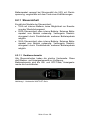
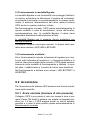
6.2.1.1 Gerätevorderseite:
Alle Steuereinheiten haben die gleiche Vorderseite. Diese
stellt Bedien- und Anzeigeelemente zur Verfügung.
Bedienelemente sind die ON- und OFF-Taste, Anzeigeelemente die Leuchtdioden.
Abbildung 1: Vorderseite XANTO RT-Serie
Seite 13 von 128
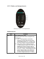
6.2.1.2 Bedien- und Anzeigeelemente:
Abbildung 2: Bedien- und Anzeigeelemente
Bedienelemente:
Taste
ON-Taste
Funktion
ON / Alarm-AUS-Taste:
Die ON / Alarm-Aus-Taste ermöglicht drei
Funktionen:
1.) USV / Wechselrichter einschalten:
Drücken der ON-Taste bis ein akustisches Signal ertönt (ca. 1–2 Sek.) und
die USV schaltet in den Normalbetrieb.
2.) Alarm AN / AUS (im Batteriebetrieb):
Im Batteriebetrieb ertönt alle 3 Sek. ein
akustisches Signal. Drücken Sie die
ON-Taste bis ein akustisches Signal ertönt (ca. 1-2 Sek.). Anschließend ist das
period. Signal inaktiv. Zum Aktivieren
drücken Sie die ON-Taste erneut bis
ein akust. Signal ertönt (ca. 1-2 Sek.).
Seite 14 von 128
3.) Batterietest aktivieren (im Normalbetrieb):
Halten Sie die ON-Taste gedrückt bis
ein akustisches Signal ertönt (ca. 1–2
Sek.)
OFF-Taste
Die OFF-Taste hat 2 Funktionen:
1.) Wechselrichter Ausschalten:
Drücken Sie im Normal- oder Batteriebetrieb die OFF-Taste (ca. 1–2 Sek.)
und der Wechselrichter schaltet aus.
Die Ausgangssteckdosen sind jetzt
spannungsfrei.
2.) Bereitschaftsbetrieb:
Drücken Sie im Bypassbetrieb die
OFF-Taste (ca. 1–2 Sek.) und die USV
schaltet den Ausgang spannungsfrei.
Tabelle 1: Bedienelemente
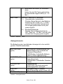
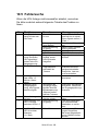
Anzeigeelemente:
Die Bedeutung der Leuchtdioden-Anzeige ist in der nachfolgenden Tabelle beschrieben:
BATTERY-LED
(grün)
INVERTER-LED
(grün)
BYPASS-LED
(grün)
LINE-LED
(grün)
ALARM-LED (rot)
USV-Betrieb / Batteriebetrieb und
Batteriespannung innerhalb der
Toleranz (Dauerlicht).
LED-Blinken: Fehlerhafte Batterie
oder zu hohe Ladespannung.
Normalbetrieb / Wechselrichterbetrieb (Dauerlicht).
LED-Blinken: Fehlerhafter Wechselrichter.
Bypassbetrieb.
ACHTUNG: Die Last wird nicht
batteriegepuffert versorgt!!!
Netzspannung in Toleranz.
Bei Stromausfall erlischt diese LED.
Fehler, bspw. Überlast.
Tabelle 2: Anzeigeelemente
Seite 15 von 128
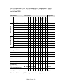
Die Kombination von LED-Anzeige und akustischem Signal
beschreibt einen der nachfolgend definierten Zustände (siehe
auch Kap.10.5):
Normalbetrieb
(Last)
0 – 25%
z
26 – 50%
z
z
51 – 75%
z
z
z
76 – 100%
z
z
z
z
101 – 105%
z
z
z
z
> 105%
z
z
z
z
Batteriebetrieb
(Kapazität)
Battery
Inverter
kein
z
z
Kein
z
z
Kein
z
z
z
Kein
z
z
z
2x / Sek.
z
z
z
z
1x / 3 Sek.
z
z
z
z
z
1x / 3 Sek.
z
z
z
z
z
z
1x / 3 Sek.
z
z
z
z
z
z
1x / 3 Sek.
z
Ladegerät-Fehler
z
Übertemperatur
z
z
Wechselrichter-Fehler
z
}
}
Dauernd
z
}
}
Dauernd
z
}
}
Dauernd
z
}
}
z
}
}
z
}
}
z
}
}
Überlast
z
z
z
z
z
Batterie defekt (Normalbetrieb)
Batterie defekt
(Bereitschaftsbetrieb)
}
}
}
}
}
z
}
}
}
}
}
}
Keine Batterie
}
}
}
}
}
z
z = EIN
Bypass
z
z
Gleichrichter-Fehler
Line
z
1x / Sek.
Kurzschluss
Lüfter-Fehler
Alarm
Kein
z
51 – 75%
z
z
z
26 – 50%
>96%
z
z
0 – 25%
76 – 95%
5
Signalton
4
3
2
LED-Anzeige
1
Betriebsart
} = von weiterem Betriebszustand abhängig
Tabelle 3: Fehlercodes (LED-Anzeige und akustische Signale)
Seite 16 von 128
}
}
1x / Sek.
Dauernd
Ï
Dauernd
Dauernd
z
}
Ï
Kein
Ï
Kein
Ï 6x
Ï = Blinken
ACHTUNG:
LED 5 = gelb,
ALARM-LED = rot,
alle anderen = grün
6.2.1.3 Geräterückseite:
Die Rückseiten der Steuereinheiten sind unterschiedlich.
Die Rückseite verfügt über:
• Eingangssteckdose, ausgeführt als Kaltgerätestecker
(männlich/male).
• Überstromschutzeinrichtung.
• Ausgangssteckdosen ausgeführt als 10A Kaltgerätebuchse
sowie Klemmenblock bei 3kVA-Steuereinheit.
• Anschlussbuchse für externes Batteriepaket (nicht 1kVASteuereinheit).
• DB9-Buchse (männlich/male) für RS-232-Kommunikation
und potentialfreie Kontakte.
• Slot für optionale Schnittstellenkarten (SNMP- / Netzwerkmanagementkarte basic, SNMP- / Netzwerkmanagementkarte professionell, USB-Karte).
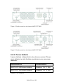
Abbildung 3: Rückseite XANTO RT 1000
Seite 17 von 128
Abbildung 4: Rückseite XANTO RT 2000
Abbildung 5: Rückseite XANTO RT 3000
6.2.2 Batteriepaket
Das Batteriepaket ist in zwei unterschiedlichen Versionen
verfügbar. Die Abmessungen sowie Beschaffenheiten von
Vorder- und Rückansicht sind jedoch identisch:
Bezeichnung
Eigenschaften
XANTO RT 2000 Batteriepaket
6x 12V / 7,2Ah Batterie
XANTO RT 3000 Batteriepaket
6x 12V / 9,0Ah Batterie
Tabelle 4: Batterietypen
Seite 18 von 128
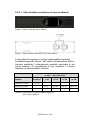
6.2.2.1 Batteriepaket Vorder- und Rückansicht:
Abbildung 6: Vorderansicht XANTO RT Batteriepaket
Abbildung 7: Rückseite XANTO RT Batteriepaket
Die Wahl der Buchse für Ein- oder Ausgang ist beliebig!
Die verlängerte Überbrückungszeit bei optionaler Parallelschaltung mehrerer Batteriepakete kann der nachfolgenden
Tabelle entnommen werden. Es wird dringend empfohlen die
max. Anzahl an Batteriepaketen nicht zu überschreiten:
Überbrückungszeit (Min.)
bei 50% / 100% Last
Modell
Standard
+ 1 BPs
+ 2 BPs
+ 3 BPs
+ 4 BPs
XANTO RT 1000
18 / 6
-
-
-
-
XANTO RT 2000
-
17 / 6
52 / 20
94 / 37
122 / 54
XANTO RT 3000
-
12 / 5
37 / 16
55 / 26
78 / 40
Tabelle 5: Überbrückungszeit mit zusätzlichen Batteriepaketen
(BP = Batteriepaket)
Seite 19 von 128
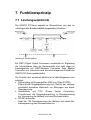
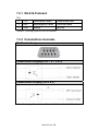
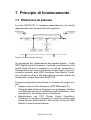
7. Funktionsprinzip
7.1 Leistungselektronik
Die XANTO RT-Serie besteht im Wesentlichen aus den im
nachfolgenden Blockschaltbild dargestellten Modulen:
Abbildung 8: Blockschaltbild
Ein DSP (Digital Signal Prozessor) verarbeitet im Signalweg
die Informationen über die Stromqualität und setzt diese im
Leistungskreis mit IGBT-Modulen (Insulated Gate Bipolar
Transistor) um. Hierdurch wird die herausragende Qualität der
XANTO RT-Serie gewährleistet.
Die Funktion der einzelnen Module ist im Nachfolgenden kurz
erläutert:
• Netzeingang mit Eingangsfilter (EMI und Class D SPD):
Filterung der Eingangsspannung zum Schutz der nachgeschalteten sensiblen Elektronik vor Störungen wie bspw.
Überspannung.
• Gleichrichter mit PFC (Power Factor Correction):
Transformiert die Eingangsspannung in Gleichspannung
zur Versorgung der Batterie und des Wechselrichters.
• DC/DC-Konverter:
Hebt die 12V-Gleichspannung der Batterie auf ideale Betriebsspannung des Wechselrichter an.
Seite 20 von 128
• Wechselrichter:
Im Normalbetrieb wandelt er die Gleichspannung des
Gleichrichters in präzise Wechselspannung zur Versorgung
der Last mit konstant 230V, 50Hz. Im Batteriebetrieb wird
der Wechselrichter aus der Batterie versorgt.
• Bypass:
Im Fehlerfall, bspw. Übertemperatur oder Überlast schützt
der Bypass die interne Elektronik vor Zerstörung. Im Fehlerfall wird die Lastversorgung autom. auf Bypassbetrieb
geschaltet und die Verbraucher OHNE Batteriepufferung
aus dem regulären Haus-Stromnetz versorgt. Dieser Betriebszustand wird über die Frontpanel-Anzeige sowie als
Information über die Software signalisiert.
• Ladegerät:
Das interne Ladegerät versorgt die Batterien im Ladezustand mit einer konstanten Stromstärke von 1A.
• Batterie / Akku:
Wartungsfreier, verschlossener Blei-Gel-Akku.
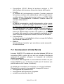
7.2 Schnittstellenanschlüsse
Die XANTO RT-Serie verfügt an der Rückseite der USVAnlage über einen DB9-Port als auch über einen Slot für optionale Schnittstellenkarten. An beiden können Computer angeschlossen werden.
Die DB9-Buchse unterstützt die Kommunikation über das RS232-Protokoll sowie potentialfreie Kontakte.
Diese Anschlüsse ermöglichen
• Überwachung der USV-Anlage,
• Überwachung der Eingangsspannung,
• Automatische Sicherung von Daten,
• Abschaltung des Computers und
• Abschaltung der USV-Anlage.
Die Funktionen werden von der im Lieferumfang enthaltenen
DataWatch-Software unterstützt.
Seite 21 von 128
7.2.1 RS-232-Protokoll
Pin
2
3
5
TxD
RxD
GND
Gesendete Daten
Empfangene Daten
Masse
transmitted data
Received data
ground
Tabelle 6: Pinbelegung der RS-232-Schnittstelle
7.2.2 Potentialfreie Kontakte
Pin-Beschreibung
Potentialfreie Ausgänge (Pin 1 & 7, 8 & 9) *
Potentialfreier Eingang (Pin 4 & 5) *
* Max. Spannung / Stromstärke an Pins 1, 4, 5, 7, 8 und 9 ist 30V DC, 10mA
Seite 22 von 128
Pin
1
2
3
4
5
6
7
8
9
Beschreibung
Batterie leer (open collector)
USV TxD (typ. RS-232-level)
USV RxD (typ. RS-232-level)
Remote Inverter OFF 5-12V DC, 10-24mA
(im Batteriebetrieb)
GND
Batterie leer (open emitter)
Batteriebetrieb (open emitter)
Batteriebetrieb (open collector)
Tabelle 7: Pinbelegung der Schnittstelle (DB9-Buchse)
Bemerkungen:
1.) Pin 1 & 7: Potentialfreier Ausgang. Bei normaler Batteriespannung geöffnet. Bei niedriger Batteriespannung geschlossen.
2.) Pin 4 & 5: Potentialfreier Eingang. Bei Anlegen einer Hilfsspannung (5-12V DC) im Batteriebetrieb für min. 20 Sekunden schaltet die USV aus. Sonst keine Funktion.
3.) Pin 8 & 9: Potentialfreier Ausgang. Bei Normalbetrieb geöffnet, bei Batteriebetrieb geschlossen.
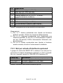
7.2.3 Slot für optionale Schnittstellenkarten
XANTO RT ist mit einem Steckplatz für optionale Schnittstellenkarten ausgestattet. Mit diesem sind die nachfolgenden
Produkte der ONLINE USV-Systeme AG kompatibel:
Art.-Nr.
DW5SNMP30
DW7SNMP30
PHXUSB
Beschreibung
Netzwerkmanagementkarte, professionell
Netzwerkmanagementkarte, basic
USB-Karte
Tabelle 8: Übersicht Schnittstellenzubehör
Seite 23 von 128
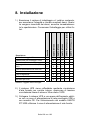
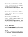
8. Installation
Beschreibung
Anzahl
XANTO RT 1000
XANTO RT 2000
XANTO RT 3000
XANTO RT 2000 Batteriepaket
XANTO RT 3000 Batteriepaket
1.) Überprüfen Sie den Verpackungskarton und den Inhalt auf
Vollständigkeit und evtl. Schäden. Sollten Sie Schäden
feststellen, informieren Sie sofort den Spediteur. Bewahren Sie die Verpackung für künftige Verwendungszwecke
auf.
19“-Montagewinkel
2
X
X
X
X
X
Bodenplatte für Towermontage
2
X
X
X
-
-
Bodenplatte, Verlängerung
2
-
-
-
X
X
10A Kaltgeräteverlängerung
2
X
X
X
-
-
16A Netzanschlußkabel
1
-
-
X
-
-
Batteriekabel
1
-
-
-
X
X
Schnittstellenkabel
1
X
X
X
-
-
Software DataWatch
1
X
X
X
-
-
Bedienungsanleitung
1
X
X
X
-
-
Tabelle 9: Lieferumfang
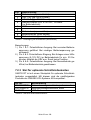
2.) Die USV wird durch interne Lüfter mit forciertem Luftstrom
gekühlt. Gewährleisten Sie, dass min. 30cm Abstand hinter der USV zur Verfügung stehen.
3.) Schließen Sie die USV-Anlage über ein VDE-geprüftes
und CE-gekennzeichnetes Netzkabel an eine Schutzkontaktsteckdose der Hausinstallation an. Zum Anschluss der
XANTO RT 3000 verwenden Sie das mitgelieferte Netzkabel.
Seite 24 von 128
ACHTUNG:
Die Ausgangssteckdosen der USV stehen nun
unter Spannung. Dies wird durch die LINE- und
BYPASS-LED signalisiert!
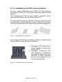
8.1 Tower-Installation
8.1.1 USV Single-Tower-Installation
Bitte verwenden Sie die im Lieferumfang enthaltenen Bodenplatten. Entnehmen Sie diese dem Karton und fügen Sie sie
wie nachfolgend abgebildet zusammen.
Abbildung 9: Bodenplatte für Towermontage
Nach dem Zusammenfügen der beiden separaten Komponenten bitte die USV wie folgt platzieren.
Abbildung 10: Positionierung der USV
Seite 25 von 128
8.1.2 USV plus Batteriepaket-Installation
Für alle USV-Anlagen der XANTO RT-Serie (Ausnahme XANTO RT 1000) sind zusätzliche Batteriepakete erhältlich.
Zur Installation von USV und Batteriepaket bitte annähernd
analog Kap. 8.1.1 verfahren.
Für maximale Standfestigkeit die Verlängerung der Bodenplatte (liegt dem Batteriepaket bei) verwenden. Die Größe variiert
nach Anzahl der zusätzlich verwendeten Batteriepakete.
Abbildung 11: Bodenplatte mit Verlängerung
Verwenden Sie das Batteriekabel (liegt dem Batteriepaket bei)
um die USV mit dem Batteriepaket zu verbinden:
1.) Trennen Sie die USV-Anlage
vom Stromversorgungsnetz
und die Verbraucher von der
USV-Anlage.
2.) Verbinden Sie das eine Ende
des Batteriekabels mit dem
Anschluß für die externe Batterie an der Rückseite der
USV und das andere Ende
mit einer beliebigen Buchse
an der Rückseite des Batteriepaketes.
Abbildung 12: Anschluss Batteriepakete
HINWEIS:
Bei Betrieb mit einem externen Batteriepaket
verlängert sich der Ladevorgang auf 24 Stunden,
bzw. auf 48 Stunden bei zwei Batteriepaketen
nach Totalentladung.
Seite 26 von 128
ACHTUNG:
Die XANTO RT 2000 und XANTO RT 3000 haben
keine internen Batterien. Zur einwandfreien Funktion muss die USV mit einem Batteriepaket verbunden werden!
8.2 Rack-Installation
Bei Installation in einem Rack muss ein standardisiertes
19“-Rack mit einer Tiefe von mindestens 400mm verwendet
werden. Bitte zur optimalen Gewichtsverteilung unsere optionalen Montageschienen Art.-Nr. „Rack-Kit“ oder schrankherstellerspezifische Montageschienen verwenden!
1.) Verwenden Sie die im Lieferumfang enthaltenen Montagewinkel.
2.) Entfernen Sie die M4x8-Schrauben an beiden Seitenteilen
der USV (4 Stück je Seite).
3.) Befestigen Sie die Montagewinkel mit den zuvor entfernten Schrauben.
4.) Plazieren Sie die USV im Rack und fixieren Sie sie.
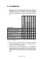
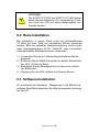
8.3 Software-Installation
Zur Installation der Shutdown-, Management- und Monitoringsoftware DataWatch beachten Sie bitte die separate Anleitung
auf der CD.
Seite 27 von 128
9. Betrieb
1.) Laden Sie die Batterien vollständig auf, indem Sie die
USV-Anlage für 1-2 Stunden am Stromversorgungsnetz
anschließen. Sie können die USV-Anlage auch unmittelbar ohne Laden einsetzen, doch kann dann die Überbrückungszeit kürzer als der angegebene Nennwert sein.
2.) Stellen Sie sicher, dass die Ausgangsspannung der USVAnlage mit der Spannung Ihres Computers übereinstimmt
(in der Regel 230V). Sie können die Ausgangsspannung
der USV-Anlage mit der Software einstellen.
3.) Schließen Sie Ihre Computer über die mitgelieferten 10A
Kaltgeräteverlängerungskabel an die USV-Ausgangssteckdosen an.
ACHTUNG:
Schließen Sie keine Geräte an die USVAusgangssteckdosen an, die die USV-Anlagen
überlasten (z.B. Laserdrucker). Schließen Sie
keine Haushaltsgeräte an die USV-Anlage an.
9.1 Betriebsarten
XANTO RT verfügt über drei Betriebsarten:
1.) Normalbetrieb:
Die Last wird vom Wechselrichter versorgt, solange die Versorgungsspannung innerhalb der definierten Toleranz liegt.
Hierbei erhält der Wechselrichter Energie vom Gleichrichter.
In diesem Betriebszustand leuchten die „LINE“ und „INVERTER“ LEDs.
Seite 28 von 128
2.) Bypass-Betrieb:
Der Bypass-Modus ist eine Schutzeinrichtung der internen
Elektronik. Er verhindert die Zerstörung dieser als Folge von
unzulässig hoher Stromstärke oder Übertemperatur.
Im Normalbetrieb schaltet die USV bei Überlastung, Wechselrichterfehler, Übertemperatur usw. automatisch in diesen Modus. Im Bypassmodus wird die Last unmittelbar von der Eingangsspannung versorgt.
Im Bypass-Modus existiert kein Schutz mit Batteriepufferung!
Die Batterie wird weiterhin geladen. In diesem Betriebszustand leuchten die „LINE“ und „BYPASS“ LEDs.
3.) Batteriebetrieb:
Verlässt die Eingangsspannung im Normalbetrieb die definierten Spannungs- und/oder Frequenztoleranzen, bzw. tritt ein
absoluter Stromausfall auf, so schaltet die USV autom. und
unterbrechungsfrei in den Batteriebetrieb. Der Gleichrichter
und das Lademodul sind hierbei inaktiv.
Im Batteriebetrieb leuchten die „BATTERY“ und „INVERTER“
LEDs.
9.2 Einschalten
Es gibt zwei Möglichkeiten um die USV einzuschalten:
9.2.1 Normaler Start
(Eingangsspannung vorhanden)
Verbinden Sie die USV mit einer Schutzkontaktsteckdose der
Hausinstallation und drücken Sie die ON-Taste bis ein akustisches Signal ertönt (ca. 1–2 Sek.) Ab diesem Moment führt
die USV einen Selbsttest durch und schaltet nach dessen
erfolgreichen Abschluss in den Normalbetrieb.
Die USV arbeitet ordnungsgemäß bei Leuchten der LINE-,
INVERTER- und LOAD/BATTERY-CAPACITY-LEDs.
Seite 29 von 128
Testen Sie die Funktion der USV-Anlage. Hierzu schalten Sie
den Eingang der USV-Anlage, durch Auslösen der Sicherung
in der Hausinstallation, spannungsfrei.
ACHTUNG:
Die USV verfügt über eine Selbststartfunktion. Ist
diese aktiv startet der Wechselrichter nach vollständig entladener Batterie und Rückkehr der
Eingangsspannung automatisch. Die Selbststartfunktion kann mit der DataWatch-Software ausgeschaltet werden.
9.2.2 Kaltstart (Stromausfall)
Bei nicht vorhandener Eingangsspannung kann die USV auch
autark aus der Batterie gestartet werden. Drücken Sie die ONTaste bis ein akustisches Signal ertönt (ca. 1–2 Sek.). Jetzt
schaltet der Wechselrichter ein und die USV arbeitet in der
Betriebsart Batteriebetrieb.
ACHTUNG:
An den Ausgangssteckdosen der USV-Anlage
kann eine Spannung entstehen, auch wenn das
Versorgungsnetz abgeschaltet oder das Netzkabel abgezogen ist.
9.3 Ausschalten
Die USV kann aus allen drei Betriebsarten ausgeschaltet werden.
9.3.1 Ausschalten im Normalbetrieb
Halten Sie die OFF-Taste gedrückt bis ein akustisches Signal
ertönt (1-2 Sek.). Danach schaltet der Wechselrichter ab und
Seite 30 von 128
die USV schaltet in den Bereitschaftsbetrieb. Die Last wird
nicht mehr mit Spannung versorgt.
Zum absoluten Ausschalten der USV bitte Netzkabel ziehen.
Nach einer geringen Nachlaufzeit der Lüfter schaltet die USV
komplett aus.
9.3.2 Ausschalten im Batteriebetrieb
Drücken Sie die OFF-Taste bis ein akustisches Signal ertönt
(ca. 1–2 Sek.). Die USV schaltet ab und stellt die Spannungsversorgung der Last ein.
9.3.3 Ausschalten im Bypassbetrieb
Drücken Sie die OFF-Taste bis ein akustisches Signal ertönt
(ca. 1–2 Sek.). Die USV schaltet in den Bereitschaftsbetrieb
und stellt die Spannungsversorgung der Last ein.
Zum absoluten Ausschalten der USV bitte Netzkabel ziehen.
Nach einer geringen Nachlaufzeit der Lüfter schaltet die USV
komplett aus.
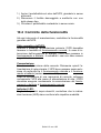
9.4 Batterietest
Während der Betriebsart Normalbetrieb können Sie einen
autom. Batterietest durchführen um Information über Kondition/Alterungszustand der Batterie zu erhalten. Hierzu gibt es
zwei Möglichkeiten:
ON-Taste:
Drücken Sie die ON-Taste bis ein akustisches Signal ertönt
(ca. 1–2 Sek.). Die LEDs „Alarm“, „Line“, „Bypass“, „Inverter“
und „Battery“ beginnen zyklisch zu blinken und signalisieren
somit, dass der Batterietest aktiv ist. Der Batterietest dauert
5 Sekunden.
Analysiert der Test eine defekte Batterie, wird der Test sofort
abgebrochen und auf Normalbetrieb geschaltet.
Seite 31 von 128
Bei defekter Batterie bitte umgehend ONLINE-Hotline anrufen.
HINWEIS:
ONLINE-Hotline: +49 (0) 89 / 2 42 39 90 18
DataWatch-Software:
Weiterhin besteht die Möglichkeit den Batterietest ferngesteuert über die DataWatch-Software zu aktivieren. Hierzu lesen
Sie bitte die separate Bedienungsanleitung auf der DataWatch-CD.
Seite 32 von 128
10. Wartung, Fehler beheben
Die XANTO RT-Serie benötigt im Betrieb nur einen sehr geringen Aufwand an Wartung. Die verwendeten Batterien sind
wartungsfreie Blei-Gel-Akkumulatoren. Ein intelligentes Batteriemanagement überwacht kontinuierlich den Zustand der
Batterien und lädt diese bei Bedarf selbstständig nach.
10.1 Lagerung
Bei Lagerung in gemäßigten Klimazonen sollten die Batterien
alle drei Monate für 1-2 Stunden geladen werden. In Umgebungen mit höheren Temperaturen sollten die Ladeintervalle
auf zwei Monate verkürzt werden.
10.2 Batteriewartung
Die Batterie ist die Schlüsselkomponente des USV-Systems.
Die Lebenserwartung der Batterie ist beschränkt und maßgeblich abhängig von der Umgebungstemperatur und Anzahl der
Lade-/Entladezyklen. Hohe Umgebungstemperatur und Tiefentladung verkürzen die Lebenserwartung erheblich.
1.) Halten Sie die Umgebungstemperatur auf konst. 20°C
2.) Vermeiden Sie häufige, kurze Entladungen
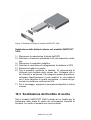
Die XANTO RT 1000 verfügt über eine Hot-Swap-Batterie.
Das heißt, es kann ein Batteriewechsel durch den Anwender
im laufenden Betrieb vorgenommen werden. Ersatzbatterien
erhalten Sie direkt bei der ONLINE USV-Systeme AG oder
jedem autorisierten Fachhändler.
Seite 33 von 128
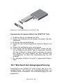
Abbildung 13: Hot-Swap-Batterie bei XANTO RT 1000
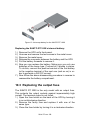
Auswechseln der internen Batterie bei XANTO RT 1000:
1.) Entfernen Sie die Frontblende der USV.
2.) Lösen und entfernen Sie die beiden Schrauben des Metalldeckels.
3.) Entfernen Sie den Metalldeckel.
4.) Lösen Sie den Verbindungsstecker zwischen Batterie und
USV.
5.) Ziehen Sie die Batterie nach vorne heraus.
6.) Jetzt können Sie die Batterien wechseln. Achten Sie darauf nur Batterien des selben Typs zu verwenden. Schalten
Sie alle 3 Blöcke in Reihe. Hierzu verbinden sie jeweils
den Pluspol der einen Batterie mit dem Minuspol der
nachfolgenden, so dass eine Gleichspannung von 36V
entsteht.
7.) Zur Montage verfahren Sie jetzt in umgekehrter Reihenfolge.
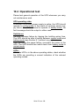
10.3 Wechseln der Ausgangssicherung
Ausschließlich die XANTO RT 3000 verfügt über eine Ausgangssicherung. Sie schützt die Ausgangssteckdosen vor
unzulässig hoher Stromstärke. Der Klemmenausgang ist nicht
abgesichert.
Seite 34 von 128
1.) Öffnen Sie den Sicherungshalter an der Rückseite der
USV. Hierzu drehen Sie ihn gegen den Uhrzeigersinn.
2.) Entfernen Sie die defekte Sicherung und ersetzen Sie sie
gegen eine desselben Typs.
3.) Schließen Sie den Sicherungshalter durch Drehen im Uhrzeigersinn.
10.4 Funktionsüberprüfung
Bitte überprüfen Sie bei jeder Wartung die generelle Funktion
der USV!
USV-Betriebszustand:
Wenn die primäre Spannungsversorgung vorhanden ist, sollte
die USV im Normalbetrieb arbeiten. Liegt ein Ausfall der primären Energieversorgung vor, muss die USV im Batteriebetrieb arbeiten. In beiden Fällen sollte es zu keiner Fehlermeldung kommen.
Umschalten:
Simulieren Sie einen Stromausfall. Schalten Sie hierzu die
primäre Energieversorgung spannungsfrei. Die USV muss
anstandslos zwischen Normalbetrieb und Batteriebetrieb (siehe Kap. 9.1) umschalten.
Nach der Simulation des Stromausfalls, verbinden Sie wieder
den Netzstecker mit der USV. Danach muss die USV zurück
vom Batteriebetrieb in den Normalbetrieb schalten.
LED-Anzeige:
Während der oben beschriebenen Betriebszustände überprüfen Sie bitte ob die LED-Anzeigen mit den jeweiligen Betriebsmodi konform sind.
Seite 35 von 128
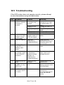
10.5 Fehlersuche
Wenn die USV-Anlage nicht einwandfrei arbeitet, versuchen
Sie bitte zunächst anhand folgender Tabelle das Problem zu
lösen.
Nr.
1
2
3
4
5
6
7
8
Problem
Ursache
Lösung
Kein Einschalten
nach Drücken der
ON-Taste
Taste-Haltedauer
zu kurz
Halten Sie die ON-Taste
gedrückt bis ein akustischen Signale ertönt (12 Sek.)
Batterie mit USV verbinden
Batterie laden, danach
erneut versuchen
ONLINE-Hotline anrufen
ONLINE-Hotline anrufen
Eingangsschutzschalter
drücken
Versorgungsspannung vorhanden,
USV signalisiert
jedoch keine Eingangsspannung
LINE-LED blinkt
ALARM-LED und
Last-LEDs 1-5
blinken, Alarmsignal
Überlast, keine
Ausgangsspannung, kein Bypassbetrieb möglich
Überbrückungszeit
zu kurz
Batteriebetrieb: nur
LED 1 leuchtet
zwischen LEDs 1-5
ALARM-LED +
LED 4 leuchten,
Alarmton
(1x / Sek.)
Keine angeschlossene Batterie
Batteriespannung
zu gering
Batterie defekt
USV-Fehler
Eingangsschutzschalter an der
USV-Rückseite
ausgelöst
Eingangsspannung/-frequenz
außerhalb der
Toleranz
Überlast
Abschalten des
Ausgangs wegen
Bypass-Überlast.
Bypassspannung/
-frequenz außerhalb der Toleranz
Batterie nicht vollständig geladen
Batteriespannung
zu gering
Lüfter-Fehler
Seite 36 von 128
Eingangsspannung/
-frequenz sowie Eingangsschutzschalter
überprüfen. Last manuell ausschalten.
Unkritische Lasten
abschalten
Unkritische Verbraucher
abschalten. Überprüfen
der Eingangsspannung/
-frequenz
Batterie min. 8 Stunden
laden
Last sofort abschalten
um unkontrolliertes
Abschalten zu verhindern
Luftauslass auf Behinderungen überprüfen.
Bei keiner Beeinträchtigung: ONLINE-Hotline
anrufen
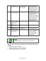
9
ALARM-LED +
LED 1 leuchten,
Alarmton
Keine Ausgangsspannung aufgrund
Kurzschluß im
Ausgang
10
ALARM-LED +
LED 3 leuchten,
Alarmton
Übertemperatur
11
INVERTER-LED
blinkt + ALARMLED leuchtet,
Alarmton
ALARM-LED und
LED 5 leuchten,
Alarmton
ALARM-LED +
LED 2 leuchten,
Alarmton
XANTO RT 3000
Ausgangsbuchse
hat keine Spannung
WechselrichterFehler
12
13
14
USV abschalten und
Last auf Kurzschluß
überprüfen. Wenn Fehler nach Lösen der
Lastverbindung weiterhin vorhanden:
ONLINE-Hotline anrufen.
Überprüfen ob Überlast,
Lüfter blockiert, Umgebungstemperatur über
40°C? Bei normalem
Betriebsverhalten: USV
abschalten, 10 Min.
abkühlen lassen und
wiederholen. Wenn
Fehler nicht behoben:
ONLINE-Hotline anrufen
ONLINE-Hotline anrufen
GleichrichterFehler
ONLINE-Hotline anrufen
Ladegerät-Fehler
ONLINE-Hotline anrufen
Ausgangssicherung defekt
USV abschalten, Ausgangssicherung ersetzen. Last trennen, USV
einschalten und Ausgangsspannung überprüfen. Bei keiner Änderung: ONLINE-Hotline
anrufen.
Tabelle 10: Fehlersuche
HINWEIS:
ONLINE-Hotline: +49 (0) 89 / 2 42 39 90 18
Bei Anruf der Hotline unbedingt nachfolgende Informationen
bereithalten:
• Modell- und Seriennummer
• Kauf- und Installationsdatum
• Ausführliche Beschreibung des Problems
Seite 37 von 128
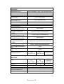
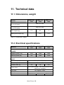
11. Technische Daten
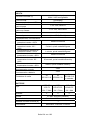
11.1 Abmessungen, Gewicht
MODELL
XANTO RT
1000
XANTO RT
2000
Abmessungen USV,
B x H x T (mm)
440 x 87 x 400
Abmessungen Batteriepaket, B x H x T (mm)
440 x 87 x 400
Gewicht USV (kg)
Gewicht Batteriepaket (kg)
XANTO RT
3000
17,5
8,6
9
-
20,5
21,5
Tabelle 11: Abmessungen, Gewicht
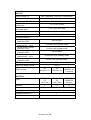
11.2 Elektrische Spezifikationen
XANTO RT
1000
XANTO RT
2000
XANTO RT
3000
Scheinleistung (VA)
1000
2000
3000
Wirkleistung (W)
700
1400
2100
MODELL
LEISTUNG
EINGANG
Nennspannung (V)
230V (186 – 288VAC)
Frequenz (Hz)
Stromstärke, max. (A)
Leistungsfaktor
Kaltstart
50Hz +/- 10%
3,8
7,8
>0,99 (Nennspannung, 100% Wirklast,
vollständig geladene Batterie)
ja, voreingestellt = 50Hz
Eingangsschutzart
Eingangsstecker
10,7
Schalter
IEC320 C14
Seite 38 von 128
IEC320 C14
IEC320 C20
AUSGANG
Nennspannung (V)
220V (standard), 230V / 240V konfigurierbar
Wellenform
Sinus
Frequenz, USV-Betrieb
Verzerrungsfaktor,
lineare Last
Verzerrungsfaktor,
nicht-lineare Last
Scheitelfaktor
50Hz +/- 0,2%
< 2% THD, R-Last
< 5% THD, RCD-Last
3:1
Leistungsfaktor
Überlastverhalten
Normalbetrieb, Wechselrichter-Überlast <105%
Normalbetrieb, Wechselrichter-Überlast 105 125%
Normalbetrieb, Wechselrichter-Überlast >125%
Batteriebetrieb, Wechselrichter-Überlast <105%
Batteriebetrieb, Wechselrichter-Überlast 105 125%
Batteriebetrieb, Wechselrichter-Überlast >125%
Wirkungsgrad, Normalbetrieb
Wirkungsgrad, Batteriebetrieb
Ausgangsbuchse
typ. 0,7 (0,65 - 1,0)
kein Einfluss
5 Minuten, danach Bypassbetrieb
1 Minute, danach Bypassbetrieb
kein Einfluss
30 Sekunden, danach Bereitschaftsbetrieb
250ms, danach Bereitschaftsbetrieb
>88%
>83%
4x
IEC320 C13
4x
IEC320 C13
2x
IEC320 C13
+ Klemme
CSB GP 1272
F2
12V / 7,2Ah
CSB GP1272
F2
12V / 7,2Ah
CSB HR
1234W F2
12V / 9Ah
3
6
6
BATTERIE
Typ
Anzahl
Lebensdauer
3-5 Jahre gemäß EUROBAT
Ladezeit
5 Stunden bis 90% Kapazität
Ladestromstärke (A)
Batterietest
1
Automatisch, manuell, ferngesteuert
Seite 39 von 128
ÜBERBRÜCKUNGSZEIT
Standard (interne Batterie)
Minuten (bei 50% / 100% Wirklast)
17 / 6
-
-
+ 1 Batteriepaket
-
18 / 6
12 / 5
+ 2 Batteriepakete
-
51 / 19
31 / 16
+ 3 Batteriepakete
-
93 / 36
55 / 26
+ 4 Batteriepakete
-
121 / 53
73 / 40
INTERFACE, SOFTWARE
RS-232-Schnittstelle
Potentialfreie Kontakte
(Batteriekapazität
hoch/niedrig, shutdown)
Netzwerkmanagementkarte,
basic
Netzwerkmanagementkarte,
professionell
USB-Karte
Ja
Ja
option
option
option
DataWatch-Software
inklusive
Tabelle 12: Elektrische Spezifikationen
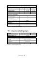
11.3 Umgebungsbedingungen
Betriebstemperatur (°C)
XANTO RT
2000
0 - 40
Lagertemperatur (°C)
-25 bis +55
MODELL
Relative Luftfeuchtigkeit (%)
Kühlung
Einsatzhöhe
Betriebsgeräusch (dB)
XANTO RT
1000
XANTO RT
3000
5 - 95%, nicht kondensierend
aktive Kühlung, 2 interne Lüfter, Lufteinlass
an der Vorderseite
1500 - 3000m, Leistungsminderung von 1% je
weitere 100m
43
45
45
Tabelle 13: Umgebungsbedingungen
Seite 40 von 128
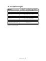
11.4 Zertifizierungen
MODELL
XANTO RT
1000
Schutzart (IP)
Sicherheit
XANTO RT
2000
21
XANTO RT
3000
EN 50082-1
ESD
IEC 61000-4-2, Level 3
Störanfälligkeit
IEC 61000-4-3, Level 3
Umschaltzeit
IEC 61000-4-4, Level 4
Stromstoß
IEC 61000-4-5, Level 4
Oberschwingungen
Elektromagn. Verträglichkeit
EN 61000-3-2, EN 61000-3-3
EN 50091-2 Class B
Niederspannungsrichtlinie
EN 62040-1-1
CE-marked
Tabelle 14: Zertifizierungen
Seite 41 von 128
12. Garantie
Die ONLINE USV-Systeme AG (ONLINE) gewährleistet, dass dieses Produkt
für die Dauer von zwei Jahren ab Kaufdatum frei von Material- und Fertigungsfehlern ist. Die Verpflichtung von ONLINE gemäß dieser Garantie ist auf
die Reparatur oder den Ersatz (Entscheidung trifft ONLINE) jeglicher defekter
Produkte begrenzt. Bevor unter die Garantie fallende Wartungsleistungen in
Anspruch genommen werden können, muss beim Kundendienst eine Warenrücknahmenummer (Returned Material Authorization---RMA) angefordert
werden. Produkte müssen als vom Absender bezahlte Sendung zurückgeschickt werden, und eine kurze Beschreibung des aufgetretenen Problems
sowie einen Nachweis von Ort und Datum des Kaufs enthalten. Diese Garantie gilt nicht für Geräte, die durch Unfall, Fahrlässigkeit oder Missbrauch beschädigt, oder in irgendeiner Weise verändert oder modifiziert wurden.
VON HIERIN VORGESEHENEN AUSNAHMEN ABGESEHEN, ÜBERNIMMT
ONLINE KEINERLEI AUSDRÜCKLICHE ODER STILLSCHWEIGENDE GARANTIE, EINSCHLIESSLICH DER ZUSICHERUNG HANDELSÜBLICHER
QUALITÄT ODER DER EIGNUNG FÜR EINEN BESTIMMTEN ZWECK. In
einigen Gerichtsbarkeiten ist die Einschränkung oder der Ausschluss stillschweigender Garantien untersagt, so dass die vorstehenden Einschränkungen oder Ausschlüsse für den Käufer möglicherweise nicht gelten.
VON HIERIN VORGESEHENEN AUSNAHMEN ABGESEHEN, HAFTET
ONLINE UNTER KEINEN UMSTÄNDEN FÜR UNMITTELBARE, MITTELBARE, BESONDERE, NEBEN- ODER FOLGESCHÄDEN, DIE INFOLGE DER
BENUTZUNG DIESES PRODUKTS ENTSTEHEN, SELBST WENN ONLINE
ÜBER DIE MÖGLICHKEIT SOLCHER SCHÄDEN IN KENNTNIS GESETZT
WURDE. ONLINE haftet insbesondere nicht für Kosten jeglicher Art, wie z.B.
entgangene Gewinne oder Einkünfte, den Verlust von Geräten, Verlust der
Nutzung eines Gerätes, Verlust von Software oder Daten, Ersatzkosten,
Ansprüche von Dritten oder andere Kosten.
Der Inhalt unterliegt dem Urheberrecht Copyright © 2006 der ONLINE USVSysteme AG. Alle Rechte vorbehalten. Vervielfältigung im Ganzen oder in
Teilen ist ohne Erlaubnis nicht gestattet.
Seite 42 von 128
User Manual
ONLINE XANTO RT-Series
Germany
Italy
Switzerland
ONLINE USV-Systeme AG
Dreimühlenstraße 4
D-80469 München
Phone +49 (89) 2423990-10
Fax +49 (89) 2423990-20
www.online-usv.de
ONLINE UPS-Systems S.r.l.
Via Edison 12
I-20058 Villasanta (Milano)
Phone +39 (039) 2051444
Fax +39 (039) 2051435
www.online-ups.it
ONLINE USV-Systeme AG
Eigenheimstraße 11
CH-8304 Wallisellen (Zürich)
Phone +41 (44) 9452829
Fax +41 (44) 9453288
www.online-usv.ch
Seite 43 von 128
Seite 44 von 128
1. Contents
1.
Contents ........................................................................45
2.
List of figures................................................................47
3.
List of tables .................................................................48
4.
Introduction...................................................................49
5.
Safety instructions .......................................................50
6.
Product description......................................................53
6.1
6.2
6.2.1
6.2.2
7.
Principle of operation...................................................61
7.1
7.2
7.2.1
7.2.2
7.2.3
8.
Power electronics ....................................................61
Interface connections ..............................................62
RS-232 protocol.......................................................63
Dry contacts ............................................................63
Slot for optional interface cards ...............................64
Installation.....................................................................65
8.1
8.1.1
8.1.2
8.2
8.3
9.
Features ..................................................................53
System components ................................................53
Control unit ..............................................................54
Batterypack .............................................................59
Tower installation.....................................................66
UPS single tower installation ...................................66
UPS plus Batterypack installation ............................67
Rack installation ......................................................68
Software installation ................................................68
Operation.......................................................................69
9.1
9.2
9.2.1
9.2.2
9.3
9.3.1
9.3.2
9.3.3
9.4
Operating modes .....................................................69
Switching on ............................................................70
Normal start (input voltage present)........................70
Cold start (power failure) .........................................71
Switching off ............................................................72
Switching off in normal mode...................................72
Switching off in battery mode...................................72
Switching off in bypass mode ..................................72
Battery test ..............................................................72
Seite 45 von 128
10. Maintenance, troubleshooting.....................................74
10.1
10.2
10.3
10.4
10.5
Storage....................................................................74
Battery maintenance................................................74
Replacing the output fuse ........................................75
Operational test .......................................................76
Troubleshooting.......................................................77
11. Technical data...............................................................79
11.1
11.2
11.3
11.4
Dimensions, weight .................................................79
Electrical specifications............................................79
Ambient conditions ..................................................81
Certifications............................................................82
12. Warranty ........................................................................83
Seite 46 von 128
2. List of figures
Figure 1: XANTO RT series front panel
54
Figure 2: Control panel
55
Figure 3: XANTO RT 1000 back panel
58
Figure 4: XANTO RT 2000 back panel
59
Figure 5: XANTO RT 3000 back panel
59
Figure 6: Front view of XANTO RT Batterypack
60
Figure 7: Rear view of XANTO RT Batterypack
60
Figure 8: Block diagram
61
Figure 9: Baseplate for tower installation
66
Figure 10: Positioning the UPS
66
Figure 11: Baseplate with extension
67
Figure 12: Connecting the Batteriepacks
67
Figure 13: Hot-swap-battery for the XANTO RT 1000
75
Seite 47 von 128
3. List of tables
Table 1: Operating controls
56
Table 2: Indicators
56
Table 3: Fault codes (LED and audible signal combinations)
57
Table 4: Battery types
59
Table 5: Autonomy time with additional Batteriepacks
(BP = Batterypack)
60
Table 6: RS-232 interface pin assignment
63
Table 7: Interface pin assignment (DB9-socket)
64
Table 8: Overview of interface accessories
64
Table 9: Scope of supply
65
Table 10: Troubleshooting
78
Table 11: Dimensions, weight
79
Table 12: Electrical specifications
81
Table 13: Ambient conditions
81
Table 14: Certifications
82
Seite 48 von 128
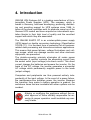
4. Introduction
ONLINE USV-Systeme AG is a leading manufacturer of Uninterruptible Power Supplies (UPS). The company, which is
based in Germany, has been developing, producing, distributing and providing support for UPS systems since 1988. In
terms of the sheer quantities sold, its products come top of the
German UPS market and have acquired an international reputation thanks to their high level of quality and the excellent
support with which they are associated.
The ONLINE XANTO RT is an uninterruptible power supply
(UPS) based on double conversion technology (Classification
VFI-SS-111). It is the ideal form of protection for all businessrelated data processing and telecommunications applications.
This means that power failures, voltage fluctuations and voltage surges, which can damage servers and other electronic
equipment, are prevented.
The double-converter principle eliminates all mains power
disturbances. A rectifier converts the alternating current from
the socket outlet (input voltage) into direct current. This direct
current charges the batteries and powers the inverter. On the
basis of this DC voltage, the inverter generates a sinusoidal
AC voltage which permanently supplies power to the loads
(output voltage).
Computers and peripherals are thus powered entirely independently of the input voltage. In the event of a power failure,
the maintenance-free batteries power the inverter. Because
the transition from mains to battery operation is gradual, the
switchover times that are inevitable with other systems can be
avoided.
Altering or modifying this appliance without the explicit approval of those officially responsible for ensuring its proper operation could invalidate any warranty claims.
Seite 49 von 128
5. Safety instructions
BEFORE INSTALLING THE UNIT AND STARTING IT UP,
PLEASE READ (AND OBSERVE!) THE USER MANUAL
AND SAFETY INSTRUCTIONS
Transport
• Please transport the UPS system only in the original packaging (to protect against shock and impact).
Set-up
Because of its weight, the UPS needs to be installed by two
people.
This appliance is designed for installation inside a temperature-controlled area that is free from conductive and contaminated substances. For information about the necessary ambient conditions, please refer to Section 11.3.
• Condensation may occur if the UPS system is moved directly from a cold to a warm environment. The UPS system
must be absolutely dry before being started up for the first
time. Please allow an acclimatisation time of at least two
hours.
• Do not install the UPS system near water or in damp environments.
• Do not install the UPS system where it would be exposed
to direct sunlight or near heat.
• Do not block off ventilation openings in the UPS system’s
housing.
Seite 50 von 128
Connection / Electrical safety
• Never work alone in dangerous conditions.
• Always ensure that plugs, socket outlets and input cables
are in good working order.
• Connect the UPS system only to an earthed socket outlet.
• Ensure maximum current draw and that the building wiring
is adequately fused.
• The building wiring socket outlet (with earthing contact)
must be easily accessible and close to the UPS system.
• Only use VDE-tested and CE-marked connecting cables.
• As specified by the EMC Directive, the output cable connected to the UPS must not exceed a length of 10m.
• Do not connect household appliances such as hair dryers
to UPS output sockets.
• Do not connect any appliances to UPS output sockets
which will overload the UPS (e.g. laser printers).
• Lay cables in such a way that no one can step on or trip
over them.
Operation
• Do not disconnect the mains cable from the UPS system or
the building wiring socket outlet (with earthing contact) during operation, since this would cancel the protective
earthing of the UPS system and of all connected loads.
• The UPS system features its own, internal current source
(batteries). The UPS output sockets may be electrically live
even if the UPS system is not connected to the socket outlet / the building wiring supply.
• In order to fully disconnect the UPS system, first press and
hold down the OFF button for at least 2 seconds, then disconnect the mains lead.
• Ensure that no fluids or other foreign objects can enter the
UPS system.
Seite 51 von 128
Maintenance, servicing and faults
• The UPS system operates with hazardous voltages. Repairs may only be carried out by qualified maintenance
personnel.
• The battery is the only component of this unit that should
be replaced by the user.
• Caution – risk of electric shock. Even after the unit is disconnected from the mains power supply (outlet socket),
components inside the UPS system are still connected to
the battery and are still electrically live and dangerous. Before carrying out any kind of servicing and / or maintenance, disconnect the batteries and verify that no current is
present.
• Only persons adequately familiar with batteries and with
the required precautionary measures may replace batteries
and supervise operations. Unauthorised persons must be
kept well away from the batteries.
• Caution – risk of electric shock. The battery circuit is not
isolated from the input voltage. Hazardous voltages may
occur between the battery terminals and the earth.
• Batteries may cause electric shock and have a high shortcircuit current. Please take the precautionary measures
specified below and any other measures necessary when
working with batteries:
- Remove wristwatches, rings and other metal objects.
- Only use tools with insulated grips and handles.
• When replacing batteries, install the same number and
same type of batteries.
• Do not attempt to dispose of batteries by burning them.
This could cause the batteries to explode.
• Do not open or destroy batteries. Escaping electrolyte can
cause injury to the skin and eyes. It may be toxic.
• Please replace the fuse only by a fuse of the same type
and of the same amperage in order to avoid fire hazards.
• Do not dismantle the UPS system.
Seite 52 von 128
6. Product description
XANTO RT is an intelligent ONLINE UPS (Quality Class 1,
Classification VFI-SS-111) providing maximum system availability. It supplies any sensitive appliances that are connected
with perfect sinusoidal AC voltage, thereby protecting them
against power failures and voltage fluctuations.
The special product design makes for a wide range of possible
applications. Depending on customer requirements, it can be
installed as a tower / floor-mounted unit or even as part of a
rack. It is ideal for applications involving limited floor space
such as in the case of telecommunications installations, server
rooms, etc.
6.1 Features
•
•
•
•
•
Installation height of just 2 height units.
Hot-swap-battery.
XANTO RT 3000 with output terminal connection.
Extremely high performance, efficiency >88%.
Very low noise emissions (max. 43dB) thanks to use of
controlled fans.
• High degree of system availability, self-monitoring and fault
diagnosis thanks to advanced DSP technology.
• High input voltage tolerance; output impervious to input
voltage disturbances. Suitable for any area of application
where a constant power supply cannot be guaranteed.
• High input frequency tolerance. Ideal for generator-based
operation.
6.2 System components
XANTO RT consists of two basic elements: the control unit
and the Batterypack.
The former is responsible for power transfer (a bit like a car
engine) and supplies the output voltage for the load. In addition, the control unit monitors and charges the battery. In the
Seite 53 von 128
event of a power failure, the Batterypack supplies the UPS
with DC voltage (a bit like a car’s fuel tank).
6.2.1 Control unit
Three different models of the control unit are available:
• 1kVA with internal battery, autonomy time cannot be extended.
• 2kVA control unit without internal battery. External Batterypack required for operation. Autonomy time can be extended by operating several Batteriepacks in parallel.
• 3kVA control unit without internal battery. External Batterypack required for operation. Autonomy time can be extended by operating several Batteriepacks in parallel.
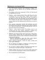
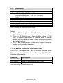
6.2.1.1 Front panel:
The front panel is the same on all the control units. Various
indicators and operating controls are available here.
The operating controls consist of the ON- and OFF-buttons
and the LED indicators.
Figure 1: Frontpanel of XANTO RT series
Seite 54 von 128
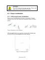
6.2.1.2 Indicators and operating controls:
Figure 2: Control panel
Operating controls:
Button
ON-button
Function
ON / Alarm-OFF-button:
The ON / Alarm-OFF-button can be used to
perform three functions:
1.) Switch on UPS / inverter:
Press and hold down the ON-button
until you hear an audible signal
(approx. 1-2 secs.). The USP will
switch to normal mode.
2.) Alarm ON / OFF (in battery mode):
An audible signal is emitted every 3
seconds in battery mode. Press and
hold down the ON-button until you hear
an audible signal (approx. 1-2 secs.).
This will deactivate the intermittent signal. To reactivate it, press and hold
down the ON-button again until you
hear an audible signal (approx. 1-2
secs.).
Seite 55 von 128
3.)
OFF-button
Activate battery test function (in normal
mode):
Press and hold down the ON-button
until you hear an audible signal
(approx. 1–2 secs.)
The OFF-button performs 2 functions:
1.) Switch off inverter:
To switch off the inverter in normal- or
battery-mode, press and hold down the
OFF-button (for approx. 2 secs.). The
output sockets are no longer live.
2.) Standby-mode:
In bypass-mode, press and hold down
the OFF-button (for approx. 1-2 secs.).
The UPS will disconnect the voltage
from the output.
Table 1: Operating controls
Indicators:
The following table explains what the LEDs mean:
BATTERY-LED
(green)
INVERTER-LED
(green)
BYPASS-LED
(green)
LINE-LED
(green)
ALARM-LED (red)
UPS-operation / battery-operation
and battery voltage within tolerances (continuous light).
Flashing LED: battery faulty or
charging voltage too high.
Normal-operation / inverteroperation (continuous light).
Flashing LED: inverter faulty.
Bypass-mode.
CAUTION: The load does not benefit from battery-backed power supply!!!
Mains voltage within tolerances.
In the event of a power failure, this
LED will go off.
Fault, e.g. overload.
Table 2: Indicators
Seite 56 von 128
Specific LED and audible signal combinations indicate certain
statuses, as shown below (see also Section 10.5):
Normal mode
(load)
Battery mode (capacity)
Audible
signal
0 – 25%
z
26 – 50%
z
z
51 – 75%
z
z
z
76 – 100%
z
z
z
z
101 – 105%
z
z
z
z
> 105%
z
z
z
z
Battery
Inverter
None
z
z
None
z
z
None
z
z
z
None
z
z
z
2x / sec.
z
z
z
z
1x / 3 sec.
z
z
z
z
z
1x / 3 sec.
z
z
z
z
z
z
1x / 3 sec.
z
z
z
z
z
z
1x / 3 sec.
z
Charger fault
z
Overtemperature
z
z
Inverter fault
z
}
}
Continuous
z
}
}
Continuous
z
}
}
Continuous
z
}
}
z
}
}
z
}
}
z
}
}
Overload
z
z
z
z
z
Battery faulty (normal
mode)
Battery fault
(standby mode)
}
}
}
}
}
z
}
}
}
}
}
}
No battery
}
}
}
}
}
z
z = ON
Bypass
z
z
Rectifier fault
Line
z
1x / sec.
Short circuit
Fan fault
Alarm
None
z
51 – 75%
z
z
z
26 – 50%
>96%
z
z
0 – 25%
76 – 95%
5
4
3
2
LED combination
1
Mode
} = Dependent upon other operating status
Table 3: Fault codes (LED and audible signal combinations)
Seite 57 von 128
}
}
1x / sec.
Continuous
Ï
Continuous
Continuous
z
}
Ï
None
Ï
None
Ï 6x
Ï = Flashing
CAUTION:
LED 5 = yellow,
ALARM LED = red,
All other LEDs = green
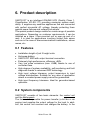
6.2.1.3 Back panel:
The various control units do not share the same back panel.
The back panel features the following:
• Input socket in the form of an inlet connector for nonheating appliances (male).
• Overcurrent protective device.
• Output sockets in the form of 10A outlet sockets for nonheating appliances, plus terminal block in the case of the
3kVA control unit.
• Connection socket for external Batterypack (does not apply
to 1kVA control unit).
• DB9-socket (male) for RS-232 communication and dry
contacts.
• Slot for optional interface cards (basic SNMP- / network
management card, professional SNMP- / network management card, USB-adaptor).
Figure 3: XANTO RT 1000 back panel
Seite 58 von 128
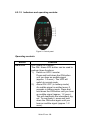
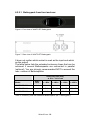
Figure 4: XANTO RT 2000 back panel
Figure 5: XANTO RT 3000 back panel
6.2.2 Batterypack
The Batterypack comes in two different versions. However,
both versions are identical in terms of dimensions and appearance (front and rear):
Designation
Properties
XANTO RT 2000 Batterypack
6x 12V / 7,2Ah battery
XANTO RT 3000 Batterypack
6x 12V / 9,0Ah battery
Table 4: Battery types
Seite 59 von 128
6.2.2.1 Batterypack from front and rear:
Figure 6: Front view of XANTO RT Batterypack
Figure 7: Rear view of XANTO RT Batterypack
It does not matter which socket is used as the input and which
as the output!
The table below lists the extended autonomy times that can be
achieved if several Batteriepacks are connected in parallel
(optional). You are strongly recommended NOT to exceed the
max. number of Batteriepacks:
Autonomy time (min.)
at 50% / 100% load
Model
Standard
+ 1 BPs
+ 2 BPs
+ 3 BPs
+ 4 BPs
XANTO RT 1000
18 / 6
-
-
-
-
XANTO RT 2000
-
17 / 6
52 / 20
94 / 37
122 / 54
XANTO RT 3000
-
12 / 5
37 / 16
55 / 26
78 / 40
Table 5: Autonomy time with additional Batteriepacks (BP = Batterypack)
Seite 60 von 128
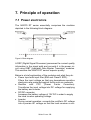
7. Principle of operation
7.1 Power electronics
The XANTO RT series essentially comprises the modules
depicted in the following block diagram:
Figure 8: Block diagram
A DSP (Digital Signal Processor) processes the current quality
information in the signal path and converts it in the power circuit using IGBT (Insulated Gate Bipolar Transistor) modules.
This ensures the XANTO RT series’ superior quality.
Below is a brief explanation of the modules and what they do:
• Power input with input filter (EMI and Class D SPD):
Filters the input voltage so that any downstream sensitive
electronics are protected against faults such as overloads.
• Rectifier
with
PFC
(Power
Factor
Correction):
Transforms the input voltage into DC voltage for supplying
the battery and inverter.
• DC/DC converter:
Increases the battery voltage of 12V DC in order to supply
the ideal inverter operating voltage.
• Inverter:
During normal operation: converts the rectifier’s DC voltage
into a precise AC voltage so that the load receives a con-
Seite 61 von 128
stant 230V, 50Hz power supply. During battery operation:
inverter is supplied with power from the battery.
• Bypass:
In the event of a fault (e.g. overtemperature or overload),
the bypass module protects the internal electronics against
irreparable damage. In the event of a fault, the load supply
is automatically switched to bypass mode and the loads are
supplied with power from the building’s normal mains supply WITHOUT battery back-up. This operating state is indicated on the front panel and in the form of information via
the software.
• Charger:
During charging, the internal charger supplies the batteries
with a constant current of 1A.
• Battery / accumulator:
Maintenance-free, sealed lead gel accumulator.
7.2 Interface connections
With the XANTO RT series, the back panel of the UPS system
is equipped with a DB9-port and a slot for optional interface
cards. Computers can be connected to either of them.
The DB9-socket supports communication on the basis of the
RS-232 protocol as well as the use of dry contacts.
These connections enable the following:
• Monitoring of the UPS system,
• Monitoring of the input voltage,
• Automatic data back-up,
• Computer shutdown and
• UPS system shutdown.
These functions are supported by the DataWatch software,
which is included in the scope of supply.
Seite 62 von 128
7.2.1 RS-232 protocol
Pin
2
3
5
TxD
RxD
GND
Gesendete Daten
Empfangene Daten
Masse
Transmitted data
Received data
Ground
Table 6: RS-232 interface pin assignment
7.2.2 Dry contacts
Pin description
Floating outputs (pins 1 & 7, 8 & 9) *
Floating input (pins 4 & 5) *
* Max. voltage / current at pins 1, 4, 5, 7, 8 and 9 is 30V DC, 10mA
Seite 63 von 128
Pin
1
2
3
4
5
6
7
8
9
Description
Battery flat (open collector)
UPS TxD (typ. RS-232 level)
UPS RxD (typ. RS-232 level)
Remote inverter OFF 5-12V DC, 10-24mA
(in battery mode)
GND
Battery flat (open emitter)
Battery mode (open emitter)
Battery mode (open collector)
Table 7: Interface pin assignment (DB9-socket)
Notes:
1.) Pins 1 & 7: floating output. Open if battery voltage normal.
Closed if battery voltage low.
2.) Pins 4 & 5: floating input. If an auxiliary voltage (5-12V
DC) is applied for at least 20 seconds when in battery
mode, the UPS will shut down. These pins do not perform
any other function.
3.) Pins 8 & 9: floating output. Open during normal operation,
closed during battery operation.
7.2.3 Slot for optional interface cards
XANTO RT is equipped with a slot for optional interface cards.
This ensures compatibility with the following ONLINE USVSysteme AG products:
Order no.
DW5SNMP30
DW7SNMP30
PHXUSB
Description
Network management card, professional
Network management card, basic
USB-adaptor
Table 8: Overview of interface accessories
Seite 64 von 128
8. Installation
Description
Quantity
XANTO RT 1000
XANTO RT 2000
XANTO RT 3000
XANTO RT 2000 Batterypack
XANTO RT 3000 Batterypack
1.) Inspect the packaging carton and its contents to ensure
that nothing is missing and to check for any damage.
Please inform the transport agency immediately should
you find signs of damage. Please keep the packaging in a
safe place for future use.
19“ mounting angle
2
X
X
X
X
X
Baseplate for tower installation
2
X
X
X
-
-
Baseplate, extension
2
-
-
-
X
X
10A non-heating appliance extension
2
X
X
X
-
-
16A mains cable
1
-
-
X
-
-
Battery cable
1
-
-
-
X
X
Interface cable
1
X
X
X
-
-
Software DataWatch
1
X
X
X
-
-
Operating instructions
1
X
X
X
-
-
Table 9: Scope of supply
2.) The UPS is cooled by means of forced ventilation using
internal fans. Please ensure a min. clearance of 30cm to
the rear of the UPS.
3.) Connect the UPS system to a building wiring socket outlet
(with earthing contact) using a VDE-tested and CEmarked mains cable. To connect the XANTO RT 3000
please use the mains cable supplied with the unit.
Seite 65 von 128
CAUTION:
The UPS output sockets are now live. This is indicated by the LINE and BYPASS LEDs.
8.1 Tower installation
8.1.1 UPS single tower installation
Please use the baseplates included in the scope of supply.
Remove them from the carton and assemble them as shown
below.
Figure 9: Baseplate for tower installation
After assembling the two separate components, please position the UPS on the baseplates as shown below.
Figure 10: Positioning the UPS
Seite 66 von 128
8.1.2 UPS plus Batterypack installation
Additional Batteriepacks are available for all UPS systems in
the XANTO RT series (except for the XANTO RT 1000).
To install the UPS and Batterypack, please proceed in the
manner described above under 8.1.1.
For maximum stability, please use the baseplate extension
(supplied with Batterypack). The size will depend on the number of additional Batteriepacks used.
Figure 11: Baseplate with extension
Use the battery cable (supplied with Batterypack) to connect
the UPS to the Batterypack:
1.) Disconnect the UPS system
from the mains power supply
and the loads from the UPS
system.
2.) Connect one end of the battery cable to the socket on
the back of the UPS for connecting the external battery
and the other end to any
socket on the back of the battery pack.
Figure 12: Connecting the Batteriepacks
NOTE:
If an external Batterypack is used, the charging
time increases to 24 hours (or 48 hours in the
case of two Batteriepacks), assuming that the
battery has been completely discharged.
Seite 67 von 128
CAUTION:
The XANTO RT 2000 and XANTO RT 3000 do
not contain internal batteries. To ensure proper
operation, the UPS must be connected to a Batterypack.
8.2 Rack installation
If installing the UPS inside a rack, you must use a standard
19“ rack with a depth of at least 400mm. To ensure optimum
weight distribution, please use our optional mounting rails
(order no. “Rack-Kit”) or alternatively use mounting rails specific to the cabinet manufacturer.
1.) Use the mounting angle included in the scope of supply.
2.) Remove the M4x8 screws from both side panels of the
UPS (4 on each side).
3.) Attach the mounting angle using the screws you have just
removed.
4.) Mount the UPS in the rack and secure it.
8.3 Software installation
To install the DataWatch shutdown, management and monitoring software, please follow the separate instructions included
on the CD.
Seite 68 von 128
9. Operation
1.) Charge the batteries fully by connecting the UPS to the
mains supply for 1-2 hours. Although you can use the UPS
immediately without charging, the autonomy time in the
event of a mains failure may be shorter than the rated
value indicated.
2.) Make sure that the UPS output voltage is the same as that
of your computer (usually 230V). You can set the UPS
output voltage with the software.
3.) Connect your computer to the UPS output socket using
the 10A appliance extension cable for non-heating appliances supplied with the product.
CAUTION:
Do not connect any appliances to UPS output
sockets which will overload the UPS (e.g. laser
printers). Do not connect any household appliances to the UPS.
9.1 Operating modes
XANTO RT features three operating modes:
1.) Normal mode:
The load is supplied with power by the inverter as long as the
power supply voltage remains within the defined tolerance.
Power is supplied to the inverter by the rectifier.
In this operating state, the “LINE” and “INVERTER” LEDs light
up.
Seite 69 von 128
2.) Bypass mode:
Bypass mode protects the internal electronics by preventing
them sustaining irreparable damage as a result of impermissibly high current or overtemperature.
In normal mode, the UPS switches to this mode automatically
in the event of an inverter fault, overtemperature, etc. In bypass mode, the load is supplied with power directly by the
input voltage.
In bypass mode, no battery back-up protection is afforded!
The battery continues to be charged. In this operating state,
the “LINE” and “BYPASS” LEDs light up.
3.) Battery mode:
If, in normal mode, the input voltage strays outside the defined
voltage and / or frequency tolerances, or in the event of an
absolute power failure, the UPS will switch to battery mode
automatically and without interruption of supply. The rectifier
and charger will be rendered inactive.
In battery mode, the “BATTERY” and “INVERTER” LEDs light
up.
9.2 Switching on
There are two ways of switching on the UPS:
9.2.1 Normal start
(input voltage present)
Connect the UPS to a building wiring socket outlet (with
earthing contact) and press the ON-button until you hear an
audible signal (approx. 1–2 seconds). The UPS will start a
self-test at this point and will switch to normal mode once it
has completed this test successfully.
Seite 70 von 128
The “LINE”, “INVERTER” and “LOAD/BATTERY-CAPACITY”
LEDs will light up to indicate that the UPS is functioning correctly.
Test that the UPS system is operating correctly. To do this,
disconnect the input of the UPS system from the supply by
tripping the building wiring fuse.
CAUTION:
The UPS features a self-start function. If active,
the inverter will start automatically as soon as the
battery has been fully discharged and after the
return of the input voltage. The self-start function
can be deactivated by DataWatch-Software.
9.2.2 Cold start (power failure)
If no input voltage is present, the UPS can also be started
independently via the battery. Press the ON-button until you
hear an audible signal (approx. 1–2 secs.). This will switch the
inverter on and the UPS will operate in battery mode.
CAUTION:
The output sockets of the UPS system may still
be electrically live even if the mains supply has
been disconnected or the mains cable has been
disconnected.
Seite 71 von 128
9.3 Switching off
The UPS can be switched off in all three operating modes.
9.3.1 Switching off in normal mode
Press and hold down the OFF-button until you hear an audible
signal (1-2 secs.). The inverter will switch off and the UPS will
switch to standby mode. Power stops being supplied to the
load.
To shut the UPS down completely, disconnect the mains cable. The fans will continue to run for a little while and then the
UPS will switch off completely.
9.3.2 Switching off in battery mode
Press the OFF-button until you hear an audible signal (approx.
1–2 secs.). The UPS switches off and cuts the power supply to
the load.
9.3.3 Switching off in bypass mode
Press the OFF-button until you hear an audible signal (approx.
1–2 secs.). The UPS switches to standby mode and cuts the
power supply to the load. To shut the UPS down completely,
disconnect the mains cable. The fans will continue to run for a
little while and then the UPS will switch off completely.
9.4 Battery test
In normal mode, you can run an automatic battery test, which
provides information about the battery’s condition / deterioration. There are two ways of doing this:
Seite 72 von 128
ON-button:
Press the ON-button until you hear an audible signal (approx.
1–2 secs.). The “Alarm”, “Line”, “Bypass”, “Inverter” and “Battery” LEDs will commence a flashing cycle to indicate that the
battery test is in progress. The battery test lasts for 5 seconds.
If the test detects a faulty battery, the test will be interrupted
immediately and normal mode will be resumed.
In the event of a faulty battery, please call the ONLINE-Hotline
at your earliest convenience.
NOTE:
ONLINE-Hotline: +49 (0) 89 / 2 42 39 90 18
DataWatch software:
You can also run a remote battery test via the DataWatch
software. For information concerning this option, please refer
to the separate instructions on the DataWatch CD.
Seite 73 von 128
10. Maintenance,
troubleshooting
The XANTO RT series requires very little maintenance in the
course of operation. It uses maintenance-free lead gel accumulators and features an intelligent battery management system, which monitors the battery status constantly and charges
the batteries automatically when necessary.
10.1 Storage
If the batteries are to be stored in temperate climatic zones,
they should be charged every three months for 1-2 hours. You
should shorten the charging intervals to two months at locations subject to high temperatures.
10.2 Battery maintenance
The battery is the key component of the UPS system. The
battery has a limited life expectancy, which is heavily dependent on the ambient temperature and the number of charging/discharging cycles. If the battery is used in high ambient
temperatures and discharged totally, its life expectancy will be
shortened considerably.
1.) Maintain a constant ambient temperature of 20°C
2.) Avoid short and frequent discharges
The XANTO RT 1000
which means that the
while the system is in
available from ONLINE
authorised dealer.
is equipped with a hot swap battery,
battery can be replaced by the user
operation. Replacement batteries are
USV-Systeme AG directly or from any
Seite 74 von 128
Figure 13: Hot-swap-battery for the XANTO RT 1000
Replacing the XANTO RT 1000’s internal battery:
1.)
2.)
3.)
4.)
5.)
6.)
Remove the UPS unit’s front panel.
Unscrew and remove the two screws in the metal cover.
Remove the metal cover.
Release the connector between the battery and the UPS.
Pull the battery forwards to remove it.
Now you can replace the battery. Make sure you only use
batteries of the same type. Connect all 3 blocks in series.
To do this, connect the positive terminal of the first battery
to the negative terminal of the next one (and so on) in order to generate a 36V DC current.
7.) Now follow the above disassembly procedure in reverse to
reassemble the battery compartment.
10.3 Replacing the output fuse
The XANTO RT 3000 is the only model with an output fuse.
This protects the output sockets against impermissibly high
current. The terminal output is not fused.
1.) Open the fuse holder on the back of the UPS by turning it
in an anticlockwise direction.
2.) Remove the faulty fuse and replace it with one of the
same type.
3.) Close the fuse holder by turning it in a clockwise direction.
Seite 75 von 128
10.4 Operational test
Please test general operation of the UPS whenever you carry
out maintenance work.
UPS operating state:
Whenever the primary power supply is active, the UPS should
operate in normal mode. In the event of a primary power supply failure, the UPS is forced to operate in battery mode. No
fault message should be output in either case.
Switchover:
Simulate a power failure by tripping the building wiring fuse.
The UPS should be able to switch between normal mode and
battery mode (see Section 9.1) without any problems.
After simulating the power failure, reconnect the mains to the
UPS. The UPS should then switch back from battery mode to
normal mode.
LEDs:
While the UPS is in the above operating states, check whether
the LEDs are providing a correct indication of the relevant
operating modes.
Seite 76 von 128
10.5 Troubleshooting
If the UPS system does not operate correctly, please attempt
to solve the problem using the table below.
No.
1
2
3
Problem
Cause
Solution
UPS does not
switch on when the
ON button is
pressed
Button not being
held down long
enough
Keep the ON button
pressed until you hear
an audible signal (1-2
secs.)
Connect the battery to
the UPS
Charge battery, then try
again
Call ONLINE hotline
Call ONLINE hotline
Press input protection
switch
Power supply
present, but UPS
unable to detect
input voltage
LINE LED flashing
Battery not connected
Battery voltage too
low
Battery faulty
UPS fault
Input protection
switch on back of
UPS has tripped
Input voltage/frequency
outside tolerances
Check input voltage/frequency and input
protection switch. Disconnect load.
Disconnect non-critical
loads
4
ALARM LED and
Load LEDs 1-5
flashing, alarm
signal
Overload
5
Overload, no output voltage, bypass
mode cannot be
accessed
Output disconnected due to
bypass overload.
Bypass voltage/frequency
outside tolerances
Disconnect non-critical
loads. Check input
voltage/frequency
6
Autonomy time too
short
Battery mode: out
of LEDs 1-5, only
LED 1 is lit
Battery not fully
charged
Battery voltage too
low
Charge battery for at
least 8 hours
Disconnect load immediately to prevent uncontrolled shutdown
ALARM LED + LED
4 lit, alarm signal
(1x / sec.)
Fan fault
Check air outlet for
obstructions.
If no obstruction can be
found: call ONLINEhotline
7
8
Seite 77 von 128
9
ALARM LED + LED
1 lit, alarm signal
No output voltage
as output has
short-circuited
10
ALARM LED + LED
3 lit, alarm signal
Overtemperature
11
INVERTER LED
flashing + ALARM
LED lit, alarm
signal
ALARM LED and
LED 5 lit, alarm
signal
ALARM LED + LED
2 lit, alarm signal
No voltage at
XANTO RT 3000
output socket
Inverter fault
Switch off UPS and
check whether load has
short-circuited. If fault
persists even after load
has been disconnected:
call ONLINE hotline.
Check for overload,
whether fans are obstructed, whether ambient temperature is
above 40°C. If operating
char. are normal: Switch
off UPS, allow to cool
down for 10 mins. and
repeat. If fault persists:
call ONLINE hotline.
Call ONLINE hotline
Rectifier fault
Call ONLINE hotline
Charger fault
Call ONLINE hotline
Output fuse faulty
Switch off UPS, replace
output fuse. Isolate load,
switch on UPS and
check output voltage. If
still no change: call
ONLINE hotline.
12
13
14
Table 10: Troubleshooting
NOTE:
ONLINE-Hotline: +49 (0) 89 / 2 42 39 90 18
Always have the following information to hand when calling the
hotline:
• Model and serial number
• Date of purchase and of installation
• Detailed description of the problem
Seite 78 von 128
11. Technical data
11.1 Dimensions, weight
MODEL
XANTO RT
1000
XANTO RT
2000
UPS dimensions,
W x H x D (mm)
440 x 87 x 400
Battery pack dimensions,
W x H x D (mm)
440 x 87 x 400
UPS weight (kg)
Batterypack weight (kg)
XANTO RT
3000
17.5
8.6
9
-
20.5
21.5
Table 11: Dimensions, weight
11.2 Electrical specifications
XANTO RT
1000
XANTO RT
2000
XANTO RT
3000
Apparent power (VA)
1000
2000
3000
Effective power (W)
700
1400
2100
MODELL
POWER
INPUT
Rated voltage (V)
230V (186 – 288VAC)
Frequency (Hz)
Current, max. (A)
Power factor
Cold start
50Hz +/- 10%
3.8
7.8
>0.99 (rated voltage, 100% active power load,
battery fully charged)
Yes, default = 50Hz
Input protection
Input connector
10.7
Switch
IEC320 C14
Seite 79 von 128
IEC320 C14
IEC320 C20
OUTPUT
Rated voltage (V)
220V (standard), 230V/240V configurable
Waveform
Sinusoidal
Frequency, UPS operation
Distortion factor,
linear load
Distortion factor,
non-linear load
Crest factor
50Hz +/- 0.2%
< 2% THD, R load
< 5% THD, RCD load
3:1
Power factor
Overload behaviour
Normal mode, inverter
overload <105%
Normal mode, inverter
overload 105 - 125%
Normal mode, inverter
overload >125%
Battery mode, inverter
overload <105%
Battery mode, inverter
overload 105 - 125%
Battery mode, inverter
overload >125%
Efficiency, normal mode
typ. 0.7 (0.65 – 1.0)
Has no effect
5 minutes, then bypass mode
1 minute, then bypass mode
Has no effect
30 seconds, then standby mode
250ms, then standby mode
>88%
Efficiency, battery mode
Output socket
>83%
4x
IEC320 C13
4x
IEC320 C13
2x
IEC320 C13
+ terminal
CSB GP 1272
F2
12V/7.2Ah
CSB GP1272
F2
12V/7.2Ah
CSB HR
1234W F2
12V/9Ah
3
6
6
BATTERY
Type
Quantity
Service life
Charging time
3-5 years in accordance with EUROBAT
5 hours to reach 90% capacity
Charging current (A)
Battery test
1
Automatic, manual, remote
Seite 80 von 128
AUTONOMY TIME
Minutes (at 50% / 100% effective power load)
Standard (internal battery)
17 / 6
-
-
+ 1 Batterypack
-
18 / 6
12 / 5
+ 2 Batteriepacks
-
51 / 19
31 / 16
+ 3 Batteriepacks
-
93 / 36
55 / 26
+ 4 Batteriepacks
-
121 / 53
73 / 40
INTERFACE, SOFTWARE
RS-232 interface
Dry contacts (battery capacity high/low, shutdown)
Network management card,
basic
Network management card,
professional
USB-adaptor
Yes
Yes
Optional
Optional
Optional
DataWatch software
Included in scope of supply
Table 12: Electrical specifications
11.3 Ambient conditions
Operating temperature (°C)
XANTO RT
2000
0 - 40
Storage temperature (°C)
-25 to +55
MODEL
Relative humidity (%)
Cooling
Altitude
Operating noise (dB)
XANTO RT
1000
XANTO RT
3000
5 - 95%, no condensation
Active cooling, 2 internal fans, air inlet on
front
1500 - 3000m, power derating of 1% per
additional 100m
43
45
45
Table 13: Ambient conditions
Seite 81 von 128
11.4 Certifications
MODEL
XANTO RT
1000
Degree of protection (IP)
Safety
XANTO RT
2000
21
XANTO RT
3000
EN 50082-1
ESD
IEC 61000-4-2, Level 3
Susceptibility to interference
IEC 61000-4-3, Level 3
Switchover time
IEC 61000-4-4, Level 4
Current surge
IEC 61000-4-5, Level 4
Harmonics
Electromag. compatibility
EN 61000-3-2, EN 61000-3-3
EN 50091-2 Class B
Low Voltage Directive
EN 62040-1-1
CE-marked
Table 14: Certifications
Seite 82 von 128
12. Warranty
ONLINE USV-Systeme AG (ONLINE) warrants that this product will be free of
defects in materials and workmanship for a period of two years from the date
of purchase. The extent of ONLINE’s liability under the terms of this warranty
is limited to the repair or replacement (course of action to be decided by
ONLINE) of any faulty products. Where maintenance work is covered by the
warranty, there shall be no entitlement to have such work carried out unless
an RMA number (Returned Material Authorization) has first been obtained
from Customer Service. When returning products, the sender must bear all the
shipping and postage costs and include a short description of the problem that
has arisen plus proof of the date and place of purchase. Appliances that have
sustained accidental damage, have been damaged as a result of negligence
or misuse or have been altered or modified in any way are not covered by this
warranty.
SAVE FOR ANY EXCEPTIONS AS HEREIN PROVIDED FOR, ONLINE
MAKES NO GUARANTEES (WHETHER EXPLICIT OR IMPLICIT) OF ANY
KIND, INCLUDING IN RESPECT OF ASSURANCES OF STANDARD QUALITY OR THE SUITABILITY OF ITS PRODUCTS FOR A SPECIFIC PURPOSE. Some jurisdictions do not permit the limitation or exclusion of implicit
guarantees, with the result that some of the above restrictions or exclusions
may not apply to all purchasers.
SAVE FOR ANY EXCEPTIONS AS HEREIN PROVIDED FOR, UNDER NO
CIRCUMSTANCES CAN ONLINE ACCEPT ANY LIABILITY FOR DIRECT
OR INDIRECT DAMAGE, SPECIAL KINDS OF DAMAGE OR COLLATORAL
OR CONSEQUENTIAL DAMAGE SUSTAINED AS A RESULT OF USING
THIS PRODUCT, EVEN IF ONLINE WAS INFORMED ABOUT THE POSSIBILITY OF SUCH DAMAGE ARISING. In particular, ONLINE accepts no
liability for costs of any description such as lost profits or income, the loss of
equipment, the inability to use equipment, the loss of software or data, costs
associated with obtaining replacements, claims by third parties or other costs.
The contents of this document are protected by copyright
© 2006 ONLINE USV-Systeme AG. All rights reserved. Copies (whether in
part or in full) may only be made with prior approval.
Seite 83 von 128
Seite 84 von 128
Manuale dell'Utente
ONLINE XANTO RT
Germania
Italia
Svizzera
ONLINE USV-Systeme AG
Dreimühlenstraße 4
D-80469 München
Phone +49 (89) 2423990-10
Fax +49 (89) 2423990-20
www.online-usv.de
ONLINE UPS-Systems S.r.l.
Via Edison 12
I-20058 Villasanta (Milano)
Phone +39 (039) 2051444
Fax +39 (039) 2051435
www.online-ups.it
ONLINE USV-Systeme AG
Eigenheimstraße 11
CH-8304 Wallisellen (Zürich)
Phone +41 (44) 9452829
Fax +41 (44) 9453288
www.online-usv.ch
Seite 85 von 128
Seite 86 von 128
1. Sommario
1.
Sommario ......................................................................87
2.
Elenco delle figure........................................................89
3.
Elenco delle tabelle ......................................................90
4.
Introduzione ..................................................................91
5.
Norme di sicurezza .......................................................92
6.
Descrizione del prodotto..............................................96
6.1
6.2
6.2.1
6.2.2
7.
Principio di funzionamento........................................104
7.1
7.2
7.2.1
7.2.2
7.2.3
8.
Elettronica di potenza ............................................104
Connessioni di interfaccia......................................105
Connessioni per trasmiss. seriale RS-232 .............106
Contatti a potenziale zero ......................................106
Slot per schede d'interfaccia opzionali...................107
Installazione ................................................................108
8.1
8.1.1
8.1.2
8.2
8.3
9.
Caratteristiche .........................................................96
Componenti del sistema ..........................................96
Unità di controllo......................................................97
Pacco batterie........................................................102
Installazione Tower................................................109
Installazione dell'UPS a singola torre.....................109
Installazione di UPS e pacco batterie ....................110
Installazione in armadio rack .................................111
Installazione del software ......................................111
Funzionamento ...........................................................112
9.1
9.2
9.2.1
9.2.2
9.3
9.3.1
9.3.2
9.3.3
9.4
Modalità di funzionamento.....................................112
Accensione............................................................113
Avvio normale (tensione di rete presente) .............113
Avvio a freddo (mancanza di corrente) ..................114
Spegnimento .........................................................114
Spegnimento in funzionamento normale................115
Spegnimento in funzionamento a batterie..............115
Spegnimento in modalità Bypass...........................115
Test delle batterie ..................................................115
Seite 87 von 128
10. Manutenzione e risoluzione dei problemi ................117
10.1
10.2
10.3
10.4
10.5
Magazzinaggio ......................................................117
Manutenzione delle batterie...................................117
Sostituzione del fusibile di uscita ...........................118
Controllo della funzionalità.....................................119
Risoluzione dei problemi........................................120
11. Dati tecnici ..................................................................123
11.1
11.2
11.3
11.4
Dimensioni d'ingombro e peso...............................123
Caratteristiche elettriche ........................................123
Condizioni ambientali ............................................125
Certificazioni..........................................................126
12. Garanzia ......................................................................127
Seite 88 von 128
2. Elenco delle figure
Figura 1: Pannello frontale della serie XANTO RT
97
Figura 2: Comandi e indicatori
98
Figura 3: Panello posteriore del sistema XANTO RT 1000
101
Figura 4: Panello posteriore del sistema XANTO RT 2000
102
Figura 5: Panello posteriore del sistema XANTO RT 3000
102
Figura 6: Vista frontale del pacco batterie
103
Figura 7: Vista posteriore del pacco batterie per XANTO RT
103
Figura 8: Schema elettrico a blocchi
104
Figura 9: Piastra base per montaggio Tower
109
Figura 10: Posizionamento dell'UPS
109
Figura 11: Piastra base con estensione
110
Figura 12: Collegamento dei pacchi batterie
110
Figura 13: Batterie hot-swap nel modello XANTO RT 1000
118
Seite 89 von 128
3. Elenco delle tabelle
Tabella 1:Comandi
99
Tabella 2: Indicatori luminosi
99
Tabella 3: Codici di errore (indicatori LED e segnali acustici)
100
Tabella 4: Tipi di batterie
102
Tabella 5: Autonomia con pacchi batterie aggiuntivi
(PB = pacco batterie)
Tabella 6: Assegnazione dei pin dell'interfaccia RS-232
103
106
Tabella 7: Assegnazione dei pin dell'interfaccia
(connettore DB9)
107
Tabella 8: Panoramica delle schede d'interfaccia opzionali
107
Tabella 9: Oggetto della consegna
108
Tabella 10: Risoluzione dei problemi
122
Tabella 11: Dimensioni d'ingombro e peso
123
Tabella 12: Caratteristiche elettriche
125
Tabella 13: Condizioni ambientali
125
Tabella 14: Certificazioni
126
Seite 90 von 128
4. Introduzione
ONLINE USV-Systeme AG è un'azienda tedesca leader nel
settore dei gruppi di continuità (UPS), attiva dal 1988 nello
sviluppo, produzione, commercializzazione e assistenza di
sistemi UPS. L'azienda è al primo posto nel mercato tedesco
dei gruppi di continuità per numero di unità vendute e i suoi
prodotti sono altamente apprezzati a livello internazionale per
l'elevata qualità e l'eccellente supporto.
La serie ONLINE XANTO RT include gruppi statici di continuità (UPS) con tecnologia a doppia conversione, in classe VFISS-111. Si tratta della protezione perfetta per tutte le applicazioni critiche di elaborazione dati e telecomunicazioni. Grazie
all'impiego di questi sistemi UPS è possibile evitare interruzioni dell'alimentazione, cadute di tensione e sovratensioni che
possono danneggiare server e altre apparecchiature elettroniche. Il principio di funzionamento a doppia conversione elimina tutti i disturbi di rete. Un raddrizzatore trasforma in corrente
continua la corrente alternata proveniente dalla presa elettrica
(tensione di rete in ingresso). Questa corrente continua carica
le batterie ed alimenta l'inverter. L'inverter a sua volta trasforma questa tensione continua in una tensione sinusoidale alternata, con la quale vengono alimentate costantemente le
utenze (tensione di uscita).
Computer e periferiche sono così alimentati in modo completamente indipendente dalla tensione di rete. In caso di interruzione della corrente, le batterie (che non necessitano di manutenzione) provvedono ad alimentare l'inverter. Questo permette di evitare i tempi di commutazione rete/batteria che inevitabilmente trascorrono tra funzionamento a rete e funzionamento a batteria in altri sistemi.
Modifiche o variazioni a questa apparecchiatura
senza l'autorizzazione esplicita degli uffici responsabili del funzionamento a norma di legge dell'apparecchiatura possono comportare la perdita dei diritti
di garanzia.
Seite 91 von 128
5. Norme di sicurezza
PRIMA DELL'INSTALLAZIONE E DELLA MESSA IN FUNZIONE, LEGGERE CON ATTENZIONE IL PRESENTE MANUALE E OSSERVARE LE NORME DI SICUREZZA.
Trasporto
• Trasportare il sistema UPS esclusivamente nell'imballo
originale (protezione contro colpi e scossoni).
Installazione
In considerazione del peso, per l'installazione dell'UPS è richiesto l'intervento di due persone.
Questo sistema è progettato per l'installazione in locali a temperatura controllata, al riparo da sostanze conduttive e inquinanti. Per le specifiche relative alle condizioni ambientali, vedere la sezione 11.3.
• Se il sistema UPS viene portato da un ambiente molto
freddo nel locale di lavoro può verificarsi un fenomeno di
condensa. Prima della messa in funzione il sistema UPS
deve essere assolutamente asciutto. Pertanto è necessario
rispettare un periodo di acclimatazione di almeno due ore.
• Non installare il sistema UPS nelle vicinanze di acqua o in
ambienti umidi.
• Non installare il sistema UPS direttamente esposto ai raggi
solari o nelle vicinanze di fonti di calore.
• Non ostruire le aperture di aerazione nel mobile del sistema UPS.
Seite 92 von 128
Collegamento / Sicurezza elettrica
• Non lavorare mai da soli in condizioni pericolose.
• Verificare l'integrità di spina, presa e cavo di alimentazione.
• Collegare il sistema UPS solo ad una presa di sicurezza
tripolare dotata di messa a terra.
• Verificare l'assorbimento di corrente max. e accertare che
l'impianto elettrico sia adeguatamente protetto.
• La presa dell'impianto elettrico (presa di sicurezza dotata di
messa a terra) deve essere facilmente accessibile e trovarsi nelle vicinanze del sistema UPS.
• Utilizzare esclusivamente cavi di collegamento con omologazione VDE e marchio CE.
• In base alla Direttiva EMC, il cavo di uscita collegato all'UPS non può essere più lungo di 10 metri.
• Non collegare alcun elettrodomestico (ad esempio, un asciugacapelli) alle prese di uscita dell'UPS.
• Non collegare alcuna apparecchiatura che possa sovraccaricare l'UPS (ad esempio, stampante laser) alle prese di
uscita del sistema.
• Posare i cavi in modo che nessuno li possa calpestare o vi
possa inciampare.
Funzionamento
• Non estrarre il cavo di alimentazione dal sistema UPS o
dalla presa di rete (presa di sicurezza dotata di messa a
terra) durante il funzionamento. In caso contrario, il collegamento a massa dell'UPS e di tutti i carichi ad esso allacciati viene interrotto.
• Il sistema UPS è dotato di una propria fonte interna di corrente (batterie). Le prese di uscita dell'UPS possono essere sotto corrente anche se il sistema UPS non è collegato
alla presa di rete o all'alimentazione dell'impianto elettrico.
Seite 93 von 128
• Per spegnere completamente il sistema UPS premere per
almeno 2 secondi il tasto OFF e quindi estrarre il cavo di alimentazione di rete.
• Prestare attenzione che non entrino liquidi o altri corpi estranei nel sistema UPS.
Manutenzione, assistenza, anomalie di funzionamento
• All'interno del gruppo di continuità sono presenti tensioni
pericolose. Le riparazioni devono essere effettuate di norma solo da personale di manutenzione altamente qualificato.
• Ad esclusione delle batterie, questa unità non contiene
parti soggette a sostituzione da parte dell'utente.
• Attenzione – Pericolo di folgorazione. Anche dopo il distacco dalla presa di rete, alcune parti all'interno del gruppo di
continuità rimangono collegate alle batterie e pertanto si
trovano sotto tensione. Prima di eseguire interventi di assistenza e manutenzione, aprire il circuito di alimentazione
delle batterie e accertare l'assenza di tensione ai morsetti.
• La sostituzione delle batterie deve essere eseguita e controllata da personale specializzato e a conoscenza delle
necessarie misure di precauzione da adottare. Persone
non autorizzate non devono avere accesso alle batterie.
• Attenzione – Pericolo di folgorazione. Il circuito delle batterie non è separato dalla tensione di ingresso. Tra i collegamenti delle batterie e la messa a terra possono generarsi
tensioni pericolose.
• Le batterie possono causare folgorazioni e presentano
elevate correnti di cortocircuito. Prima di eseguire interventi
sulle batterie, osservare le regole di sicurezza seguenti:
- non indossare orologi, anelli o altri oggetti metallici
- utilizzare solo utensili con impugnature isolate.
• Per la sostituzione delle batterie, usare lo stesso numero e
lo stesso tipo di batterie.
• Non gettare le batterie nel fuoco, perché potrebbero esplodere.
Seite 94 von 128
• Non aprire o rompere le batterie. L'elettrolita che potrebbe
fuoriuscire è nocivo per la pelle e gli occhi e può essere
tossico.
• Per la protezione antincendio, il fusibile può essere sostituito soltanto con uno dello stesso tipo e con lo stesso valore
nominale.
• Non smontare il gruppo di continuità.
Seite 95 von 128
6. Descrizione del prodotto
XANTO RT è un gruppo di continuità ONLINE intelligente
(classe di qualità 1, classe VFI-SS-111) con il più alto livello di
disponibilità del sistema. Fornisce alle apparecchiature collegate sensibili una tensione sinusoidale continua perfetta, proteggendole da interruzioni della corrente e cadute di tensione.
Lo speciale design consente inoltre molteplici modalità di installazione, come unità Tower / Stand-alone oppure in orizzontale per il montaggio in rack, a seconda delle proprie esigenze.
È ideale per applicazioni che richiedono il minimo ingombro,
quali impianti di telecomunicazione, sale server, ecc.
6.1 Caratteristiche
• Altezza di soli 2 HE.
• Batterie hot-swap (sostituibili a caldo).
• Collegamento di uscita a morsetto nel modello XANTO RT
3000.
• Eccezionale efficienza, con un rendimento maggiore dell
88%.
• Rumorosità molto bassa (max. 43dB), grazie alla regolazione della velocità delle ventole.
• Elevata disponibilità del sistema, autosorveglianza e diagnostica degli errori con tecnologia DSP avanzata.
• Ampia tolleranza della tensione d'ingresso con uscita insensibile ai disturbi della tensione di rete. Adattabile a tutti
gli ambiti di utilizzo con alimentazione insufficientemente
costante.
• Ampia tolleranza di frequenza d'ingresso. Ideale per il funzionamento a valle di generatori.
6.2 Componenti del sistema
Il gruppo di continuità XANTO RT è costituito di due elementi
fondamentali: unità di controllo e pacco batterie.
La prima, paragonabile al motore di un autoveicolo, è preposta
alla trasmissione della potenza e mette a disposizione del
Seite 96 von 128
carico la tensione di uscita. L'unità di controllo, inoltre, carica
le batterie e ne esegue il monitoraggio. Il pacco batterie fornisce tensione continua all'UPS in caso di interruzione della
corrente e può essere paragonato al serbatoio di un autoveicolo.
6.2.1 Unità di controllo
L'unità di controllo è disponibile in tre modelli:
• Unità da 1kVA con batteria interna, senza possibilità di
estensione dell'autonomia.
• Unità da 2kVA senza batteria interna. È necessario un
pacco batterie esterno per il funzionamento. Estensione
dell'autonomia mediante collegamento parallelo di più pacchi batterie.
• Unità da 3kVA senza batteria interna. È necessario un
pacco batterie esterno per il funzionamento. Estensione
dell'autonomia mediante collegamento parallelo di più pacchi batterie.
6.2.1.1 Pannello frontale:
Tutte le unità di controllo presentano lo stesso pannello frontale, contenente comandi e indicatori.
I comandi sono i tasti ON e OFF e gli indicatori sono i diodi
luminosi.
Figura 1: Pannello frontale della serie XANTO RT
Seite 97 von 128
6.2.1.2 Comandi e indicatori:
Figura 2: Comandi e indicatori
Comandi:
Tasto
Funzione
Tasto-ON
Tasto ON / Allarme OFF:
Il tasto permette di eseguire tre funzioni:
1.) Accensione dell'UPS / inverter:
Premere il tasto ON finché non viene emesso un segnale acustico (ca. 1-2 secondi) e l'UPS passa in modalità di funzionamento normale.
2.) Allarme ON / OFF (in funzionamento a
batteria):
In funzionamento a batteria, ogni 3 secondi
viene emesso un segnale acustico. Premere il tasto ON finché non viene emesso un
segnale acustico (ca. 1-2 sec.). Il segnale
periodico viene così disattivato. Per attivarlo nuovamente premere il tasto ON finché
non viene emesso un segnale (ca. 1-2
sec.).
Seite 98 von 128
3.) Avvio del test batterie (in funzionamento
normale):
Premere il tasto ON finché non viene emesso un segnale acustico (ca. 1-2 sec.).
Tasto-OFF
Il tasto OFF ha 2 funzioni:
1.) Spegnimento dell'inverter:
In funzionamento normale o a batteria,
premere il tasto OFF (ca. 1-2 sec.) per
spegnere l'inverter. Le prese di uscita sono
ora prive di tensione.
2.) Modalità Standby:
In modalità Bypass, premere il tasto OFF
(ca. 1-2 sec.) per togliere tensione all'uscita
dell'UPS.
Tabella 1:Comandi
Indicatori:
La tabella seguente spiega il significato degli indicatori luminosi a diodo:
LEDBATTERY
(verde)
LED- INVERTER
(verde)
LEDBYPASS
(verde)
LED-LINE
(verde)
LED-ALARM
(rosso)
Luce continua:
Funzionamento UPS / funzionamento batterie
e tensione batterie entro i limiti di tolleranza
Luce lampeggiante:
Malfunzionamento delle batterie o tensione di
carica troppo elevata.
Luce continua:
Funzionamento normale / funzionam.
Inverter Luce lampeggiante:
Malfunzionamento dell'inverter.
Modalità Bypass.
ATTENZIONE: Il carico viene alimentato direttamente dalla rete! (niente backup!)
Tensione di rete in tolleranza.
In caso di mancanza di corrente questo LED
si spegne.
Errore o sovraccarico.
Tabella 2: Indicatori luminosi
Seite 99 von 128
La combinazione di indicatori LED e segnali acustici denota
uno degli stati definiti nella tabella seguente (vedere anche la
sezione 10.5):
Funzionam. normale
(carico)
Funzionam. a
batteria (capacità)
z
26 – 50%
z
z
51 – 75%
z
z
z
76 – 100%
z
z
z
z
101 – 105%
z
z
z
z
> 105%
z
z
z
z
Battery
Inverter
z
Nessuno
z
z
Nessuno
z
z
Nessuno
z
z
z
Nessuno
z
z
z
2x / sec.
z
z
z
z
1x / 3 sec.
z
z
z
z
z
1x / 3 sec.
z
z
z
z
z
z
1x / 3 sec.
z
z
z
z
z
z
1x / 3 sec.
z
z
Errore caricabatteria
z
Sovratemperatura
z
z
Errore inverter
z
}
}
Continuo
z
}
}
Continuo
z
}
}
Continuo
z
}
}
z
}
}
z
}
}
z
}
}
Sovraccarico
z
z
z
z
z
Malfunzionamento batt.
(funzionam. normale)
Malfunzionamento batt.
(funzionam. a batteria)
}
}
}
}
}
z
}
}
}
}
}
}
Nessuna batteria
}
}
}
}
}
z
z = acceso
Bypass
z
1x / sec.
Cortocircuito
Errore raddrizzatore
Line
Nessuno
z
51 – 75%
Errore ventola
Alarm
z
z
26 – 50%
z
z
z
0 – 25%
76 – 95%
5
4
3
2
0 – 25%
>96%
Segnale
acustico
Indicatori LED
1
Modalità operativa
} = dipende da altro stato operativo
Tabella 3: Codici di errore (indicatori LED e segnali acustici)
Seite 100 von 128
}
}
1x / sec.
Continuo
Ï
Continuo
Continuo
z
}
Ï
Nessuno
Ï
Nessuno
Ï
6x
Ï = lampeggiante
ATTENZIONE:
LED 5 = giallo,
LED ALARM = rosso,
tutti gli altri LED = verdi
6.2.1.3 Pannello posteriore:
I pannelli posteriori delle unità di controllo sono diversi.
Sul retro dell'unità è presente quanto segue:
• Presa di ingresso IEC 320 (maschio).
• Protezione da sovracorrente.
• Prese di uscita IEC 320 a 10A e morsettiera nell'unità di
controllo a 3kVA.
• Connettore di collegamento per pacco batterie esterno
(non presente nell'unità da 1kVA).
• Connettore DB9 (maschio) per comunicazione RS-232 e
contatti a potenziale zero.
• Slot per schede d'interfaccia opzionali (scheda SNMP- / di
gestione di rete basic, scheda SNMP- / di gestione di rete
professional, interfaccia USB).
Figura 3: Panello posteriore del sistema XANTO RT 1000
Seite 101 von 128
Figura 4: Panello posteriore del sistema XANTO RT 2000
Figura 5: Panello posteriore del sistema XANTO RT 3000
6.2.2 Pacco batterie
Il pacco batterie è disponibile in due diverse versioni. Dimensioni, dotazioni e vista frontale e posteriore sono comunque
identiche:
Denominazione
Caratteristiche
XANTO RT 2000 pacco batterie
6 batterie 12V / 7,2Ah
XANTO RT 3000 pacco batterie
6 batterie 12V / 9,0Ah
Tabella 4: Tipi di batterie
Seite 102 von 128
6.2.2.1 Vista frontale e posteriore del pacco batterie:
Figura 6: Vista frontale del pacco batterie
Figura 7: Vista posteriore del XANTO RT pacco batterie
Il connettore di ingresso o uscita è selezionabile a piacere.
La tabella seguente riporta i dati relativi aIl'estensione dell'autonomia mediante il collegamento parallelo opzionale di più
pacchi batterie. Si raccomanda di non superare il numero
massimo di pacchi batterie indicato.
Autonomia (min.)
al 50% / 100% del carico
Modello
Standard
+ 1 PB
+ 2 PB
+ 3 PB
+ 4 PB
XANTO RT 1000
18 / 6
-
-
-
-
XANTO RT 2000
-
17 / 6
52 / 20
94 / 37
122 / 54
XANTO RT 3000
-
12 / 5
37 / 16
55 / 26
78 / 40
Tabella 5: Autonomia con pacchi batterie aggiuntivi
(PB = pacco batterie)
Seite 103 von 128
7. Principio di funzionamento
7.1 Elettronica di potenza
La serie XANTO RT si compone essenzialmente dei moduli
rappresentati nello schema a blocchi seguente:
Figura 8: Schema elettrico a blocchi
Un processore per l'elaborazione del segnale digitale – l'unità
DSP (Digital Signal Processor) – analizza le informazioni sulla
qualità della corrente di ingresso e le usa per comandare il
funzionamento dei circuiti di potenza. Questi usano dei semiconduttori speciali, detti IGBT (Insulated Gate Bipolar Transistor). Questa struttura è alla base dell'eccezionale qualità che
caratterizza i gruppi della serie XANTO RT.
Di seguito spieghiamo brevemente la funzione dei singoli moduli:
• Ingresso rete con filtro d'ingresso (SPD EMI classe D )
Filtraggio della tensione d'ingresso per proteggere l'elettronica sensibile del carico utilizzatore a valle da disturbi, quali
sovratensioni, microinterruzioni e fluttuazioni.
• Raddrizzatore con PFC (Power Factor Correction):
Trasforma la tensione d'ingresso in tensione continua per
l'alimentazione delle batterie e dell'inverter. Evita che lUPS
disturbi la linea di alimentazione.
Seite 104 von 128
• Convertitore CC/CC: Eleva la tensione continua a 12V
delle batterie alla tensione d'esercizio ideale dell'inverter.
• Inverter:
In modalità di funzionamento normale, l'inverter commuta
la tensione continua del raddrizzatore nella corretta tensione alternata per l'alimentazione del carico con 230V, 50Hz
costanti. In funzionamento a batteria, l'inverter viene alimentato dalle batterie.
• Bypass:
In caso di sovraccarico o malfunzionamento, ad es. sovratemperatura, il bypass protegge l'elettronica interna, ed evita interruzioni nell’alimentazione del carico. In tale evenienza, l'alimentazione del carico passa automaticamente in
modalità Bypass e le utenze vengono alimentate SENZA
backup a batterie dalla normale rete elettrica. Il passaggio
in questo stato operativo viene segnalato mediante gli indicatori luminosi sul pannello frontale, nonché via software.
• Caricabatterie:
In fase di carica, il caricabatterie interno eroga alle batterie
una corrente costante di 1A.
• Batterie:
Accumulatore al piombo / gel, ermetico e senza necessità
di manutenzione.
7.2 Connessioni di interfaccia
La serie XANTO RT è dotata sul retro del sistema UPS di un
connettore DB9, nonché di uno slot per schede d'interfaccia
opzionali. È possibile collegare un computer ad entrambe
queste connessioni.
Il connettore DB9 supporta la comunicazione seriale con protocollo RS-232 e on / off tramite contatti privi di tensione (capacità batterie alta / bassa, shutdown)
Si utilizza per connettere un computer, su cui gira il software
Datawatch (a corredo), che permette le seguenti funzioni:
• sorveglianza del sistema UPS
• sorveglianza della tensione d'ingresso
• protezione automatica dei dati
Seite 105 von 128
• spegnimento dei server
• spegnimento del sistema UPS.
7.2.1 Connessioni per trasmiss. seriale RS-232
Pin
2
3
5
TxD
RxD
GND
Dati trasmessi
Dati ricevuti
Massa
Transmitted data
Received data
Ground
Tabella 6: Assegnazione dei pin dell'interfaccia RS-232
7.2.2 Contatti a potenziale zero
Descrizione dei pin
Uscite a potenziale zero (pin 1 e 7, 8 e 9) *
Ingresso a potenziale zero (pin 4 e 5) *
* Tensione / Intensità di corrente max. ai pin 1, 4, 5, 7, 8 e 9: 30V CC, 10mA
Seite 106 von 128
Pin
1
2
3
4
5
6
7
8
9
Descrizione
Batteria scarica (open collector)
RxD UPS (tip. livello RS-232)
TxD UPS (tip. livello RS-232)
Inverter remoto OFF 5-12V CC, 10-24mA
(in funzionamento a batteria)
GND
Batteria scarica (open emitter)
Funzionamento a batteria (open emitter)
Funzionamento a batteria (open collector)
Tabella 7: Assegnazione dei pin dell'interfaccia (connettore DB9)
Osservazioni:
1.) Pin 1 e 7: Uscita a potenziale zero. Aperta con tensione
batterie normale. Chiusa con tensione batterie bassa.
2.) Pin 4 e 5: Ingresso a potenziale zero. Applicando una
tensione ausiliaria (5-12V CC) in funzionamento a batteria
per min. 20 secondi, l'UPS si disconnette. Altrimenti, nessuna funzione.
3.) Pin 8 e 9: Uscita a potenziale zero. Aperta in funzionamento normale, chiusa in funzionamento a batteria.
7.2.3 Slot per schede d'interfaccia opzionali
Il gruppo di continuità XANTO RT è dotato di uno slot per l'inserimento di schede d'interfaccia opzionali. Lo slot è compatibile con i seguenti prodotti di ONLINE USV-Systeme AG:
Codice art.
DW5SNMP30
DW7SNMP30
PHXUSB
Descrizione
Scheda di gestione di rete, professional
Scheda di gestione di rete, basic
Interfaccia USB
Tabella 8: Panoramica delle schede d'interfaccia opzionali
Seite 107 von 128
8. Installazione
Descrizione
Quantità
XANTO RT 1000
XANTO RT 2000
XANTO RT 3000
XANTO RT 2000 pacco batterie
XANTO RT 3000 pacco batterie
1.) Esaminare il cartone di imballaggio e il relativo contenuto,
per accertarne l'integrità e rilevare eventuali danni. Qualora vengano riscontrati dei danni, avvertire immediatamente lo spedizioniere. Conservare l'imballaggio per utilizzi futuri.
Staffa di montaggio 19“
2
X
X
X
X
X
Piastra base per montaggio Tower
2
X
X
X
-
-
Piastra base, estensione
Prolunga alimentazione 10A (IEC
320)
2
-
-
-
X
X
2
X
X
X
-
-
Cavo di alimentazione di rete 16A
1
-
-
X
-
-
Cavo batterie
1
-
-
-
X
X
Cavo d'interfaccia
1
X
X
X
-
-
Software DataWatch
1
X
X
X
-
-
Istruzioni per l'uso
1
X
X
X
-
-
Tabella 9: Oggetto della consegna
2.) Il sistema UPS viene raffreddato mediante circolazione
d'aria forzata con ventole interne. Assicurare di lasciare
una distanza libera di almeno 30cm dietro l'UPS.
3.) Collegare il sistema UPS a una presa dell'impianto elettrico con un cavo di alimentazione di rete omologato VDE e
con marchio CE. Per l'allacciamento del modello XANTO
RT 3000 utilizzare il cavo di alimentazione di rete fornito.
Seite 108 von 128
ATTENZIONE:
Le prese di uscita dell'UPS sono ora sotto tensione. Tale stato è segnalato dai LED LINE e BYPASS.
8.1 Installazione Tower
8.1.1 Installazione dell'UPS a singola torre
(Single Tower)
Per l'installazione, utilizzare la piastra base inclusa nella fornitura. Prelevare i componenti dal cartone ed assemblare la
piastra base come sotto illustrato.
Figura 9: Piastra base per montaggio Tower
Dopo avere incastrato i due componenti separati, collocare
l'UPS come mostra la figura seguente.
Figura 10: Posizionamento dell'UPS
Seite 109 von 128
8.1.2 Installazione di UPS e pacco batterie
Per tutti i sistemi UPS della serie XANTO RT (ad eccezione
del modello XANTO RT 1000) sono disponibili ulteriori pacchi
batterie.
Per l'installazione di UPS e pacco batterie, procedere analogamente alle istruzioni fornite nella sezione 8.1.1
Per assicurare la massima stabilità, utilizzare l'estensione per
la piastra base (fornita assieme al pacco batterie). La dimensione varia a seconda del numero di pacchi batterie aggiuntivi.
Figura 11: Piastra base con estensione
Per collegare l'UPS al pacco batterie utilizzare l'apposito cavo
batterie (fornito assieme al pacco batterie):
1.) Scollegare l'UPS dalla rete di
alimentazione e le utenze dal
sistema UPS.
2.) Collegare un'estremità del
cavo batterie al connettore
per batterie esterne sul retro
dell'UPS e l'altra estremità
ad uno dei connettori sul retro del pacco batterie.
Figura 12: Collegamento dei pacchi batterie
Seite 110 von 128
NOTA:
In caso di funzionamento con un pacco batterie
esterno, dopo lo scaricamento completo, l'operazione di carica si prolunga a 24 ore, o a 48 ore nel
caso di due pacchi batterie,
ATTENZIONE:
I modelli XANTO RT 2000 e XANTO RT 3000 non
hanno batterie interne. Per funzionare, l'UPS deve essere collegato a un pacco batterie.
8.2 Installazione in armadio rack
In caso di installazione in rack, è necessario utilizzare un rack
standard da 19 pollici, con una profondità minima di 400mm.
Per una suddivisione ottimale del peso, si raccomanda di utilizzare le nostre guide di montaggio opzionali ("Rack-Kit“) o le
guide di montaggio specifiche fornite dal costruttore dell'armadio.
1.) Utilizzare la staffa di montaggio inclusa nella fornitura.
2.) Rimuovere le viti M4x8 da entrambi i pannelli laterali dell'UPS (4 viti per ogni lato).
3.) Fissare la staffa di montaggio con le viti precedentemente
asportate.
4.) Collocare l'UPS nel rack e fissarlo.
8.3 Installazione del software
Per l'installazione del software DataWatch per lo shutdown,
gestione e monitoraggio del gruppo e dei server, consultare il
relativo manuale di istruzioni sul CD.
Seite 111 von 128
9. Funzionamento
1.) Caricare completamente le batterie, lasciando collegato
per 1-2 ore il sistema UPS alla rete di alimentazione elettrica. È possibile mettere in funzione il sistema UPS anche
direttamente senza caricarlo, tuttavia l'autonomia risulterà
inferiore al valore nominale fornito.
2.) Accertarsi che la tensione di uscita del sistema UPS sia
concorde con la tensione dei computer da collegare (normalmente 230V). È possibile impostare la tensione di uscita del sistema UPS con il software.
3.) Collegare i computer alle prese di uscita dell'UPS, utilizzando l'apposito cavo prolunga IEC 320 da 10A in dotazione.
ATTENZIONE:
Non collegare alle prese di uscita dell'UPS apparecchiature che possono sovraccaricare il sistema
(ad es. stampanti laser). Non collegare elettrodomestici al sistema UPS.
9.1 Modalità di funzionamento
Il gruppo di continuità XANTO RT dispone di tre modalità di
funzionamento:
1.) Funzionamento normale:
Con tensione di alimentazione entro i limiti di tolleranza definiti, il carico viene alimentato dall'inverter. In questo caso l'inverter riceve l'energia dal raddrizzatore.
In questo stato operativo sono accesi i LED LINE ed INVERTER.
Seite 112 von 128
2.) Funzionamento in modalità Bypass:
La modalità Bypass è una funzionalità che protegge l'elettronica interna, evitandone la distruzione in seguito ad un'eccessiva richiesta di corrente o a sovratemperatura. In questo modo,
inoltre, si assicura l’alimentazione del carico (senza funzione
UPS) anche in queste condizioni critiche
Nel funzionamento normale, l'UPS passa automaticamente in
questa modalità in caso di sovraccarico, errore dell'inverter,
sovratemperatura, ecc.. In modalità Bypass, il carico viene
alimentato direttamente dalla tensione di rete.
In modalità Bypass non è presente alcuna protezione con
backup a batterie!
Le batterie vengono comunque caricate. In questo stato operativo sono accessi i LED LINE e BYPASS.
3.) Funzionamento a batteria:
Se in funzionamento normale la tensione di ingresso non rientra più nelle tolleranze di tensione e / o frequenza definite o in
caso di interruzione totale della corrente, l'UPS passa automaticamente nella modalità di funzionamento a batteria. In questo stato, il raddrizzatore e il modulo di carica sono disattivati.
Nel funzionamento a batteria sono accesi i LED BATTERY e
INVERTER.
9.2 Accensione
Per l'accensione del sistema UPS esistono due diversi metodi,
come sotto descritto.
9.2.1 Avvio normale (tensione di rete presente)
Collegare l'UPS a una presa di rete con messa a terra e premere il tasto ON finché il sistema non emette un segnale acustico (ca. 1-2 sec.). L'UPS esegue quindi un test di autodiagnostica e in caso di esito positivo passa automaticamente in
funzionamento normale.
Seite 113 von 128
Il sistema UPS funziona correttamente quando sono accesi i
LED LINE, INVERTER e LOAD/BATTERY CAPACITY.
Per verificare la funzionalità del sistema UPS, togliere tensione all'ingresso del sistema UPS, facendo scattare il fusibile
nell'impianto elettrico.
ATTENZIONE:
L'UPS è dotato di una funzione di autoavvio. Se
questa funzione è attiva, quando la batteria è
completamente scarica e dopo il ripristino della
tensione di ingresso, l'inverter si avvia automaticamente. La funzione di autoavvio può essere
disattivata.
9.2.2 Avvio a freddo (mancanza di corrente)
In caso di assenza della tensione di rete, è possibile comunque avviare l'UPS dalle batterie. Premere il tasto ON finché
non viene emesso un segnale acustico (ca. 1-2 secondi). L'inverter si attiva e l'UPS funziona in modalità di funzionamento a
batteria.
ATTENZIONE:
Alle prese di uscita del sistema UPS potrebbe
generarsi una tensione, anche quando la rete di
alimentazione è disinserita o il cavo di alimentazione di rete è staccato.
9.3 Spegnimento
L'UPS può essere spento in tutte e tre le modalità di funzionamento.
Seite 114 von 128
9.3.1 Spegnimento in funzionamento normale
Premere il tasto-OFF finché non viene emesso un segnale
acustico (ca. 1-2 sec.). L'inverter si disinserisce e l'UPS passa
in stand-by. Il carico non riceve più tensione.
Per lo spegnimento definitivo dell'UPS, staccare il cavo di
alimentazione di rete. Dopo un breve intervallo di ritardo in cui
le ventole continuano a girare, l'UPS si spegne completamente.
9.3.2 Spegnimento in funzionamento a batterie
Premere il tasto-OFF finché non viene emesso un segnale
acustico (ca. 1-2 secondi). L'UPS si spegne e interrompe l'alimentazione del carico.
9.3.3 Spegnimento in modalità Bypass
Premere il tasto-OFF finché non viene emesso un segnale
acustico (ca. 1-2 secondi). L'UPS passa in stand-by e interrompe l'alimentazione del carico.
Per lo spegnimento definitivo dell'UPS, staccare il cavo di
alimentazione di rete. Dopo un breve intervallo di ritardo in cui
le ventole continuano a girare, l'UPS si spegne completamente.
9.4 Test delle batterie
In modalità di funzionamento normale è possibile eseguire un
test automatico delle batterie, per raccogliere informazioni
sulle condizioni e lo stato di invecchiamento delle batterie.
Sono disponibili due diverse possibilità:
Tasto-ON:
Premere il tasto-ON finché non viene emesso un segnale acustico (ca. 1-2 secondi). I LED "Alarm", "Line", "Bypass", "Inverter" e "Battery“ iniziano a lampeggiare ciclicamente, segnalan-
Seite 115 von 128
do che il test batterie è attivo. Il test delle batterie dura 5 secondi.
Se viene rilevato un malfunzionamento delle batterie, il test
viene immediatamente interrotto e il sistema passa in funzionamento normale.
In caso di malfunzionamento delle batterie, contattare subito
l'Hotline ONLINE.
NOTA:
Hotline ONLINE Italia +39 (0) 39 / 2051444
Software DataWatch:
È inoltre possibile attivare in remoto l'esecuzione del test batterie tramite il software DataWatch. Per questa operazione,
consultare il manuale di istruzioni separato sul CD di DataWatch.
Seite 116 von 128
10. Manutenzione e
risoluzione dei problemi
La serie XANTO RT richiede interventi minimi di manutenzione. Le batterie utilizzate sono accumulatori al piombo/gel che
non necessitano di manutenzione. Una funzione di gestione
intelligente delle batterie sorveglia continuamente lo stato
delle batterie e le carica autonomamente a seconda delle necessità.
10.1 Magazzinaggio
In caso di magazzinaggio in zone climatiche temperate le batterie dovrebbero essere messe sotto carica per 1-2 ore ogni
tre mesi. In luoghi con temperature più elevate, la ricarica
dovrebbe essere effettuata con maggiore frequenza, ogni due
mesi.
10.2 Manutenzione delle batterie
Le batterie sono un componente chiave del sistema UPS. La
durata prevista delle batterie è limitata e dipende in gran parte
dalla temperatura ambiente e dal numero di cicli di carica/scarica. Temperature ambientali elevate e lo scaricamento
completo ne riducono sensibilmente la durata.
1.) Mantenere la temperatura ambiente costante a 20°C
2.) Evitare scaricamenti frequenti e veloci
Il modello XANTO RT 1000 è dotato di batterie di tipo hotswap (sostituibile a caldo). Ciò significa che l'utente può eseguire la sostituzione delle batterie durante il funzionamento.
Per le batterie di ricambio, rivolgersi direttamente a ONLINE
SRL o a un rivenditore autorizzato.
Seite 117 von 128
Figura 13: Batterie hot-swap nel modello XANTO RT 1000
Sostituzione delle batterie interne nel modello XANTO RT
1000:
1.) Rimuovere la mascherina frontale dell'UPS.
2.) Allentare e rimuovere entrambe le viti del coperchio metallico.
3.) Rimuovere il coperchio metallico.
4.) Allentare il connettore di collegamento tra batterie e UPS.
5.) Estrarre le batterie in avanti.
6.) Ora è possibile sostituire le batterie. Si raccomanda di
utilizzare solo batterie dello stesso tipo. Collegare tutti e
tre i blocchi in sequenza. Per eseguire questa operazione,
collegare rispettivamente il polo positivo di una batteria
con il polo negativo di quella successiva, in modo da generare una tensione continua da 36V.
7.) Per il montaggio, eseguire la procedura descritta in ordine
inverso.
10.3 Sostituzione del fusibile di uscita
Solo il modello XANTO RT 3000 è dotato di un fusibile per la
protezione delle prese di uscita da un'eccessiva intensità di
corrente. Le uscite a morsetto non sono protette.
Seite 118 von 128
1.) Aprire il portafusibile sul retro dell'UPS, girandolo in senso
antiorario.
2.) Rimuovere il fusibile danneggiato e sostituirlo con uno
dello stesso tipo.
3.) Chiudere il portafusibile ruotandolo in senso orario.
10.4 Controllo della funzionalità
Ad ogni intervento di manutenzione, controllare la funzionalità
generale dell'UPS.
Stato operativo dell'UPS:
Quando è presente l'alimentazione primaria, l'UPS dovrebbe
lavorare in modalità di funzionamento normale. In caso di interruzione dell'erogazione di energia, l'UPS deve passare in
funzionamento a batteria. In entrambi i casi non deve essere
segnalato alcun errore.
Commutazione:
Simulare un'interruzione della corrente. Disinserire quindi l'alimentazione di rete primaria. L'UPS deve passare senza soluzione di continuità tra il funzionamento normale e il funzionamento a batteria (vedere la sezione 9.1).
Dopo la simulazione di una mancanza di corrente, collegare
nuovamente l'UPS alla presa di alimentazione di rete. L'UPS
dovrebbe eseguire nuovamente la commutazione dal funzionamento a batteria al funzionamento normale.
Indicatori LED:
Negli stati operativi sopra descritti, controllare che le indicazioni luminose (LED) siano conformi alle rispettive modalità.
Seite 119 von 128
10.5 Risoluzione dei problemi
Se il sistema UPS non funziona correttamente, provare a risolvere il problema seguendo le istruzioni della tabella seguente.
N.
1
Problema
Causa
Soluzione
L'UPS non si accende dopo avere
premuto il tasto ON
Il tasto è stato
premuto per un
tempo insufficiente
Mantenere premuto il
tasto ON finché non
viene emesso un segnale acustico (ca. 1-2 sec.)
Collegare le batterie
all'UPS
Caricare le batterie e
riprovare
Batterie non collegate
Tensione delle
batterie troppo
bassa
Malfunzionamento
delle batterie
Errore UPS
2
3
4
5
6
La tensione di rete
è presente, tuttavia
l'UPS non segnala
alcuna tensione in
ingresso
Il LED LINE
lampeggia
Interruttore di
protezione di ingresso sul retro
dell'UPS attivato
Il LED ALARM e i
LED dei carichi 1-5
lampeggiano,
segnale di allarme
Sovraccarico,
nessuna tensione
di uscita, nessuna
possibilità di passaggio in modalità
Bypass
Sovraccarico
Autonomia delle
batterie troppo
breve
Tensione/frequenza di
ingresso fuori
tolleranza
Disinserzione
dell'uscita a causa
di un sovraccarico
in Bypass. Tensione/frequenza di
bypass
fuori tolleranza
Batterie non caricate completamente
Seite 120 von 128
Contattare l'Hotline
ONLINE
Contattare l'Hotline
ONLINE
Premere l'interruttore di
protezione di ingresso
Controllare la tensione/frequenza di ingresso, nonché l'interruttore
di protezione di ingresso. Disinserire manualmente il carico.
Disattivare i carichi non
critici
Disinserire le utenze non
critiche. Controllare la
tensione/
frequenza di ingresso
Caricare le batterie per
minimo 8 ore
7
8
Funzionamento a
batteria: è acceso
solo il LED 1 dei
LED 1-5
LED ALARM + LED
4 sono accesi,
segnale acustico di
allarme (1x / sec.)
Tensione delle
batterie troppo
bassa
Errore ventola
9
LED ALARM + LED
1 sono accesi,
segnale acustico di
allarme
Nessuna tensione
di uscita a causa di
un cortocircuito in
uscita
10
LED ALARM + LED
3 sono accesi,
segnale acustico di
allarme
Sovratemperatura
11
LED INVERTER
lampeggia + LED
ALARM acceso,
segnale acustico di
allarme
LED ALARM e LED
5 sono accesi,
segnale acustico di
allarme
LED ALARM + LED
2 sono accesi,
segnale acustico di
allarme
Errore inverter
12
13
Disinserire subito il
carico per evitare che
venga scollegato in
modo incontrollato
Controllare che l'uscita
dell'aria non sia ostruita
Qualora non si notino
ostruzioni, contattare
l'Hotline ONLINE
Disinserire l'UPS e
controllare che non vi
siano cortocircuiti nel
carico. Se l'errore è
ancora presente dopo il
distacco del carico,
contattare l'Hotline
ONLINE
Controllare che non vi
sia un sovraccarico, che
la ventola non sia bloccata e che la temperatura ambiente non superi i
40°C.
In caso di condizioni
operative normali: disinserire l'UPS, lasciare
raffreddare per 10 min. e
ripetere. Se il problema
non è stato risolto,
contattare l'Hotline
ONLINE
Contattare l'Hotline
ONLINE
Errore raddrizzatore
Contattare l'Hotline
ONLINE
Errore caricabatterie
Contattare l'Hotline
ONLINE
Seite 121 von 128
14
Assenza di tensione al connettore di
uscita nel modello
XANTO RT 3000
Fusibile di uscita
difettoso
Disinserire l'UPS e
sostituire il fusibile di
uscita. Staccare il carico, accendere l'UPS e
controllare la tensione di
uscita. Qualora non si
noti alcuna differenza,
contattare l'Hotline
ONLINE
Tabella 10: Risoluzione dei problemi
NOTA:
Hotline ONLINE Italia: +39 (0)39 / 2051444
Quando si contatta l'Hotline è necessario avere a disposizione
le informazioni seguenti:
•
•
•
Numero di modello e di serie
Data di acquisto e di installazione
Descrizione dettagliata del problema
Seite 122 von 128
11. Dati tecnici
11.1 Dimensioni d'ingombro e peso
XANTO RT
1000
MODELLO
XANTO RT
2000
Dimensioni UPS,
L x A x P (mm)
440 x 87 x 400
Dimensioni pacco batterie,
L x A x P (mm)
440 x 87 x 400
Peso UPS (kg)
Peso pacco batterie (kg)
XANTO RT
3000
17,5
8,6
9
-
20,5
21,5
Tabella 11: Dimensioni d'ingombro e peso
11.2 Caratteristiche elettriche
XANTO RT
1000
XANTO RT
2000
XANTO RT
3000
Potenza apparente (VA)
1000
2000
3000
Potenza efficace (W)
700
1400
2100
MODELLO
POTENZA
INGRESSO
Tensione nominale (V)
230V (186 – 288V CA)
Frequenza (Hz)
50Hz +/- 10%
Intensità di corrente, max. (A)
Fattore di potenza verso la rete
Avvio a freddo
3,8
7,8
10,7
>0,99 (tensione nom., 100% carico attivo,
batteria caricata completamente)
sì, preimpostazione = 50Hz
Protezione ingresso
Connettore di alimentazione di
ingresso
Interruttore
IEC320 C14
Seite 123 von 128
IEC320 C14
IEC320 C20
USCITA
220V (standard),
230V / 240V configurabile
Sinusoidale
Tensione nominale (V)
Forma d'onda
Frequenza, funzionam. UPS
Fattore di distorsione,
carico lineare
Fattore di distorsione,
carico non lineare
Fattore di cresta
50Hz +/-0,2%
< 2% THD, carico R
< 5% THD, carico RCD
3:1
Fattore di potenza
tipico. 0,7 (0,65 - 1,0)
Comportamento in sovraccarico
Funzionamento normale, sovraccarico inverter <105%
Funzionamento normale, sovraccarico inverter 105 125%
Funzionamento normale, sovraccarico inverter >125%
Funzionamento a batteria,
sovraccarico inverter <105%
Funzionamento a batteria,
sovraccarico inverter 105 125%
Funzionamento a batteria,
sovraccarico inverter >125%
Rendimento,
funzionamento normale
Rendimento,
funzionamento a batteria
Connettore di uscita
Nessuna influenza
5 minuti, quindi modalità Bypass
1 minuto, quindi modalità Bypass
Nessuna influenza
30 secondi, quindi modalità Stand-by
250ms, quindi modalità Stand-by
>88%
>83%
4x
IEC320 C13
4x
IEC320 C13
2x
IEC320 C13
+ morsetto
CSB GP
1272 F2
CSB
GP1272 F2
CSB HR
1234W F2
12V / 7,2Ah
12V / 7,2Ah
12V / 9Ah
3
6
6
BATTERIE
Tipo
Quantità
Durata
3-5 anni secondo EUROBAT
Tempo di ricarica
5 ore fino al 90% della capacità
Intensità corrente di carica (A)
Test batterie
1
automatico, manuale, in remoto
Seite 124 von 128
AUTONOMIA
minuti (al 50% / 100% carico attivo)
Standard (batteria interna)
17 / 6
-
-
+ 1 pacco batterie
-
18 / 6
12 / 5
+ 2 pacchi batterie
-
51 / 19
31 / 16
+ 3 pacchi batterie
-
93 / 36
55 / 26
+ 4 pacchi batterie
-
121 / 53
73 / 40
INTERFACCE, SOFTWARE
Interfaccia RS-232
Contatti a potenziale zero (capacità batterie alta/bassa,
shutdown)
Scheda di gestione di rete,
basic
Scheda di gestione di rete,
professional
Interfazzia USB
sì
sì
opzionale
opzionale
opzionale
Software DataWatch
incluso
Tabella 12: Caratteristiche elettriche
11.3 Condizioni ambientali
MODELLO
Temperatura d'esercizio (°C)
Temperatura di magazzinaggio (°C)
Umidità relativa (%)
Raffreddamento
Altitudine d'installazione
Rumorosità in esercizio (dB)
XANTO RT
1000
XANTO RT
2000
0 - 40
XANTO RT
3000
da -25 a +55
5 - 95%, senza condensa
raffreddamento attivo, 2 ventole interne,
aspirazione aria sul lato frontale
1500 – 3000m, riduzione della potenza di 1%
ogni ulteriori 100m
43
45
45
Tabella 13: Condizioni ambientali
Seite 125 von 128
11.4 Certificazioni
MODELLO
XANTO RT
1000
XANTO RT
2000
21
Grado di protezione (IP)
XANTO RT
3000
Sicurezza
Scariche elettrostatiche
(ESD)
Immunità ai disturbi
IEC 61000-4-2, livello 3
Tempo di commutazione
IEC 61000-4-4, livello 4
Transitori di corrente
IEC 61000-4-5, livello 4
Oscillazioni armoniche
Compatibilità elettromagnetica
Direttiva Bassa Tensione
EN 50082-1
IEC 61000-4-3, livello 3
EN 61000-3-2, EN 61000-3-3
EN 50091-2 classe B
EN 62040-1-1
Marchio CE
Tabella 14: Certificazioni
Seite 126 von 128
12. Garanzia
ONLINE USV-Systeme AG (ONLINE) garantisce che questo prodotto è esente da difetti di materiale e fabbricazione per un periodo di due anni dalla data
di acquisto. Tutti gli UPS sono garantiti totalmente per 24 mesi comprese le
batterie, ma è possibile estendere la garanzia sino a 36 mesi. In caso di guasto la sostituzione avverrà entro le 24/48 ore, senza problemi burocratici: è
sufficiente una semplice telefonata. La spedizione a mezzo corriere espresso
è a carico di ONLINE. La presente garanzia non è valida per apparecchiature
danneggiate in seguito a incidente, negligenza o uso improprio, o soggette ad
alterazioni o modifiche di qualsiasi genere.
FATTE SALVE LE ECCEZIONI QUI PREVISTE, ONLINE NON FORNISCE
ALCUNA ULTERIORE GARANZIA ESPLICITA O IMPLICITA, COMPRESE
GARANZIE DI COMMERCIABILITÀ O IDONEITÀ PER UNO SCOPO PARTICOLARE. Alcuni ordinamenti giuridici non consentono limitazioni o esclusioni
delle garanzie implicite, pertanto le suddette limitazioni o esclusioni potrebbero non essere pertinenti per l'acquirente.
FATTE SALVE LE ECCEZIONI QUI PREVISTE, ONLINE DECLINA OGNI
RESPONSABILITÀ PER DANNI DIRETTI, INDIRETTI, SPECIALI, ACCIDENTALI O CONSEQUENZIALI, DERIVANTI DALL'USO DI QUESTO PRODOTTO, ANCHE QUALORA ONLINE FOSSE STATA AVVISATA DELLA POSSIBILITÀ DI TALI DANNI. Nella fattispecie, ONLINE declina ogni responsabilità
per eventuali costi di qualsiasi tipo, quali mancati utili o ricavi, perdita di apparecchiature, mancato utilizzo di apparecchiature, perdita di software o di dati,
spese di sostituzione, richieste di risarcimento avanzate da terzi o altri costi.
Tutti i contenuti sono protetti dal diritto d'autore. Copyright © 2006 di ONLINE
USV-Systeme AG. Tutti i diritti riservati. È vietata la riproduzione, integrale o
parziale, senza autorizzazione.
Seite 127 von 128
Seite 128 von 128