1
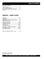
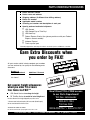
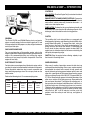
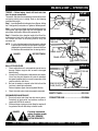
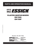
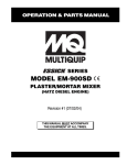
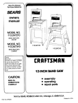
PARTS AND OPERATION MANUAL PLASTER / MORTAR MIXERS © COPYRIGHT 2001, MULTIQUIP INC. EM-900S EM-900P Revision #7 (06/26/01) MULTIQUIP INC.. PARTS DEPARTMENT: 18910 WILMINGTON AVE. 800-427-1244 CARSON, CALIFORNIA 90746 FAX: 800-672-7877 SERVICE DEPARTMENT: 310-537-3700 800-421-1244 800-478-1244 FAX: 310-537-3927 FAX: 310-537-4259 E-mail:[email protected] • www:multiquip.com Atlanta • Boise • Dallas • Houston • Newark Montreal, Canada • Manchester, UK Rio De Janiero, Brazil • Guadalajara, Mexico PAGE 2 — ESSICK EM-900S & 900P — PARTS & OPERATION MANUAL — REV. #7 (06/26/01) HERE'S HOW TO GET HELP PLEASE HAVE THE MODEL AND SERIAL NUMBER ON-HAND WHEN CALLING PARTS DEPARTMENT 800-427-1244 or 310-537-3700 FAX: 800-672-7877 or 310-637-3284 SERVICE DEPARTMENT/TECHNICAL ASSISTANCE 800-478-1244 or 310-537-3700 FAX: 310- 537-4259 WARRANTY DEPARTMENT 888-661-4279, or 310-661-4279 FAX: 310- 537-1173 MAIN 800-421-1244 or 310-537-3700 FAX: 310-537-3927 ESSICK EM-900S & 900P — PARTS & OPERATION MANUAL — REV. #7 (06/26/01) — PAGE 3 TABLE OF CONTENTS Here's How To Get Help .......................................... 3 Table Of Contents ................................................... 4 Parts Ordering Procedures ..................................... 5 Rules for Safe Operation & Safety Decals .............. 6 Warranty .................................................................. 7 ESSICK — 900S & 900P Operations ......................................................... 8-11 Specifications ........................................................ 12 Explanation Of Codes In Remarks Column .......... 14 Suggested Spare Parts ......................................... 15 Drum Head Assembly ...................................... 16-17 Paddle Shaft Assembly .................................... 18-19 Steel Drum (S) ................................................. 20-21 Polyethylene Drum (P) ..................................... 22-23 Gas Engines, Pulleys & Cab Assembly ............ 24-25 Electric Motor & Pulleys ................................... 26-27 Axle & Wheel Group ......................................... 28-29 Terms and Conditions Of Sale — Parts ................ 30 NOTE: Specification and part number are subject to change without notice. PAGE 4 — ESSICK EM-900S & 900P — PARTS & OPERATION MANUAL — REV. #7 (06/26/01) PARTS ORDERING PROCEDURES n n n n n n n Dealer account number Dealer name and address Shipping address (if different than billing address) Return fax number Applicable model number Quantity, part number and description of each part Specify preferred method of shipment: • • • • UPS Ground UPS Second Day or Third Day* UPS Next Day* Federal Express Priority One (please provide us with your Federal Express account number)* • • Airborne Express* Truck or parcel post *Normally shipped the same day the order is received, if prior to 2PM west coast time. Earn Extra Discounts when you order by FAX! All parts orders which include complete part numbers and are received by fax qualify for the following extra discounts: Number of line items ordered 1-9 items Additional Discount 3% 10+ items** 5% Get special freight allowances when you order 10 or more line items via FAX!** n n UPS Ground Service at no charge for freight PS Third Day Service at one-half of actual freight cost No other allowances on freight shipped by any other carrier. **Common nuts, bolts and washers (all items under $1.00 list price) do not count towards the 10+ line items. *DISCOUNTS ARE SUBJECT TO CHANGE* count s i D x Fa A Extra tic US s e m for Do Only s r e l a De Now! Direct TOLL-FREE access to our Parts Department! Toll-free nationwide: 800-421-1244 Toll-free FAX: 800/6-PARTS-7 • 800-672-7877 Fax order discount and UPS special programs revised June 1, 1995 ESSICK EM-900S & 900P — PARTS & OPERATION MANUAL — REV. #7 (06/26/01) — PAGE 5 RULES FOR SAFE OPERATION & SAFETY DECALS ■ Do not operate or service this equipment before reading the operating and maintenance instructions manual or serious injury may result. ■ Do not operate this equipment unless all guards and safety devices are attached and in place. ■ Stop the engine when leaving the equipment. ■ Block the unit when leaving or when using on a slope ■ Maintain this equipment in a safe operating condition at all times. ■ Caution must be exercised while servicing this equipment. Rotating and moving parts can cause injury if contacted. ■ Stop the engine before servicing, adding fuel and oil. ■ When towing, an adequate safety chain must be fastened to the frame, refer to page 9. ■ Keep all inexperienced and unauthorized people away from the equipment at all times. ■ Unauthorized equipment modifications will void all warranties. ■ Check all fasteners periodically for tightness. Also check towing tongue bolt, lock nut and wheel lug nuts for wear. ■ Wear safety glasses at all times when working around machinery. ■ Stop the engine and disconnect the spark plug before allowing anybody’s hands in the mixing drum. ■ Never pour or spray water over the engine or electric motor. ■ Always stand clear of dump handle when mixer is in operation. Any binding of material between the mixer blades and drum will cause drum and handle to quickly move in the discharge position. The safety instruction decals shown must be on all Essick Mixers CAUTION! SHUT OFF ENGINE BEFORE PUTTING HANDS IN MIXING DRUM Caution Decal is: P/N EM948423 SAFETY INSTRUCTIONS 1. Do not operate or service this machine before reading the operating and maintenance manual. 2. Keep all inexperienced and/or unauthorized people away from equipment at all times. 3. Do not operate this equipment unless all guards and safety devices are attached and in place. 4. Keep this equipment in safe operating condition at all times. 5. Caution must be exercised while servicing this equipment. Rotating and moving parts can cause injury if contacted. 6. Stop engine and allow to cool before adding fuel or oil. 7. Stop engine when leaving equipment. 8. Block unit when parking on a slope. 9. Unauthorized equipment modifications will void all warranties. ESSICK CONSTRUCTION PRODUCTS A MULTIQUIP COMPANY CARSON, CALIFORNIA The safety instruction decal is P/N EM948501 PAGE 6 — ESSICK EM-900S & 900P — PARTS & OPERATION MANUAL — REV. #7 (06/26/01) WARRANTY There are no warranties, express or implied, made by Multiquip Inc. hereunder on Products manufactured or distributed by it except the warranty against defects in material and workmanship on new Products to the original purchaser, as hereinafter set forth. Multiquip Inc. warrants Products manufactured by it to be free from defects in material and workmanship under normal and proper use and servicing for the periods specified on the bottom of this page. Warranty on the engines supplied with the Products is limited to the warranty extended by the engine manufacturer. Multiquip Inc.’ sole obligation under this warranty is limited to the replacement or repair, at its Carson, California facility, or such authorized facility, of only such part or parts thereof as shall appear to Multiquip Inc. upon inspection at such facility, to have been defective in material and workmanship. There are no warranties, express or implied, in addition to the above except as may be provided in writing by Multiquip Inc. MULTIQUIP INC. SHALL NOT BE LIABLE FOR ANY SPECIAL, INDIRECT OR CONSEQUENTIAL DAMAGES. THE FOREGOING WARRANTIES ARE IN PLACE AND IN LIEU OF ALL WARRANTIES OF MERCHANTABILITY AND FITNESS AND SETS FORTH THE ENTIRE OBLIGATION OF MULTIQUIP INC. To avoid misrepresentations with respect to Products sold hereunder, the Dealer agrees that no warranties, or other operating guaranties on any Products covered by this Agreement shall be made in excess of those made by Multiquip Inc. Multiquip Inc. Warranty Periods: A statement giving model and serial number of the Product, date of sale to original purchaser and date and description of failure shall accompany all parts. EM-900 .......................... 12 months Any part or parts determined by Multiquip Inc. to be defective will be replaced free of charge, F.O.B. Carson, California. Returned parts subject to warranty must be shipped prepaid to Multiquip Inc. within 30 days from the date the defective part or parts were removed. This warranty does not apply to any part or parts which have been subject to abuse or unauthorized repairs Warranty with respect to Products, components and accessories not manufactured by Multiquip Inc. is limited to the warranty extended by the manufacturer of those items. ESSICK EM-900S & 900P — PARTS & OPERATION MANUAL — REV. #7 (06/26/01) — PAGE 7 EM-900S & 900P — OPERATIONS CONTROLS KILL SWITCH: (Gasoline Engine Only) Located on the side of the engine cover. ENGINE THROTTLE AND CHOKE CONTROLS: Please refer to the engine owners manual for specific instructions. The electric motor switch ( electric motor only) located on the motor — is used to start and stop the mixer. DUMP LATCH: To dump the tub, grasp the dump handle and lift the dump latch, then rotate the tub to discharge the mix. After, discharge, return the tub to the vertical mixing position. CLUTCH GENERAL The Essick EM-700 and EM-900 Series plaster and mortar mixers are quality mixers that have a batch capacity of 2.5 and 3.5 bags respectively. With proper care, they will give continuous service year-after-year. GASOLINE ENGINE CARE For care and operation of the gasoline engine, refer to the engine manufacturer’s operating instructions furnished with the engine. We recommend draining and refilling the engine crankcase at least every thirty hours of operation. Check the engine oil level daily. The paddle shaft and mixing blades are engaged and disengaged by tightening and loosening the drive belts with a spring loaded idler pulley. To engage the clutch, rotate the lever locates at the front of the mixer counterclockwise. The spring maintains the correct belt tension. To disengage the clutch, rotate the lever clockwise against the lever stop. The engine base is slotted to adjust for belt wear and to bring the idler pulley into operating range. CAUTION: Stop the engine before allowing anybody to put their hands in the mixing drum. ELECTRIC MOTOR CARE WHEEL BEARINGS For lubrication care and operation of the electric motor, refer to your electric motor instruction booklet furnished with the motor. After every 3 months of operation, remove the hub dust cap and inspect the wheel bearings. Once a year, or when required, disassemble the wheel hubs remove the old grease and repack the bearings forcing grease between rollers, cone and cage with a good grade of high speed wheel bearing grease (never use grease heavier than 265 A.S.T.M. penetration “No. 2.”) Fill the wheel hub with grease to the inside diameter of the outer races and also fill the hub grease cap. Reassemble the hub and mount the wheel. Then tighten the adjusting nut, at the same time turn the wheel in both directions, until there is a slight bind to be sure all the bearing surfaces are in contact. Then back-off the adjusting nut 1/6 to 1/4 turn or to the nearest locking hole or sufficiently to allow the wheel to rotate freely within limits of .001" to .010" end play. Lock the nut at this position. Install the cotter pin and dust cap, and tighten all hardware. Protect the electric motor from dust as much as possible and keep ventilating openings clean. Do not spray water on the electric motor. Refer to the following chart. For recommend plug sizes. MOTOR 115 VOLT 1Ø EM 700 230 VOLT 1Ø EM 900 HORSE POWER PIGTAIL CAP CONN BODY NEMA/ NEMA/ ESSICK ESSICK PIGTAIL CAP CONN BODY NEMA/ NEMA/ ESSICK ESSICK 1½ & 3 HP L5-30P/940545 L5-30R/940546 L6-15P/940550 L6-15R/940551 PAGE 8 — ESSICK EM-900S & 900P — PARTS & OPERATION MANUAL — REV. #7 (06/26/01) EM-900S & 900P — OPERATIONS PADDLE SHAFT BEARING IMPORTANT — DRUM HEAD SEAL CARE The paddle shaft in the Essick Mixer rotates in sealed ball bearings requiring no additional lubrication. On each end of the mixing drum is a drum head containing self adjusting paddle shaft seals. These seals consist of packing rings, split glands and spring actuated adjusters. A properly maintained seal prevents material from working around the paddle shaft, causing excessive wear. The following is a suggested procedure of maintenance for protection of the paddle shaft and bearings: BEARING BRACKET Grease the bearing bracket every month. COUNTERSHAFT The countershaft rotates on two self-aligned pillow block bearings. Grease these every 40 hours using grade #1 Lithium Base grease. GEAR ALIGNMENT The countershaft and driven pinion are mounted on a slotted base. To align gears, loosen pillow block mounting bolts and move them until the necessary alignment has been made. GEAR LUBRICATION The surface of the pinion and the bull gear should be very lightly greased every 250 hours. IMPORTANT! AVOID OVER-GREASING. EXCESS GREASE WILL ACCUMULATE CONTAMINATES AND CAUSE PREMATURE WEAR. A. Keep the drum head clean of plaster built up, so the spring adjusters will be free to work. B. Replace with one new ring of packing and waterproof grease when split gland or pressure plate is about to bottom out against the end of the drum. New Packing When the old packing is to be completely replaced, coat shaft and packing generously with a good grade of waterproof grease and insert packing rings. Tighten the two spring adjuster nuts on each end until the spring is compressed to 1¾ inches or the top of the adjusting nut is even with the top of the drum head. Also, whenever the paddle shaft is removed, new waterproof grease should be packed around the ball bearings in the drum heads before reinstalling the shaft. Fill the cavity completely. DRUM GRILL The drum opening is covered by a steel grill that is hinged for easy cleaning. This grill should be closed at all times when mixer is in use. Do not remove the grill or grill opening bar. Keep the grill clean by washing it down daily. CAUTION: Stop the engine before allowing anybody to put their hands in the mixing drum. ESSICK EM-900S & 900P — PARTS & OPERATION MANUAL — REV. #7 (06/26/01) — PAGE 9 EM-900S & 900P — OPERATIONS TOWING — Before towing, check with local and state laws for proper compliance. The tow bar and chain must be properly attached to the mixer and towing vehicle prior to towing. Refer to the following installation instruction: Step 1. Insert the Draw Bar into the main frame. Secure, utilizing the ¾" bolt (grade 5) and nylock nut. Tighten to 100 foot pounds. Step 2. Install the chain through the hole located between the frame gusset and frame angle. Loop the chain together and place under the Draw Bar. Secure with connector link. Step 3. Extend the chain along the length of the Draw Bar, remove excess chain (slack) and secure to bottom connector link. Secure the chain to the towing vehicle, using the connector link. NOTE: It is critical that the length of chain be properly adjusted to prevent the Draw Bar and front mixer stand from dropping to the ground (contact) in the event the Draw Bar becomes disconnected from the towing vehicle. DANGER BEFORE TOWING STEP 1 DRAW BAR BOLT & NUT INSERT CHAIN THROUGH THE HOLE STEP 2 DRAW BAR FRAME ANGLE FRAME GUSSET CONNECTOR LINK BALL HITCH COUPLER 1. Check vehicle hitch, ball, and coupler for signs of wear or damage. Replace any parts that are worn or damaged before towing. 2. Use only the 2" ball diameter as indicated on your coupler. Use of any other ball diameter will create an extremely dangerous condition which can result in separation of the coupler and ball or ball failure. 3. Be sure the coupler is secured to the hitch ball and the lock lever is down tight and locked. Recheck tightness again after towing about 50 miles. 4. Check that trailer safety chains are properly connected. STEP 3 VEHICLE CONNECTOR LINK DRAW BAR REMOVE EXCESS CHAIN (SLACK) BOTTOM CONNECTOR LINK SAFETY CHAIN .........................................P/N 3148 RECOMMENDED MAINTENANCE 1. Smear ball socket and clamp face with chassis grease. Periodically oil pivot points and solutions surfaces of coupler with SAE 30 wt. motor oil. 2. When parking or storing your trailer. Keep the coupler off the ground so dirt will not build up in the ball socket. DANGER CONNECTOR LINK ...................................P/N 01004 If housing is deformed, replace complete coupler. USE ONLY GENUINE FULTON REPAIR KITS. PAGE 10 — ESSICK EM-900S & 900P — PARTS & OPERATION MANUAL — REV. #7 (06/26/01) EM-900S & 900P — OPERATIONS CLEANING — BLADE ADJUSTMENTS END SCRAPER Always disconnect the spark plug wire before cleaning the inside of the drum. Never pour or spray water over the gasoline engine or electric motor. For consistent performance, long life and high quality mixing, thoroughly clean the mixer inside and out at the end of each day’s operation. To prevent lumps of dried mortar from forming and contamination of future batches, do not allow a buildup of materials to form on the blades or anywhere inside the drum. The following is the recommended wiper blade adjustments: 1) STEEL DRUM MIXERS SIDE SCRAPER 2) POLYETHYLENE DRUM MIXERS The poly blade should come as close as possible to the surface without touching. If material builds up on the drum, you may use a rubber mallet to dislodge the material without adverse effect to the drum. IMPORTANT NOTICE EPOXY COMPATIBILITY — There are some expoxies and other chemicals used in certain applications that are not compatible with polyethylene tubs. Since Whiteman Industries cannot control the end user’s application of this product, we will not assume responsibility for the resulting damages when exposed to incompatible chemicals. ESSICK EM-900S & 900P — PARTS & OPERATION MANUAL — REV. #7 (06/26/01) — PAGE 11 EM-900S & 900P — SPECIFICATIONS EM-900S SPECIFICATIONS MODEL U.S.(inch) METRIC CAPACITY .................................................... 9 CUBIC FEET ....................................................... 248 LITERS BAG CAPACITY ............................................. 2½ - 3½ ............................................................ 2½ - 3½ WEIGHT (APPROX.) ....................................... 780 LBS. ............................................................. 395 KG. L X W X H .................................................. 71 X 50 X 59 IN. .................................................. 180 X 127 X 150 CM. LENGTH W/TOW BAR ...................................... 98 IN. ................................................................. 248 CM. HEIGHT W/DUMP HANDLE ................................ 77 IN. ................................................................. 195 CM. DISCHARGE HEIGHT ....................................... 21 IN. ................................................................. 53 CM. DRIVE ......................................................... V-BELT TO GEAR ..................................................... — DUMP ACTION .............................................. MANUAL ............................................................... — EM-900P SPECIFICATIONS MODEL U.S.(inch) METRIC CAPACITY .................................................... 9 CUBIC FEET ....................................................... 248 LITERS BAG CAPACITY ............................................. 2½ - 3½ ............................................................ 2½ - 3½ WEIGHT (APPROX.) ....................................... 796 LBS. ............................................................. 395 KG. L X W X H .................................................. 71 X 50 X 59IN. ................................................... 180 X 127 X 150 CM. LENGTH W/TOW BAR ...................................... 98 IN. ................................................................. 248 CM. HEIGHT W/DUMP HANDLE ................................ 77 IN. ................................................................. 195 CM. DISCHARGE HEIGHT ....................................... 21 IN. ................................................................. 53 CM. DRIVE ......................................................... V-BELT TO GEAR ..................................................... — DUMP ACTION .............................................. MANUAL ............................................................... — NOTE: In accordance with our established policy of constant improvement, we reserve the right to amend these specifications at anytime without notice. PAGE 12 — ESSICK EM-900S & 900P — PARTS & OPERATION MANUAL — REV. #7 (06/26/01) NOTE PAGE ESSICK EM-900S & 900P — PARTS & OPERATION MANUAL — REV. #7 (06/26/01) — PAGE 13 EXPLANATION OF CODE IN REMARKS COLUMN How to read the marks and remarks used in this parts book. Section 1: Items Found In the “Remarks” Column Serial Numbers-Where indicated, this indicates a serial number range (inclusive) where a particular part is used. Model Number-Where indicated, this shows that the corresponding part is utilized only with this specific model number or model number variant. Section 2: Items Found In the “Remarks” Column Serial Numbers-Where indicated, this indicates a serial number range (inclusive) where a particular part is used. Model Number-Where indicated, this shows that the corresponding part is utilized only with this specific model number or model number variant. Section 3: Items Found In the “Items Number” Column All parts with same symbol in the number column, , #, +, %, or ■, belong to the same assembly or kit. * Note: If more than one of the same reference number is listed, the last one listed indicates newest (or latest) part available. NOTE If more than one of the same reference number is listed, the last one listed indicates newest (or latest) part available. NOTE The contents of this catalog are subject to change without notice. PAGE 14 — ESSICK EM-900S & 900P — PARTS & OPERATION MANUAL — REV. #7 (06/26/01) EM-900S & 900P — SUGGESTED SPARE PARTS EM-900 S/P EM-900 S/P 1 to 3 Units 5+ Units Qty. P/N Description 3 ......... EM505834 ........... V-BELT 3 ......... 491115 ................ V-BELT, w/ELECTRIC MOTOR 6 ......... 491010 ................ LATCH w/ASSY 3 ......... EM200863 ........... BLADE KIT STEEL DRUM 3 ......... EM204625 ........... BLADE KIT POLY DRUM 12 ....... EM200301 ........... PACKING RING 4 ......... EM200794 ........... SPRING 4 ......... EM200286 ........... SPECIAL BOLT 1 ......... 3351 .................... PINION GEAR Qty. P/N Description 5 ......... EM505834 ........... V-BELT 5 ......... 491115 ................ V-BELT, w/ELECTRIC MOTOR 10 ....... 491010 ................ LATCH w/ASSY 5 ......... EM200863 ........... BLADE KIT STEEL DRUM 5 ......... EM204625 ........... BLADE KIT POLY DRUM 24 ....... EM200301 ........... PACKING RING 8 ......... EM200794 ........... SPRING 8 ......... EM200286 ........... SPECIAL BOLT 2 ......... EM902153 ........... BEARING 1 ......... EM940734 ........... SWITCH, ON/OFF 1 ......... 509171 ................ DUMP HANDLE: POLY DRUM 2 ......... 3351 .................... DRIVEN PINON GEAR 1 ......... EM201537 ........... DUMP HANDLE, STEEL DRUM 2 ......... 3065 .................... SEAL, AXLE 2 ......... 3469 .................... DUST CAP AXLE 2 ......... EM903049 ........... BEARING CONE UP TO S/N 9896000 2 ......... EM903113 ........... BEARING CONE STARTING S/N 2080000 2 ......... EM903012 ........... BEARING CUP NOTE Part numbers on this Suggested Spare Parts List may supercede/ replace the P/N shown in the text pages of this book. ESSICK EM-900S & 900P — PARTS & OPERATION MANUAL — REV. #7 (06/26/01) — PAGE 15 EM-900S & 900P — DRUM HEAD ASSEMBLY PAGE 16 — ESSICK EM-900S & 900P — PARTS & OPERATION MANUAL — REV. #7 (06/26/01) EM-900S & 900P — DRUM HEAD ASSEMBLY DRUM HEAD ASSEMBLY DRUM HEAD NO. PART NO. PART NAME 4 5 6 6 7 8 9 10 11 12 13 13 14 15 16 EM200018 EM902153 EM507720 500076 EM916019 EM200288 EM200286 EM200285 EM200303 EM200301 EM201648 EM507272 EM200794 EM200287 EM966048 COLLAR 1 BEARING 2 DUMP BEARING ..................................................................... 2 ................. STARTING S/N 98624090 DUMP BEARING ..................................................................... 2 ................. FROM S/N 9862400 TO 9862489 GREASE ZERK ........................................................................ 2 ................. REPLACES 491705 ADJUSTING PLATE 2 SPECIAL BOLT 4 PACKING GLAND HALF 4 FOLLOWER 2 PACKING RING 12 DRUM HEAD ........................................................................... 2 ................. STARTING S/N 98624090 DRUM HEAD ........................................................................... 2 ................. FROM S/N 9862400 TO 9862489 SPRING 4 ADJUSTING NUT 4 BOLT 8 QTY. REMARKS ESSICK EM-900S & 900P — PARTS & OPERATION MANUAL — REV. #7 (06/26/01) — PAGE 17 EM-900S, 900P — PADDLE SHAFT ASSEMBLY 46 47 48 49 61 58 59 60 TOW END PAGE 18 — ESSICK EM-900S & 900P — PARTS & OPERATION MANUAL — REV. #7 (06/26/01) EM-900S, 900P — PADDLE SHAFT ASSEMBLY PADDLE SHAFT ASSEMBLY NO. PART NO. PART NAME 46 47 48 49 50 51 52 53 54 # 55 # 56 56# 57 57# 58 59 60 61 EM200297 EM968011 EM200292 EM507274 EM200293 EM200294 EM200296 EM200295 EM203432 EM203433 EM200212 EM507519 EM200213 EM507518 EM963837 6109180 EM968011 EM507251 EM200863 EM204625 EM203028 U-BOLT 2 NUT HEX ½-13 4 U-BOLT INSERT 4 PADDLE SHAFT PADDLE ARM-TOW END 1 PADDLE ARM-CENTER 1 PADDLE ARM-ENGINE END 1 PADDLE ARM-CENTER 1 CENTER BACK-UP BLADE 4 END BACK-UP BLADE 2 TOP RUBBER BLADE (STEEL) DRUM ONLY 4 TOP PLASTIC BLADE (POLY) DRUM ONLY 4 END RUBBER BLADE (STEEL) DRUM ONLY 2 END PLASTIC BLADE (POLY) DRUM ONLY 2 BOLT ½"-13 X 5-½" 1 LOCK WASHER ½" 1 REPLACES EM923638 HEX NUT ½"-13 1 SPACER, BULL GEAR 1 BLADE KIT, (STEEL) DRUM ONLY .......................................... 1 ............... INCLS ITEMS w/ AND MTG. HDWR BLADE KIT, (POLY) DRUM ONLY ............................................. 1 ............... INCLS ITEMS w/# AND MTG. HDWR HARDWARE KIT, (RUBBER/POLY BLADES) ........................... 1 ............... INCLUDED IN BLADE KITS * * * * QTY. REMARKS * REFER TO PAGES 14 & 15 FOR DRUM HEAD BREAKDOWN ESSICK EM-900S & 900P — PARTS & OPERATION MANUAL — REV. #7 (06/26/01) — PAGE 19 EM-900S — STEEL DRUM STEEL DRUM 109 110 111 108 PAGE 20 — ESSICK EM-900S & 900P — PARTS & OPERATION MANUAL — REV. #7 (06/26/01) EM-900S — STEEL DRUM STEEL DRUM NO. PART NO. 100# 101 101 101 102 103 104# 105# 106% EM201537 EPC-1 EBC-1 HBC-1 EM963580 EM969038 EM203332 EM507484 EM507765 EM507766 108 109 110 111 ❑ ❑ ❑ PART NAME QTY. REMARKS DUMP HANDLE 1 TOWING TONGUE (P. EYE) .................................... 1 .............. NO LONGER AVAILABLE TOWING TONGUE (PIN HOLE) .............................. 1 .............. CONTACT MQ SALES DEPT./ACCESSORY ITEM TOWING TONGUE (BALL HITCH) .......................... 1 .............. CONTACT MQ SALES DEPT./ACCESSORY ITEM CAP SCREW ........................................................... 1 .............. REPLACES 505067 LOCK NUT ............................................................... 1 .............. REPLACES 505069 DRUM GRILL 1 GRILL OPEN BAR 1 DRUM ASSY (STEEL) ............................................. 1 .............. INCLS. ITEMS w/# DRUM & SHAFT ASSY (COMPLETE) (STEEL) ..... 1 .............. INCLS. ITEMS w/% AND DRUM HEAD & PADDLE SHAFT ASSY EM506309 MAIN FRAME 1 507264 CLUTCH LEVER 1 EM507421 DUMP LATCH 1 EM507835 CLEVIS PIN 1 3148 SAFETY CHAIN 1 REPLACES 13363 01004 5/16" CONNECTOR LINK 2 ILLUSTRATED ON PAGE 10 ESSICK EM-900S & 900P — PARTS & OPERATION MANUAL — REV. #7 (06/26/01) — PAGE 21 EM-900P — POLYETHYLENE DRUM POLYETHYLENE DRUM 122 123 124 125 126 127 124 125 128 129 PAGE 22 — ESSICK EM-900S & 900P — PARTS & OPERATION MANUAL — REV. #7 (06/26/01) EM-900P — POLYETHYLENE DRUM POLYETHYLENE DRUM NO. PART NO. PART NAME 115# 116 117# 118# 119# 120# 121 EM506310 EM506897 507416 507417 507517 509171 EM506896 EM509604 122 123 124 125 126 127 128 129 EM963610 EM969013 5041987 EM969079 505196 505066 492392 492584 PLASTIC DRUM W/O GRATES 1 SUPPORT REAR 1 STATIONARY GRATE 1 MOVEABLE GRATE 1 GRATE OPEN BAR 1 DUMP HANDLE 1 DRUM SUPPORT 1 DRUM & SHAFT ASSY (COMPLETE) (POLY) ........................ 1 ...................... INCLS ITEMS W/# AND HEAD END & PADDLE SHAFT ASSY HHCS 3/8" NC X 1/4" G-5 ....................................................... 7 ...................... REPLACES 492376 LOCK NUT 3/8" NC ................................................................. 7 ...................... REPLACES 492583 FHCS 1/4" NC X 1" G-5 ........................................................... 8 ...................... REPLACES 504987 LOCK NUT 1/4" NC ................................................................. 8 ...................... REPLACES 492581 3/8 X 1½" HHCS 8 3/8" LOCKNUT 8 ½" X 1 NC G-5 BOLT 3 ½" LOCK NUT 3 QTY. REMARKS ESSICK EM-900S & 900P — PARTS & OPERATION MANUAL — REV. #7 (06/26/01) — PAGE 23 EM-900S & 900P — GAS ENGINES, PULLEYS & CAB ASSEMBLY CAB ASSEMBLY PAGE 24 — ESSICK EM-900S & 900P — PARTS & OPERATION MANUAL — REV. #7 (06/26/01) EM-900S & 900P — GAS ENGINES, PULLEYS & CAB ASSEMBLY GAS ENGINES, PULLEYS & CAB ASSEMBLY COMMON PARTS NO. PART NO. PART NAME 150 151 152 153 154 155 156 157 158 159 167 168 169 170 171 EM507159 491010 EM505671 EM959080 EM102014 EM901515 EM905016 EM203098 3351 EM940734 502226 JISB2804C25 500214 EM010023 EM963064 CAB ASSEMBLY 1 LATCH ASSEMBLY ................................................. 2 .................. REPLACES 504744 DRIVE GEAR 16-½ DIA. 1 ROD END 2 SPRING 1 IDLER PULLEY 1 PILLOW BLOCK BEARING 2 SPRING CLIP 1 DRIVEN PINION GEAR .......................................... 1 .................. REPLACES 500272 SWITCH, ON/OFF 1 COUNTER SHAFT 1 SNAP RINGS .......................................................... 2 .................. REPLACES 490957 KEY 1 KEY 1 BOLT 3/8 X16 X 3-1/4 1 QTY. REMARKS MODEL EM 900 w/HONDA NO. PART NO. PART NAME 161 161 162 163 163 164 165 166 GX240K1HA2 GX160K1HX2 492057 EM901074 492055 EM505834 EM507490 EM507491 HONDA ENGINE GX240 K1HA 8HP ...................... 1 .................. REPLACES 493261 HONDA ENGINE GX160 5.5HP ENG. 1 DRIVEN PULLEY-LARGE 1 DRIVE PULLEY-SMALL 1" BORE-8HP HONDA 1 DRIVE PULLEY-5.5 HP HONDA 1 V-BELT 2 THREADED ROD 1 IDLER ARM 1 QTY. REMARKS MODEL EM900 w/WISCONSIN NO. PART NO. PART NAME 161 162 163 164 165 166 EM937171 EM505204 505205 507775 EM507771 EM203352 WISCONSIN ENGINE BKN2-408472 ..................... 1 .................. REPLACES 505208 DRIVEN PULLEY 1 DRIVE PULLEY 1 V-BELT 2 THREADED ROD 1 IDLER ARM 1 QTY. REMARKS MODEL EM 900 w/ROBIN NO. PART NO. PART NAME 161 161 162 163 164 165 166 W1280800466 EH252YR0000 492057 492054 EM505834 EM507490 EM203352 ROBIN ENGINE 8HP EY-28 .................................... 1 .................. UP TO OCTOBER, 1999 ROBIN ENGINE 8HP EH25-2 ................................. 1 .................. STARTING OCTOBER, 1999, REPLACES 493260 DRIVEN PULLEY-LARGE 1 DRIVE PULLEY-SMALL 1 V-BELT 2 THREADED ROD 1 IDLER ARM 1 QTY. REMARKS MODEL EM-900 w/B&S NO. PART NO. PART NAME 161 161 162 163 164 165 166 1964521049 1352321036E1 492057 EM901074 EM505834 EM507490 EM507491 B&S ENGINE 8HP .................................................. 1 .................. REPLACES 493181 B&S ENGINE 5HP 1 DRIVEN PULLEY-LARGE 1 DRIVE PULLEY-SMALL 1" BORE 1 V-BELT 2 THREADED ROD 1 IDLER ARM 1 QTY. REMARKS ESSICK EM-900S & 900P — PARTS & OPERATION MANUAL — REV. #7 (06/26/01) — PAGE 25 EM-900S & 900P — ELECTRIC MOTOR & PULLEYS CAB ASSEMBLY PAGE 26 — ESSICK EM-900S & 900P — PARTS & OPERATION MANUAL — REV. #7 (06/26/01) EM-900S & 900P — ELECTRIC MOTOR & PULLEYS ELECTRIC MOTOR & PULLEYS NO. PART NO. PART NAME 161 162 163 164 165 166 EM939315 EM505204 EM901513 491115 EM507490 EM507713 507715 ELECTRIC MOTOR 3.0 H.P 1 DRIVEN PULLEY 1 DRIVE PULLEY 1 V-BELT 2 THREADED ROD 1 IDLER ARM 1 GUIDE, V-BELT .................................................................................. 1 ................. NOT ILLUSTRATED QTY. REMARKS FOR COMMON PARTS SEE PAGE 25 ESSICK EM-900S & 900P — PARTS & OPERATION MANUAL — REV. #7 (06/26/01) — PAGE 27 EM-900S & 900P — AXLE & WHEEL GROUP PAGE 28 — ESSICK EM-900S & 900P — PARTS & OPERATION MANUAL — REV. #7 (06/26/01) EM-900S & 900P — AXLE & WHEEL GROUP WHEEL GROUP EM-700 & 900 NO. PART NO. PART NAME 200 200 201 # 202 203 204 204 205 206 208 209 # 210 # 211 211# 212 # 213 213 EM507407 511334 3065 504708 507444 3068 8164 0183 3005 EM942000 3469 8115 EM903049 EM903113 EM903012 3504 EM941306 AXLE, RIGID ....................................... 1 .................... UP TO S/N 98960000 AXLE, RIGID ....................................... 1 .................... STARTING S/N 20800000 SEAL 2 THICK SPACER .................................. 2 .................... 3/4" INSIDE DIAMETER THIN SPACER .................................... 2 .................... 3/4" INSIDE DIAMETER AXLE NUT ........................................... 2 .................... UP TO S/N 98960000 AXLE NUT ........................................... 2 .................... STARTING S/N 20800000 COTTER PIN 2 RIM & TIRE ONLY 2 VALVE STEM ....................................... 1 .................... REPLACES 942052 DUST CAP 2 LUG NUT 8 BEARING CONE ................................. 2 .................... UP TO S/N 98960000 BEARIING CONE ................................ 2 .................... STARTING S/N 20800000 BEARING CUP 2 HUB W/ BEARING CUP ...................... 2 .................... UP TO S/N 9896000, INCLUDES ITEM w/ HUB W/ BEARING CUP ...................... 2 .................... STARTING S/N 20800000, INCLUDES ITEM w/# * * * * * QTY. REMARKS ESSICK EM-900S & 900P — PARTS & OPERATION MANUAL — REV. #7 (06/26/01) — PAGE 29 * TERMS AND CONDITIONS OF SALE — PARTS Effective: July 1, 2000 PAYMENT TERMS 4. Terms of payment for parts are net 10 days. FREIGHT POLICY All parts orders will be shipped collect or prepaid with the charges added to the invoice. All shipments are F.O.B. point of origin. Multiquip’s responsibility ceases when a signed manifest has been obtained from the carrier, and any claim for shortage or damage must be settled between the consignee and the carrier. Freight is at the sender’s expense. All parts must be returned freight prepaid to Multiquip’s designated receiving point. 5. Parts must be in new and resalable condition, in the original Multiquip package (if any), and with Muiltiquip part numbers clearly marked. 6. The following items are not returnable: a. Obsolete parts. (If an item is listed in the parts price book as being replaced by another item, it is obsolete.) b. Any parts with a limited shelf life (such as gaskets, seals, “O” rings, and other rubber parts) that were purchased more than six months prior to the return date. MINIMUM ORDER The minimum charge for orders from Multiquip is $15.00 net. Customers will be asked for instructions regarding handling of orders not meeting this requirement. c. Any line item with an extended dealer net price of less than $5.00. PRICING AND REBATES Prices are subject to change without prior notice. Price changes are effective on a specific date and all orders received on or after that date will be billed at the revised price. Rebates for price declines and added charges for price increases will not be made for stock on hand at the time of any price change. Multiquip reserves the right to quote and sell direct to Government agencies, and to Original Equipment Manufacturer accounts who use our products as integral parts of their own products. SPECIAL EXPEDITING SERVICE A $20.00 to $50.00 surcharge will be added to the invoice for special handling including bus shipments, insured parcel post or in cases where Multiquip must personally deliver the parts to the carrier. d. Special order items. RETURNED GOODS POLICY e. Electrical components. Return shipments will be accepted and credit will be allowed, subject to the following provisions: f. Paint, chemicals, and lubricants. LIMITATIONS OF SELLER’S LIABILITY g. Decals and paper products. 1. h. Items purchased in kits. Multiquip shall not be liable here under for damages in excess of the purchase price of the item with respect to which damages are claimed, and in no event shall Multiquip be liable for loss of profit or good will or for any other special, consequential or incidental damages. 2. A Returned Material Authorization must be approved by Multiquip prior to shipment. To obtain a Return Material Authorization, a list must be provided to Multiquip Parts Sales that defines item numbers, quantities, and descriptions of the items to be returned. a. b. The list must be typed or computer generated. c. The list must state the reason(s) for the return. d. The list must reference the sales order(s) or invoice(s) under which the items were originally purchased. e. 3. The parts numbers and descriptions must match the current parts price list. The list must include the name and phone number of the person requesting the RMA. A copy of the Return Material Authorization must accompany the return shipment. 7. The sender will be notified of any material received that is not acceptable. 8. Such material will be held for 5 working days from notification, pending instructions. If a reply is not received within 5 days, the material will be returned to the sender at his expense. 9. Credit on returned parts will be issued at dealer net price at time of the original purchase, less a 15% restocking charge. 10. In cases where an item is accepted for which the original purchase document can not be determined, the price will be based on the list price that was effective twelve months prior to the RMA date. 11. Credit issued will be applied to future purchases only. LIMITATION OF WARRANTIES No warranties, express or implied, are made in connection with the sale of parts or trade accessories nor as to any engine not manufactured by Multiquip. Such warranties made in connection with the sale of new, complete units are made exclusively by a statement of warranty packaged with such units, and Multiquip neither assumes not authorizes any person to assume for it any other obligation or liability whatever in connection with the sale of its products. A part from such written statement of warranty, there are no warranties, express, implied or statutory, which extend beyond the description of the products on the face hereof. PAGE 30 — ESSICK EM-900S & 900P — PARTS & OPERATION MANUAL — REV. #7 (06/26/01) NOTE PAGE ESSICK EM-900S & 900P — PARTS & OPERATION MANUAL — REV. #7 (06/26/01) — PAGE 31 PARTS AND OPERATION MANUAL HERE'S HOW TO GET HELP PLEASE HAVE THE MODEL AND SERIAL NUMBER ON-HAND WHEN CALLING PARTS DEPARTMENT 800-427-1244 or 310-537-3700 FAX: 800-672-7877 or 310-637-3284 ^^^^^*^^^^^^^^^^^^^^^^^^^^^^^^^*^6668 SERVICE DEPARTMENT/TECHNICAL ASSISTANCE 800-478-1244 or 310-537-3700 FAX: 310- 537-4259 WARRANTY DEPARTMENT 888-661-4279, or 310-661-4279 FAX: 310- 537-1173 MAIN 800-421-1244 or 310-537-3700 FAX: 310-537-3927 MULTIQUIP INC. POST OFFICE BOX 6254 CARSON, CA 90749 310-537-3700 • 800-421-1244 FAX: 310-537-3927 E-MAIL: [email protected] WWW: multiquip.com Atlanta • Boise • Dallas • Houston • Newark Quebec, Canada • Manchester, UK • Rio De Janiero, BR • Guadalajara, MX