1
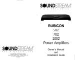
CHAMP series
2- and 4-channel power amplif iers
12
8
6
SIGNAL
LIMIT
ON
4
PROTECT 24
8
2
-dB
•
12
8
6
0
SIGNAL
LIMIT BRIDGE MODE
2
-dB
CH 1+2
0
CHANNEL 2
2.350
ON
10
12
8
14
6
18
4
PROTECT 24
CHANNEL 1
2.250
10
14
18
• 2.500
SIGNAL
4
PROTECT 24
2
-dB
0
CHANNEL 3
•
LIMIT
ON
10
8
14
6
18
SIGNAL
LIMIT BRIDGE MODE
4
PROTECT 24
CH 3 + 4
2
8
10
14
18
8
ON
8
12
POWER ON
-dB
0
AMP 250
CHANNEL 4
4.120
4 x 250 W POWER AMPLIFIER X-OVER
•
4.250X
Bedienungsanleitung
Owner‘s manual
K000001A01.indd
1
12.12.2000, 14:16
Sicherheitshinweise
-
Achtung
Gefahr durch elektrischen Schlag.
Gerät nicht öffnen.
K000001A01
Q
Um Gefährdung durch elektrischen Schlag zu vermeiden, darf das Gehäuse nicht geöffnet werden.
Es befinden sich keine vom Benutzer reparierbaren Teile im Inneren des Gerätes.
Überlassen Sie jegliche Reparatur einem qualifizierten Fachmann.
1. Bitte Bedienungsanleitung genau studieren - Alle Sicherheits- und Bedienungsanweisungen müssen vor
Inbetriebnahme des Gerätes gelesen werden.
2. Bedienungsanleitung für zukünftige Referenz aufbewahren!
3. Warnhinweise beachten - Alle Warnhinweise auf dem Gerät und in dieser Anleitung müssen genau
beachtet werden.
4. Wasser und Feuchtigkeit - Dieses Gerät darf nicht in der Nähe von Wasser (z.B. Badewanne, Waschbecken,
Spülbecken, Waschbottich, feuchte Keller, Swimming Pool usw.) benutzt werden.
5. Hitze - Dieses Gerät sollte nicht in der Nähe von Hitzequellen, z.B. Heizkörpern, betrieben werden.
6. Schutz des Netzkabels - Das Netzkabel muß so verlegt werden, dass ein Quetschen durch Drauftreten
oder durch Gegenstände vermieden wird. Das Netzkabel ist besonders am Netzstecker und an der Stelle
des Geräteeintritts vor mechanischer Überbelastung zu schützen.
7. Nichtbenutzung - Bei längerer Nichtbenutzung des Gerätes sollte das Netzkabel aus der Steckdose
gezogen werden.
8. Fremdkörper und Flüssigkeiten - Das Eindringen von Gegenständen und Flüssigkeiten in das Gehäuse
ist zu vermeiden.
9. Schäden mit Reparaturbedarf - Das Gerät sollte in folgenden Fällen qualifiziertem Fachpersonal zum
Service übergeben werden:
· Gegenstände oder Flüssigkeiten sind in das Gerät eingedrungen, oder
· Das Gerät wurde Regen ausgesetzt, oder
· Das Gerät arbeitet offensichtlich nicht normal oder mit veränderten Eigenschaften, oder
· Das Gerät wurde fallengelassen oder das Gehäuse beschädigt.
10. Reparaturen - Der Benutzer darf keine über die in dieser Anleitung heraus beschriebenen Wartungs- oder
Servicearbeiten durchführen. Alle weitergehenden Servicearbeiten sind qualifiziertem Fachpersonal zu
überlassen.
11. Zum Schutz vor elektrischem Schlag dürfen nur solche Netz-Steckdosen benutzt werden, bei denen ein
Freistehen der Kontakte ausgeschlossen ist.
12. Erdung oder Verpolung - Es sind Vorsichtsmaßnahmen zu treffen, die ein Ausfallen der Schutzerdung
oder Verpolung verhindern.
13. Interner Spannungswahlschalter - Der interne Spannungswahlschalter sollte nur von qualifiziertem Fachpersonal und zusammen mit einer Angleichung des Steckersystems verändert werden.
WARNUNG: Um die Gefahr eines Brandes bzw. eine Verletzung durch elektrischen Schlag zu vermeiden,
sollte das Gerät niemals Regen oder Feuchtigkeit ausgesetzt werden.
2
K000001A01.indd
CHAMP Series owner‘s manual © Zeck Audio 2000
2-3
12.12.2000, 14:16
K000001A01
Safety instructions
-
Caution
Risk of electric shock.
Do not open.
Q
TO REDUCE THE RISK OF ELECTRIC SHOCK DO NOT REMOVE COVERS
NO USER SERVICEABLE PARTS INSIDE.
REFER SERVICING TO QUALIFIED PERSONNEL.
1. Read Instructions - All safety and operation instructions should be read before this Zeck unit is operated.
2. Keep Instructions - The operating instructions may serve as a future reference.
3. Observe Warnings - All warnings on the unit and in this operating instructions should be strictly followed.
4. Water and Moisture - This unit should not be used near water - for example, near a bathtub, washbowl,
kitchen sink, laundry tub, in a wet basement or near a swimming pool, etc.
5. Heat - This unit should be placed away from heat sources, such as radiators or other devices which
produce heat.
6. Power cord protection - power supply cords should be routed so that they are not likely to be stepped
on or pinched by objects placed on or against them, paying particular attention to cords near plugs,
convenience outlets, and the point where they exit the unit.
7. Non-use periods - The power cord of the unit should be unplugged from the outlet when not used for
a longer period.
8. Object and liquid entry - Care should be taken so that objects do not fall into and liquids are not spilled
into the inside of the unit.
9. Damage requiring service - The unit should be serviced only by qualified service personnel when: ·
· objects have fallen, or liquid has spilled into the unit; or
· the unit has been exposed to rain; or
· the unit does not appear to operate normally or exhibits a marked change in performance; or
· the unit has been dropped, or its chassis damaged.
10. Servicing - The user should not attempt to service the unit beyond those means described in this
operating manual. All other servicing should be referred to qualified service personnel.
11. To prevent electric shock, do not use this polarized plug with an extension cord, receptacle or other outlet
unless the prongs can be fully inserted to prevent contact exposure.
12. Grounding or polarization - Precautions should be taken so that the grounding or polarization means
of the unit is not defeated.
13. Internal voltage selectors - Internal line voltage selector switches should only be reset and re-equipped
with a proper plug for alternate voltage by a qualified service technician. For more information, contact
an authorized Zeck dealer.
WARNING: To reduce the risk of fire or electric shock, do not expose this appliance to rain or moisture.
3
CHAMP Series owner‘s manual © Zeck Audio 2000
K000001A01.indd
2-3
12.12.2000, 14:16
K000001A01
Inhalt:
Seite
Contents:
Page
1. Schnellübersicht . . . . . . . . . . . . . . . . . . . . . . . . . . . . . . . . . . . . . . . . . . . . . . . . . . . . . . . . . . . . . . . . . . . . . . . . . . . . . . . . 5
1.1 Allgemeines . . . . . . . . . . . . . . . . . . . . . . . . . . . . . . . . . . . . . . . . . . . . . . . . . . . . . . . . . . . . . . . . . . . . . . . . . . . . . . . . . 5
1.2 Bedienungs- und Anzeigeelemente . . . . . . . . . . . . . . . . . . . . . . . . . . . . . . . . . . . . . . . . . . . . . . . . . . . . . . . . . . 5
1.3 Modelle der Champ Serie . . . . . . . . . . . . . . . . . . . . . . . . . . . . . . . . . . . . . . . . . . . . . . . . . . . . . . . . . . . . . . . . . . . . . 5
2. Erläuterungen für alle Modelle . . . . . . . . . . . . . . . . . . . . . . . . . . . . . . . . . . . . . . . . . . . . . . . . . . . . . . . . . . . . . . . . . . . 7
2.1 Plazierung . . . . . . . . . . . . . . . . . . . . . . . . . . . . . . . . . . . . . . . . . . . . . . . . . . . . . . . . . . . . . . . . . . . . . . . . . . . . . . . . . . . 7
2.2 MODE Schalter . . . . . . . . . . . . . . . . . . . . . . . . . . . . . . . . . . . . . . . . . . . . . . . . . . . . . . . . . . . . . . . . . . . . . . . . . . . . . . . 7
2.3 Anschluss der Eingänge . . . . . . . . . . . . . . . . . . . . . . . . . . . . . . . . . . . . . . . . . . . . . . . . . . . . . . . . . . . . . . . . . . . . . . 8
2.4 Anschluss der Lautsprecher. . . . . . . . . . . . . . . . . . . . . . . . . . . . . . . . . . . . . . . . . . . . . . . . . . . . . . . . . . . . . . . . . . . 8
3. Erläuterungen für die einzelnen CHAMP Modelle . . . . . . . . . . . . . . . . . . . . . . . . . . . . . . . . . . . . . . . . . . . . . . . . . 8
3.1 Zweikanal-Modelle (CHAMP 2.250 / 2.350 / 2.500) . . . . . . . . . . . . . . . . . . . . . . . . . . . . . . . . . . . . . . . . . . . . . 7
3.1.1 Anschluss der Eingänge . . . . . . . . . . . . . . . . . . . . . . . . . . . . . . . . . . . . . . . . . . . . . . . . . . . . . . . . . . . . . . . . . . . 7
3.1.2 Parallel-Ausgänge . . . . . . . . . . . . . . . . . . . . . . . . . . . . . . . . . . . . . . . . . . . . . . . . . . . . . . . . . . . . . . . . . . . . . . . . . 8
3.1.3 Anschluss der Lautsprecher-Ausgänge . . . . . . . . . . . . . . . . . . . . . . . . . . . . . . . . . . . . . . . . . . . . . . . . . . . . . 8
3.1.4 Benutzung der Volumen-Regler . . . . . . . . . . . . . . . . . . . . . . . . . . . . . . . . . . . . . . . . . . . . . . . . . . . . . . . . . . . 8
3.2 CHAMP 4.120 . . . . . . . . . . . . . . . . . . . . . . . . . . . . . . . . . . . . . . . . . . . . . . . . . . . . . . . . . . . . . . . . . . . . . . . . . . . . . . . . 9
3.2.1 Anschluss der Eingänge . . . . . . . . . . . . . . . . . . . . . . . . . . . . . . . . . . . . . . . . . . . . . . . . . . . . . . . . . . . . . . . . . . . 9
3.2.2 Anschluss der Lautsprecher-Ausgänge . . . . . . . . . . . . . . . . . . . . . . . . . . . . . . . . . . . . . . . . . . . . . . . . . . . . 9
3.2.3 Benutzung der Volumen-Regler . . . . . . . . . . . . . . . . . . . . . . . . . . . . . . . . . . . . . . . . . . . . . . . . . . . . . . . . . . . 9
3.3 CHAMP 4.250X . . . . . . . . . . . . . . . . . . . . . . . . . . . . . . . . . . . . . . . . . . . . . . . . . . . . . . . . . . . . . . . . . . . . . . . . . . . . . . . 9
3.3.1 Anschluss der Eingänge . . . . . . . . . . . . . . . . . . . . . . . . . . . . . . . . . . . . . . . . . . . . . . . . . . . . . . . . . . . . . . . . . . . 9
3.3.2 Anschluss der Lautsprecher-Ausgänge . . . . . . . . . . . . . . . . . . . . . . . . . . . . . . . . . . . . . . . . . . . . . . . . . . . . 9
3.3.3 Aktiver Stereo 2-Weg Betrieb . . . . . . . . . . . . . . . . . . . . . . . . . . . . . . . . . . . . . . . . . . . . . . . . . . . . . . . . . . . . . 10
4. Technische Daten . . . . . . . . . . . . . . . . . . . . . . . . . . . . . . . . . . . . . . . . . . . . . . . . . . . . . . . . . . . . . . . . . . . . . . . . . . . . . . 11
1. Quick reference . . . . . . . . . . . . . . . . . . . . . . . . . . . . . . . . . . . . . . . . . . . . . . . . . . . . . . . . . . . . . . . . . . . . . . . . . . . . . . . . 12
1.1 General remarks . . . . . . . . . . . . . . . . . . . . . . . . . . . . . . . . . . . . . . . . . . . . . . . . . . . . . . . . . . . . . . . . . . . . . . . . . . . . 12
1.2 Control elements and indicators . . . . . . . . . . . . . . . . . . . . . . . . . . . . . . . . . . . . . . . . . . . . . . . . . . . . . . . . . . . . . 12
1.3 Models of the Champ series. . . . . . . . . . . . . . . . . . . . . . . . . . . . . . . . . . . . . . . . . . . . . . . . . . . . . . . . . . . . . . . . . . 14
2. Instructions for all models . . . . . . . . . . . . . . . . . . . . . . . . . . . . . . . . . . . . . . . . . . . . . . . . . . . . . . . . . . . . . . . . . . . . . . 14
2.1 Placement of amplifier . . . . . . . . . . . . . . . . . . . . . . . . . . . . . . . . . . . . . . . . . . . . . . . . . . . . . . . . . . . . . . . . . . . . . . 14
2.2 MODE switch. . . . . . . . . . . . . . . . . . . . . . . . . . . . . . . . . . . . . . . . . . . . . . . . . . . . . . . . . . . . . . . . . . . . . . . . . . . . . . . . 14
2.3 Connection of inputs . . . . . . . . . . . . . . . . . . . . . . . . . . . . . . . . . . . . . . . . . . . . . . . . . . . . . . . . . . . . . . . . . . . . . . . 15
2.4 Connection of speakers . . . . . . . . . . . . . . . . . . . . . . . . . . . . . . . . . . . . . . . . . . . . . . . . . . . . . . . . . . . . . . . . . . . . . 15
3. Instructions for particular CHAMP models . . . . . . . . . . . . . . . . . . . . . . . . . . . . . . . . . . . . . . . . . . . . . . . . . . . . . . . 15
3.1 Two-channel models (CHAMP 2.250 / 2.350 / 2.500) . . . . . . . . . . . . . . . . . . . . . . . . . . . . . . . . . . . . . . . . . . 15
3.1.1 Connection of inputs . . . . . . . . . . . . . . . . . . . . . . . . . . . . . . . . . . . . . . . . . . . . . . . . . . . . . . . . . . . . . . . . . . . . . 15
3.1.2 Parallel outputs . . . . . . . . . . . . . . . . . . . . . . . . . . . . . . . . . . . . . . . . . . . . . . . . . . . . . . . . . . . . . . . . . . . . . . . . . . 15
3.1.3 Connection of speakers . . . . . . . . . . . . . . . . . . . . . . . . . . . . . . . . . . . . . . . . . . . . . . . . . . . . . . . . . . . . . . . . . . 15
3.1.4 Volume controls . . . . . . . . . . . . . . . . . . . . . . . . . . . . . . . . . . . . . . . . . . . . . . . . . . . . . . . . . . . . . . . . . . . . . . . . . . 15
3.2 CHAMP 4.120 . . . . . . . . . . . . . . . . . . . . . . . . . . . . . . . . . . . . . . . . . . . . . . . . . . . . . . . . . . . . . . . . . . . . . . . . . . . . . . . 16
3.2.1 Connection of inputs . . . . . . . . . . . . . . . . . . . . . . . . . . . . . . . . . . . . . . . . . . . . . . . . . . . . . . . . . . . . . . . . . . . . . 16
3.2.2 Connection of speakers . . . . . . . . . . . . . . . . . . . . . . . . . . . . . . . . . . . . . . . . . . . . . . . . . . . . . . . . . . . . . . . . . . 16
3.2.3 Volume controls . . . . . . . . . . . . . . . . . . . . . . . . . . . . . . . . . . . . . . . . . . . . . . . . . . . . . . . . . . . . . . . . . . . . . . . . . 16
3.3 CHAMP 4.250X . . . . . . . . . . . . . . . . . . . . . . . . . . . . . . . . . . . . . . . . . . . . . . . . . . . . . . . . . . . . . . . . . . . . . . . . . . . . . . 16
3.3.1 Connection of inputs . . . . . . . . . . . . . . . . . . . . . . . . . . . . . . . . . . . . . . . . . . . . . . . . . . . . . . . . . . . . . . . . . . . . . 16
3.3.2 Connection of speakers . . . . . . . . . . . . . . . . . . . . . . . . . . . . . . . . . . . . . . . . . . . . . . . . . . . . . . . . . . . . . . . . . . 16
3.3.3 Aktive stereo 2-way operation . . . . . . . . . . . . . . . . . . . . . . . . . . . . . . . . . . . . . . . . . . . . . . . . . . . . . . . . . . . 17
4. Technical specifications . . . . . . . . . . . . . . . . . . . . . . . . . . . . . . . . . . . . . . . . . . . . . . . . . . . . . . . . . . . . . . . . . . . . . . . . 18
4
K000001A01.indd
CHAMP Series owner‘s manual © Zeck Audio 2000
4-5
12.12.2000, 14:16
K000001A01
1. Schnellübersicht
1.1 Allgemeines
Die Verstärker der CHAMP Serie sind geeignet für den Einsatz auf Bühnen, für Festinstallationen jeder Größe, für Monitoring,
in Studios und für viele andere Anwendungen. Die insgesamt 5 Modelle der CHAMP Serie haben nicht nur unterschiedliche
Leistungen, sondern unterscheiden sich auch hinsichtlich ihrer Austattung.
1.2. Bedien- und Anzeigeelemente
1
2
5
3
12
10
SIGNAL
LIMIT
PROTECT 24
6
PROTECT 24
LIMIT BRIDGE MODE
CH 1+2
2
8
0
CHANNEL 1
SIGNAL
4
18
2
8
8
14
ON
4
-dB
10
12
6
18
3
4
8
14
ON
5
3
4
POWER ON
2
0
-dB
AMP 250
CHANNEL 2
2 x 250 W POWER AMPLIFIER
Abb.1: Frontseite der 2-Kanal Modelle
12
ON
3
4
10
12
6
SIGNAL
LIMIT
4
PROTECT 24
8
2
-dB
4
8
14
18
0
CHANNEL 1
ON
10
2
5
3
6
12
6
SIGNAL
LIMIT BRIDGE MODE
ON
PROTECT 24
2
-dB
10
CH 1+2
12
6
0
SIGNAL
4
PROTECT 24
CHANNEL 2
2
-dB
4
8
14
18
4
0
CHANNEL 3
5
3
4
8
14
18
2
5
LIMIT
ON
10
6
8
14
6
18
SIGNAL
LIMIT BRIDGE MODE
4
PROTECT 24
2
8
3
POWER ON
2
5
8
2
8
1
-dB
0
CHANNEL 4
CH 3 + 4
AMP 250
4 x 250 W POWER AMPLIFIER X-OVER
Abb.2: Frontseite der 4-Kanal Modelle
1
Netzschalter mit Anzeige-LED
5
2
LIMIT Anzeige
Leuchtet auf, wenn der Limiter aktiv ist um ein Übersteuern der Endstufe zu verhindern.
Volumenregler
Für jeden Kanal individuell vorhanden.
6
3
PROTECT Anzeige
Leuchtet auf, wenn die Schutzschaltung aktiv ist.
BRIDGE MODE Anzeige
9 auf Brückenbetrieb
Zeigt an, dass mit dem Schalter (9)
(Bridge Mode) umgeschaltet wurde.
4
SIGNAL Anzeige
Leuchtet auf, wenn ein Signal am dazugehörigen
Endstufen-Eingang anliegt.
5
CHAMP Series owner‘s manual © Zeck Audio 2000
K000001A01.indd
4-5
12.12.2000, 14:16
K000001A01
7
13
11
11
8
8
OUTPUT
MAINS FUSE
PUSH TO RESET
INPUT
BRIDGED
MIN.8 OHMS
CH 2
CH 1
10
A
M
P
CHAMP 2 350
INPUT
-
~ AC INPUT
+
+
1 = SIGNAL GROUND
2 = SIGNAL +
3 = SIGNAL -
-
2
3
CH 2
1
CH 1
STEREO
BRIDGED PARALLEL
MIN. 4 OHMS
MIN. 4 OHMS
SPEAKER OUTPUT
14
12
MODE SWITCH
12
PARALLEL OUTPUT
9
10
9
Abb.3: Rückseite der 2-Kanal Modelle
(CHAMP 2.250 ohne linken Lüfter)
14
8
11
8
INPUT
11
OUTPUT
-
+
CH 3
+
WARNING
CAUTION
AVIS
-
CH 3
BRIDGED
+
CH 4
INPUT
+
1 = SIGNAL GROUND
2 = SIGNAL +
3 = SIGNAL -
BRIDGED
MIN. 8 OHMS
2
-
CH 2
3
CHAMP 4 120
1
CH 1
STEREO
CH 2
BRIDGED MODE:
- USE ONLY "+" SPEAKER TERMINALS
- USE ONLY CH 1 INPUT.
MIN. 4 OHMS
PARALLEL
10
CH 1
THIS APPARATUS MUST BE EARTHED. TO REDUCE THE
RISK OF FIRE OR ELECTRIC SHOCK DO NOT EXPOSE
THIS APPLIANCE TO RAIN OR MOISTURE.
NO USER SERVICEABLE PARTS INSIDE.
REFER SERVICING TO QUALIFIED PERSONNEL.
RISQUE DE CHOC ELECTRIQUE. NE PAS OUVRIR.
WARNING! HAZARDOUS ENERGY!
MAKE PROPER SPEAKER CONNECTIONS.
REFER TO OPERATING MANUAL.
STEREO
-
INPUT
MIN. 4 OHMS
BRIDGED
MIN. 8 OHMS
CH 4
8
OUTPUT
!
CAUTION
RISK OF ELECTRIC SHOCK.
DO NOT OPEN !
MIN. 4 OHMS
8
MIN. 4 OHMS
BRIDGED
11
PARALLEL
10
11
Abb.4: Rückseite CHAMP 4.120
17
13
10
A
M
P
12
HIGH
1
~ AC INPUT
230V 50Hz
MIN. 4 OHMS
1+/1- = CH 3 (LOW 1)
2+/2- = CH 1 (HIGH 1)
LOW
3
MIN. 4 OHMS
12
1+/1- = SIGNAL +/2+/2- = GND
1+2
8
8
16
OUTPUT
1+/1- = CH1 (HIGH 1)
PUSH TO RESET
10A/250V
14
12
15
REFER TO OPERATIONAL MANUAL FOR PROPER BRIDGE MODE OPERATION
7
17
INPUT
1+/1- = CH2 (HIGH 2)
HIGH
160 Hz
2
130 Hz
1
190 Hz
80 Hz
2
220 Hz
190 Hz
220 Hz
250 Hz
60 Hz
X-OVER FREQUENCY
X-OVER
160 Hz
130 Hz
80 Hz
250 Hz
60 Hz
BRIDGE
7
16
X-OVER FREQUENCY
INPUT
INPUT
X-OVER
MIN. 4 OHMS
MIN. 8 OHMS
1+/1- = SIGNAL +/2+/2- = GND
3+4
1+/1- = CH 4 (LOW 2)
2+/2- = CH 2 (HIGH 2)
LOW
4
BYPASS
BRIDGED
1+2
MIN. 4 OHMS
15
12
3
X-OVER x 10
STEREO
4
PARALLEL
1/2
BYPASS
X-OVER x 10
STEREO
BRIDGED
3+4
PARALLEL
3/4
INPUT XLR (1/4")
GND = 1 (SLEEVE)
SIG+ = 2 (TIP)
SIG - = 3 (RING)
10
8
8
10
Abb.5: Rückseite CHAMP 4.250X
6
K000001A01.indd
CHAMP Series owner‘s manual © Zeck Audio 2000
6-7
12.12.2000, 14:16
K000001A01
7
Lüfter
Die Lüfteröffnungen dürfen nicht verdeckt sein.
8
Eingänge
Alle Eingangs-Steckverbinder sind als symmetrsiche
Klinke/XLR Kombi-Buchsen ausgeführt. Die Kontaktbelegung ist:
XLR
Klinke
Signal +
2
Spitze
Signal 3
Ring
Ground
1
Masse
9
Parallel-Ausgänge
(nur 2-Kanal Modelle)
Dieser symmetrische XLR Ausgang ist zur Eingangsbuchse parallel geschaltet und dient zum Anschluss
weiterer Endstufen.
10
Mode-Schalter
Mit diesem Schalter wird zwischen den Betriebsarten
STEREO, PARALLEL und BRIDGED umgeschaltet.
Achtung: Im Betriebsmodus BRIDGED müssen die Lautsprecher immer ohne Verbindung zur Masse (Ground)
angeschlossen werden!
11
„Binding Post“ Lautsprecher-Steckverbinder
Die roten Polklemmen tragen stets das Ausgangssignal, die schwarzen sind permanent mit Masse
verbunden. Im Betriebsmodus BRIDGED müssen die
Lautsprecher an den roten Pluspolen angeschlossen
werden.
12
Speakon Lautsprecher-Steckverbinder
Die Polbelegungen der Speakon-Buchsen unterscheiden sich nach Endstufen-Modell und Kanal. Nähere
Hinweise zum Anschluss werden in Kapitel 3 gegeben.
13
Sicherungs-Automat
Dieser Sicherungs-Automat spricht an wenn die Stromaufnahme der Endstufe die aufgedruckte Stromstärke
überschreitet. Nach einem Auslösen des Automaten
kann die Betriebsbereitschaft der Endstufe durch
Hineindrücken des Schaltknopfes wiederhergestellt
werden. Sollte dies misslingen, liegt wahrscheinlich ein
Defekt der Endstufe vor.
14
Netz-Anschlussbuchse
15
Speakon-Buchse für BRIDGED MODE
(nur CHAMP 4.250X)
Diese Speakon-Lautsprecherausgänge sind eigens für
den Bridge Mode vorgesehen. Bei diesen Buchsen
werden nur die Kontake 1+ und 1- benutzt.
16
Einstell-Potentiometer für die Trennfrequenz
(nur CHAMP 4.250X)
Mit diesem Potentiometer wird die Übergangsfrequenz
der eingebauten 2-Weg Frequenzweichen eingestellt.
Die Frequenzweichen werden mit dem darunterliegenden Schalter (17) aktiviert und deaktiviert. Bei aktiver
Frequenzweiche sind Kanäle 1 und 2 den Hochpässen
zugeordnet, Kanäle 3 und 4 den Tiefpässen.
17
Wahlschalter für Frequenzweiche
(nur CHAMP 4.250X)
In der linken Stellung „Bypass“ ist die Frequenzweiche deaktiviert und alle Endstufen arbeiten im vollen
Audio-Frequenzbereich. In der mittleren Stellung ist
die Frequenzweiche aktiv und trennt bei der am Potentiometer angegebenen Frequenz (60Hz bis 250Hz), in
der rechten Stellung trennt sie bei bei dem zehnfachen Wert (600Hz bis 2,5kHz).
Achtung: Bei aktiver Frequenzweiche muss der MODE
Schalter (10) für die Kanäle 1+2 in der Stellung „Stereo“
stehen.
1.3 Die Modelle der CHAMP Serie
Die Verstärker der CHAMP Serie sind in 5 unterschiedlichen
Ausführungen erhältlich:
Modell
Nenn-Ausgangsleistung
an 4 Ohm
an 8 Ohm
Champ 2.250
2 × 250 W
2 × 150 W
Champ 2.350
2 × 350 W
2 × 220 W
Champ 2.500
2 × 500 W
2 × 330 W
Champ 4.125
4 × 125 W
4 × 80 W
Champ 4.250X
4 × 250 W
4 × 170 W
2. Erläuterungen für alle Modelle
2.1 Plazierung
Die in die Endstufe eingebauten Lüfter sorgen für einen
kräftigen Kühlluftstrom von der Frontplatte der Endstufe zur
Rückseite. Es muß daher beim Aufstellen der Endstufe darauf
geachtet werden, dass die Kühlluft die Vorder- und Rückseite
der Endstufe ungehindert passieren kann. Beachten sie bei
der Plazierung der Endstufe unbedingt die Punkte 4, 5 und 6
in den Sicherheitshinweisen.
2.2 MODE Schalter (10)
Vor dem Anschließen der Endstufe muss entschieden werden,
in welcher Betriebsart die Endstufe arbeiten soll. Alle Endstufen der CHAMP Serie können mit Hilfe des Schalters MODE
SWITCH auf der Rückseite zwischen 3 Betriebsarten umgeschaltet werden. Bei den Vierkanal-Modellen CHAMP 4.120
und CHAMP 4.250X wird die Betriebsart für jeweils 2 Kanäle
(1/2 und 3/4) gleichzeitig umgeschaltet.
STEREO
In dieser Betriebsart arbeiten die betreffenden Kanäle der
Endstufe vollständig unabhängig voneinander. Dieses ist
die normale Einstellung für Stereo- bzw. Mehrkanal-Betrieb.
Achtung: Bei aktiver Frequenzweiche (nur CHAMP 4.250X)
muss der MODE Schalter für Kanäle 1+2 unbedingt in der Stellung „Stereo“ stehen.
PARALLEL
Hier sind beide Kanal-Eingänge der Endstufe durch Parallelschaltung miteinander verbunden. Bei Benutzung von einem
Eingang führen beide Ausgänge identische Signale. Die Pegel
der beiden Ausgänge können weiterhin getrennt geregelt
werden. Achtung: In dieser Betriebsart sind die Eingänge der
Endstufe parallel geschaltet und nicht die Ausgänge! Eine Parallelschaltung von Ausgängen führt in jedem Fall zu einer
Beschädigung der Endstufe!
BRIDGE MODE (Brückenschaltung)
Diese Betriebsart erhöht die verfügbare Ausgangsleistung
durch Zusammenfassung zwei Kanäle erheblich (s. Technische Daten). Die Einstellung ist besonders geeignet, um Hochleistungs-Basslautsprecher im Monobetrieb zu betreiben.
Darüber hinaus können CHAMP Endstufen im Brückenbetrieb
direkt an 100V-Lautsprechersysteme angeschlossen werden.
7
CHAMP Series owner‘s manual © Zeck Audio 2000
K000001A01.indd
6-7
12.12.2000, 14:16
2.3 Anschluss der Eingänge
Die Eingangsbuchsen aller CHAMP Verstärker sind als XLR/
Klinke Kombibuchsen ausgeführt, so dass entweder Mikrofonkabel oder Instrumentenkabel zum Anschluss benutzt werden
können. Es wird dringend empfohlen, symmetrische Mikrofonkabel zu verwenden, da diese in Hinsicht auf die Klang
und Nebengeräusche die besten Übertragungseigenschaften
garantieren. Die Eingänge sind, wie auch auf der Geräterückseite abgebildet, nach dem aktuellen Standard beschaltet (Belegung für Stereo-Klinkenstecker in Klammern):
1 (Gehäuse) = Masse
2 (Spitze) = Signal +
3 (Ring) = Signal -
K000001A01
2
Signal
Kanal 1
Signal
Kanal 2
Masse
1-
Signal
Kanal 1
1+
2+
Signal
Kanal 1
Masse
11+
2+
2-
2-
Signal
Kanal 2
Signal
Kanal 2
Abb.6: Speakon-Belegung 2-Kanal Modelle im Stereo-Mode
2.4 Anschluss der Lautsprecher
Achtung: Alle Endstufen der CHAMP Serie können gefährliche
Spannungen an ihren Lautsprecher-Ausgängen erzeugen.
Um eine Überhitzung der Lautsprecherkabel auszuschließen,
sollten alle Lautsprecherkabel einen Mindestquerschnitt von
2 × 1,5 mm2 aufweisen. Wir empfehlen, besonders bei großen
Kabellängen, Kabel mit höherem Querschnitt zu verwenden,
um die Leistungsverluste im Kabel möglichst gering zu halten.
Bitte vergewissern sie sich, dass die Speakon-Stecker nach
dem Einstecken durch Rechtsdrehen des gesamten Steckers
eingerastet sind, erst dann ist der Kontakt hergestellt.
Je nach Stellung des MODE-Schalters können sich die erforderlichen Steckerbelegungen für die Lautsprecheranschlüsse
ändern. Vergewissern Sie sich vor der Inbetriebnahme der
Endstufe, dass alle Lautsprecher-Verbindungskabel entsprechend der folgenden Vorgaben für ihr spezielles CHAMP
Modell gelötet sind.
3. Erläuterungen für die einzelnen
CHAMP Modelle
Im Parallel-Mode sind die Eingänge der beiden Kanäle intern
parallel verbunden. Beide Ausgangssignale (Signal 1 und
Signal 2) liefern die gleiche Information, können aber unterschiedlich laut eingestellt werden.
2
Masse
3.1.1 Anschluss der Eingänge
Im Stereo-Mode (Schalter 10 auf „Stereo“) wird jeder Endstufenkanal mit einem Ausgang des vorgeschalteten Gerätes verbunden.
Im Parallel-Mode (Schalter 10 auf „Parallel“) und im BridgeMode (Schalter 10 auf „Bridged“) wird das Eingangssignal nur
an Kanal 1 angeschlossen.
3.1.2 Parallel-Ausgänge
Die beiden PARALLEL OUTPUT XLR Buchsen sind parallel zu
den Eingangsbuchsen geschaltet und dienen zum Anschluss
weiterer Verstärker.
3.1.3 Anschluss der Lautsprecher-Ausgänge
Jeder Kanal ist mit Lautsprecher-Steckverbindern vom Typ
Speakon (4-polig) und mit Polklemmen („Binding Post“) ausgestattet.
Im Stereo-Mode sind die Speakon-Buchsen so belegt,
dass das Ausgangssignal jedes Kanals an zwei Polen der
dazugehörigen Buchse erscheint. Das Signal des anderen
Kanals erscheint ebenfalls an einem Pol jeder Buchse. Hierdurch können Lautsprecherverkabelungen durch Verwendung von Mehrfach-Kabeln wesentlich vereinfacht werden.
8
1
Masse
Signal 2
Signal 1
Signal 1
11+
2+
Signal 1
11+
2+
2-
2-
Signal 2
Signal 2
Abb.7: Speakon-Belegung 2-Kanal Modelle im Parallel-Mode
Im Bridge-Mode gibt es nur ein Eingangssignal und nur ein
Ausgangssignal mit den Polen Signal + und Signal -. Die Lautsprecher ohne Verbindung zur Masse angeschlossen werden.
2
3.1 Zweikanal-Modelle
CHAMP 2.250 / CHAMP 2.350 / CHAMP 2.500
K000001A01.indd
1
1
Nicht benutzen !
Signal +
1-
11+
2+
1+
2+
2-
Signal -
Signal +
2-
Signal -
Abb.8: Speakon-Belegung 2-Kanal Modelle im Bridge-Mode
Wenn die Binding Post Ausgänge im Bridge-Mode benutzt
werden, müssen die Lautsprecher ausschließlich an die roten
Polklemmen und ohne Masserverbindung angeschlossen
werden.
3.1.4 Benutzung der Volumen-Regler
Im Stereo-Mode kann die Lautstärke jedes Endstufenkanals
mit dem zugeordneten Volumen-Regler eingestellt werden.
Im Parallel-Mode tragen beide Kanäle das gleiche Signal.
Die Lautstärke jedes Ausganges kann jedoch mit dem
dazugehörigen Volumen-Regler getrennt eingestellt werden.
Im Bridge-Mode wird die Lautstärke des monophonen Ausgangssignals mit dem Volumen-Regler von Kanal 1 eingestellt.
CHAMP Series owner‘s manual © Zeck Audio 2000
8-9
12.12.2000, 14:17
K000001A01
3.2 CHAMP 4.120
Die CHAMP 4.120 hat vier völlig voneinander unabhängige
Kanäle. Die vier Kanäle können dazu benutzt werden, zwei
voeinander unabhängige Stereo-Signale oder vier MonoSignale zu erzeugen, z.B. zur Beschallung unterschiedlicher
Räume.
Im Bridge-Mode arbeitet die CHAMP 4.120 als leistungsstarke Stereo-Endstufe. Die Kanäle 1 und 2 sowie die Kanäle
3 und 4 arbeiten jeweils im Gegentakt-Betrieb zusammen.
Jedes Kanalpaar erzeugt ein Mono-Signal, aber mit erheblich
höherer Ausgangsleistung als im Stereo-Betrieb.
3.2.1 Anschluss der Eingänge
Im Stereo-Mode (Schalter 10 auf „Stereo“) wird jeder Endstufenkanal mit einem Ausgang des vorgeschalteten Gerätes verbunden.
Im Parallel-Mode (Schalter 10 auf „Parallel“) und im BridgeMode (Schalter 10 auf „Bridged“) werden die Eingangssignale
nur an Kanal 1 und Kanal 3 angeschlossen.
3.2.2 Anschluss der Lautsprecher-Ausgänge
Jeder Kanal ist mit Lautsprecher-Steckverbindern vom Typ
„Binding Post“ (Polklemmen) ausgestattet.
Im Bridge Mode müssen die Lautsprecher an die roten Polklemmen von Kanal 1 und 2 bzw. von Kanal 3 und 4 ohne Masseverbindung angeschlossen werden. Im Bridge Mode darf
eine Gesamt-Anschlussimpedanz pro Ausgang von 8 Ohm
nicht unterschritten werden.
3.2.3 Benutzung der Volumen-Regler
Im Stereo-Mode kann die Lautstärke jedes Endstufenkanals
mit dem zugeordneten Volumen-Regler eingestellt werden.
Im Parallel-Mode tragen die Kanäle 1+2 (3+4) das gleiche
Signal. Die Lautstärke jedes Ausganges kann jedoch mit
den Volumen-Reglern getrennt eingestellt werden. Wenn
die Ausgänge 1+2 (3+4) die gleiche Lautstärke erzeugen
sollen, muss der Volumen-Regler von Kanal 2 (4) auf Rechtsanschlag eingestellt werden. Wenn unterschiedliche Lautstärken
erwünscht sind, kann durch Linksdrehen des Volumenreglers
von Kanal 2(4) die Lautstärke des Ausgangs 2 (4) gegenüber
Ausgang 1 (3) abgesenkt werden.
Im Bridge-Mode wird die Lautstärke des monophonen Ausgangssignals 1+2 (3+4) mit dem Volumen-Regler von Kanal 1
(3) eingestellt. Der Volumenregler von Kanal 2 (4) muss dabei
auf Rechtsanschlag stehen.
3.3 CHAMP 4.250X
Die CHAMP 4.120X hat vier völlig voneinander unabhängige
Kanäle. Die vier Kanäle können dazu benutzt werden, zwei
voeinander unabhängige Stereo-Signale oder vier MonoSignale zu erzeugen, z.B. zur Beschallung unterschiedlicher
Räume.
Im Bridge-Mode arbeitet die CHAMP 4.250X als leistungsstarke Stereo-Endstufe. Die Kanäle 1 und 2 sowie die Kanäle
3 und 4 arbeiten jeweils im Gegentakt-Betrieb zusammen.
Jedes Kanalpaar erzeugt ein Mono-Signal, aber mit erheblich
höherer Ausgangsleistung als im Stereo-Betrieb.
Darüberhinaus kann mit der CHAMP 4.250X ein aktiver
Stereo 2-Weg Betrieb („X-OVER Mode“) realisiert werden.
Hierzu verfügt die Endstufe über einen Satz von eingebauten
aktiven Frequenzweichen (s. Kap. 3.3.3).
3.3.1 Anschluss der Eingänge
Im Stereo-Mode (Schalter 10 auf „Stereo“) wird jeder Endstufenkanal mit einem Ausgang eines vorgeschalteten Gerätes
verbunden.
Im Parallel-Mode (Schalter 10 auf „Parallel“) und im BridgeMode (Schalter 10 auf „Bridged“) werden die Eingangssignale
nur an Kanal 1 und Kanal 3 angeschlossen.
Im aktiven 2-Weg Betrieb (beide Schalter (17) auf „X-OVER“
oder „X-OVER x 10“) wird das Stereo-Eingangssignal an Kanal
1 und Kanal 2 angeschlossen (s. Kap. 3.3.3)
3.3.2 Anschluss der Lautsprecher-Ausgänge
Jeder Kanal ist mit Lautsprecher-Steckverbindern vom Typ
Speakon (4-polig) ausgestattet.
Im Stereo-Mode sind die Speakon-Buchsen für Kanal 3 und
4 so belegt, dass das Ausgangssignal des darüberliegenden
Kanals ebenfalls an einem Pol der Buchse (2+) erscheint. Hierdurch können Lautsprecherverkabelungen durch Verwendung von Mehrfach-Kabeln vereinfacht werden.
1
2
Signal
Kanal 1
Masse
Signal
Kanal 2
Masse
1-
11+
2+
1+
2+
2-
2-
3
4
Signal
Kanal 3
Masse
Signal
Kanal 1
Signal
Kanal 2
1-
1-
1+
2+
Signal
Kanal 4
Masse
1+
2+
2-
2-
Masse
Masse
Abb.9: Speakon-Belegung CHAMP 4.250X im Stereo-Mode
(Frequenzweichen nicht aktiviert).
Im Parallel-Mode tragen die Kanäle 1/2 und 3/4 jeweils das
gleiche Signal:
1
2
Ground
Ground
Signal 1/2
Signal 1/2
1-
11+
2+
1+
2+
2-
2-
3
Ground
4
Ground
Signal 3/4
Signal 1/2
1-
1+
2+
2-
Ground
1-
Signal 1/2
1+
2+
Signal 3/4
2-
Ground
Abb.10: Speakon-Belegung CHAMP 4.250X im Parallel-Mode
(Frequenzweichen nicht aktiviert).
9
CHAMP Series owner‘s manual © Zeck Audio 2000
K000001A01.indd
8-9
12.12.2000, 14:17
Im Bridge Mode müssen die beiden mittleren Speakon-Buchsen (15) benutzt werden. Für die Erzeugung eines StereoSignals werden die linken Lautsprecher an die Buchse „1+2“
angeschlossen, die rechten an die Buchse „3+4“. Die Pole 2+
und 2- dürfen nicht benutzt werden.
K000001A01
1
Masse
Signal
High 2
Masse
1-
11+
2+
1+2
Signal 1+2 (-)
2
Signal
High 1
2-
Signal 1+2 (+)
1+
2+
2-
1-
3
1+
2+
2-
Signal
High 1
3+4
Signal 3+4 (-)
4
Signal
Low 1
Masse
Signal
High 2
11+
2+
Signal 3+4 (+)
Signal
Low 2
Masse
11+
2+
2-
2-
11+
2+
2-
Masse
Masse
Abb.12: Speakon-Belegung CHAMP 4.250X im X-OVER Mode
(Frequenzweichen aktiviert).
Abb.11: Speakon-Belegung CHAMP 4.250X im Bridge-Mode
(Frequenzweichen nicht aktiviert).
3.3.3 Aktiver Stereo 2-Weg Betrieb („X-OVER“ Modus)
Im aktiven 2-Weg Betrieb werden die Endstufen wesentlich effizienter genutzt, da sie nur einen bestimmten Frequenzbereich
verstärken müssen und zudem keine Signalabschwächung
durch passive Frequenzweichen auftritt. Für den aktiven 2-Weg
Betrieb müssen die Schalter (17) in der Stellung „X-OVER“ (oder
„X-OVER x 10“) stehen, die Mode-Schalter (10) in der Stellung
„Stereo“.
In dieser Betriebsart wird das Eingangssignal von Kanal 1
und Kanal 2 jeweils in ein Hochpass- und ein Tiefpass-Signal
aufgeteilt, so dass alle vier Endstufen genutzt werden (die
Eingänge 3 und 4 werden nicht benutzt). Die Endstufe arbeitet somit im Stereo-Betrieb, wobei für jeden Kanal ein Hochpass- und ein Tiefpass-Lautsprecherausgang zur Verfügung
steht.
Mit dem Drehreglern (16) wird die Übergangsfrequenz
(Trennfrequenz) zwischen den Hochpässen und Tiefpässen
eingestellt. Ist der Schalter (17) in der Stellung „X-OVER“,
stimmt die Skalenangabe direkt mit der Frequenz überein,
bei der Schalterstellung „X-OVER x 10“ ist der Skalenwert mit
dem Faktor 10 zu multiplizieren. Die optimale Trennfrequenz
hängt stark von den benutzen Lautsprechersystemen ab. Sie
kann den Herstellerangaben entnommen werden. Auf keinen
Fall dürfen Hochtonboxen mit Frequenzen betrieben werden,
die unterhalb ihrer zulässigen Grenzfrequenz liegen.
Für den aktiven 2-Weg Betrieb ist pro Bühnenseite eine
Hochton-Lautsprecherbox und eine Tieftonbox (Subwoofer)
nötig. Die Hochtonboxen werden an die Ausgänge 1 und 2
angeschlossen, die Tieftonboxen an die Ausgänge 3 und 4
(s. Abb.12). An den Tiefton-Ausgängen 3 und 4 liegt an den
Polen 2+/2- ebenfalls noch das Hochtonsignal an, so dass bei
Verwendung von 4-adrigen Lautsprecherkabeln und entsprechend beschalteten Lautsprecherboxen ein geringer Verkabelungsaufwand erzielt werden kann.
10
K000001A01.indd
CHAMP Series owner‘s manual © Zeck Audio 2000
10-11
12.12.2000, 14:18
K000001A01
4. Technische Daten
Modell
Nennleistung
2.250
2.350
2.500
4.120
4.250X
2 × 250 W
2 × 150W
1 × 500 W
2 × 350 W
2 × 220W
1 × 700 W
2 × 500 W
2 × 330W
1 × 1000 W
4 × 120 W
4 × 80 W
2 × 240 W
4 × 250 W
4 × 170 W
1 × 500 W
Frequenzgang
20 Hz - 22 kHz
20 Hz - 22 kHz
20 Hz - 22 kHz
20 Hz - 22 kHz
20 Hz - 25 kHz
Leistungsbandbreite
20 Hz - 23 kHz
20 Hz - 23 kHz
20 Hz - 23 kHz
20 Hz - 23 kHz
20 Hz - 26 kHz
SMPTE IM-Verzerrungen
< 0,1%
< 0,1%
< 0,1%
< 0,1%
< 0,1%
Impuls IM-Verzerrungen
< 0,1%
< 0,1%
< 0,1%
< 0,1%
< 0,1%
Anstiegsgeschwindigkeit (slew rate)
43 V/µs
43 V/µs
43 V/µs
46 V/µs
43 V/µs
180
180
180
180
180
Spannungsverstärkung
32 dB
34 dB
35 dB
28 dB
32 dB
Störspannungsabstand
> 100 dB
> 95 dB
> 95 dB
> 100 dB
> 95 dB
Übersprechdämpfung
> 87 dB
> 82 dB
> 83 dB
> 81 dB
> 82 dB
Eingangs-Gleichtaktunterdrückung
> 83 dB
> 87 dB
> 83 dB
> 84 dB
> 83 dB
Ausgangs-Gleichspannung
< 4,0 mV
< 3,0 mV
< 3,7 mV
< 4,5 mV
< 4,7 mV
Eingangsimpedanz
24 kOhm
24 kOhm
24 kOhm
24 kOhm
24 kOhm
Eingangs-Steckverbinder
XLR + Klinke
XLR + Klinke
XLR + Klinke
XLR + Klinke
XLR + Klinke
Ausgangs-Steckverbinder
Speakon +
Binding Post
Speakon +
Binding Post
Speakon +
Binding Post
Binding Post
Speakon
12 kg
14 kg
16,5 kg
15 kg
17 kg
1 kHz Sinus, THD < 1%
an 4 Ohm
an 8 Ohm
gebrückt an 8 Ohm
8 Ohm, P = 1W, + 0,5 /- 1,5 dB
P = 50%, THD + N < 0,1%, Stereobetrieb, 8 Ohm
60 Hz - 7 kHz, 4 :1
30 kHz Bandbreite
Dämpfungsfaktor
1 kHz, 8 Ohm
22 Hz - 22 kHz, Effektivwert unbewertet,
bezogen auf Nennleistung
1 kHz an 8 Ohm
100 Hz, 1Veff
symmetrisch
Gewicht (ohne Verpackung)
Abmessungen in mm
Breite inkl. Montagewinkel
Höhe
Tiefe (über alles)
482 (19“)
88 (2 HE)
405
482 (19“)
88 (2 HE)
405
482 (19“)
88 (2 HE)
405
482 (19“)
88 (2 HE)
405
11
CHAMP Series owner‘s manual © Zeck Audio 2000
K000001A01.indd
10-11
482 (19“)
88 (2 HE)
405
12.12.2000, 14:18
K000001A01
1. Quick reference
1.1 General remarks
The CHAMP series amplifiers are designed for use on stages, for fixed sound system installations of any size, for monitoring, in
studios and many other purposes. The 5 models of the CHAMP series do not only differ in output power but also have different
features.
1.2. Control elements and indicators
1
2
5
3
ON
10
12
6
SIGNAL
LIMIT
ON
PROTECT 24
6
0
CHANNEL 1
SIGNAL
LIMIT BRIDGE MODE
4
CH 1+2
2
8
8
8
PROTECT 24
2
-dB
10
14
18
4
18
3
4
8
14
5
3
4
12
POWER ON
2
-dB
0
AMP 250
CHANNEL 2
2 x 250 W POWER AMPLIFIER
Fig.1: Front panel of 2-channel models
12
ON
3
4
10
12
6
SIGNAL
4
PROTECT 24
8
2
-dB
4
8
14
18
0
CHANNEL 1
LIMIT
ON
10
2
5
3
6
12
6
SIGNAL
LIMIT BRIDGE MODE
ON
PROTECT 24
2
-dB
10
CH 1+2
12
6
0
SIGNAL
4
PROTECT 24
CHANNEL 2
2
-dB
4
8
14
18
4
0
CHANNEL 3
5
3
4
8
14
18
2
5
LIMIT
ON
10
6
8
14
6
18
SIGNAL
LIMIT BRIDGE MODE
4
PROTECT 24
2
8
3
POWER ON
2
5
8
2
8
1
-dB
0
CHANNEL 4
CH 3 + 4
AMP 250
4 x 250 W POWER AMPLIFIER X-OVER
Fig.2: Front panel of 4-channel models
1
Mains power switch with indicator lamp
5
2
LIMIT indicator LED
Flashes up when the automatic limiter reduces the
amplifier gain to avoid overload.
Output level control
Each channel has an individual level control
6
3
PROTECT indicator LED
Indicates when protection circuit is active.
BRIDGE MODE indicator LED
Indicates when the amplfier is9switched to Bridge
Mode.
4
SIGNAL indicator LED
Flashes up when the amplifier is receiving an audio
signal.
12
K000001A01.indd
CHAMP Series owner‘s manual © Zeck Audio 2000
12-13
12.12.2000, 14:18
K000001A01
7
13
11
11
8
8
OUTPUT
MAINS FUSE
PUSH TO RESET
INPUT
BRIDGED
MIN.8 OHMS
CH 2
CH 1
10
A
M
P
CHAMP 2 350
INPUT
-
~ AC INPUT
+
+
1 = SIGNAL GROUND
2 = SIGNAL +
3 = SIGNAL -
-
2
3
CH 2
1
CH 1
STEREO
BRIDGED PARALLEL
MIN. 4 OHMS
MIN. 4 OHMS
SPEAKER OUTPUT
14
12
MODE SWITCH
12
PARALLEL OUTPUT
9
10
9
Fig.3: Rear panel of 2-channel models
(CHAMP 2.250 has only one cooling fan)
14
8
11
8
INPUT
11
OUTPUT
-
+
CH 3
+
WARNING
CAUTION
AVIS
-
CH 3
BRIDGED
+
CH 4
INPUT
+
1 = SIGNAL GROUND
2 = SIGNAL +
3 = SIGNAL -
BRIDGED
MIN. 8 OHMS
2
-
CH 2
3
CHAMP 4 120
1
CH 1
STEREO
CH 2
BRIDGED MODE:
- USE ONLY "+" SPEAKER TERMINALS
- USE ONLY CH 1 INPUT.
MIN. 4 OHMS
PARALLEL
10
CH 1
THIS APPARATUS MUST BE EARTHED. TO REDUCE THE
RISK OF FIRE OR ELECTRIC SHOCK DO NOT EXPOSE
THIS APPLIANCE TO RAIN OR MOISTURE.
NO USER SERVICEABLE PARTS INSIDE.
REFER SERVICING TO QUALIFIED PERSONNEL.
RISQUE DE CHOC ELECTRIQUE. NE PAS OUVRIR.
WARNING! HAZARDOUS ENERGY!
MAKE PROPER SPEAKER CONNECTIONS.
REFER TO OPERATING MANUAL.
STEREO
-
INPUT
MIN. 4 OHMS
BRIDGED
MIN. 8 OHMS
CH 4
8
OUTPUT
!
CAUTION
RISK OF ELECTRIC SHOCK.
DO NOT OPEN !
MIN. 4 OHMS
8
MIN. 4 OHMS
BRIDGED
11
PARALLEL
11
10
8
17
16
Fig.4: Rear panel of CHAMP 4.120
17
13
10
A
M
P
12
8
16
OUTPUT
1+/1- = CH1 (HIGH 1)
HIGH
1
PUSH TO RESET
10A/250V
~ AC INPUT
230V 50Hz
MIN. 4 OHMS
1+/1- = CH 3 (LOW 1)
2+/2- = CH 1 (HIGH 1)
LOW
3
MIN. 4 OHMS
14
12
15
12
REFER TO OPERATIONAL MANUAL FOR PROPER BRIDGE MODE OPERATION
7
1+/1- = SIGNAL +/2+/2- = GND
1+2
INPUT
1+/1- = CH2 (HIGH 2)
HIGH
160 Hz
2
130 Hz
1
190 Hz
80 Hz
2
220 Hz
190 Hz
220 Hz
250 Hz
60 Hz
X-OVER FREQUENCY
X-OVER
160 Hz
130 Hz
80 Hz
250 Hz
60 Hz
BRIDGE
7
X-OVER FREQUENCY
INPUT
INPUT
X-OVER
MIN. 4 OHMS
MIN. 8 OHMS
1+/1- = SIGNAL +/2+/2- = GND
3+4
1+/1- = CH 4 (LOW 2)
2+/2- = CH 2 (HIGH 2)
LOW
4
BYPASS
BRIDGED
1+2
MIN. 4 OHMS
15
12
3
X-OVER x 10
STEREO
4
PARALLEL
1/2
BYPASS
X-OVER x 10
STEREO
BRIDGED
3+4
PARALLEL
3/4
INPUT XLR (1/4")
GND = 1 (SLEEVE)
SIG+ = 2 (TIP)
SIG - = 3 (RING)
10
8
8
10
Fig.5: Rear panel of CHAMP 4.250X
13
CHAMP Series owner‘s manual © Zeck Audio 2000
K000001A01.indd
12-13
12.12.2000, 14:19
K000001A01
7
Cooling fans
The fan outlets must never be covered.
8
Input connector
All input connectors are 1⁄4“/XLR compound receptacles with balanced signal wiring. The pin configuration
is as follows:
Signal +
Signal Ground
XLR
2
3
1
1/4“
tip
ring
sleeve
9
PARALLEL OUTPUT
(2-channel models only)
This balanced XLR output is parellel-wired to the input
connectors and can be used for linking of more power
amplifiers.
10
MODE Switch
This switch is used to switch the amplifier to STEREO,
PARALLEL or BRIDGE mode.
Attention: In BRIDGE mode, the speakers must be
connected only to the SIGNAL terminals with no
ground connection.
11
Binding post speaker terminals
The red speaker terminals always carry the output
signal, the black terminals are always connected to
ground. In BRIDGE mode, the speakers must be connected only to the red terminals.
12
Speakon output connectors
The pin configurations of the Speakon connectors vary
between amplifier models and channels. See chapter
3 a detailed description of each model.
13
Automatic power circuit breaker
This automatic power circuit breaker becomes triggered when the current intake of the amplifier exceeds
its upper allowed limit. The circuit breaker can be resetted by pushing its button. If the reset fails, the amplifier should be sent in for servicing.
14
Mains power input connector
15
Speakon connector for BRIDGE MODE
(CHAMP 4.250X only)
These Speakon output connectors are specially provided for speaker connection in BRIDGE MODE. These
connectors use only terminals 1+ and 1-.
16
Control potentiometer for crossover frequency
(CHAMP 4.250X only)
This control is used to adjust the crossover frequency
between high- and lowpass of the internal 2-way
crossvers. The internal crossoverers are activated or
bypassed by means of the slide switch (17) below the
control potentiometer. When the crossover is activated,
channels 1 and 2 are assigned to the highpass filter,
channels 3 and 4 to the lowpass filter.
14
K000001A01.indd
17
Selector switch for crossover
(CHAMP 4.250X only)
In the left position of the switch, the crossover circuit
is bypassed for a linear frequency response of all
channels. The middle position activates the crossover
at the separation frequency that is printed on the
adjustment knob scale (60Hz to 250Hz). In the right
postion of the switch the value of the knob scale has
to be multiplied by 10 (600Hz to 2.5kHz).
Attention: When the crossover is activated, the MODE
switch (10) of channels 1+2 must be in its “Stereo“
position.
1.3 Models of the Champ series
The CHAMP series models are available in 5 versions:
Model
Nominal output power
into 4 ohms
into 8 ohms
Champ 2.250
2 × 250 W
2 × 150 W
Champ 2.350
2 × 350 W
2 × 220 W
Champ 2.500
2 × 500 W
2 × 330 W
Champ 4.125
4 × 125 W
4 × 80 W
Champ 4.250X
4 × 250 W
4 × 170 W
2. Instructions for all models
2.1 Placement of amplifier
The built-in cooling fans provide a steady front-to-rear flow of
cooling air inside the amplifier. When setting up the amplifier,
always care for sufficient clearance of the amplifier front and
rear to assure unhindered airflow. In addition, always observe
paragraphs 4, 5 and 6 of the safety instructions.
2.2 MODE SWITCH (10)
Before connecting the amplifier, use the MODE SWITCH of
the amplifier to switch the amplifier to its desired operational
mode. All CHAMP series amplifiers can be operated in 3 modes
which are described below. The 4-channel models (CHAMP
4.120 and CHAMP 4.250X) have two mode switches (channels
1/2 and 3/4).
STEREO
In this mode, all channels of the amplifier work independently.
This is the standard setting for two-channel or four-channel
operation. Attention: When the built-in crossover is activated
(CHAMP 4.250X only), the MODE switch (10) of channels 1+2
must be in “Stereo” position.
PARALLEL
In this mode, two inputs are wired in parallel. If only one input
is used, both outputs carry identical signals. The output levels
can be adjusted individually. Caution: In this mode, the inputs
of the channels are wired in parallel, not the outputs. Parallelwiring of amplifier outputs will inevitably lead to destruction
of the amplifier.
BRIDGE MODE
This mode provides considerably more output power by
linking two channels in monaural push-pull configuration
(see chapter 4 for available output power). This mode is
especially recommended for driving high-power subwoofer
cabinets that do not neccessarily require a stereo signal. In
addition to that, the BRIDGE mode can be used to directly
drive transformer-equipped speaker cabinets in a constantvoltage network.
CHAMP Series owner‘s manual © Zeck Audio 2000
14-15
12.12.2000, 14:19
K000001A01
2.3 Connection of inputs
All CHAMP series amplifiers have balanced 1⁄4“/XLR compound
receptacles for input connectors. Although these connectors
accept balanced and unbalanced wiring, we strongly
recommend the use of balanced microphone cables for the
best in sound quality and lowest possible noise interference.
The input connectors are wired following the lastest industry
standard (1/4“ terminals in brackets):
2
Ground
Signal
Channel 1
1
Signal
Channel 1
11+
2+
1+
Signal
Channel 2
Signal
Channel 2
2.4 Connection of speakers
Attention: All CHAMP series amplifiers are capable of
producing hazardous voltages on their speaker output
terminals.
To avoid overheating of the speaker cables, choose cables
with a cross-section of at least 2 × 1,5 mm2. Especially for longer
distances, we strongly recommend the use of heavy speaker
cables to keep losses at a minimum. Speakon plugs must be
twisted clockwise after insertion until they snap into contact
position.
Different settings of the MODE SWITCH (10) may require
different wiring of the speaker cables and plugs. Before
switching on the amplifier, always make sure that all speaker
connections are properly done in correspondence with the
instructions for your particular amplifier model in chapter 3.
1-
2+
2-
1 (sleeve) = ground
2 (tip) = signal +
3 (ring) = signal -
2-
Signal
Channel 2
Fig.6: Required Speakon plug wiring for 2-channel models in
Stereo mode
In Parallel mode, both inputs of the amplifier are internally
wired in parallel. The two output signals (Signal 1 and Signal 2)
carry the same information but can be volume-adjusted
individually.
2
1
Ground
Signal 1
Ground
Signal 2
3.1 Two-channel models
CHAMP 2.250 / CHAMP 2.350 / CHAMP 2.500
3.1.1 Connection of inputs
In Stereo mode (switch (10) in “Stereo” position), each input
channel is connected to an output of the source device.
In Parallel mode (switch (10) in “Parallel” position) and in
Bridge mode (switch (10) in “Bridged” position), the input
signal must only be connected to input 1.
3.1.2 Parallel outputs
Each input connector has a parallel-wired male output XLR
connector for linking of more power amplifiers.
3.1.3 Connection of speakers
Each channel is equipped with Speakon (4-pole) and binding
post speaker connectors.
In Stereo mode, the Speakon connectors are wired so that
the output signal of each channel appears at two poles of
the assigned connector. The signal of the other channel also
appears at one pole of the conenctor. This feature allows to
use 4-pole speaker cables that carry both channel signals for
a versatile and convenient speaker wiring. If you want to use
4-pole speaker cables, make sure that the speaker cabinet
connectors are wired accordingly.
11+
2+
1-
14-15
1+
2+
2-
Signal 2
Signal 2
Fig.7: Required Speakon plug wiring for 2-channel models in
Parallel mode
In Bridge mode there is only one input signal and only one
monaural output signal with the terminals Signal+ and Signal -,
appearing at both outputs. The speaker must be connected
‘floating’, which means with no ground connection.
2
1
Do not use!
Signal +
Signal +
1-
11+
2+
2-
Signal -
1+
2+
2-
Signal -
Fig.8: Required Speakon plug wiring for 2-channel models in
Bridge mode
If the binding post connectors are used in Bridge mode, only
the red terminals must be used.
3.1.4 Volume controls
In Stereo mode, each channel can be level-adjusted with the
assigned volume control.
In Parallel mode, both channels carry the same signal. Each
channel can be level-adjusted with the assigned volume
control.
In Bridge mode, the level of the monaural output signal is
adjusted with the volume control of channel 1 (channel 2
volume control full clockwise).
15
CHAMP Series owner‘s manual © Zeck Audio 2000
K000001A01.indd
Signal 1
Signal 1
2-
3. Instructions for particular CHAMP
models
Signal
Channel 1
Ground
12.12.2000, 14:20
3.2 CHAMP 4.120
The CHAMP 4.120 has four totally independent channels which
can be used to produce two stereo signals or four monaural
signals, e.g. to supply different rooms with sound.
In Bridge mode, channels 1+2 plus channels 3+4 are
internally re-configured to work in push/pull configuration. In
this mode, the amplifier works as a two-channel amplifier but
with more available output power than in stereo mode.
3.2.1 Connection of inputs
In Stereo mode (switch (10) in “Stereo” position), each amplifier
input can be connected to an output of the audio source.
In Parallel mode (switch (10) in “Parallel” position) and
in Bridge mode (switch (10) in “Bridge” position), the input
signals must only be connected to inputs 1 and/or 3.
3.2.2 Connection of speakers
Each channel is equipped with binding post terminals for
connection of the speakers.
In Bridge mode, the speaker must only be connected to
the red terminals of channels 1+2 and 3+4 and without any
connection to ground. The total impedance of the connected
speakers must not be below 8 ohms per output in bridge
mode.
3.2.3 Volume controls
In Stereo mode, the volume of each channel can be adjusted
individually with the assigned level control.
In Parallel mode, channels 1+2 (3+4) carry identical signals.
The volume of each output can be individually adjusted with
the level controls. If outputs 1+2 (3+4) must have the same
output level, the volume controls of channel 2 (4) must be in
their full clockwise position. For non-uniform output levels,
rotating volume control 2 (4) counterclockwise attenuates the
output level of this channel in comparison to channel 1 (3).
In Bridge mode, the volume of the monaural output signal
1+2 (3+4) is adjusted with level control 1 (3).
K000001A01
3.3.2 Connection of speakers
Each channel is equipped with a 4-pole Speakon output
connector.
In Stereo mode, the Speakon connector for channel 3 (4) is
wired so that the output signal of channel 1 (2) also appears
at pole 2+. This feature allows to use 4-pole speaker cables
that carry both channel signals for a versatile and convenient
speaker wiring.
1
Ground
Signal
Channel 1
2
Ground
1-
11+
2+
1+
2+
2-
2-
3
Ground
Signal
Channel 1
Signal
Channel 3
Signal
Channel 2
11+
2+
4
Ground
3.3.1 Connection of inputs
In Stereo mode (switch (10) in “Stereo” position), each amplifier
input can be connected to an output of the audio source.
In Parallel mode (switch (10) in “Parallel” position) and
in Bridge mode (switch (10) in “Bridge” position), the input
signals must only be connected to inputs 1 and 3.
In active 2-way mode mode (both switches (17) in “X-OVER”
or “X-OVER x 10” position), the stereo input signal must be
connected to inputs 1 and 2.
16
K000001A01.indd
Signal
Channel 4
11+
2+
2-
2-
Ground
Ground
Fig.9: Required Speakon plug wiring for CHAMP 4.250X in
Stereo mode
In Parallel mode, channels 1 and 2 (3 and 4) carry identical
signals (Signal 1/2 and Signal 3/4):
1
3.3 CHAMP 4.250X
The CHAMP 4.250X has four totally independent channels
which can be used to produce two stereo signals or four
monaural signals, e.g. to supply different rooms with sound.
In Bridge mode, channels 1+2 and 3+4 are internally
re-configured to work in push/pull configuration. In this mode,
the amplifier works as a two-channel amplifier but with more
available output power than in stereo mode.
In addition to that, the CHAMP 4.250X features an X-OVER
mode for driving an active 2-way stereo speaker setup. In
this configuration, a set of integrated active crossover circuits
provides the required frequency separation (see chapter 3.3.3
for details)
Signal
Channel 2
Ground
2
Signal 1/2
Ground
Signal 1/2
1-
11+
2+
1+
2+
2-
2-
3
Ground
4
Signal 3/4
Signal 1/2
1-
11+
2+
2-
Ground
Signal 3/4
Signal 1/2
1+
2+
Ground
2-
Ground
Fig.10: Required Speakon plug wiring for CHAMP 4.250X in
Parallel mode
CHAMP Series owner‘s manual © Zeck Audio 2000
16-17
12.12.2000, 14:20
K000001A01
In Bridge mode, the two middle Speakon connectors must be
used. If both channel groups 1+2 and 3+4 are used in bridged
mode, the “1+2” output can be used to drive the speaker on
the left while the “3+4” output drives the speakers on the
right for a powerful stereo setup.
1+2
Signal 1+2 (-)
Signal 1+2 (+)
11+
2+
2-
3+4
Signal 3+4 (-)
The lowpass ouputs 3 and 4 also carry their corresponding
highrange signals so that 4-way speaker cables can be used
for convenient and cable-saving wiring. Using 4-way speaker
cables, however, requires that the connectors on the speaker
cabinets are wired accordingly.
The rotary controls (16) are used to adjust the crossover
(separation) frequency between the high- and lowpass signals.
If the switches (17) are in their “X-OVER“ position, the crossover
frequency corresponds with the value given on the scale. If
the switches (17) are in their “X-OVER x 10“ position, the value
given on the scale must multiplied by 10 to obtain the actual
crossover frequency.
The “best”crossover frequency for each setup depends on
the speaker systems used and should be available from the
technical specifications of the cabinets. Attention: To avoid
speaker damage, never operate a high/midrange cabinet
below its allowed lowest frequency.
Signal 3+4 (+)
11+
2+
2-
Fig.11: Required Speakon plug wiring for CHAMP 4.250X in
Parallel mode
3.3.3 Active stereo 2-way operation
In active stereo 2-way operation, each output amplifier of
the CHAMP 4.250X has to amplify only a portion of the
signal spectrum, making for a more efficient use of the
amplifiers and speakers. For full active 2-way operation of the
CHAMP 4.250X, put both switches (17) of the amplifier to their
“X-OVER“ or “X-OVER x 10” position. Switch (10) for channel
1+2 must be in its “Stereo” position.
In this mode, the input signals of channel 1 and channel 2
(inputs 3 and 4 remain unused) are split up into a highpass
(treble) and a lowpass (bass) signal, resulting in a stereo signal
with a treble and bass signal for each channel.
Active stereo 2-way operation employs a bass speaker
cabinet (subwoofer) plus a high-frequency cabinet (top)
on each stage side. The high-frequency cabinets must be
connected to channels 1 and 2, the bass cabinets to channels
3 and 4.
1
2
Signal
High 1
Ground
Signal
High 2
Ground
1-
11+
2+
1+
2+
2-
2-
3
4
Signal
Low 1
Ground
Signal
High 1
Signal
High 2
11+
2+
Signal
Low 2
Ground
11+
2+
2-
2-
Ground
Ground
Fig.11: Required Speakon plug wiring for CHAMP 4.250X in
2-way active X-OVER mode
17
CHAMP Series owner‘s manual © Zeck Audio 2000
K000001A01.indd
16-17
12.12.2000, 14:21
K000001A01
4. Technical specifications
Model
Nom. output power
2.250
2.350
2.500
4.120
4.250X
2 × 250 W
2 × 150W
1 × 500 W
2 × 350 W
2 × 220W
1 × 700 W
2 × 500 W
2 × 330W
1 × 1000 W
4 × 120 W
4 × 80 W
2 × 240 W
4 × 250 W
4 × 170 W
1 × 500 W
Frequency range
20 Hz - 22 kHz
20 Hz - 22 kHz
20 Hz - 22 kHz
20 Hz - 22 kHz
20 Hz - 25 kHz
Power bandwidth
20 Hz - 23 kHz
20 Hz - 23 kHz
20 Hz - 23 kHz
20 Hz - 23 kHz
20 Hz - 26 kHz
SMPTE IM distortion
< 0,1%
< 0,1%
< 0,1%
< 0,1%
< 0,1%
Pulse IM distortion
< 0,1%
< 0,1%
< 0,1%
< 0,1%
< 0,1%
Slew rate
43 V/µs
43 V/µs
43 V/µs
46 V/µs
43 V/µs
180
180
180
180
180
32 dB
34 dB
35 dB
28 dB
32 dB
S/N ratio
> 100 dB
> 95 dB
> 95 dB
> 100 dB
> 95 dB
Crosstalk attenuation
> 87 dB
> 82 dB
> 83 dB
> 81 dB
> 82 dB
Input CMRR
> 83 dB
> 87 dB
> 83 dB
> 84 dB
> 83 dB
Output d.c. voltage
< 4,0 mV
< 3,0 mV
< 3,7 mV
< 4,5 mV
< 4,7 mV
Input impedance
24 kohms
24 kohms
24 kohms
24 kohms
24 kohms
Input connectors
XLR + 1⁄4“
XLR + 1⁄4“
XLR + 1⁄4“
XLR + 1⁄4“
XLR + 1⁄4“
Speakon +
Binding Post
Speakon +
Binding Post
Speakon +
Binding Post
Binding Post
Speakon
12 kg
14 kg
16,5 kg
15 kg
17 kg
1 kHz Sinus, THD < 1%
into 4 ohms
into 8 ohms
bridged into 8 ohms
8 ohms, P = 1W, + 0,5 /- 1,5 dB
P = 50%, THD + N < 0,1%, stereo, 8 ohms
60 Hz - 7 kHz, 4 :1
30 kHz bandwidth
Damping factor
1 kHz, 8 ohms
Voltage gain
22 Hz - 22 kHz, r.m.s. unweighted,
ref. to nominal output power
1 kHz into 8 ohms
100 Hz, 1V r.m.s
balanced wiring
Output connectors
Weight (amplifier only)
Measurements in mm
Width incl. rack ears
Height
Depth (over all)
18
K000001A01.indd
482 (19“)
88 (2 U)
405
482 (19“)
88 (2 U)
405
482 (19“)
88 (2 U)
405
482 (19“)
88 (2 U)
405
482 (19“)
88 (2 U)
405
CHAMP Series owner‘s manual © Zeck Audio 2000
18-19
12.12.2000, 14:21
K000001A01.indd
18-19
12.12.2000, 14:21
Zeck Audio
Turnhallenweg 6
D-79183 Waldkirch
Germany
Phone:
Fax:
Email:
Homepage:
K000001A01.indd
+49 7681 2004 0
+ 49 7681 2004 44
[email protected]
www.zeck-audio.de
20
12.12.2000, 14:21