1
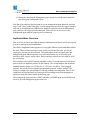
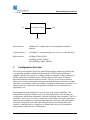
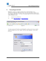
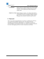
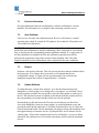
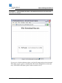
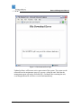
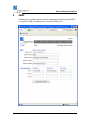
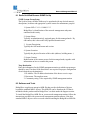
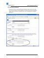
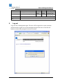
making connections in a high-speed world
Wireless Ethernet Links
Models: GE60, GE60X, FE60, FE60X
AR60, AR60X, GE80, AR80
Network Management Manual
P/N 580-00511
Revision B
July 2006
1 of 34
TM
Network Management Manual
Copyright Notice & Disclaimer
Copyright © 2004 - 2006 BridgeWave Communications. All rights reserved.
No portion of this publication may be reproduced, copied, or distributed without the
written consent of BridgeWave Communications. BridgeWave reserves the right to
update or change the material in this publication at any time without notice. BridgeWave
has made every effort to ensure that the information and the instructions contained in the
publication are adequate and is not responsible for any errors or omissions due to typing,
printing, or editing of this document.
Purchasers of BridgeWave products should make their own evaluation to determine the
suitability of each such product for their specific application. BridgeWave’s obligations
regarding the use or application of its products shall be limited to those commitments to
the purchaser set forth in its Standard Terms and Conditions of Sale for a delivered
product.
This publication has been prepared for professional and properly trained personnel, and
the customer assumes full responsibility when using the information herein.
Safety
CAUTION, WARNING, and DANGER statements have been strategically placed in the
text to alert personnel of possible hazards. These statements must be closely observed.
The following general safety precautions must be observed during all phases of operation
and service of the products covered in this manual. Failure to comply with these
precautions or with specific warnings elsewhere in this manual willfully violates
standards of design, manufacture, and intended use of the product. BridgeWave assumes
no liability for the customer’s failure to comply with these requirements.
•
The products meet all applicable FCC safety requirements for general population
exposure to radio frequency emissions; however, as a general principle it is best
to avoid prolonged, unnecessary exposure to the front of any radio’s transmitting
antenna while it is operating.
•
The outdoor equipment must be properly grounded to provide protection against
voltage surges and built-up static charges. In the event of a short circuit,
grounding reduces the risk of electrical shock.
580-00511, rev B
2 of 34
TM
Network Management Manual
For installations in the U.S.A., refer to Articles 810830 of the National Electrical
Code, ANSI/NFPA No. 70, for information with respect to proper grounding and
applicable lightning protection for copper cables. Additional local electrical code
rules may also apply.
For installations in all other countries, implement protection in accordance with
the safety standards and regulatory requirements of the country and/or locality
where the equipment is to be installed.
•
Do not install or operate this equipment in the presence of flammable gases or
fumes. Operation of any electrical instrument in such an environment constitutes
a definite safety hazard.
•
Do not install substitute parts or perform any unauthorized modification to the
equipment. Changes or modifications not expressly approved by BridgeWave may
void the user’s regulatory authority to operate the equipment.
Product Compatibility
While every effort has been made to verify operation of this product with many different
communications products and networks, BridgeWave makes no claim of compatibility
between its products and other vendors’ equipment.
580-00511, rev B
3 of 34
TM
Network Management Manual
Network Management System (NMS)
Purpose of Manual
The information in this manual is directed to persons who must perform or coordinate the
tasks associated with the process of installing wireless communication devices, and
planning communication network applications.
Prior Knowledge
This manual assumes the user has at least basic experience with and an understanding of
wireless technology and some familiarity with configuring and operating networking
equipment. Preferably, the person installing this equipment fully understands the
information covered in this manual prior to attempting these procedures.
DANGER!
Indicates that personal injury can result if the user does not comply with
the given instruction. A DANGER statement will describe the potential hazard, its
possible consequences, and the steps to perform to avoid personal injury.
WARNING! Indicates that serious damage to the equipment can result if the user does
not comply with the given instruction. A WARNING statement will describe the
potential hazard, its possible consequences, and the steps to perform to avoid serious
equipment damage.
CAUTION!
Indicates that equipment damage, process failure, and/or loss of data can
result if the user does not comply with the given instruction. A CAUTION statement will
describe the potential hazard, its possible consequences, and the steps to perform to avoid
equipment damage, process failure, and/or loss of data.
NOTE: Provides supplementary information to emphasize a point or procedure, or
provides a tip for easier operation.
580-00511, rev B
4 of 34
TM
Network Management Manual
Contact Information
Technical Assistance and Customer Service
BridgeWave distributors and resellers are authorized local service providers and are
responsible for immediate Tier 1 customer support. If problems are not resolved, contact
BridgeWave Customer Service for assistance:
Location:
E-mail:
Tech Support Hot Line:
Fax:
Santa Clara, CA USA
[email protected]
408.567.6906
408.567.0775
Return Material Authorization (RMA)
Should BridgeWave equipment have to be returned for repair or replacement, an RMA
number must be obtained in advance from BridgeWave or the local BridgeWave
distributor. When returning equipment, be sure to write the RMA number on the outside
of the shipping carton.
580-00511, rev B
5 of 34
TM
Network Management Manual
Setting Up a BridgeWave NMS Link in 11 Easy Steps
1. Set computer Ethernet interface to 192.168.0.10 and Subnet Mask 255.255.255.0
then connect the computer to the unit’s copper or fiber network interface (directly
or through a switch). Enter the unit’s default IP address (High Band:
http://192.168.0.2 ; Low Band http://192.168.0.1 into the Internet Explorer or
Firefox address window. Log on as user ‘admin’ with the password ‘adminpass’.
2. Verify radio installation by viewing the Status page:
1. All unit, radio and copper indicators are green on Status page (unless
one or more of the network interface ports is not connected)
2. RSL value should match expected value from the distance chart in the
corresponding installation manual (assuming that the physical
installation and alignment have already been completed).
3. Go to the Setup page and set IP address, mask and gateway to the values provided
by the network administrator. If the final IP address values are not known, leave
the radio units at default.
4. On the Setup page, configure the fiber interface auto negotiation to match the port
settings of your network equipment. Verify settings by checking that all indicators
on the Status page are green.
5. On the Setup page, set Installation Auto-Calibration to disabled (assuming that the
physical installation and alignment have already been completed).
6. On the Setup page, set Link State Propagation to disabled. If this link is to be part
of a redundant path connection, see manual section 4.3 for further instructions.
7. On the Setup page, select which interfaces may exchange data packets with the
management agent. Normally all interfaces should be checked for links used as
part of a private network, however if used to provide public network services, it
may be desirable to limit access to a subset of interfaces for security purposes.
8. Click the Submit button at the bottom of the Setup page. Note that the new setting
will not become effective until the unit is restarted (in Step 10 below).
9. On the password page, set administrator and user passwords and SNMP
community strings (each password set has its own submit button). Password
changes take effect immediately after submitting them. Verify password by
logging out and back in. Note that the administrator username is ‘admin’ and the
username is ‘user’. Normally, factory access should be set to disabled.
10. Print setup, status and maintenance pages and note new passwords.
580-00511, rev B
6 of 34
TM
Network Management Manual
11. Restart the unit from the Maintenance page or power-cycle the unit to make the
new Setup page settings take effect.
Note that if the end user does not want to use the management agent functions, perform
steps 1 and 2 then, on the Setup page, restrict management access to the copper interface
only and set installation auto calibration to disabled, restart the unit from Maintenance
page, and leave the copper port disconnected. There will now be no access to the
management agent until the copper port is reconnected.
Implementation Overview
This overview section is provided for network administrator reference and is not required
in order to perform typical installations.
The NMS is implemented through the use of a gigabit Ethernet switch embedded within
the units. There are three interfaces to the switch: one for the fiber port, one for the
copper port, and one for the radio port. The switch allows both user application and
management agent Ethernet packets to be delivered from/to any of the switch port
interfaces (fiber, copper, and/or radio). Packet and byte statistics are provided for all of
the switch ports.
The switch provides a MAC learning capability with a 15-second timeout for all unicast
packets, however multicast packets are not learned. The switch supports the maximum
standard Ethernet frame size (1518 bytes, or 1522 bytes for 802.1q VLAN-tagged
packets); the switch does not support non-standard oversized “jumbo” packets. The
switch is configured to pass through VLAN tags without processing them. Port VLAN
capabilities are used internally to restrict packet forwarding from/to the management
agent port using the feature found on the Setup page.
The management agent provides a PING responder, an SNMP agent and an HTML web
server to provide management pages to the user.
580-00511, rev B
7 of 34
TM
Network Management Manual
Fiber
Internal BridgeWave Switch
Radio
Copper
Fiber Interface:
1000Base-SX, configurable for auto-negotiation enabled or
disabled
Copper interface:
10/100Base-T, auto-negotiating, auto-cross-over cable detection
Radio interface:
100Mbps (FE60, FE60X)
1000Mbps (GE60, GE60X)
100/1000Mbps (AR60, AR60X)
1.
Configuration Overview
The wireless link should be physically installed following the instructions found in the
corresponding installation manual provided with the link. When the installation is
complete, the units are ready to be configured using a workstation or laptop running an
HTML web browser. BridgeWave has verified operation with current versions of
Microsoft Internet Explorer and Mozilla Firefox. The easy-to-use browser interface
allows you to configure the network management agent and physical interfaces, display
link status, set passwords, obtain port statistics, and perform maintenance operations. At a
minimum, the user should ensure that passwords and other security parameters are
appropriately set.
The management agent supports two types of users, with varying capabilities. The
Administrator (username=’admin’) may view status and statistics, view/modify unit
configuration, and perform maintenance functions (including software update). The User
(username=’user’) may view status, configuration, and statistics, but is prevented from
modifying unit configuration or performing maintenance functions. Note that multiple
users may concurrently access the radio management agent from different browser
windows. If multiple users are logged on as Administrator, they are all permitted to
independently modify the unit’s configuration.
580-00511, rev B
8 of 34
TM
Network Management Manual
2.
Connecting to the Unit
BridgeWave products are shipped with the factory default IP address set to
192.168.0.2 for high band units and 192.168.0.1 for low band radios. Configure your
PC (IP Address 192.168.0.3 – 192.168.0.254, Subnet Mask 255.255.255.0) to connect
with the BridgeWave unit.
2.1
2.2
Launch your web browser.
Enter http://192.168.0.1 or http://192.168.0.2
Figure 2-1
2.3 After entering the IP address of the BridgeWave radio unit, the browser should
display the logon screen; enter ’admin’ as the user and ‘adminpass’ as the initial
password.
Figure 2-2
580-00511, rev B
9 of 34
TM
Network Management Manual
3.
Status Web Page
After logging on, the Status screen will be displayed. The navigation bar across the
top of the screen provides links to the various management functions:
•
•
•
•
•
•
Status – display identification information and status of the unit and the
unit’s interfaces
Setup – configure the management agent and physical network interfaces
Passwords – set/change passwords and enable/disable factory access to the
unit.
o Default username/passwords are:
User: user/userpass
Administrator: admin/adminpass
Statistics – display Ethernet traffic statistics for physical port interfaces
Maintenance – perform an auto-calibration, soft restart or update software
Logout – terminate the management session from this browser window
The Status page shows basic unit information including model and serial numbers, as
well as the current state of the unit and its physical interfaces. Green, yellow and red
status indicators provide a quick visual summary of the unit’s operating condition.
Under normal operating conditions, all indicators should be green, unless one of the
network interface ports is not in use. Red indicators signify unit failures, unconnected
network interfaces, or abnormal operating conditions. Yellow indicators signify
marginal operating conditions, which may impact unit operation. The displayed
information is updated with every refresh of the Status page and does not
automatically update.
580-00511, rev B
10 of 34
TM
Network Management Manual
Figure 3-1 Status Page
580-00511, rev B
11 of 34
TM
Network Management Manual
3.1
Unit
Model/Serial: The model and serial number identify the unit and are required for any
interaction with BridgeWave customer support.
Transmit Radio Band: Indicates the frequency band of the radio’s transmitter. A
link consists of one low-band and one high-band radio.
Up time: Time since last unit restart or power cycle
Input Voltage: Voltage present at unit power input connector
o Green:
o Red:
>= 16 volts
< 16 volts
Temperature: Temperature within unit enclosure
o Green:
o Yellow:
3.2
within specification (-20C to 75C) (-4F to 167F)
at operating limit
Radio
Link up: Speed and state of radio interface
o Green:
o Yellow:
o Red:
link is up, error-free
link is up, but not error-free
link is down
Receive signal level: Signal level in dBm and voltage present at unit test point
For 1000Mbps link speed:
o Green:
>= -51dBm
o Yellow: between -51 and -54dBm
o Red:
< -54dBm
For 100Mbps link speed:
o Green:
>= –61dBm
o Yellow: between -61 and -64dBm
o Red:
< -64dBm
580-00511, rev B
12 of 34
TM
Network Management Manual
Transmitter temp: Temperature of the radio transmitter
o Green:
o Yellow:
within specification (-20oC to 75oC) (-4F to 167F)
at operating limit
Packets received: Number of packets received by the radio interface since last
refresh of the management interface from any active user session
o Green:
o Yellow:
no packet errors since last refresh
one or more packet errors since last refresh
Link Utilization: Percentage of total link capacity in use. This value is calculated
once every minute and displayed until the next calculation period.
3.3
Fiber
Link up: Speed and state of auto negotiation setting of fiber interface
o Green:
o Red:
port is up
port is down
Packets received: Number of packets received by the fiber interface since last refresh
of the management interface from any active user session.
o Green:
o Yellow:
no packet errors since last refresh
one or more packet errors since last refresh
Link Utilization: Percentage of total link capacity in use. This value is calculated
once every minute and displayed until the next calculation period.
3.4
Copper
Link up: Speed and duplex of copper interface
o Green:
o Red:
port is up
port is down
Packets received: Number of packets received by the copper interface since
last refresh of the management interface from any active user session.
o Green:
o Yellow:
no packet errors since last refresh
one or more packet errors since last refresh
Link Utilization: Percentage of total link capacity in use. This value is calculated
once every minute and displayed until the next calculation period.
580-00511, rev B
13 of 34
TM
Network Management Manual
4.
Setup Page
On the Setup page you can view or configure the radio interface, fiber network
interface and management agent settings. The page is split into two separate parts
with the left site of the page allowing for changes to the configuration and the right
side of the page displaying the currently effective values. Current active values are
displayed in red once new values have been submitted, pending a system restart. All
values will be displayed in black after the restart has completed. The following items
can be configured on the Setup page:
•
•
•
•
•
•
Adaptive rate setup: select AdaptRate, 1000 or 100Mbps (Available only for
AR60,AR60X , AR80)
Installation auto-calibration behavior
Fiber interface auto-negotiation and flow-control parameters
Management agent IP configuration
Enable or disable Link State Propagation.
Enable or disable access to the management agent through each of the
network interfaces, (at least one must be selected).
580-00511, rev B
14 of 34
TM
Network Management Manual
Figure 4-1 Setup Page
580-00511, rev B
15 of 34
TM
Network Management Manual
4.1
AdaptRate (AR products only)
The operation mode of the AR60(X) and AR80 product can be set to automatically
switch between 1000 and 100Mbps depending on the receive level of the radio. This
is the default setting for the radio, but it is also possible to force an AR radio to be
fixed to 1000 or 100Mbps. This field is present only for AR60(X) and AR80 models.
4.2
Installation auto-calibration
Installation auto-calibration is enabled as the factory default. With this setting, the
radio will perform an auto-calibration every time the radio is power cycled with the
fiber connection down, followed by the fiber connection changing from down to up.
After the physical installation and alignment procedure is complete, this should
normally be changed to disabled.
4.3
Fiber Interface (GigE)
The fiber interface for the radio units (whether operating in 100 Mbps or 1000 Mbps
mode over the air) is 1000Base-SX (850nm multi-mode). The only setting that can be
changed is to enable or disable auto-negotiation. The units are set with autonegotiation enabled as the factory default. It is important that the BridgeWave radio
and the customer network equipment interfaces be configured identically; both
interfaces should be configured to auto-negotiate or else both should be configured to
not auto-negotiate.
Note: When auto-negotiation is disabled on the fiber interface, then flow-control will
also be disabled. If the radio and the network equipment are configured differently, it
is likely that a connection will not be established over the fiber.
4.4
Management Agent
This section provides information about the management agent MAC address and
allows for the configuration of its IP address, subnet mask and default gateway. These
values are normally provided by the network administrator.
IP address:
Allows for the configuration of the IP address for the
management agent. The factory default for the high-band
radio is 192.168.0.2 and for the low-band radio is
192.168.0.1.
DHCP:
Checking this box enables the unit to receive an IP address,
subnet mask and default gateway from the network’s
580-00511, rev B
16 of 34
TM
Network Management Manual
DHCP server. Un-checking the box disables the DHCP
function.
Subnet mask:
The subnet mask can be configured by picking the desired
value from the pull-down menu.
Default Gateway:
Sets the default gateway address for this radio. Use
‘0.0.0.0’ if no default gateway is to be used.
4.4
Link State Propagation
Enable or disable Link State Propagation (LSP). LSP is normally disabled except in
redundant link configurations or when it is necessary to quickly signal external
network equipment when link failures occur. In redundant link configurations LSP
can be enabled to allow for fast switchover if a radio link failure occurs. When
enabled, LSP turns off the transmit laser on the radio fiber interface when the radio
link is down. This in turn allows the external network equipment to rapidly switch
application traffic to another available (redundant) interface, assuming that the
network equipment supports this functionality (generally supported on enterprise and
network backbone class switches and routers).
4.5
Management Access
As a default, management agent access is enabled on all interfaces. It is often
desirable to restrict agent access for security purposes. One interface must be enabled
at all times to ensure access to the unit if troubleshooting becomes necessary.
4.6
Activity buttons
Load Current:
580-00511, rev B
Displays the current operating values in the data entry
fields of the page. These are the values as of the last unit
restart and do not reflect any changes that have been
submitted pending a future system restart. In order to
reverse the effect of recently submitted configuration
changes, it is necessary to click load current followed by
clicking submit new values.
17 of 34
TM
Network Management Manual
Load Defaults:
Displays the factory default settings in the data entry fields
of the page. These settings will only become active if the
submit new values button is then clicked, followed by a
system restart.
Submit New Values: Submits changes to memory. Any changes made without
clicking this button will be lost upon leaving the Setup web
page. In order to activate any submitted changes from the
Setup page, the unit must be restarted or power cycled.
5. Passwords
This web page allows the Administrator to set the User, Administrator and Factory
Access passwords and SNMP community names. The changes take effect
immediately upon clicking the Submit buttons. It is important to remember the
passwords that have been assigned to the unit. If a password is forgotten, it cannot be
recovered; if this happens please refer to the Factory Reset section below.
580-00511, rev B
18 of 34
TM
Network Management Manual
Figure 5-1 Password Page
580-00511, rev B
19 of 34
TM
Network Management Manual
5.1
User
Permits viewing of unit status, configuration parameters and statistics. Does not
permit modification of any parameter, setting passwords or performing maintenance
functions. The user password can be set and recovered by the administrator. The
factory default user name password combination is: user/userpass
Password:
The password is case-sensitive and can have 0 to 16
alphanumeric characters.
Confirm Password:
Repeat the same password; keep in mind that the password
is case sensitive.
5.2
Administrator
Permits full access to unit, including configuration and maintenance. In order to
recover a lost administrator password a hard reset I required. This will reset the unit
to factory default values and requires a complete reconfiguration of the unit. The
factory default user name and password combination is: admin/adminpass
Password:
The password is case-sensitive and can have 0 to 16
alphanumeric characters.
Confirm Password:
Repeat the same password, keep in mind that the password
is case sensitive.
5.3
Factory Access
Permits factory service personnel to access the unit, including factory-only internal
settings. In order for service personnel to access unit, feature must be enabled and the
administrator needs to set and provide the assigned password.
Password:
The password is case-sensitive and can have 0 to 16
alphanumeric characters.
Confirm Password:
Repeat the same password, keep in mind that the password
is case sensitive.
Factory Access:
Scroll menu to choose between enable and disable, default
is for the access to be disabled.
NOTE: The administrator should only enable factory access for the time of active
access by factory service personnel.
580-00511, rev B
20 of 34
TM
Network Management Manual
5.3
Communities
Communities: The community strings is case-sensitive and can have 0-16
alphanumeric characters. Permits SNMP Manager to access unit using community
strings. The default community strings are as follows:
Read Only: public
Read Write: private
CAUTION!
As part of the initial setup, if you do not intend to utilize the SNMP
function, it is good practice to change the community strings to non-default values. This
will prevent users from accessing the SNMP agent.
6.
Statistics
Allows the viewing of receive and transmit Ethernet packet statistics for all embedded
Ethernet switch interfaces. This is a major source of troubleshooting information for
the system. These values allow the user to see where packets are dropped due to
corrupted or invalid contents, determine the flow of packets between the interfaces,
and determine the rate that data is moving through the system.
Note: that ‘Receive’ and ‘Transmit’ are relative to the switch port; e.g., a packet
transmitted on the fiber interface is a packet sent from the switch to the user’s
network equipment.
The statistics page has an automatic refresh function, which can be enabled/disabled
by checking/unchecking the check box at the bottom of the page. When the automatic
refresh box is checked the page will be updated every 15 seconds.
The clear button at the bottom of the statistics page will clear all packet counters in
the radio.
580-00511, rev B
21 of 34
TM
Network Management Manual
Figure 6-1 Statistics Page
580-00511, rev B
22 of 34
TM
Network Management Manual
6.1
Receive & Transmit
Good Octets:
An octet is a sequence of eight bits. Since a byte is not
eight bits in all computer systems, octet provides an
unambiguous term.
Total good packets:
Total number of packets without errors received. For the
transmit direction this is expressed as total packets sent,
since only good packets are sent.
Unicast:
Total number of unicast packets. Unicast packets are
packets addressed to a single host on a LAN.
Broadcasts:
Total number of broadcast packets. Broadcast packets are
packets addressed to all hosts on a LAN.
Multicasts:
Total number of multicast packets. Multicast packets are
packets addressed to a subset of hosts on a LAN.
Pauses:
Pause frames are sent if flow control is enabled and a port
needs to temporarily stop the flow of incoming packets.
Undersized:
Number of packets received that are smaller then 64 bytes.
Fragments:
Number of partial packets received.
Oversized:
Number of packets received that exceed 1518 bytes (or
1522 bytes with an 802.1q VLAN tag). These errors are
caused either by damaged packets or by user network
equipment being configured to transmit jumbo frames.
Jabber errors:
Packets received after a pause frame has been sent to the
remote end. It is likely that flow control is disabled at the
remote end and enabled at local end of the connection; this
problem is most easily solved by setting both ends of the
link to either have flow control enabled or disabled.
PHY errors:
Receive errors on the physical interface.
580-00511, rev B
23 of 34
TM
Network Management Manual
CRC errors:
Short for Cyclic Redundancy Check, CRC is a method of
detecting errors in data transmission. A CRC is data that is
sent with a block of data, that when received can be used to
verify that all data was received correctly. CRC errors
typically indicate physical defects in fiber or copper
cabling, or poor receive signal quality on a radio link. One
or less CRC error every 20 minutes on a fully-loaded
1000Mbps link would equal a bit error rate of under 10-12
and is considered excellent performance for fiber or radio
connections. One CRC error every 2 minutes would equal a
bit error rate of 10-10 on a 100Mbps copper connection,
which complies with 100Base-TX specifications. While
higher error rates should normally only be seen during
short periods of heavy rain downpours, most LAN
applications can easily tolerate up to 10-8 bit error rates
without noticeable degradation.
Collisions:
Total number of collisions detected. Collisions indicate that
more than one device is transmitting packets to an Ethernet
hub at the same time, and will normally be detected by the
device itself and be re-transmitted. Collisions should not
occur when devices are connected through Ethernet
switches.
580-00511, rev B
24 of 34
TM
Network Management Manual
7.
Maintenance – Control unit operation
Figure 7-1 Maintenance Page
580-00511, rev B
25 of 34
TM
Network Management Manual
7.1
Version Information
Provides information about the serial numbers, software and hardware versions
installed. This information is very helpful when contacting customer service.
7.2
Auto-Calibrate
Unit receiver will enter auto-calibration mode. Receiver will return to a normal
operating state within 30 seconds for GE products, 90 seconds for FE products and
120 seconds for AR products.
CAUTION!
For the first auto calibration after unit installation, it is necessary to
perform the auto-calibration by initially establishing a fiber connection to a powered-up
unit, as described in the corresponding product installation manual. If a copper-only (i.e.
no fiber) installation is intended, the first auto-calibration operation must still be
performed by temporarily using a fiber switch or fiber loopback cable. This fiber
loopback should be removed immediately after completion of the auto-calibration.
7.3
Restart
Performs a soft restart of the unit. This will activate the latest changes submitted from
the Setup page. If no changes have been made it will maintain the current
configuration settings. A restart will not stop data transfer, but will make the
management agent inaccessible for approximately 1-2 minutes.
7.4
Update Software
To obtain the latest version of the software, go to the download section of the
BridgeWave website at http://www.bridgewave.com/support. You will find a list of
software updates available for your product, where the latest update is on the top of
the list. The download consists of a dated zip file that includes the product software,
the corresponding user manual and the release notes for the package.
Download the zip file and extract the files into a new folder on your hard drive.
Access the BridgeWave unit you want to update, go to the Maintenance page and
provide the unit with the path to the (2) .bin files on the hard drive one at a time and
click the download button. The file download, file integrity check and installation will
take approximately two minutes for file <SysProgLdr.bin> and 10 minutes for file
<BwProg.bin>. When it has completed, the browser will display a success or failure
indication. If no indication is received after ten minutes, please restart the download
process.
580-00511, rev B
26 of 34
TM
Network Management Manual
CAUTION!
Do not change file names. This upgrade process may fail if any of the
files names are changed.
Figure 7-2 File Download Success Page
If you receive a failure indication, please verify the file name and retry the download.
If the failure repeats, please re-download the file from the BridgeWave website and
retry. If the failure still repeats, please contact customer service.
580-00511, rev B
27 of 34
TM
Network Management Manual
Figure 7-3 File Download Error Page
Updated software will become active upon restart of the system. The system can be
restarted from the maintenance page or by power cycling the unit. Note that the
management agent will not be accessible for 1-2 minutes after restarting the unit,
even though data traffic will flow over the link immediately.
580-00511, rev B
28 of 34
TM
Network Management Manual
8.
SNMP
All BridgeWave products that are network management enabled provide SNMP
v1 support for MIB-2 and BridgeWave enterprise MIB objects.
580-00511, rev B
29 of 34
TM
Network Management Manual
8.1 Radio Unit Web Browser SNMP Set Up
SNMP System Group Setup
The System Group variables fields may be populated with any desired name(s),
descriptions, locations and appropriate system contact for maintenance purpose.
1. System OID: 1.3.6.1.4.1.6080.1.2.3
BridgeWave’s identification of the network management subsystem
contained in this entity.
2. System Name:
Typically an administratively assigned name for this managed node. By
convention, this is the node's fully-qualified domain name.
3. System Description:
Typically the full model name and version
4. System Location:
Typically the physical location of this radio (address, building name…)
5. System Contact:
Identification of the contact person for this managed node, together with
information on how to contact this person
Trap Destination
Enter the information for the SNMP management station to which trap messages
should be sent. The three fields listed below are required for proper configuration
of each desired trap destination(s).
1. IP Address: The IP address destination of the host to receive traps
2. Host name: The trap host name
3. Community string: Value required by SNMP management station
8.2 Software and Tools
BridgeWave supplies an enterprise MIB file that provides definitions of objects
beyond the standard MIB-2 objects. This MIB file can be found on the CD that is
included with the product and on BridgeWave’s website under the Support section.
To install the BridgeWave MIB file on your network management station, follow the
instructions provided with your network management station software. Note that
standard MIB-2 objects can be accessed without installing the BridgeWave MIB file.
580-00511, rev B
30 of 34
TM
Network Management Manual
8.3 Connecting to Network
Ensure that you have entered the desired community string values on the radio
unit’s Password page (see below) and then verify that your network management
station software can browse the MIB-2 and, if used, the BridgeWave enterprise
MIB objects.
580-00511, rev B
31 of 34
TM
Network Management Manual
8.4 SNMP MIB Objects
Supported MIB-2 Groups
OID
1.3.6.1.2.1.1
1.3.6.1.4.1.2
1.3.6.1.4.1.3
1.3.6.1.4.1.4
1.3.6.1.4.1.5
1.3.6.1.4.1.6
1.3.6.1.4.1.7
1.3.6.1.4.1.8
1.3.6.1.4.1.10
1.3.6.1.4.1.11
Name
system
interfaces
at
ip
icmp
tcp
udp
egp
transmission
snmp
Interfaces: MIB-2 interface table is always populated with the following five
entries. 1 = Loop-back, 2 = Management port 3 = Copper port, 4 = Fiber port and
5 = Radio port
BridgeWave Enterprise MIB Objects
Name
brwaveUnitSn
brwaveUnitModel
brwaveTrapCount
brwaveRadioTxBand
OID
1.3.6.1.4.1.6080.2.1
1.3.6.1.4.1.6080.2.2
1.3.6.1.4.1.6080.2.6
1.3.6.1.4.1.6080.3.1.2.1
brwaveRadioFactoryRate
brwaveRadioInVoltage
brwaveRadioUnit
Temperature
brRadioTxTemperature
brwaveRadioRSL
brwaveRadioRSLVoltage
1.3.6.1.4.1.6080.3.1.2.3
1.3.6.1.4.1.6080.3.1.3.1
1.3.6.1.4.1.6080.3.1.3.2
Unit Model Number
Traps generated by a given unit
Radio’s transmitting frequency
band
Radio’s operating data rate
Radio’s Input voltage
Radio’s internal unit temperature
1.3.6.1.4.1.6080.3.1.3.3
1.3.6.1.4.1.6080.3.1.3.4
1.3.6.1.4.1.6080.3.1.3.5
Radio’s transmitter temperature
Receive Signal Level
Corresponding Voltage of RSL
Description
Units serial number
BridgeWave Enterprise MIB Traps
Unit Temp
Abnormal
Unit Temp Normal
Transmitter Temp
Abnormal
Transmitter Temp
Normal
RSL Major
580-00511, rev B
Internal Temp outside of –20 to +75 degrees Celsius range
Internal Temp restored to normal range
Transmitter outside of –20 to +75 degrees Celsius range
Transmitter Temp restored to normal range
RSL drops below critical level
32 of 34
-64dBm
<-54dBm
Depending on AR
TM
Network Management Manual
9.
-64 to –
61dBm
>-61dBm
-54 to –to
-51dBm
>-51dBm
Operating mode
Depending on AR
Operating mode
Depending on AR
Operating mode
RSL Minor
RSL drops below the desired level
RSL Normal
RSL Level within expected range
Radio Link Error
Radio Link Error
Free
When radio link has taken more than 1000 errors in 4 seconds
When radio link returns to an error-free state for at least 4 seconds
Log out
Logs user out of management agent. The user will be required to re-enter username
and password to regain access to the management agent. Be sure to close the web
browser session when prompted to increase security.
580-00511, rev B
33 of 34
TM
Network Management Manual
10.
Factory (Hard) Reset
If the unit’s Administrator password or IP configuration is forgotten, it will be
necessary to perform a hard reset to return the unit to its factory default configuration
before you can re-connect with the unit’s network management web pages. In order to
reset the unit to factory configuration, it is required to have physical access to the
unit’s copper data port (RJ-45 jack) or cable and the unit’s power cable. This
operation will require at least a three-minute interruption of data traffic through the
unit.
Each BridgeWave unit is shipped with a hard reset box that can be used to return the
unit to its default factory configuration. First power down the unit, then connect the
hard reset box via a straight-through (standard) Ethernet cable at least 3m long to the
copper (RJ45) port on the unit. If a cable is already running to the RJ-45 port of the
unit, the reset box can simply be connected to the other end of this cable
Note: Reconnect power to the unit and wait a minimum of 70 seconds, but less than
90 seconds before disconnecting the hard reset box (leave the Ethernet cable in place
for 2 more minutes). The unit will then begin its normal restart cycle, and the
management agent will normally become accessible within approximately 2 minutes
using the default IP configuration and default usernames, passwords and community
strings. Note that this may take longer than a normal restart operation.
If you do not have access to the hard reset box supplied with the unit, you can create your
own “hard reset cable” by cutting off one end of a standard Ethernet patch cable (at least
3m in length) and then stripping and connecting together the two wires of the twisted pair
going to pins number 3 and 6 of the RJ-45 plug on the other end
of the cable; these are typically the wires from either the
orange/white-orange or green/white-green pairs, but this is not
guaranteed to be the case. All other wires must be left unterminated. Use this hard reset cable as a substitute for the hard
reset box and Ethernet cable described above. Instead of disconnecting the hard reset box
(as in the previous procedure), disconnect the wires going to pins 3 and 6 from each other
and leave the cable in place for the additional 2 minutes; it is important not to remove the
cable from the unit until the process is complete.
580-00511, rev B
34 of 34