1
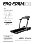
PRO.FORM'835Q-IQ
::.:
I
MI
I rl
.......
-
USER'S MANUAL
Model No. 831.299480
Serial No.
Find the serial number in the location
shown below. Write the serial number
in the space above for reference.
Number
Decal
I='Q
u
i p
M
H E:LPLIN
E: NT
F----!
1-800-736-6879
BEARB, ROEBUCK AND CO,
HOFFMAN ESTATES, IL 60179
Patent Pending
PRO.FORM 8 3 5 Q T
I_ _1 _ _
I
TABLE OF CONTENTS
IMPORTANT PRECAUTIONS .................................................................
BEFORE YOU BEGIN .......................................................................
ASSEMBLY ...............................................................................
OPERATION AND ADJUSTMENT
.............................................................
HOW TO FOLD AND MOVE THE TREADMILL
..................................................
TROUBLE-SHOOTING
.....................................................................
CONDITIONING GUIDELINES ...............................................................
PART LIST ...............................................................................
ORDERING REPLACEMENT PARTS ..................................................
FULL 90-DAY WARRANTY ...........................................................
Note: An EXPLODED DRAWING is attached in the center of this manual.
°
"
2
3
5
6
8
19
20
22
23
Back Cover
Back Cover
IMPORTANT
PRECAUTIONS
lZ:
Unplug
aloft switch to
hen tile treadmill is not in
wearing
only stockings,
or in sandals.
use. (Sea the draw ng on page 5 for the oeation of the on/off switch.)
I0. When connecting the power cord (see page 8),
plug the power cord into a surge suppressor
(not included) and plug the sui'ge suppressor
into a gr0unded c_rcuit capable of car:rying 15
or more amps. No other appliance should be
on the salne'circuit.
Donot use _n e>(tensi0n
18 Do not attempt to raise, lower, or move the
treadmill unt
t s proper y assembled (See
ASSEMBLY on page 6, and HOW TO FoLD
AND MOVE THE TREADMILL on page 19.) You
must be able to safely lift 4S pounds (20 kg) in
cord.:
order to ra se,, ower, Or move the treadmill.
11.Useonlyasnge-outetsurgesuppressorthat
is UL 14_19listed as a transient Voffage surge
suppressor (TVSS),The surge s(ippresso_
......
19 Do not change the nc neofthetreadm
plac ng objects under the treadmill.
: •
" ••
.
3
by
:i
The decals shown below have been placed on your treadmill.
please call our toll-free HELPLINE to order a free replacement
Apply the decal in the location shown.
Note: This decal is shown at 38% of actual size.
If a decal is missing, or if it is not legible,
decal (see the front cover of this manual).
BEFORE YOU BEGIN
Thank you for selecting the revolutionary PROFORIVP
835QT treadmill. The 835QT treadmill combines advanced technology with innovative design to help you
get the most from your exercise program in the convenience and privacy of your home. And when you're not
exercising, the unique 835QT can be folded up, requiring less than half the floor space of other treadmills.
Monday through Saturday, 7 a.m. until 7 p.m. Central
Time (excluding holidays). To help us assist you,
please note the product model number and sedal number before calling. The model number of the treadmill
is 831.299480. The serial number can be found on a
dec_ attached to the treadmill (see the front cover of
this manual for the location).
For your benefit, read this manual carefully before
using the treadmill, If you have addi_tionalquestions,
please call our toll-free HELPLINE at 1-800-736-6879,
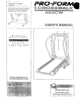
Before reading further, please review the drawing
below and familiarize yourself with the parts that are
labeled.
Book Holder
Water Bottle
Holder (Bottle
not included)
Console
Pulse Sensor
Handrail
Lock Knob,
RIGHT SIDE
LEFT SIDE
On/Off Switch
Circuit
Breaker
Walking Belt,
Foot F
Powe" Cord
Front
Wheel
Rear Roller
--
Adjustment Bolts
5
Cushioned Walking Platform
ASSEMBLY
Assembly requires two people. Set the treadmill in a cleared area and remove all packing materials. Do not
dispose of the packing materials until assembly is completed. Assembly requires your own Phillips screwdriver (_2}_==-.
Note: The underside of the treadmill walking belt is coated with high-performance lubricant. During shipping, a
small amount of lubricant may be transferred to the top of the walking belt or the shipping carton. This is a normal
condition and does not affect treadmill performance. If there is lubricant on top of the walking belt, simply wipe off
the lubricant with a soft cloth and a mild, non-abrasive cleaner.
1. With the help of a second •person, carefully raise the
treadmill to the upright position.
While a second person tips the treadmill to one side
slightly and holds it, insert one of the Extension Legs
(103) into the treadmill as shown. Make sure that the
Extension Leg is turned so the Base Pad (97) is on the
bottom.
103
Next, tip the treadmill to the other side and insert the
other Extension Leg (not shown) in the same way. Lower
the side of the treadmill so that both Extension Legs
(103) are resting flat on the floor.
97
2. With the help of a second person, carefully lower the
treadmill frame and then tip the Uprights (82) down as
shown. Make sure that the Extension Legs (103) remain in the Uprights.
Attach each Extension Leg (103) with two of the four
Screws (101) and a Base Pad (126) as shown.
Note: One replacement Base Pad (126) and Spacer (not
shown) are included. If a Base Pad (126) becomes worn
and needs to be replaced, use the replacement Base
Pad. If a Thick Base Pad (97) needs to be replaced, use
the replacement Base Pad with the Spacer.
7101
3. With the help of a second person, carefully tip the
Uprights (82) back to the vertical position.
3
Attach the Latch Assembly (9) to the left Upright (82) with
the two 1/2" Screws (89).
6
89
4. Find the plastic tie inside the'post on the left Updght
(82). Insert the plastic tie through a Handrail Extension
•(85) and insert the Handrail Extension into the post as
shown. Make sure that the indicated holes are on top. If
necessary, tap the Handrail Extension with a rubber mallet to fully insert it, Attach the Handrail Extension with
three of the eight Small Screws (76) as shown.
4
Post
76
Identify the Left Foam Grip (110), which has a large
cutout in the right side. Slide the Left Foam Gdp as far as
possible onto the post on the left Updght (82).
110
85
Plastic Tie
5. Make sure that the Left Foam Grip (110) is flush with the
Console Base (87) as shown. Tighten a Small Screw (76)
into the side of the Left Foam Grip as shown.
5
87
\
Attach the Right Foam Grip (not shown) and the other
Handrail Extension (not shown) as described in step 4
and this step. Note: There is no plastic tie in the dght
side.
6. Refer to drawing 6a. Locate the left Rear Foot (59) on
the treadmill. If the left Rear Foot touches the floor, go to
step 7. If there is a space between the left Rear Foot and
the floor, follow the instructions below.
110
6a
Hold the treadmill firmly with both hands, and raise the
treadmill to the storage position as described on page 19.
59
Refer to drawing 6b. Using a phillips screwdriver, remove
the Screw (60), the right Rear Foot (59), and the Rear
Foot Spacer (11) from the treadmill. Reattaoh the right
Rear Foot without the Rear Foot Spacer. Hold the treadmill with both hands, and lower the treadmill as
described on page t 9.
6b
Check the left Rear Foot (59 [see drawing 6a]). If the left
Rear Foot is still off the floor, raise the treadmill and remove the left Rear Foot. Snap the Rear Foot Spacer (11 )
onto the left Rear Foot and reattach the left Rear Foot
and the Rear Foot Spacer. Carefully lower the treadmill.
7. Make sure that all parts are tightened before you use the treadmill. Keep the included allen wrench in a
secure place. The atlen wrench is used to adjust the walking belt (see page 21). To protect the floor or carpet
from damage, place a mat under the treadmill.
7
OPERATION
THE PERFORMANT
AND ADJUSTMENT
LUBE TM WALKING
BELT
Your treadmill features a walking belt coated with
PERFORMANT LUBE TM, a high-performance lubricant.
IMPORTANT: Never apply silicone spray or other
substances to the walking belt or the walking platform. Such substances will deteriorate the walking
belt and cause excessive wear.
This product is for use on a nominal 120-volt circuit,
and has a grounding plug that looks like the plug illustrated in drawing 1 below. A temporary adapter that
looks like the adapter illustrated in drawing 2 may be
used to connect the surge suppressor to a 2-pole
receptacle as shown in drawing 2 if a properly
grounded outlet is not available.
HOW TO PLUG IN THE POWER CORD
[_
_Grounded
Outlet Box
_'-1
Surge Suppressor
_
Fi lil ;',a;j"'" Grounding
Grounding Pin /
Grounded Outlet
'
Pin
_
Gmnnding Plug'"_
Jtlet Box
Adapter
Your treadmill, like any other type of sophisticated
electronic equipment, can be seriously damaged by
sudden voltage changes in your home's power.
Voltage surges, spikes, and noise interference can
result from weather conditions or from other appliances
being turned on or off. To decrease the possibility of
your treadmill being damaged, always use a surge
suppressor with your treadmill (see drawing 1 at
the right).
To purchase a surge suppressor,
PROFORM dealer or call toll-free
Metal Screw
see your local
1-800-366-7278
The temporary adapter should be used only until a
properly grounded outlet (drawing 1) can be installed
by a qualified electrician.
and order part number 146148. Use only a singleoutlet surge suppressor that is UL 1449 listed as a
transient voltage surge suppressor (TVSS). The surge
suppressor must have a UL suppressed voltage rating
of 400 volts or less and a minimum surge dissipation of
450 joules. The surge suppressor must be electrically
rated for 120 volts AC and 15 amps.
The green-colored rigid ear, lug, or the like extending
from the adapter must be connected to a permanent
ground such as a properly grounded outlet box cover.
Whenever the adapter is used it must be held in place
by a metal screw. Some 2-pole receptacle outlet box
covers are not grounded. Contact a qualified electrician to determine if the outlet box cover is
grounded before using an adapter.
This product must be grounded. II it should malfunction or break down, grounding provides a path of least
resistance for electric current to reduce the risk of electric shock. This product is equipped with a cord having
an equipment-grounding conductor and a grounding
plug. Plug the power cord into a surge suppressor,
and plug the surge suppressor into an appropriate
outlet that is properly installed and grounded in
accordance with all local codes and ordinances.
Important: The treadmill
GFCl-equipped
outlets.
is not compatible
with
8
CONSOLE
DIAGRAM
• Incline Display
_7_
•
o
o
o
Displays
o
o
o
o
LED Track
Program Indicators
Displays
u_e
',;"Z"
........
_Jz3
pOW£R JNCUHE
Tl_
Manual/iFIT.com
SEOM
TlUE
$PEEO
Indicators
Note: If there is a thin sheet of clear plastic
on the face of the console, remove it.
....
Key
_i
I _tLt
'
O,_
Speed Buttons
Clip
home stereo, portable stereo, or computer and play
special iFIT.com CD programs (CD's are available
separately). IFIT.com CD programs automatically control the speed and incline of the treadmill as a personal
trainer guides you through every step of your workout.
High-energy music provides added motivation. Each
CD features two different programs designed by certified personal trainers.
In addition, you can connect the treadmill to your VCR
and TV and play iFIT.com video programs (videocassettes are available separately). Video programs offer
the same benefits as !FIT.corn CD programs, but add
the excitement of working out with a class and an instructor-the
hottest new trend at health clubs.
FEATURES
OF THE CONSOLE
The treadmill console offers an impressive array of
features to help you get the most from your exercise.
When the console is in the manual mode, the speed
and incline of the treadmill can be controlled with a
touch of a button. As you exercise, the LED track and
the four displays will provide continuous exercise feedback. You can even measure your heart rate using the
built-in pulse sensor.
Six certified personal trainer programs are also offered.
Each program automaticaUy controls the speed and incline of the treadmill as it guides you through an effective workout.
The console also features advanced iFIT.com interactive technology. IFIT.com technology is like having a
personal trainer right in your home. Using the included
audio cable, you can connect the treadmill to your
With the treadmill connected to your computer, you
can also go to our new internet site at www.iFIT.com
and access even more programs. Choose from a selection of basic programs that interactively control 'the
speed and incline of your treadmill to help you achieve
your personal exercise goals. Or, use !FIT.corn audio
and video programs directly from our intemet site. Visit
www.iFIT.com for complete details.
By adding an optional upgrade module to the treadmili,
you can use virtually endless features from our internet
site. See www.iFIT.com to learn about other iFIT.com
features. To purchase !FIT.corn CO's, !FIT.corn
videocassettes,
or an optional upgrade module,
call toll-free 1-800-735-0768. For information about
other optional accessories,
see page 18.
To use the manual mode of the console, follow the
steps beginning on page 10. To use a personal trainer
program, see page 12. To use !FIT.corn CD or video
programs, see page 15. To use !FIT.corn programs
from our internet site, see page 17.
HOW TO TURN ON THE POWER
g
change the speed of the
AWARNIHG:I_d_
walking belt as desired by
pressing the SPEED Z_
and _7buttons. To change
the speed setting quickly,
press the QUICK SPEED
buttons. Note: After the buttons are pressed, it
may take a moment for the treadmill to reach the
selected speed setting.
Plug in the power cord (see HOW TO PLUG IN
THE POWER CORD on page 8).
B
switch on the front of
the treadmill. Make
sure thethe
on/off
switch
Locate
on/off
is in the on position.
On
Position
I
[_
To stop the walking belt, press the STOP button.
The TIME display will begin to flash. To restart the
walking belt, press the START button or the
SPEED A button.
OSan
onheootras
of the treadmill. Find
the clip attached tO the
'
key, and slide the clip
securely onto the waistband of your clothing.
Test the clip by carefully taking a few steps backward until the key
is pulled from the console. If the key is not
pulled from the console, adjust the position of
the clip as needed.
B
as desired.
To change the
incline of the
_70
0
0
0
0
0
0
0
0
O_
treadmill, press
_owE_ INCLSNE
the INCLINE
buttons. Each
Program Display
I}
J
time a button is
MANUAL
pressed, the incline will change
by 0.5%. The buttons can be held down to change
the incline quickly. Note: After the incline buttons
are pressed, it will take a moment for the treadmill
to reach the selected incline setting.
..... I.........!
Next, insert the key into the console. After a moment, the four displays, the LED track, and various
indicators on the console will light.
Note: The console can display speed and distance in
either miles or kilometers (see SPEED/MIN-MILE DISPLAY on page 11). For simplicity, all instructions in this
manual refer to miles.
g
Change the incline of the treadmill
Note: In the incline display, the first indicator wil!
light when the incline is set at t .5%. The second
indicator will light when the incline is set at 2% or
2.5%, the third indicator win light when the incline
is set at 3% or 3.5%, and so forth.
[_
Insert the key fully into the console.
Follow your progress
the four displays.
with the LED track and
See HOW TO TURN ON THE POWER above.
B
The LED Track--The
LED track represents a
distance of 1/4 mile. As
you exercise, the indicators around the track will
Select the manual mode.
When the key is inserted, the manual
mode will be selected
and the MANUAL indicator will light. If a program has been selected, press the PROGRAM button repeatedly to
select the manual mode.
[_']
light one at a time until
you have completed 1/4
mile. A new lap will then begin.
play--This
display shows
Arrow
the distance that you
have walked or run and
the number of laps you
DISTANCE LAPS
have completed (one lap
equals 1/4 mile). The display will alternate between
one number and the other every seven seconds,
as shown by the arrows in the display.
D,S,ANC 'APSd,s
I.u3
Press the START button or the SPEED ,_ button
to start the walking belt.
A moment after the button is pressed, the walking
belt will begin to move at 1 mph. Hold the handrails
and carefully begin walking. As you exercise,
lO
TIME display--When
the manual mode or an
• iFIT.com program is
I
selected, this display
shows the elapsed time.
When a pemonal trainer
program is selected, this display shows both the
time remaining in {he program and the time remaining in the current segment of the program.
The display will alternate between one number and
the other every seven seconds.
r_
place your
hands on the
metal contacts
on the pulse bar.
Your palms
must be resting
on the upper
contacts, and
your fingers must
be touching the
CALS/FAT CALSI
PULSE display--This
display shows the approximate numbers of
ca/Dries and fat ca/odes
you have burned (see
FAT BURNING on page
22). Every seven seconds, the display will change
from one number to the other, as shown by the arrows in the display. This display will also show
your heart rate when the pulse sensor is used (see
step 6 on this page).
SPEED/MIN-MILE
L
_t_
"
PULSE
123
lower contacts-CALS. FAT¢ALG.
avo|d moving
your hands.
When your pulse is detected, the heart-shaped indicator in the CALS/FAT CALS/PULSE display will
flash steadily and a sedes of dashes (- -) will appear. After a few seconds, your heart rate will be
shown. For the most accurate heart rate reading, continue to hold the contacts for about 15
seconds.
B
display--This display
shows the speed of the
walking belt and your
SPEED
MINI MILE (kin)
current pace (pace is
measured in minutes per
mile). Every seven seconds, the display will
change from one number to the other, as shown
by the arrows in the display.
Stand on the
Measure
foot
rails your
and heart rate, if desired. Sensors
i
When you are finished exercising, remove the
key,
Step onto the foot rails, press the STOP button,
and adjust the incline of the treadmill to the lowest
level. The incline must be at the lowest level
when the treadmill Is raised to the storage position or the treadmill will be damaged. Next,
remove the key from the console and put the key
in a secure place. Note." If the displays and various indicators on the console remain lit after
the key is removed, the console is in the
"demo" mode. Refer to page 18 and turn off the
demo mode.
Note: The SPEED/MIN-MILE display can show
speed in either miles per hour or kilometers per
hour. To find which unit of measurement is se.
lected, hold down the STOP button while inserting
the key into the console.
An "E" for English miles
or an "M" for metric kiloC'
12
meters will appear in the
display. Press the
SPEEDMIN/MILE(kin)
SPEED _ button to
When you are finished using the treadmill, move
the on/oft switch near the power cord to the off
position.
change the unit of measurement. When the desired unit of measurement
is selected, remove and then reinsert the key.
Note: To reset the displays, press the STOP button, remove the key, and then reinsert the key.
11
O
One speed setting and one incline setting are programmed for each segment. When only three seconds remain in the first segment, a series of tones
will sound and the treadmill will automatically adjust to the speed and incline settings for the second
segment.
Insert the key into the console.
See HOW TO TURN ON THE POWER on page
10.
Select one of the personal
trainer
The program will continue in this way until the
TIME display counts down to zero. The walking
belt will then slow to a stop.
programs.
we,+
key is inserted, the
manual
mode will be
selected and
Note: If the speed or incline setting for the current
segment is toe high or too low, you can manually
override the setting by pressing the SPEED or
INCLINE buttons on the console. However, when
the next segment begins, the treadmill will adjust to the next speed and incline settings of
the program.
_ ........................... =,,=+
#,_o ,_,
.....
_,o
'..'mo ,,,',_,,,,
;,_-..,
o
the
MA+
UAL indica-
tor will light.
To select one of the personal trainer programs,
press the PROGRAM button repeatedly until one
of the six personal trainer program indicators
lights.
The console features two low intensity programs,
two medium intensity programs, and two high intensity programs. The profiles on the console
show how the speed and incline of the treadmill
will change during the programs. The numbers
beside the profiles show the maximum speed and
incline settings for the programs. For example, the
upper profile shows that the treadmill will reach a
maximum speed of 4.5 mph and a maximum incline of 5% during the first program.
_1
Press the START button or the SPEED _ button
to start the program.
To stop the program, press the STOP button. The
TIME display will begin to flash. To restart the program, press the START button or the SPEED A
button. To end the program, press the STOP button, remove the key, and then reinsert the key.
_1
Follow your progress
the four displays.
with the LED track and
Refer to step 5 on page 10.
[_"_ Measure your heart rate, if desired.
See step 6 on page 11.
r,_
when the program is completed,
key from the console.
remove the
When the program has ended, make sure that
the treadmill is at the lowest incline level. Next,
remove the key from the console and put it in a
secure place. Note: If the displays and indicators on the console remain lit after the key is
removed, the console is in the "demo" mode.
Refer to page 18 and turn off the demo mode.
A moment after the button is pressed, the treadmill will automatically adjust to the first speed and
incline settings for the program. Hold the handrails
and begin walking.
Each program is divided
into several time
segments of different
lengths. The TIME
display shows both the
time remaining in the program and the time
remaining in the current segment of the program.
When you are finished using the treadmill, move
the on/off switch near the power cord to the off
position.
12
.
_.: : :.:::
::_
;_'_,,:_
"::_._:_:i:-:_!_,,;_?:_
-
"_
!!:!_:_;:'_::!
!!!
To use iFIT.com CD's, the treadmill must be connected to your portable CD player, portable stereo,
home stereo, or computer with CD player. See pages
13 and 14 for connecting instructions. To use iFIT.com
videocassettes,
the treadmill must be connected to
your VCR. See page 15 for connecting instructions. To
use iFIT.com programs directly from our internet
site, the treadmill must be connected to your home
computer. See page 14 for connecting instructions.
HOW TO CONNECT YOUR PORTABLE
HOW TO CONNECT YOUR PORTABLE STEREO
Note: If your stereo has an RCA-type AUDIO OUT
jack, see instruction A below. If your stereo has a
3.5mm LINE OUT jack, see instruction
B. If your
stereo has only a PHONES jack, see instruction
C.
A. Plug one end of the audio cable into the jack on the
front of the treadmill near the power cord. Plug the
other end of the cable into the included adapter. Plug
the adapter into an AUDI 0 OUT jack on your stereo.
A
CD PLAYER
Note: If /our CD player has separate LINE OUT and
PHONES jacks, see instruction
A below. If your CD
player has only one jack, see instruction
B.
i_"_i
i @'[-_
A. Plug one end of the audio cable into the jack on the
front of the treadmill near the power cord. Plug the
other end of the cable into the LINE OUT jack on
your CD player. Plug your headphones into the
PHONES jack.
Audio
!
Adap er 4
Cable
' ::.:-:.:::'_
B. Plug one end of the audio cable into the jack on the
front of the treadmill near the power cord. Plug the
other end of the cable into the LINE OUT jack on
your stereo.
B
!!::!,!!!:i!:i:i
!:::!!!:,:
phonde;
.......
i .....
Audio
i _) _]
=:
!---,-:-:-:-:-:---!
__=_
B. Plug one end of the audio cable into the jack on the
front of the treadmill near the power cord. Plug the
other end of the cable into a 3.5ram Y-adapter
(available at electronics stores). Plug the Y-adapter
into the PHONES jack on your CD player. Plug your
headphones into the other side of the Y adapter.
Cable
C. Plug one end of the audio cable into the jack on the
front of the treadmill near the power cord. Plug the
other end of the cable into a 3.5ram Y-adapter
(available at electronics stores). Plug the Y-adapter
into the PHONES jack on your stereo. Plug your
headphones into the other side of the Y-adapter.
! "
i L_ (_)
:i
3.5mm
AUdcableO y -adapter_
Headphones --_caE:_
13
_
HOW TO CONNECT
YOUR HOME STEREO
HOW TO CONNECT
YoUR (_OMPUTER
Note: If your stereo has an unused LINE OUT jack,
see instruction A below. If the LINE OUT jack Is
being used, see Instruction B.
Note: If your computer has a 3.5mm LINE OUT jack,
see Instruction'A. If your computer has only a
PHONES jack, see instruction B.
A. Plug one end of the audio cable into the jack on the
front of the treadmill near the power cord. Plug the
other end of the cable into the included adapter.
A. Plug one end of the audio cable into the jack on the
front of the treadmill near the power cord. Plug the
other end of the cable into the LINE OUT jack on
your computer.
Plug the adapter into the LINE OUT jack on your
stereo,
A
"
"l_"(_'_i
:_
IF
_
i
Audio
_]
Cable
_
w
F@"_
i A _
Audio
:
Adapter---_
j
II
1
Cable
B.
B. Plug one end of the audio cable into the jack on the
front of the treadmill near the power cord. Plug the
other end of the cable into the included adapter.
Plug the adapter into an RCA adapter (available at
electronics stores). Next, remove the wire that is
currently plugged into the LINE OUT jack on your
stereo and plug the wire into the unused side of the
RCA adapter. Plug the RCA adapter into the LINE
OUT jack on your stereo.
Plug one end of the audio cable into the jack on the
front of the treadmill near the power cord. Plug the
other end of the cable into a 3.5mm Y-adapter
(available at electronics stores). Plug the Y-adapter
into the PHONES jack on your computer. Plug your
headphones or speakers into the other side of the
Y-adapter.
B
U
B
_=
@@, Audio
=
i Cable
Headphones/Si
RCA
i_-]"_
]
Audio
i_ _
!
Cable
Adapte¥Adapter
Wire removed from -_-_..-{:]_._
LINE OUT jack
14
3.5mm
Y-adapter
__,:_ _$$BS_'_
HOW TO CONNECT YOUR VCR
Note: If your VCR has an unused AUDIO OUT jack,
see instruction A below. If the AUDIO OUT jack is
being used, see instruction B. If you have a TV
with a built-in VCR, see instruction
B. If your VCR
is connected to your home stereo, see HOW TO
CONNECT YOUR HOME STEREO on page 14.
A. Plug one end of the audio cable into the jack on the
front of the treadmill near the power cord. Plug the
other end of the cable into the included adapter.
Plug the adapter into the AUDIO OUT jack on your
VCR.
A
egOeB,..,
: ::
i_[_]
Audio
i
.
Follow the steps below to use an iFIT.com CD or
video. Note: The instructions
included in the CD
case describe how to use the CD with a variety of
PROFORM treadmills. Some instructions
may not
apply to this treadmill.
Adapter 4
Cable
.
To use iFIT.com CD's or videocassettes, the treadmill
must be connected to your portable CD player, portable
stereo, home stereo, computer with CD player, or
VCR. See HOW TO CONNECT THE TREADMILL TO
YOUR CD PLAYER, VCR, OR COMPUTER on page
13. Note: To purchase iFIT,cem CD's or to purchase iFIT,com videocassettes, call tog-free 1-800735-0768.
D
i_"_"i
_£4_1"_::_'_
_'*_:_+_
"_" 'i:_'_"b4_'1:*-_
:,'__;'_
Insert the key fully into the console.
See HOW TO TURN ON THE POWER on page
10.
A
B
Press the PROGRAM button.
When the key is inserted, the manual
mode will be selected.
To use an iFIT.com CD
B. Plug one end of the audio cable into the jack on the
front of the treadmill near the power cord. Plug the
other end of the cable into the included adapter.
Plug the adapter into an RCA adapter (available at
electronics stores). Next, remove the wire that is
currently ptugged into the AUDIO OUT jack on your
VCR and plug the wire into the unused side of the
RCA adapter. Plug the RCA adapter into the AUDIO
OUT jack on your VCR.
or video program, press
the PROGRAM button
repeatedly until the
iFIT.com indicator lights.
lgl
Insert the iFIT.com CD or videocassette.
If you are using an iFIT.com CD, insert the CD
into your CD player. If you are using an iFIT.com
videocassette, insert the videocassette into your
VCR.
B
'y_ ........!
.... _
Zi[] (0)
Audio
i@ _
Cable
,
B
RCA Adapter_}
Press the PLAY button on your CD player or
VCR.
A moment after the button is pressed, your personal
trainer will begin guiding you through your workout.
Simply follow your personal trainer's instructions.
Note: If the TIME display is flashing, press the
START button or the SPEED _. button on lhe console. The treadmill will not respond to a CD or
video program when the TIME display is flashing.
Adapter
Wire removed from--}_:_J
AUDIO OUT jack
15
TIME display is flashing, press the START
button or the SPEED A button on the console
Dpdng the CD or video program, an electronic
=chirping"sound will alert you when the speed
and/or incline of the treadmill is about to change.
CAUTION: Always listen for the "chirp" and be
prepared for speed and/or incline changes; In
some instances, the speed and/or incline may
change before the personal trainer describes
the change.
• adjust the volume of your CD player or VCR. If
the volume is too high or too low, the console
may not detect the program signals.
• make sure that the audio cable is properly
connected, that it Is fully plugged in, and that
• it is not wrapped around a power cord
If the speed or incline settings are too high or too
low, you can manually overdds the settings at any
time by pressing the SPEED or INCLINE buttons
on the console. However, when the next "chirp"
is heard, the spe.ed and/or incline will change
"to the next settings of the CD or video program.
To stop the program at any time, press the STOP
button on the console. The TIME display will begin
to flash. To restart the program, press the START
button or the SPEED/_ button. After a moment,
the walking belt will begin to move at 1 mph.
When the next "chirp" is heard, the speed and
incline will change to the next settings of the
CD or video program. The program can also be
stopped by pressing the STOP button on your CD
p_ayer or VCR.
• if you are using your portable CD player and
the CD skips, set the CD player on the floor or
another flat surface instead of on the console.
_=,_ Follow your progress with the LED track and
the four displays.
See step 5 on page 10.
r_
Measure your heart rate, if desired.
See step 6 on page 11.
B
When the CD or video program is completed, the
walking belt will stop and the TiME display will
begin to flash. Note: To use another CD or video
program, press the STOP button or remove the
key and go to step 1 on page 15.
When the iFIT.com CD or video program is
finished, remove the key.
See step 6 on page 12.
CAUTION: Always remove IFIT.com CD's and
videocassettes from your CD player or VCR
when you are finished using them.
Note: If the speed or incline of the treadmill
does not change when a "chirp" is heard:
• make sure that the iFIT.com indicator Is lit and
that the TIME display is not flashing. If the
16
_"_ Return
to the
and stand
foot
rails. Find
the treadmill
clip attached
to the on
keythe
and
slide
the key onto the waistband of your clothing.
When the on-screen countdown ends, the program
will begin and the walking belt will begin to move.
Hold the handrails, step onto the walking belt, and
begin walking.
Our new internet site at www.iFIT.com allows you to
access a large selection of programs that interactively
control your treadmill to help you achieve your specific
exercise goals. In addition, you can play iFIT.com
audio and video programs directly from the internet. By
adding an optional upgrade module to the console, you
can use virtually endless features on our internet site.
Explore www.iFIT.com for details. To purchase an upgrade module, call toll-free 1-800-735-0768.
During the program, an electronic "chirping" sound
will alert you when the speed and/or incline of the
treadmill is about to change. CAUTION: Always
listen for the "chirp" and be prepared for speed
and/or incline changes.
To use programs from our internet site, the treadmill
must be connected to your home computer. See HOW
TO CONNECT YOUR COMPUTER on page 14. In addition, you must have at least a 58K modem and an
account with an internet service provider. A list of additional system and software requirements will be found
on our internet site.
If the speed or incline s'ettings are too high or too
low, you can manually override the settings at any
time by pressing the SPEED or INCLINE buttons
on the console. However, when the next "chirp"
is heard, the speed and/or incline will change
to the next settings of the program.
To stop the program at any time, press the STOP
button on the console. The TIME display will begin
to flash. To restart the program, press the START
button orthe SPEED z_ button. After a moment,
the walking belt will begin to move at 1 mph.
When the next "chirp" is heard, the speed and
incline will change to the next settings of the
program.
Follow the steps below to use a program from our
internet site.
E'_ Insert the key fully into the console.
See HOWTO TURN ON THE POWER on page 10.
_
Press the PROGRAM
button.
When the program is completed, the walking belt
will stop and the TIME display will begin to flash.
Note: To use another program, press the STOP
button and go to step 5 on this page.
When the key is inserted, the manual
mode will be selected.
To use an iFIT.com CD
or video program, press
the PROGRAM button
repeatedly until the
iFIT.com indicator lights.
_Go connection.
to your computer
and start an internet
L_
Startinternet
your web
if necessary,
our
sitebrowser,
at www.iFlT.com.
B
Follow the desired
select a program.
r_
Note: If the speed or incline of the treadmill
does not change when a "chirp" is heard, make
sure that the iFIT.com indicator is lit and that
the TIME display is not flashing. In addition,
make sure that the audio cable is properly connected, that it is fully plugged in, and that it is
not wrapped around a power cord.
and go to
links on our internet
[r_J Follow your progress
the four displays.
with the LED track and
See step 5 on page 10.
site to
Read and follow the on-line instructions lor using a
program.
_"1 Measure your heart rate, if desired.
Follow the on-line instructions
program.
_i_
See step 6 on page It
to start the
When you start the program, an on-screen countdown will begin.
When the program
key.
is finished,
See step 6 on page 12.
17
remove the
.
THE OPTIONAL
.........
The console features an information mode that keeps
track of the total number of hours that the treadmill has
been operated and the total number of miles that the
walking belt has moved. The information mode also
allows you to switch the console from miles per hour to
kilometers per hour. In addition, the information mode
allows you to turn on and turn off the demo mode.
CHEST PULSE SENSOR
An optional chest pulse sensor adds even more
features to the console. The chest pulse sensor provides
hands-free operation and continuously monitors your
heart rate during your workouts. To purchase the
optional chest pulse sensor, call toll-free 1-800366-7278.
To select the information mode, hold down the STOP
button while inserting the key into the console. When
the information mode is selected, the following information will be shown:
display will show the total
number of miles that the
The
DISTANCE/LAPS
walking
belt has moved.
I
I 12
[IOISTANCE LAPS
]]
THE OPTIONAL
The TIME display will show
the total number of hours the
treadmill has been used.
I
An "E" for English miles or an
"M" for metric kilometers will
appear in the SPEED/MINMILE display. Press the
SPEED _ button to change
the unit of measurement.
IMPORTANT: The CALS/
FAT CALS/PULSE display
should be blank. If a "d" appears in the display, the console is in the "demo" mode.
This mode is intended to be
By adding an optional
iFIT.com module to the
ff-f
TIME
SEGMENT
TIME
E
SPEEO
MIN
I MILE
(krn)
_@_@ PU_SE
CALS.
IFIT.COM MODULE
FAT OAt_S,
used only when a treadmill is displayed in a store.
When the console is in the demo mode, the power cord
can be plugged in, the key can be removed from the
console, and the displays and indicators on the console
will automatically light in a preset sequence, although
the buttons on the console will not operate. If a "d" appears in the CALS/FAT CALS/PULSE display when
the information mode is selected, press the SPEED
'7 button so the CALS/FAT CALS/PULSE display is
blank.
treadmill, you can use
virtually endless features from our internet
site. Imagine on-line
I
competitions, personal
training sessions via
the [nternet, and the ability to use your computer to
track your workouts. For information about purchasing the optional iFIT.com module, call toll-free 1800-884-0620.
OPTIONAL
HAND WEIGHTS
Optional hand
let you include
body exercise
workouts. The
weights
upperin your
hand
weights fit into convenience holders in the
console. To purchase
the optional hand
weights, call the tollfree telephone number listed on the back cover of this manual.
To exit the information mode, remove the key from the
console.
18
HOW TO FOLD AND MOVE THE TREADMILL
HOW TO FOLD THE TREADMILL
FOR STORAGE
Before folding the treadmill, adjust the incline to the
lowest position. If this is not done, the treadmill may be
permanently damaged. Next, unplug the power cord.
CAUTION: You must be able to safely lift 45 pounds (20
kg) in order to raise, lower, or move the treadmill.
1. Hold the treadmill with your hands in the locations shown
at the right. CAUTION: To decrease the possibility of Injury, bend your legs and keep your back straight. As
you raise the treadmill, make sure to lift with your legs
rather than your back. Raise the treadmill about halfway
to the vertical position.
2. Move your right hand to the position shown and hold the
treadmill firmly. Using your left hand, pull the latch knob
to the left and hold it. Raise the treadmill until the latch
2
Open
pin is aligned with the hole in the catch. Insert the latch
pin into the catch. Make sure that the latch pin is fully
inserted into the catch.
Closed
To protect the floor or carpet from damage, place a
mat under the treadmill. Keep the treadmill out of
direct sunlight. Do not leave the treadmill in the storage position in temperatures above 85 ° Fahrenheit.
HOW TO MOVE THE TREADMILL
Before moving the treadmill, convert the treadmill to the storage position as described above. Make sure that the latch
pin is fully inserted Into the catch.
1. Hold the handrails as shown and place one foot against a
wheel.
2. Tilt the treadmill back until it mils freely on the wheels.
Carefully move the treadmill to the desired location. Never
move the treadmill without tipping it back. To reduce
the risk of injury, use extreme caution while moving
the treadmill. Do not attempt to move the treadmill
over an uneven surface.
3. Place one foot on the base, and carefully lower the treadmill until it is resting in the storage position.
HOW TO LOWER THE TREADMILL
BaLe
FOR USE
1. Refer to drawing 2 above. Hold the treadmill with your right hand as shown. Using your left hand, pull the latch
knob to the left and hold it. Pivot the treadmill down until the frame is past the pin. Slowly release the latch knob.
2. Refer to drawing 1. Hold the treadmill firmly with both hands, and lower the treadmill to the floor. CAUTION:
To decrease the possibility of Injury, bend your legs and keep your back straight.
19
TROUBLE-SHOOTING
Most treadmill problems can be solved by following the simple steps below. Find the symptom that
applies, and follow the steps listed. If further assistance is needed, call our toll-free HELPLINE at
1-800-736-6879, Monday through Saturday, 7 a.m. until 7 p.m. Central Time (excluding holidays).
PROBLEM:
The power does not turn on
SOLUTION:
a. Make sure that the power cord is plugged into a surge suppressor, and that the surge suppressor
is plugged into a properly grounded outlet (see page 8). Use only a single-outlet surge suppressor
that is4_IL.1449 listed as a transient voltage surge suppressor (TVSS). The surge suppressor
must have a UL suppressed voltage rating of 400 volts or less and a minimum surge dissipation.
of 450 joules. The surge suppressor must be electdcally rated for 120 volts AC and 15 amps.
Important: The treadmill is not compatible with GFCI-equipped outlets.
b. After the power cord has been plugged in, make sure that the key is fully inserted into the console.
c. Check the circuit breaker located on the treadmill
near the power cord. If the switch protrudes as
shown, the circuit breaker has tripped. To reset the
circuit breaker, wait for five minutes and then press
the switch back in.
d. Check the on/off switch located on the treadmill near
_C
Tripped
_
Jd
Reset
onj
the power cord. The switch must be in the on position.
Position
PROBLEM:
The power turns off during use
SOLUTION:
a. Check the circuit breaker located on the treadmill frame near the power cord (see 1. c. above), if
the circuit breaker has tripped, wait for five minutes and then press the switch back in.
b. Make sure that the power cord is plugged in.
c. Remove the key from the console. Reinsert the key fully into the console.
d. Make sure that the on/oft switch is in the on position.
e. If the treadmill still will not run, please call our toll-free HELPLINE.
PROBLEM:
The speed display on the console does not function properly
SOLUTION:
a. Remove the key from the console and unplug the
power cord. Remove the screws from the hood and
carefully remove the hood. Locate the Reed Switch
(21) and the Magnet (43) on the left side of the Pulley
(42). Turn the Pulley until the Magnet is aligned with
the Reed Switch. Make sure that the gap between
the Magnet and the Reed Switch is about 118". If
necessary, loosen the Reed Switch Screw (76) and
move the Reed Switch slightly. Retighten the Screw.
Re-attach the hood, and run the treadmill for a few
minutes to check for a correct speed reading.
2O
l/8"-----
/
I
II
I
PROBLEM:
The walking belt slows when walked on
SOLUTION:
a. Use only a UL-listed surge suppressor, rated at 15 amps, with a 14-gauge cord of five feet or less
in length.
b. If the walking belt Is overtightened, treadmill performance may decrease and the walking belt may become damaged. Remove the key and UNPLUG THE
POWER CORD. Using the allen wrench, turn both
rear roller adjustment bolts counterclockwise, 114 of a
tum. When the walking belt is propedy tightened, you
should be able to lift each side of the walking belt 3 to
4 inches off the walking platform. Be careful to keep
the, walking belt centered. Plug In the power cord, insert the key and run the treadmill for a few minutes.
Repeat until the walking belt is propedy tightened.
b
Rear Roller Adjustment Bolts
c. If the walking belt still slows when walked on, please call our toll-free HELPLINE.
PROBLEM:
The walking belt is off-center
SOLUTION:
a. If the walking belt has shifted to the left, first remove
the key and UNPLUG THE POWER CORD. Using the
allen wrench, turn the left rear roller adjustment bolt
clockwise, and the right bolt counterclockwise, 1/4 of a
turn each. Be careful not to overtighten the walking belt.
Plug in the power cord, insert the key and run the treadmill for a few minutes. Repeat until the walking belt is
centered.
b. If the walking belt has shifted to the right, first remove the key and UNPLUG THE POWER CORD.
Using the allen wrench, turn the left rear roller adjustment bolt counterclockwise, and the right bolt clockwise,
1/4 of a turn each. Be careful not to overtighten the
walking belt. P!ug in the power cord, insert the key and
run the treadmill for a few minutes. Repeat until the
walking belt is centered.
PROBLEM:
The walking belt slips when walked on
SOLUTION:
a. If the walking belt slips when walked on, first remove
the key and UNPLUG THE POWER CORD. Using the
allen wrench, turn both rear roller adjustment bolts
clockwise, 1/4 of a turn. When the walking belt is correctly tightened, you should be able to lift each side of
the walking belt 3 to 4 inches off the walking platform.
Be careful to keep the walking belt centered. Plug in the
power cord, insert the key and carefully walk on the
treadmill for a few minutes. Repeat until the walking belt
is propedy tightened.
PROBLEM:
The incline of the treadmill does not change correctly or does not change when iFIT.com
CD's and videos are played
SOLUTION:
a. With the key inserted in the console, press one of the INCLINE buttons. While the incline is
changing, remove the key. After a few seconds, re-insert the key. The treadmill will automatically rise to themaximum incline level and then return to the minimum level. This will recalibrate
the incline.
21
CONDITIONING
GUIDELINES
ergy. Only aiter the
begin to use stored
is to burn fat, adjust
mill until your heart
your training zone.
first tew minutes does
fat calories for energy.
the speed and incline
rate is near the lowest
your body
If your goal
of the treadnumber in
For maximum fat burning, adjust the speed and incline
o_the treadmill until your heart rate is near the middle
number in your training zone.
Aerobic
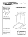
The following guidelines will help you to plan your exercise program. Remember--these
are general guidelines only. For more detailed exercise information, obtain a reputable book or consult your physician.
EXERCISE
INTENSITY
Whether your goal is to burn fat or to strengthen your
cardiovascular system, the key to achieving the
desired results is to exercise with the proper intensity.
The proper intensity level can be found by using your
heart rate as a guide. The chart below shows recommended heart rates for fat burning and aerobic exercise.
HEART
RATE TRAINING
AQ. 20
Exercise
If your goal is to strengthen your cardiovascular system, your exercise must be "aerobic." Aerobic exercise
is activity that requires large amounts of oxygen for
prolonged periods of time. This increases the demand
on the heart to pump blood to the muscles, and on the
lungs to oxygenate the blood. For aerobic exercise,
adjust the speed and incline of the treadmill until your
heart rate is near the highest number in your training
zone.
WORKOUT
GUIDELINES
Each workout should include the lollowing three parts:
A Warm-up--Star
each workout with 5 to 10 minutes
of stretching and light exercise. A proper warm-up increases your body temperature, heart rate and circulation in preparation for exercise.
ZONES
30
40
110 :
50
lO5
60
:
g$
70
90
80
To find the proper heart rate for you, first find your age
near the bottom el the chart (ages are rounded oil to
the nearest ten years). Next, find the three numbers
above your age. The three numbers define your "training zone." The lower two numbers are recommended
heart rates for fat burning; the higher number is the
recommended heart rate for aerobic exercise.
Training Zone Exercise_Atter
warming up, increase
the intensity of your exercise until your pulse is in your
training zone for 20 to 60 minutes. (During the first few
weeks of your exercise program, do not keep your
pulse in your training zone for longer than 20 minutes.)
Breathe regularly and deeply as you exercise--never
hold your breath.
A Cool-down--Finish
each workout with 5 to 10 minutes of stretching to cool down. This will increase the
tlexibi_ity of your muscles and will help prevent post-exercise problems.
Exercise
To measure your heart rate during exercise, use the
pulse sensor. If your head rate is too high or too low,
adjust the speed and incline of the treadmill.
Frequency
To maintain or improve your condition, complete three
workouts each week, with at least one day of rest between workouts. Aiter a lew months, you may complete up to five workouts each week if desired.
Fat Burning
To burn fat effectively, you must exercise at a relatively
low intensity level for a sustained period of time.
During the first few minutes of exercise, your body
uses easily accessible carbohydrate calories for en-
The key to success is to make exercise a regular and
enjoyable part of your everyday lile.
22
i
PART LIST--Model
No. 831.299480
ROSA
To locate the parts listed below, refer to the EXPLODED DRAWING attached in the center of this manual.
Key
No.
Qty.
1
2
3
4*
1
.1
4
1
5
6
7
1
2
1
8
9*
10"*
11
12
13
14
15
16
17
18
19
20
21
22
23
24
25
26
27
28
29
30
1
1
1
1
1
2
1
8
4
4
1
1
2
1
1
1
1
1
1
1
1
1
11
31
32
33
34
35
36
37
1
2
2
1
1
3
2
38
39
40
41
42
43
44
45
46
47
48
49
4
4
1
2
1
1
2
2
10
15
1
2
Description
Key
No.
Qty.
Description
Key
No.
Qty.
Motor Belt
Pulley/Flywheel/Fan
Motor Nut
Motor/Pulley/
Flywheel/Fan
Incline Motor Bolt
Incline Motor Spacer
Incline Motor
50
51
52
53
54
55
56
57
1
1
1
4
4
1
1
1
Book Holder
Front Belly Pan
Power Supply
Cable Tie Clamp
Cable Tie
Walking Belt
Rubber Ring
Rear Roller
101
102
103
104"
105
106
107
108
14
1
2
2
1
1
2
2
Stop Bracket
Latch Assembly
Hand Weight Set
Rear Foot Spacer
Frame
Interface Bracket
Incline Motor Pivot Bolt
Incline Motor Nut
Hood Screw
Plastic Stand-off
Hood Bracket (short)
Hood Bracket (long)
Warning Decal
Reed Switch
Reed Switch Clip
Motor/Controller Wire
Control[er
Electronics Bracket
Circuit Breaker
Power Cord
Power Cord Grommet
On/Off Switch
Hood Bracket Screw/
Incline Shield Screw
Incline Leg
Frame Pivot Bolt
Frame Pivot Spacer
Upright Wire Harness
Front Roller Adj. Bolt
Roller Adj. Washer
Motor Tension Nut/
Front Roller Nut
Motor Bolt
Cap Screw
Left Foot Rail Cap
Foot Rail
Front Roller/Pulley
Magnet
Platform Screw (mid)
Isolator
Isolator Screw
Plastic Fastener
Foam Grip (Right)
Belt Guide
58
59
60
61
62
63
64
65
66
67
68
69
70
71
72
73
74
75
76
77
78
79
80
81
82
83
84
1
2
6
1
5
1
1
2
1
1
4
6
1
1
5
1
1
2
16
1
1
4
1
4
1
2
1
109
110
111
112
113
114
115
116
117
118**
119"*
120"
1
1
1
1
1
1
1
1
2
1
1
2
85
86
87
88
89
90
91
92
93
94
95
96
97
98
99
100
2
2
1
1
12
1
1
1
1
1
2
1
4
1
1
1
Belly Pan Spacer
Rear Foot
Rear Foot Screw
Ground Wire
Ground Wire Screw
Belly Pan
Rear Endcap
Rear Roller Adj. Bolt
Motor
Latch Decal
Platform Screw
Electronics Screw
Latch Catch
Walking Platform
8" Cable Tie
Jack
Motor Tension Bolt
Foot Rail Insert
Small Screw
Console
Ground Nut
Long Screw
iFIT.com Wire
Motor Star Washer
Upright
Incline Leg Pivot Bolt
Hand Pulse
Wire Harness
Handrail Extension
Wheel Bolt
Console Base
Motor Tension Washer
1/2" Screw
Key/Clip
Incline Motor Plate
Right Foot Rail Cap
Motor Tension Bushing
Motor Hoed
Front Wheel
Incline Motor Shield
Thick Base Pad
12" Audio Wire
Upright Grommet
Allen Wrench
121
122
123
124
125
126
127
128"*
129"*
130
131
#
#
#
#
#
#
#
#
2
1
1
1
1
2
2
1
1
1
1
1
1
1
1
1
1
1
1
23
Description
Screw
Lock Knob
Extension Leg
Base Endcap
Shock
Choke
Pulse Bar Bolt
Pulse Bar Washer
Pulse Bar
Foam Grip (Left)
Lock Knob Bracket
Spring
Lock Pin Collar
Pin Clip
Lock Pin
Console Base Bottom
Upright Endcap
Chest Pulse Sensor
iFIT.com CD
Extension Leg
Assembly
Static Decal
Shield
Trim Guard
50" Wire Harness
Ground Washer
Base Pad
Hood Screw (Side)
iFIT.com Module
iFIT.com Video
Hood/Choke Bracket
Console Ground Wire
10" White Wire, 2F
8" Blue Wire, 2F
4" Blue Wire, 2F
4" Black Wire, 2F
4" Green Wire, FIRing
8" Green Wire, 2 Ring
4" Red Wire, M/F
User's Manual
# These parts are not illustrated
* Includes all parts shown in the
box
**These parts are optional. For information about the iFIT.com module,
iFIT.com CD's, or iFIT.com videocassettes, call toll-free 1-800-8840620. For information about the
optional hand weight set or chest
pulse sensor, see page 18.
EXPLODED
DRAWING--Model
No. 831.299480
RO800A
37
52
122
30
62
74
15
88
14
i
15
41
35
75
16
1O6
I
32
51
45
9
70
55
100
16
49
i
57
,_
|
46
6
101
60
SAVE THE EXPLODED DRAWING
FOR FUTURE REFERENCE.
65
To identify the parts shown on this exploded drawing, refer to the
PART LIST on page 23 of the USER'S MANUAL.
36
EXPLODED
DRAWING--Model
No. 831.299480
RO8OOA
87
117
46
90
/
50
107
11
108
79
84
\
109
11o
111
85
83
115
91
20
i
i
127
I
'
73
101
83
103
.. _104
101
97
0
105_
.
.-'"'"""
20
120"---
15
103
[_126
_101
97
95
86
01
123
SEARS
The model number and Serial number of your PROFORIvP 835QT
treadmill are listed on a decal attached to the frame. See the front
cover of this manual to find the location of the decal.
Model No. 831.299480
QUESTIONS?
All replacement parts are available for immediate purchase or
special order when you visit your nearest SEARS Service Center.
To request service or to order parts by telephone, call the toll-free
numbers listed at the left.
If you find that:
• you need help assembling
operating the PROFORM
835QT treadmill
or
When requesting help or service, or ordering parts, please be
prepared to provide the following information:
• a part is missing
• The NAME OF THE PRODUCT (PROFORM"
• or you need to schedule repair
service
call our toll-free HELPLINE
1-800-736-6879
Monday-Saturday,
7 am-7 pm
central Time (excluding holidays)
835QT treadmill)
• The MODEL NUMBER OF THE PRODUCT (831.299480)
• The KEY NUMBER AND DESCRIPTION OF THE PART (see the
EXPLODED DRAWING in the center of this manual and the
PART LIST on page 23).
REPLACEMENT
PARTS
if parts become worn and need
to be replaced, call the following
toll-free number
1-800-FON-PART
(1-800-366-7278)
FULL 90 DAY WARRANTY
For 90 days from the date of purchase, if failure occurs due to defect in material or workmanship in this
SEARS TREADMILL EXERCISER, contact the nearest SEARS Service Center throughout the United
States and SEARS will repair or replace the TREADMILL EXERCISER, free of charge.
This warranty does not apply when the TREADMILL
EXERCISER is used commercially or for rental pur-
pOSeS.
This warranty gives you specific legal rights, and you may also have other rights which vary from state
to state.
SEARS, ROEBUCK AND CO., DEPT. 817WA, HOFFMAN ESTATES, IL 60179
Part No. 166432 R0800A
Printed in USA © 2000 Sears, Roebuck and Co.