1
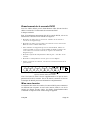
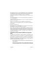
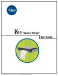
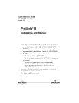
Deutsch
English
Français
Please read this in conjunction with the
Installation Instructions
Cette note doit être lue et jointe aux
instructions d'installation.
Bitte zusammen mit den
Installationsanweisungen lesen.
SECURITE ET COMPATIBILITE
ELECTROMAGNETIQUE
PRODUKTSICHERHEIT UND
ELEKTROMAGNETISCHE VERTRÄGLICHKEIT
(EMV)
PRODUCT SAFETY AND ELECTROMAGNETIC
COMPATIBILITY (EMC)
This product is intended for use in general purpose CCTV
applications in a residential, commercial or light industrial
EMC environment.
Refer to your agent before installing or using the product in
medical and/or intrinsically safe applications or in an
industrial EMC environment.
WARNING : This is a Class A product. In a domestic
environment this product may cause radio interference in
which case the user may be required to take adequate
measures.
The product must be installed in accordance with good
installation practice to enable the product to function as
intended and to prevent problems. Refer to your agent for
installation guidance.
Contact your agent to obtain a specification defining the
acceptable levels of product degradation with regard to EMC
immunity.
MANUFACTURER’S DECLARATION OF
CONFORMANCE
The manufacturer declares that the product supplied with this
document is compliant with the essential protection
requirements of the EMC directive 89/336 and the Low
Voltage Directive LVD 73/23 EEC. Conforming to the
requirements of standards EN 55022 for emissions, IEC801
parts 2, 3 and 4 for immunity and BS415 superseded by
EN60950 for Electrical Equipment safety.
Issue 1
Ce produit est destiné à être utilisé pour les applications
générales de télévision en circuit fermé dans des
environnements résidentiels, commerciaux ou d'industries
légères à compatibilité électromagnétique.
Dieses Produkt ist für den Einsatz in allgemeinen CCTVAnwendungen in Wohn-, Geschäfts- oder leichtindustriellen
Umgebungen ausgelegt.
Prendre conseil auprès du revendeur avant d'installer ou
utiliser le produit pour des applications médicales et/ou à
sécurité intrinsèque ou dans un environnement industriel dans
lesquels des précautions doivent être prises dans le domaine
des interférences radioélectriques.
Wenden Sie sich bitte an Ihre Vertretung, bevor Sie das
Produkt in medizinischen und/oder eigensicheren
Anwendungen oder in einer industriellen EMV-Umgebung
installieren.
ATTENTION : Ce produit est rangé en Classe A. Dans un
environnement domestique il peut provoquer des
interférences radioélectriques. Dans ce cas, l'utilisateur
pourra être amené à prendre des mesures appropriées.
WARNUNG : Dies ist ein Produkt der Klasse A. In einer
Wohnumgebung kann dieses Produkt Funkstörungen
verursachen; in diesem Fall wird der Benutzer
möglicherweise geeignete Maßnahmen ergreifen müssen.
L'installation doit se faire en respectant les règles de l’art afin
de permettre le bon fonctionnement du produit et empêcher
que d’éventuels problèmes surgissent. Pour obtenir des
conseils sur l'installation, s’adresser au revendeur.
Das Produkt muß gemäß guten Installationsverfahren
installiert werden, damit es vorschriftsmäßig funktionieren
kann, und um Probleme zu verhindern. Richtlinien für die
Installation erhalten Sie von Ihrer Vertretung.
Pour obtenir une spécification définissant les niveaux
acceptables de dégradation du produit en relation avec la
compatibilité électromagnétique, s’adresser au revendeur.
Eine Spezifikation, die das akzeptable Ausmaß der
Produktdegradation hinsichtlich EMV-Störfestigkeit festlegt,
können Sie von Ihrer Vertretung anfordern.
DECLARATION DE CONFORMITE PAR LE
FABRICANT
Le fabricant déclare que le produit fourni est conforme aux
prescriptions de la directive 89/336 sur la compatibilité
électromagnétique et de la directive LVD 73/23 sur la basse
tension. Il est également conforme aux normes EN 55022 sur
les émissions, IEC801 sections 2, 3 et 4 sur la compatibilité et
BS415 remplacée par la norme EN60950 relative à la
sécurité des équipements électriques.
HBEMC/LVD -A-1
KONFORMITÄTSERKLÄRUNG DES HERSTELLERS
Der Hersteller erklärt hiermit, daß das mit diesem Handbuch
gelieferte Produkt die grundlegenden Schutzanforderungen
der EMV-Vorschrift 89/336 und der
Niederspannungsverordnung LVD 73/23 EEC erfüllt.
Entspricht den Anforderungen der Normen EN 55022 für
Emissionen, IEC801, Teil 2, 3 und 4, für Störfestigkeit und
BS415, ersetz durch EN60950 für die Sicherheit von
Elektrogeräten.
Issue 1 : 1/97
DVS24
DVS28
Installation and Operating Instructions
English
Dual Monitor Desk Video Switcher
1 – 10
Read these instructions first!
Manuel d’installation et d’utilisation
Français
Console de commutation pour deux écrans
11 – 20
Veuillez lire ces instructions avant de commencer!
Installations- und Betriebsanweisungen
Tisch-Videoumschalter mit zwei Monitoren
Bitte zuerst diese Anweisungen lesen!
Deutsch
21 – 31
BLANK
Page 2
English
For Safety
Please follow these instructions as you install your DVS2 and
have them available during the life-time of the DVS2. If you have
any problems contact your supplier or telephone Baxall’s
Technical Support Department on +44 (0)161 406 6611.
WARNING: INSTALLATION IS ONLY TO BE CARRIED OUT BY
SUITABLY QUALIFIED AND EXPERIENCED
PERSONNEL
WARNING: ONLY USE THE DVS2 WITH THE CLASS 2 POWER
SUPPLY PROVIDED AND DO NOT ATTEMPT TO USE
THE POWER SUPPLY FOR ANY OTHER PURPOSE
The DVS2 is designed for use in general purpose CCTV
applications and must not be used for intrinsically safe or medical
applications.
Do not exceed the voltage and temperature limits given in the
specifications. Only use the DVS2 in a clean, dry, dust-free
environment.
Unpacking
Keep your packaging for use if your DVS2 is stored for a time or
needs to be returned for whatever reason. The packaging should
contain:» The switcher, either:-
the DVS24 with 6 keys,
or the DVS28 with 10 keys.
» A mains-socket mounting +12V DC power supply (class 2)
» These instructions
If any of the items are missing or damaged then inform the
suppliers and carriers immediately, and do not attempt to use
your DVS2.
English
Page 3
The DVS2
Your DVS2 takes either 4 or 8 camera inputs which it switches to
two monitors. You can select cameras by pressing the relevant
numbered key. There is also an AUTO key which starts an
automatic sequence on the current monitor. This sequence displays
all the cameras in numerical order and automatically skips any
unused inputs.
You can sequence both monitors at the same time, with each
displaying its own sequence. The time spent on each camera in a
sequence is called the dwell-time, this can be varied from 1 to 60
seconds. On the main monitor you can change the dwell-time for
each camera separately, however on the spot monitor the same
dwell-time applies to all cameras in the sequence. This is called a
global dwell time.
You can also link the DVS28 to 8 alarm inputs (the DVS24 to 4)
by using it with the AL8. The available response options are
described later in these instructions.
Figure 1. A Typical switcher Arrangement (DVS28)
Page 4
English
Connecting your DVS2
Make all the video connections using 75ohm coaxial cable with
BNC connectors on each end.
When you are ready to connect your DVS2, refer to figure 2 and
follow the instructions given below:» Connect a cable from the connector labelled MAIN to your monitor
or VCR.
» Connect cables from the cameras to the numbered video-input
BNCs.
» Plug the jack-plug from the 12V DC power supply into the
jack-socket marked 12V DC.
» Plug the power supply into a suitable mains power outlet.
» Switch on the cameras, monitor and DVS2 (at the mains power
outlet).
8
7
6
5
4
3
2
1
MAIN
SPOT
ALARM 12V
DC
Earth Terminal
Figure 2. Rear Panel Connections
Note: We have provided a supplementary earth terminal on the
rear panel, please ask Baxall Technical Support if you need
further information.
Switching On the Power
When you switch the power on, your DVS2 may start by
displaying a sequence or a single camera. If it cannot find any
camera inputs then it scans rapidly through the camera selection
LEDs but does not display a picture.
English
Page 5
Operating Your DVS
To select a camera on the MAIN monitor ... simply press a
numbered key.
To select a camera on the SPOT monitor ... press and hold the
SPOT key and press a numbered key.
To start the sequence on the MAIN monitor ... press and release
<AUTO>.
To stop the sequence on the MAIN monitor ... press and release
a numbered key.
To start the sequence on the SPOT monitor ... press and hold
<SPOT> press and release <AUTO>.
To stop the sequence on the SPOT monitor ... press and hold
<SPOT> press and release a numbered key.
To set a dwell-time on the MAIN monitor ... select the camera
you want to change, press and hold <AUTO>. The dwell-time for
the current camera is displayed on the main monitor in seconds.
Use <1> to decrease the dwell-time and <2> to increase it, when
you are satisfied release <AUTO>.
Repeat this for all the cameras you need to change.
To set the global dwell-time on the SPOT monitor ... Press and
hold <SPOT> and <AUTO>. The dwell-time is displayed on the
main monitor in seconds.
Use <1> to decrease and <2> to increase the global dwell-time,
when you are satisfied release <AUTO> then <SPOT>.
NOTE: Switching off the power does not erase any settings.
To position the caption on the screen ... Remove the power plug
from the back of your DVS2. Press and hold <AUTO> and
re-insert the power plug.
Keep <AUTO> held throughout this procedure.
Page 6
English
The caption should now be displaying the model number and
software version.
Use <1> to move the caption up and <2> to move it down.
Press <4> and the display changes to the software date.
Use <1> to move the caption left and <2> to move it right.
Release <AUTO>.
To display the software version ... follow the instructions for
positioning a caption on the screen (above.)
To RESET your DVS2 to factory defaults ... Remove the power
plug from the back of your DVS2. Press and hold <AUTO> and
<SPOT> re-insert the power plug, wait for 3 seconds then release
<AUTO> and <SPOT>.
Using the DVS2 with Alarms
The AL8 has 8 alarm inputs, its function is to tell the DVS2 which
o f the alarms are active. The DVS2 assumes that
alarm 1 = camera 1, alarm 2 = camera 2 and so on. When only
one alarm is active the DVS2 shows the alarmed-camera on the
main monitor. If two or more alarms are active it can either:
• only display the most recent alarmed camera or,
• introduce the alarmed camera into a special sequence with a 2
second dwell-time.
Then, once the alarms are all cleared it can either:
• hold the last alarmed camera on the main monitor,
• start the normal sequence on the main monitor or,
• return to the settings it had before the first alarm.
A flashing LED indicates that the corresponding alarm is active
or has been active. Press the numbered key to cancel this once the
alarm is cleared.
English
Page 7
To Install the AL8
Firstly, follow the instructions supplied with the AL8, then set the
alarm options on your DVS2
To set the alarm options on the DVS2 ... Remove the power plug
from the back of your DVS2. Press and hold <SPOT> and re-insert
the power plug. Press the numbered keys 1 to 3 to toggle the
options on and off (an asterisk represents on). The options are as
follows:Option 1 : start the normal sequence on the main monitor once all
the alarms are cleared.
Option 2 : return the MAIN monitor to its original settings once
all the alarms are cleared.
Option 3 : Sequence the active alarms on the MAIN monitor.
With Options 1 and 2 OFF : your DVS2 holds the last alarmed
camera on the main monitor.
Note: You cannot select both option 1 and option 2 together.
Page 8
English
Specifications
DVS24 : 4 video inputs, 2 video output (6 keys.)
DVS28 : 8 video inputs, 2 video output (10 keys.)
Video Signals
All video 1 V pk-pk composite video via 75ohm coaxial cable with BNC connectors.
Inputs AC coupled, maximum DC offset +/- 2.7 V
Main-Monitor Sequencing Operations
Sequences camera inputs in numerical order skipping unused inputs.
Dwell time is adjustable for each camera between 1 and 60 seconds
Spot-Monitor Sequencing Operations
Sequences camera inputs in numerical order skipping unused inputs.
Dwell time is globally adjustable between 1 and 60 seconds
Alarm Response Functions
Compatible with the Baxall AL8 alarm module the DVS2 has 3 options which apply to
the main monitor:
Option 1: Sequence the main monitor after alarms are cleared
Option 2: Return to previous state after alarms are cleared
Option 3: Sequence the current alarms on the main monitor
If no options are selected it displays the alarmed camera as it receives the alarms.
Power
Power Consumption: Maximum 2.4VA
Voltage range 12V DC +/-10%. Maximum 200mA
Power Supply Units:
230V AC +/-10% to +12V DC +/- 10% (class 2)
Dimensions
DVS24 : 181 x 88 x 36.5mm
DVS28 : 266 x 88 x 36.5mm
Weights
DVS24 : 0.4 kg
DVS28 : 0.6 kg
Material
ABS endcaps with aluminium and mild steel shell
Colour
Graphite-grey, blue lettering and keys
Temperature Specification
Operational temperature limits:-10ºC to +50ºC
at 10% to 80% relative humidity (non-condensing)
Storage temperature limits:-20ºC to +60ºC
at 10% to 95% relative humidity (non-condensing)
English
Page 9
This page is intentionally left blank
Page 10
English
DVS24
DVS28
Installation and Operating Instructions
English
Dual Monitor Desk Video Switcher
1 – 10
Read these instructions first!
Manuel d’installation et d’utilisation
Français
Console de commutation pour deux écrans
11 – 20
Veuillez lire ces instructions avant de commencer!
Installations- und Betriebsanweisungen
Tisch-Videoumschalter mit zwei Monitoren
Bitte zuerst diese Anweisungen lesen!
Deutsch
21 – 31
Baxall Security Limited
Unit 1 Castlehill, Horsfield Way,
Bredbury Park Industrial Estate,
Stockport, Cheshire SK6 2SU
Angleterre.
Tl : +44 (0) 161 406 6611
Fax : +44 (0) 161 406 8828
Baxall Security Limited se réserve le droit de modifier ses produits et leurs
spécifications sans avis préalable.
Edition 2 : 4/95
Page 12
HBDVS2/E
Français
Consignes de sécurité
Lisez ces instructions avant de procéder à l’installation de votre console
de commutation et conservez-les pendant toute la durée de vie de
l’appareil. En cas de problème, contactez votre fournisseur ou le
Service Technique de Baxall au +44 (0) 161 406 6611.
ATTENTION: L’INSTALLATION DOIT ETRE EFFECTUEE
UNIQUEMENT PAR UN TECHNICIEN QUALIFIE ET
EXPERIMENTE.
ATTENTION: LA CONSOLE DE COMMUTATION DOIT ETRE
UTILISEE UNIQUEMENT AVEC LE
TRANSFORMATEUR DE CLASSE 2 FOURNI AVEC
L’APPAREIL. NE PAS UTILISER LE
TRANSFORMATEUR AVEC D’AUTRES APPAREILS.
La console de commutation est conçue pour être utilisée dans les
applications générales de télévision en circuit fermé et ne doit pas être
utilisée pour les applications de sécurité intrinsèque ou médicales.
Ne pas dépasser les limites de tension et de température indiquées dans
les spécifications. La console doit être utilisée uniquement dans un
environnement propre, sec et non poussiéreux.
Emballage
Conserver l’emballage pour entreposer la console dans le cas où elle ne
devrait pas être utilisée pendant un certain temps ou pour la réexpédier
en cas de besoin. L’emballage doit contenir:
» un des modèles de console suivants:
DVS24 à 6 touches
DVS28 à 10 touches.
» un transformateur 12 V cc (classe 2)
» le manuel.
Dans le cas où un de ces articles serait manquant ou endommagé,
informez immédiatement le fournisseur et le transporteur et n’utilisez
pas la console.
Français
Page 13
La console DVS2
La DVS2 permet de raccorder quatre à huit caméras avec deux écrans de
contrôle. Il est possible de sélectionner les caméras en appuyant sur les
touches numérotées correspondantes. La touche AUTO permet de
démarrer une séquence automatique sur l’écran en cours. Cette séquence
permet de passer automatiquement d’une caméra à l’autre par ordre
numérique en sautant les entrées non utilisées.
Il est possible d’exécuter une séquence sur chaque écran simultanément.
Le temps passé sur chaque caméra pendant une séquence est appelé
temps d’arrêt et peut varier de 1 à 60 secondes. Sur l’écran principal
(MAIN), le temps d’arrêt peut être réglé pour chaque caméra séparément
alors que pour l’autre (SPOT) le temps d’arrêt est identique pour toutes
les caméras de la séquence.
Il est également possible de relier la DVS28 à 8 entrées d’alarme (quatre
pour la DVS24) en utilisant le module AL8 (fourni séparément). Les
options de réponse aux alarmes sont décrites un peu plus loin.
Figure 1: Installation caractéristique avec une console DVS2
Page 14
Français
Branchement de la console DVS2
Tous les câbles utilisés pour le branchement vidéo doivent être des
câbles coaxiaux de 75 ohm munis de connecteurs BNC
à chaque extrémité.
Pour le branchement proprement dit de la console DVS2, suivre les
instructions ci-dessous en se référant à la figure 2:
» Brancher un câble entre le connecteur “MAIN” de la console et
l’écran ou le magnétoscope.
» Brancher les câbles en provenance des caméras sur les connecteurs
BNC des entrées vidéos numérotées.
» Pour brancher un magnétoscope sur la console DVS2, utiliser un
connecteur BNC en T sur les sorties MAIN ou SPOT ou utiliser une
sortie vidéo sur l’écran de contrôle (se reporter au manuel du
magnétoscope).
» Brancher la fiche du transformateur dans la prise “12V DC” de la
console.
» Brancher le transformateur sur une prise secteur adaptée.
» Mettre en marche les caméras, l’écran et la console au niveau de la
prise murale.
Figure 2: Panneau arrière de la console
Note: Une borne de mise à la terre supplémentaire a été prévue sur le
panneau arrière de la console. En cas de besoin, contacter le Service
Technique de Baxall pour toute information complémentaire.
Mise sous tension
Au moment de la mise sous tension, la console DVS2 peut commencer
en affichant une séquence ou une seule caméra. Dans le cas où la
console ne détecte aucune entrée, les diodes électroluminescentes
s’allument en séquence mais aucune image n’apparaît.
Français
Page 15
Utilisation de la console DVS
Pour sélectionner une caméra sur l’écran PRINCIPAL, appuyer
simplement sur une touche numérotée.
Pour sélectionner une caméra sur l’écran SPOT, appuyer sur la
touche SPOT et la maintenir enfoncée en appuyant simultanément sur
une touche numérotée.
Pour lancer la séquence sur l’écran PRINCIPAL, appuyer sur la
touche AUTO puis la relâcher.
Pour arrêter la séquence sur l’écran PRINCIPAL, appuyer sur une
touche numérotée puis la relâcher.
Pour lancer la séquence sur l’écran SPOT, appuyer sur la touche
SPOT et la maintenir enfoncée tout en appuyant sur la touche AUTO
avant de la relâcher.
Pour arrêter la séquence sur l’écran SPOT, appuyer sur la touche
SPOT et la maintenir enfoncée tout en appuyant sur une touche
numérotée avant de la relâcher.
Pour régler un temps d’arrêt sur l’écran PRINCIPAL, sélectionner
la caméra concernée, appuyer sur la touche AUTO et la maintenir
enfoncée. Le temps d’arrêt de la caméra en secondes s’affiche sur l’écran
principal.
Utiliser la touche 1 pour diminuer le temps d’arrêt et la touche 2 pour
l’augmenter. Lorsque le temps d’arrêt affiché est correct, relâcher la
touche AUTO.
Répéter cette opération pour chaque caméra dont le temps d’arrêt doit
être modifié.
Pour régler le temps d’arrêt de l’écran SPOT, appuyer sur les touches
SPOT et AUTO et les maintenir enfoncées. Le temps d’arrêt en secondes
s’affiche sur l’écran principal.
Utiliser la touche 1 pour diminuer le temps d’arrêt et la touche 2 pour
l’augmenter. Lorsque le temps d’arrêt affiché est correct, relâcher la
touche AUTO puis la touche SPOT.
NOTE: La mise hors tension de la console n’efface pas les réglages.
Page 16
Français
Pour déplacer le texte sur l’écran, débrancher la fiche d’alimentation
électrique du dos de la console. Appuyer ensuite sur la touche AUTO
et la maintenir enfoncée. Rebrancher la fiche d’alimentation.
Maintenir la touche AUTO enfoncée pendant toute la durée de cette
procédure.
Le texte qui apparaît sur l’écran correspond au numéro de modèle et à
la version du logiciel.
Utiliser la touche 1 pour déplacer le texte vers le haut et la touche 2
pour le faire descendre.
Appuyer sur la touche 4 pour faire apparaître la date du logiciel.
Utiliser la touche 1 pour déplacer le texte vers la gauche et la touche 2
vers la droite.
Relâcher la touche AUTO.
Pour afficher la version du logiciel, suivre les mêmes instructions que
pour déplacer le texte sur l’écran (voir ci-dessus).
Pour revenir aux valeurs par défaut définies en usine, débrancher
la fiche d’alimentation électrique du dos de la console. Appuyer sur les
touches AUTO et SPOT et les maintenir enfoncées tout en rebranchant
la fiche d’alimentation. Attendre 3 secondes avant de relâcher les
touches AUTO et SPOT.
Utilisation de la console DVS2 avec les alarmes
Le module AL8 est muni de 8 entrées d’alarme. Sa fonction est de
signaler les alarmes activées à la console. La console DVS2 présume
que l’alarme 1 correspond à la caméra 1, l’alarme 2 à la caméra 2 et
ainsi de suite. Lorsqu’une seule alarme est activée, la console affiche
la caméra en état d’alarme sur l’écran principal. Lorsque deux ou
plusieurs alarmes sont activées, elle peut:
• soit n’afficher que la caméra la plus récemment mise en
état d’alarme,
• soit introduire la caméra mise en état d’alarme dans une
séquence spéciale avec un temps d’arrêt de 2 secondes.
Français
Page 17
Une fois que toutes les alarmes sont annulées, la console peut:
• soit conserver la dernière caméra en état d’alarme sur
l’écran principal,
• soit lancer la séquence normale sur l’écran principal,
• soit revenir aux réglages de l’écran principal avant la
première alarme.
Une diode électroluminescente clignote pour indiquer que l’alarme
correspondante est ou a été activée. Appuyer sur la touche numérotée
pour éteindre la diode une fois l’alarme annulée.
Installation du module AL8
Tout d’abord, lire les instructions fournies avec le module AL8 puis
définir les options d’alarme sur la console DVS2.
Pour définir les options d’alarme, débrancher la fiche d’alimentation
électrique du dos de la console DVS2. Appuyer sur la touche SPOT et
la maintenir enfoncée tout en rebranchant la fiche d’alimentation.
Appuyer sur les touches 1 à 3 pour sélectionner ou non les options
(l’astérisque correspond à “option sélectionnée”). Les options sont les
suivantes:
Option 1: lancer la séquence normale sur l’écran principal après
annulation de toutes les alarmes.
Option 2: revenir aux réglages de l’écran principal après annulation de
toutes les alarmes.
Option 3: lancer en séquence sur l’écran principal les alarmes activées.
Lorsque les options 1 et 2 ne sont pas sélectionnées, la console DVS2
conserve sur l’écran principal la dernière caméra mise en état d’alarme.
Note: Il est impossible de sélectionner ensemble l’option 1 et l’option 2.
Page 18
Français
Spécifications
DVS24: 4 entrées vidéos, 2 sorties vidéos (6 touches)
DVS28: 8 entrées vidéos, 2 sorties vidéos (10 touches)
Signal vidéo
Signal vidéo composite de 1 V crête à crête via câble coaxial de 75 ohm avec connecteurs BNC.
Entrées à liaison ca, décalage cc + 2,7 V maximum.
Fonctionnement en séquence - écran principal
Passage des caméras par ordre numérique en sautant les entrées non utilisées.
Le temps d’arrêt est réglable pour chaque caméra entre 1 et 60 secondes.
Fonctionnement en séquence - écran SPOT
Passage des caméras par ordre numérique en sautant les entrées non utilisées.
Le temps d’arrêt est réglable entre 1 et 60 secondes pour l’ensemble des caméras.
Réponse aux alarmes
Compatible avec le module d’alarme Baxall AL8, la DVS2 dispose de 3 options applicables à l’écran principal:
Option 1: lancer la séquence normale sur l’écran principal après annulation des alarmes.
Option 2: revenir à l’état initial après annulation des alarmes.
Option 3: lancer en séquence sur l’écran principal les alarmes activées.
Lorsqu’aucune option n’a été sélectionnée, la console affiche la caméra mise en état
d’alarme dès que le signal d’alarme est reçu.
Alimentation
Consommation maximale: 2,4 VA
Tension: 12 V cc + 10 %. 200 mA maximum
Transformateur:
de 230 V ca + 10 % en 12 V cc + 10 % (classe 2)
Dimensions
DVS24: 181 x 88 x 36,5 mm
DVS28: 266 x 88 x 36,5 mm
Poids
DVS24: 400 g
DVS28: 600 g
Matériaux
Bouchons d’extrémité en ABS avec coque en aluminium et acier doux
Couleur
Gris anthracite, touches et caractères bleus.
Plage de températures
Limites de température d’utilisation: - 10C à + 50C
avec une humidité relative de 10 % à 80 % (sans condensation)
Limites de température de stockage: - 20C à + 60C
avec une humidité relative de 10 % à 95 % (sans condensation)
Français
Page 19
Cette page a été laissée en blanc délibérément
Page 20
Français
DVS24
DVS28
Installation and Operating Instructions
English
Dual Monitor Desk Video Switcher
1 – 10
Read these instructions first!
Manuel d’installation et d’utilisation
Français
Console de commutation pour deux écrans
11 – 20
Veuillez lire ces instructions avant de commencer!
Installations- und Betriebsanweisungen
Tisch-Videoumschalter mit zwei Monitoren
Bitte zuerst diese Anweisungen lesen!
Deutsch
21 – 31
Baxall Security Limited
Unit 1 Castlehill, Horsfield Way,
Bredbury Park Industrial Estate,
Stockport, Cheshire SK6 2SU
England
Tel : +44 (0) 161 406 6611
Fax : +44 (0) 161 406 8828
Baxall Security Ltd. behält sich das Recht vor, von Zeit zu Zeit ohne vorherige
Ankündigung an den Kunden Änderungen des Produkts und der Produktspezifikation
vorzunehmen.
Ausgabe 2 : 4/95
Seite 22
HBDVS2/E
Deutsch
Zur Sicherheit
Befolgen Sie diese Anweisungen bitte bei der Installation Ihres DVS2,
und heben Sie sie anschließend solange auf, wie der DVS2
funktionsfähig ist. Wenn Sie irgendwelche Probleme haben, wenden
Sie sich bitte an Ihren Fachhändler oder rufen Sie Baxalls technischen
Service unter der Nummer +44 (0)161 406 6611 an.
WARNUNG: DIE INSTALLATION DARF NUR VON
ENTSPRECHEND QUALIFIZIERTEM UND
ERFAHRENEN PERSONAL AUSGEFÜHRT WERDEN.
WARNUNG: DEN UMSCHALTER NUR MIT DER MITGELIEFERTEN
KLASSE 2 STROMVERSORGUNG BENUTZEN, UND
NICHT VERSUCHEN, DIE STROMVERSORGUNG
FÜR ANDERE ZWECKE ZU BENUTZEN.
Der DVS2 ist für allgemeine CCTV-Anwendungen ausgelegt und darf
nicht für eigensichere oder medizinische Anwendungen benutzt
werden.
Die in den Spezifikationen angegebenen Spannungswerte und
Temperaturgrenzen dürfen nicht überschritten werden. Den DVS2 nur
in sauberen, trockenen und staubfreien Umgebungen benutzen.
Auspacken
Bewahren Sie die Verpackung auf, für den Fall, daß Sie Ihren DVS2
eine zeitlang lagern oder aus irgendeinem Grund zurückschicken
möchten. Die Verpackung sollte folgendes enthalten:
» Den Umschalter den DVS24 mit 6 Eingängen oder
entweder den DVS28 mit 10 Eingängen
» Einen Stromversorgungsstecker + 12V Gleichstromversorgung (Klasse
2)
» Diese Anweisungen
Wenn irgendwelche Posten fehlen oder beschädigt sind, informieren
Sie bitte umgehend den Lieferanten und den Spediteur, und versuchen
Sie nicht, Ihren DVS2 zu benutzen.
Deutsch
Seite 23
Der DVS2
Ihr DVS2 hat entweder 4 oder 8 Kameraeingänge, die er auf zwei
Monitore schaltet. Sie können die Kameras wählen, indem Sie die
entsprechend nummerierte Taste drücken. Außerdem gibt es eine
AUTO-Taste, die automatisch auf den angeschlossenen Monitor
schaltet. Diese Sequenz zeigt alle Kameras in numerischer Reihenfolge
und überspringt automatisch unbelegte Eingänge.
Sie können beide Monitore gleichzeitig auf Sequenz stellen, wobei dann
jeder der beiden Monitore seine eigene Sequenz zeigt. Die Zeit, die bei
jeder Kamera verbracht wird, wird als Verweilzeit (Dwell Time)
bezeichnet, und kann zwischen 1 und 60 Sekunden eingestellt werden.
Am MAIN-Monitor kann man die Verweilzeit für jede einzelne Kamera
separat einstellen, aber am Spot-Monitor gilt die Verweilzeit für alle
Kameras der Sequenz. Dies wird als allgemeine Verweilzeit bezeichnet.
Sie können den DVS28 auch an 8 Alarmeingänge anschließen (den
DVS24 an 4), indem Sie ihn zusammen mit dem AL8 benutzen (separat
lieferbar). Die zur Verfügung stehenden Schaltmöglichkeiten werden
weiter unten in diesen Anweisungen beschrieben.
Abbildung 1. Eine typische Umschalteranordnung (DVS28)
Seite 24
Deutsch
Anschluß Ihres DVS2
Alle Video-Anschlüsse mit 75 Ohm Koaxkabel und BNC-Steckern an
beiden Enden herstellen.
Wenn Sie Ihren DVS2 anschließen möchten, Abbildung 2 betrachten
und die folgenden Anweisungen ausführen:
» Ein Kabel von der mit MAIN gekennzeichneten Steckbuchse an Ihren
Monitor bzw. Ihr VCR anschließen.
» Kabel von den Kameras an die nummerierten
Videoeingang-BNC-Buchsen anschließen.
» Um einen VCR an Ihren DVS2 anzuschließen, wird entweder ein
BNC-T-Stück an den MAIN- oder SPOT-Eingängen benutzt oder ein
Videoausgang an Ihrem Monitor (siehe Gebrauchsanweisungen für
den VCR).
» Den Klinkenstecker von der 12 V Gleichstromversorgung in die mit 12
V DC gekennzeichnete Klinkensteckerbuchse stecken.
» Die Stromversorgung in eine geeignete Netzstromquelle einstecken.
» Kameras, Monitor und DVS2 (am Netz) anschalten.
Abbildung 2. Rückseiten-Anschlüsse
Hinweis: Wir haben zusätzlich einen Umschalter an der Rückseite
bereitgestellt; wenden Sie sich bitte an Baxalls technischen Service,
wenn Sie weitere Information wünschen.
Anschalten des Stroms
Wenn der Strom angeschaltet wird, kann Ihr DVS2 eine Sequenz oder
eine einzelne Kamera zeigen. Wenn er keinen Kameraeingang findet,
wird er schnell die LEDs für die Kamerawahl durchlaufen, ohne jedoch
ein Bild zu zeigen.
Deutsch
Seite 25
Die Benutzung Ihres DVS
Um eine Kamera am MAIN-Monitor (Hauptmonitor) zu wählen...
einfach ein nummerierte Taste drücken.
Um eine Kamera am SPOT-Monitor zu wählen... die SPOT-Taste
drücken und eingedrückt halten, und eine nummerierte Taste drücken.
Um die Sequenz am MAIN-Monitor zu starten... <AUTO> drücken
und wieder loslassen.
Um die Sequenz am MAIN-Monitor anzuhalten... eine nummerierte
Taste drücken und loslassen.
Um die Sequenz am SPOT-Monitor zu starten... <SPOT> drücken
und eingedrückt halten, und <AUTO> drücken und wieder loslassen.
Um die Sequenz am SPOT-Monitor anzuhalten... <SPOT> drücken
und eingedrückt halten, und eine nummerierte Taste drücken und
loslassen.
Um eine Verweilzeit am MAIN-Monitor einzustellen... die Kamera
wählen, deren Wert geändert werden soll, <AUTO> drücken und
eingedrückt halten. Die Verweilzeit für die gegenwärtige Kamera wird
nun auf dem MAIN-Monitor in Sekunden angegeben.
<1> benutzen, um die Verweilzeit zu verkürzen und <2> benutzen, um
sie zu verlängern; wenn Sie den gewünschten Wert erreicht haben,
<Auto>-Taste freigeben.
Dies wird für alle Kameras wiederholt, die geändert werden sollen.
Um die allgemeine Verweilzeit am SPOT-Monitor einzustellen ...
<SPOT> und <AUTO> drücken und eingedrückt halten. Die Verweilzeit
für die gegenwärtige Kamera wird nun auf dem MAIN-Monitor in
Sekunden angegeben.
<1> benutzen, um die allgemeine Verweilzeit zu verkürzen und <2>
benutzen, um sie zu verlängern; wenn Sie den gewünschten Wert erreicht
haben, <Auto>-Taste und dann <SPOT>-Taste freigeben.
HINWEIS: Abschalten des Stroms wird keine der Einstellungen
löschen.
Um die Schriftzeile auf dem Bildschirm zu positionieren... den
Stromstecker hinten vom DVS2 abnehmen. <AUTO> drücken und
eindrückt halten und den Stromstecker wieder einstecken.
Seite 26
Deutsch
Während des ganzen Vorgangs <AUTO> eingedrückt halten.
Die Schriftzeile müßte nun die Modellnummer und Software-Version
zeigen.
<1> benutzen, um die Schriftzeile nach oben zu verschieben, <2>
benutzen, um sie nach unten zu verschieben.
<4> drücken, und die Anzeige wird zum Software-Datum übergehen.
<1> benutzen, um die Schriftzeile nach links zu verschieben, <2>
benutzen, um sie nach rechts zu verschieben.
<AUTO> loslassen.
Um die Software-Version anzuzeigen... Anweisungen für die
Positionierung der Schriftzeile auf dem Bildschirm (oben) befolgen.
RÜCKSTELLEN Ihres DVS2 auf die in der Fabrik eingestellten
Standardwerte... Den Stromstecker hinten an Ihrem DVS2
herausziehen. <AUTO> und <SPOT> drücken und eingedrückt halten,
und den Stromstecker wieder einstecken; 3 Sekunden warten, dann
<AUTO> und <SPOT> loslassen.
Benutzung des DVS mit Alarmvorrichtungen
Der AL8 hat 8 Alarmeingänge; seine Funktion besteht darin, dem
DVS2 zu melden, welche der Alarmvorrichtungen aktiv sind. Der
DVS2 geht davon aus, daß Alarm 1 = Kamera 1, Alarm 2 = Kamera 2
usw. Wenn nur ein Alarm aktiv ist, zeigt der DVS2 die Kamera, deren
Alarm ausgelöst worden ist, auf dem MAIN-Monitor. Wenn zwei oder
mehr Alarmvorrichtungen aktiv sind, kann er entweder:
• nur die Kamera mit dem zuletzt ausgelösten Alarm
zeigen, oder
• die Kamera mit dem ausgelösten Alarm in eine spezielle
Sequenz mit einer Verweilzeit von 2 Sekunden
einbeziehen.
Danach, wenn alle Alarmzustände gelöscht worden sind, kann er
entweder:
• die Kamera mit dem zuletzt ausgelösten Alarm auf dem
MAIN-Monitor schalten,
Deutsch
Seite 27
• wieder mit der normalen Sequenz am MAIN-Monitor
beginnen, oder
• zu der Einstellung zurückkehren, auf die er vor dem
ersten Alarm gestellt war.
Eine blinkende LED-Anzeige bedeutet, daß der entsprechende Alarm
aktiv ist oder aktiv gewesen ist. Die nummerierte Tasten drücken, um
diese Anzeige zu löschen, nachdem der Alarm gelöscht worden ist.
Installation des AL8
Zunächst die mit dem AL8 gelieferten Anweisungen ausführen, dann die
Alarmoptionen an Ihrem DVS2 einstellen.
Um die Alarmoptionen am DVS2 einzustellen... den Stromstecker
hinten am DVS2 herausziehen. <SPOT> drücken und eingedrückt halten
und den Stromstecker wieder anschließen. Die nummerierten Tasten 1
bis 3 benutzen, um die Optionen an- und auszuschalten (ein Sternchen
bedeutet “an”). Die folgenden Optionen stehen zur Verfügung:
Option 1: die normale Sequenz am MAIN-Monitor beginnen, wenn alle
Alarmzustände gelöscht worden sind.
Option 2: MAIN-Monitor kehrt zur ursprünglichen Einstellung zurück,
wenn alle Alarmzustände gelöscht worden sind.
Option 3: Sequenz der aktiven Alarmvorrichtungen auf dem
MAIN-Monitor.
Wenn Option 1 und 2 auf AUS gestellt sind, wird Ihr DVS2 die Kamera
mit dem zuletzt ausgelösten Alarm auf dem MAIN-Monitor halten.
Hinweis: Option 1 und 2 können nicht gleichzeitig gewählt werden.
Seite 28
Deutsch
Spezifikationen
DVS24: 4 Videoeingänge, 2 Videoausgänge (6 Tasten)
DVS28: 8 Videoeingänge, 2 Videoausgänge (10 Tasten)
Videosignale
Alle Videosignale 1V Spitze-Spitze zusammengesetztes Videosignal über 75 Ohm
Koaxkabel mit BNC-Steckern.
Eingänge wechselstrom-gekoppelt, maximale Gleichstrom-Abweichung +/- 2,7V
Sequenzbetrieb des MAIN-Monitors
Bietet Sequenz der Kameraeingänge in numerischer Reihenfolge unter Auslassung
der nicht belegten Eingänge.
Verweilzeit ist für jede Kamera zwischen 5 und 60 Sekunden justierbar.
Sequenzbetrieb des SPOT-Monitors
Bietet Sequenz der Kameraeingänge in numerischer Reihenfolge unter Auslassung
der nicht belegten Eingänge.
Die allgemeine Verweilzeit ist zwischen 5 und 60 Sekunden justierbar.
Alarmreaktion-Funktionen
Der DVS2 ist mit Baxall AL8 Alarmmodul kompatibel und bietet 3 Optionen mit
Auswirkung auf den MAIN-Monitor:
Option 1: Sequenz am MAIN-Monitor, nachdem Alarmzustände gelöscht sind.
Option 2: Zum vorherigen Zustand zurückkehren, nachdem Alarmzustände gelöscht
sind.
Option 3: Sequenz der gegenwärtigen Alarmzustände am MAIN-Monitor.
Wenn keine Option gewählt wird, wird jeweils bei Empfang des Alarms die Kamera
gezeigt, deren Alarm ausgelöst worden ist.
Strom
Stromverbrauch: Maximum 2,4VA
Spannungsbereich 12V Gleichstrom +/- 10%. Maximum 200mA
Benötigte Stromversorgung:
230V Wechselstrom +/- 10% +12V Gleichstromversorgung +/- 10% (Klasse 2)
Abmessungen
DVS24: 181x88x36,5mm
DVS28: 266x88x36,5mm
Gewicht
DVS24: 0,4kg
DVS28: 0,6kg
Material
ABS-Endkappen mit Aluminium- und Weichstahlgehäuse
Farbe
Graphit-grau, blaue Beschriftung und Tasten
Temperaturspezifikation
Betriebstemperaturgrenzen:
-10°C bis +50°C
bei 10% bis 80% relativer Feuchtigkeit (nicht kondensierend)
Lagertemperaturgrenzen:
-20°C bis +60°C
bei 10% bis 95% relativer Feuchtigkeit (nicht kondensierend)
Deutsch
Seite 29
Diese Seite ist absichtlich leer gelassen worden
Seite 30
Deutsch
Diese Seite ist absichtlich leer gelassen worden
Deutsch
Seite 31
Baxall Security Limited
Unit 1 Castlehill, Horsfield Way,
Bredbury Park Industrial Estate,
Stockport, Cheshire. SK6 2SU
England.
Tel: +44(0)161 406 6611
FAX:+44(0)161 406 8828
Baxall Security Ltd. Reserve the right to make changes to the product and specification
of the product from time to time without prior notice to the customer.
Issue 2 : 4/95
HBDVS2/E