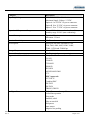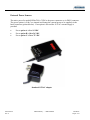
1
Industrial Grade Modems
Hidex HXIIxxTy
User’s Guide
0049-3400-XXX
Rev. C
Hidex HXIIxxTy – USER’S GUIDE
08/18/2010
Raymar Information Technology, Inc.
7325 Roseville Road
Sacramento, CA 95842
800-695-1951
Fax: 916-783-1952
0049-3400-XXX
Rev. C
HIDEX HXIIxxTy – USER’S GUIDE
08/18/2010
Page i
The products and programs described in this User’s Guide are licensed products
of Raymar-Telenetics. This User’s Guide contains proprietary information
protected by copyright, and this User’s Guide and all accompanying hardware
and documentation are copyrighted.
Raymar-Telenetics does not warrant that the hardware will work properly in all
environments and applications, and makes no warranty and representation,
either implied or expressed, with respect to the quality, performance,
merchantability, or fitness for a particular purpose.
Information in this User’s Guide is subject to change without notice and does not
represent a commitment on the part of Raymar-Telenetics. Raymar-Telenetics
assumes no responsibility for any inaccuracies that may be contained in this
User’s Guide.
Raymar-Telenetics makes no commitment to update or keep current the
information in this User’s Guide, and reserves the right to make changes to this
User’s Guide and/or product without notice.
No part of this manual may be reproduced or transmitted in any form or by any
means, electronic or mechanical, including photocopying, recording, or
information storage and retrieval systems, for any purpose other than the
purchaser's personal use, without the express written permission of RaymarTelenetics.
© Copyright 2010 Raymar Information Technology, Inc.
7325 Roseville Road
Sacramento, California 95842
Tel: 800-695-1951 Direct: 916-783-1951
Fax: 916-783-1952
Web site: www.raymarinc.com
0049-3400-xxx
Rev. C
HIDEX HXIIxxTy – USER’S GUIDE
08/18/2010
Page ii
TABLE of CONTENTS
1. DESCRIPTION...............................................………………….Page 1
2. PRODUCT SPECIFICATIONS .....................……………….…Page 1
3. COMPLIANCE TO GLOBAL TELEPHONE STANDARDS....Page 3
4. EXTERNAL POWER SOURCES..................……………….…Page 4
5. POWER CONNECTIONS .............................……………….…Page 5
6. SAFETY GROUND CONNECTION ………………………….Page 6
7. LED INDICATORS ……..…………………………………..…Page 16
8. HARDWARE SETUP..……………………………………........Page 7
9. DIAL LINE SETUP …………..…………………………..…... Page 8
10. LEASED LINE SETUP ……..…………...……………….…. Page 9
11. AT COMMAND SUMMARY ………...…………………..…..Page 10
12. LIMITED WARRANTY ……………………………….….….Page 13
13. RMA PROCEDURE …………………………………………...Page 14
0049-3400-xxx
Rev. C
HIDEX HXIIxxTy – USER’S GUIDE
08/18/2010
Page iii
Description
The Hidex HXII Industrial Grade Modem is the most versatile model for dial-up or leased analog
telephone line interconnects. The Hidex HXII56TM offers speeds up to 56Kbps over the analog
switched telephone network and the HXII33TM is 33Kbps. They are temperature tested, rugged
modems in a metal case designed for Industrial applications. Directly connected to RTUs, traffic
controllers, variable message signs or any number of other applications, they communicate at 300
bps to 56 kbps over analog telephone lines. All HX models have High voltage surge protection on
the telephone lines. The power required is 5VDC. A range of DC power models are optional.
Standard 115VAC adapter is provided.
Product Specifications
Category
Client-to-Server Data Rates
AGC Dynamic Range
Client-to-Client Data Rates
Command Buffer
DAA Isolation
Data Compatibility
Data Compression
Data Format
Diagnostics
Dimensions
Error Correction
Flow Control
Interface
0049-3400-xxx
Rev. C
Description
HXII56TM is V.92 and the HXII33TM is
V.34 data rates
43 dB
56,000; 33,600; 31,200; 28,800; 26,400; 24,000;
21,600; 19,200; 16,800; 14,400; 12,000; 9600;
7200; 4800; 2400; 1200; 0-300 bps
60 characters
1.5Kv r.m.s. or 2121 VDC at 250 VAC
2Kv r.m.s. or 2828 VDC at 125 VAC
(V.92), V.34 enhanced, V.34, V.32 bis,
V.32, V.22bis, V.22; Bell 212A and
103/113, V.21 & V.23
V.42bis, MNP 5
Serial, binary, asynchronous
Local analog loop, local digital loop,
remote digital loop
5.12 x 3.50 x 1.0 inches
V.44, V.42 (LAP-M or MNP 2-4)
XON/XOFF (software), RTS/CTS (hardware)
RS232C via DB25F
HIDEX HXIIxxTy – USER’S GUIDE
08/18/2010
Page 1 of 15
Category
Operating Voltage
Operational Temperature Range
Power Consumption
Receiver Sensitivity
Serial Speeds
Storage Temperature
Transmit Level
Approvals – Modem Module
Intelligent Features
0049-3400-xxx
Rev. C
Description
HXIIxxTM 5 VDC ± 5% Absolute
Maximum Supply Voltage: 5.5 VDC
Option A 9 to 18 VDC via power connector.
Option B 18 to 36 VDC via power connector.
Option C 36 to 72 VDC via power connector.
-40 to +85º C ambient under closed conditions;
humidity range 20-90% (non-condensing)
Typical: 125 mA
Maximum: 138 mA
-43 dBm under worst-case conditions
Serial port data rates adjustable to 300,
1200, 2400, 4800, 9600, 19200, 38400,
57600, 115200 and 230400 bps
-40 to +85ºC
-11 dBm (varies by country setting)
Safety Certifications:
UL1950
UL60950
CUL60950
EN60950
IEC60950
AS/NZS 60950:2000
CCC
EMC Approvals:
FCC Part 15
Canadian EMC
EN 55022
EN 55024
GB4943, GB9254
Fully AT command compatible
Leased-line operation
Sleep mode
Autodial, redial
Pulse or tone dial
Dial pauses
Auto answer
Adaptive line probing
HIDEX HXIIxxTy – USER’S GUIDE
08/18/2010
Page 2 of 15
Automatic symbol and carrier frequency during
start-up, retrain, and rate renegotiations
DTMF detection
Callback security
Distinctive ring
Voice record and playback
Call status display, auto-parity and data rate
selections
Keyboard-controlled modem options
On-screen displays for modem option parameters
Remote configuration
DTR dialing
Phone number storage
Flash memory for firmware updates
NVRAM storage for user-defined parameters
Compliance to Global Telephone Standards
Hidex II modems have passed the following homologation:
FCC Part 68
FCC Part 15
IC-CS03
ETSO TS 103 021-1,2,3 v.1.1.2 2003-09 (originally CTR21)
ESD
- See complete HXIIxxTM AT commands for setting country codes.
0049-3400-xxx
Rev. C
HIDEX HXIIxxTy – USER’S GUIDE
08/18/2010
Page 3 of 15
External Power Sources
The native power for model HXIIxxTM is 5VDC to the power connector or via DB25 connector.
The power options A, B & C are internal and change the external power to be supplied via the
barrel connector (pictured below). If no option is selected the 115VAC external supply is
provided.
•
•
•
Power option A is 9 to 18 VDC.
Power option B is 18 to 36 VDC.
Power option C is 36 to 72 VDC.
Standard 115VAC adapter
0049-3400-xxx
Rev. C
HIDEX HXIIxxTy – USER’S GUIDE
08/18/2010
Page 4 of 15
Power Connections
There are two optional methods of supplying power to the modem. Use the power connector or
via the RS232 cable. A slide switch on the side of the case selects which is used.
Included with each modem is the mating connector for the input power. Connect the external 5
VDC power source to the supplied connector with attention to the +/- polarity of the voltage
source. CAUTION: NOTE THE POLARITY ON THE CONNECTOR LABEL.
There is a power input select switch on the side of the modem nearest the power connector. The
switch is flush or recessed and to select the power connector input, slide the switch away from
the rear panel.
+5V Power Input
Select Switch
Pin 10 plus 5VDC and pin 7 ground
Alternate power can be connected via the DB25 connector pin # 10 for +5VDC and pin # 1 or 7
for ground. To enable this option, move the switch toward the power connector.
0049-3400-xxx
Rev. C
HIDEX HXIIxxTy – USER’S GUIDE
08/18/2010
Page 5 of 15
Safety Ground Connection
+5V Power Input
Select Switch
Ground Jumper Option
Ground screw
Jumper
Use the GREEN case cover screw to connect a
safety ground wire if desired
Data Interface
Data is interfaced via a DB25 female
connector.
Pin 1 GRD
Pin 2 TXD
Pin 3 RXD
Pin 4 RTS
Pin 5 CTS
Pin 6 DSR
Pin 7 SG
Pin 8 DCD
Pin 10
Pin 20 DTR
Pin 22 RI
Signal Ground
Transmit Data
Receive Data
Request to Send
Clear to Send
Data Set Ready
Signal Ground
Carrier Detect
(Alternate power input +5VDC)
use switch
Data Terminal Ready
Ring Indicate
To change the ground jumper position, remove
the two outer enclosure screws and then remove
the cover. The jumper is located in the bottom
left corner, below the LCDs.
Position 1 & 2
Chassis Ground isolated from
Signal Ground.
Position 2 & 3
Common Chassis & Signal
Ground. (factory set)
LED Indicators
DCD Data Carrier Detect
RTS Request To Send
CTS Clear To Send
TXD Transmit Data
RXD Receive Data
RI
Ring Indicate
PWR Power indicator (green)
0049-3400-xxx
Rev. C
HIDEX HXIIxxTy – USER’S GUIDE
08/18/2010
Page 6 of 15
Hardware Setup
Setup Procedure:
1.
2.
3.
Use an RS-232 cable to connect the DB25 connector (J1) on the modem to a PC serial
Port (Typically COM1).
Connect the RJ11 connector to a phone line.
Connect external power +5VDC to the power jack or via alternate DB25 pins 10 & 7.
See the Power Connections section to ensure correct connector polarity and power select
switch position.
Hyper Terminal Setup
The modem can be tested as a standard serial data modem by connecting it to a personal
computer or other data terminal equipment (DTE). Any standard terminal program such as
HyperTerminal or ProComm running on a PC will communicate with the modem.
AT Commands
AT refers to the command prefix (attention sequence) that precedes each command to the
modem. With the exception of A/ all commands must be preceded by AT and end with a carriage
return <return>. Some useful AT commands commonly used are:
The A/ command instructs the modem to repeat the last command line. A command line
termination character is not required for the execution of this command (that is, the command is
executed as soon as the slash is typed).
0049-3400-xxx
Rev. C
HIDEX HXIIxxTy – USER’S GUIDE
08/18/2010
Page 7 of 15
Dial Line Setup
To communicate using the modem, use an asynchronous communication program. The command
set for the modems is compatible with the Hayes command set.
The modem is controlled and configured by the AT (attention command). Each command
consists of the following elements (with the exception of the A/and the +++ command that will
be discussed later). A command is not entered until a carriage return <ENTER> is entered.
Spaces entered are ignored. For example, to enter the command `Answer', type ATA and
<ENTER>.
Some commands do not have parameters. Any missing parameters in a command is assigned the
value zero, which may be a valid parameter for the command. The sequence followed by AT
command causes the modem to enter a command state. That is, AT without a command serves as
a wake up code and an "OK" appears on the screen. The modem queues the commands in a 40character command line. The command line begins with AT and can have several commands. A
separator is not required between the commands.
When a carriage return is received, the commands are performed in the order in which they are
sent to the modem. If more than 40 characters are sent to the modem, an error occurs and all
commands must be re-entered.
A common configuration for a remote modem is to answer the call and hang up on loss of
carrier. To do this the RS232 interface has to be set for the correct configuration.
Option if the Computer uses pins 2, 3, & 7 only - Set the AT commands as follows:
ATS0=1 (modem will answer on the first ring)
AT&D0 (modem will ignore DTR) factory default is AT&D1 which allows the modem to
answer only if DTR is high.
AT&V
To check the state of the "S" registers use AT&V
AT&W0 Don't forget to burn the new codes into E-PROM by AT&W0
To see your typing you made need to turn on E1 for the modem to echo back responses. Some
software doe not like it's data echoed back so don't forget to check E1/E0 if your software is
acting strange.
Note: You may want to put the modem into a quiet mode - ATQ1 (ATQ0 is the default) modem
does not send result codes which can confuse the computer.
A good configuration for a dumb mode operation is:
0049-3400-xxx
Rev. C
AT&F&C1&D0E0Q1S0=1&W0
HIDEX HXIIxxTy – USER’S GUIDE
08/18/2010
Page 8 of 15
Leased Line Modem Setup for HXII56TM
First, always set the terminal data speed to something below the modems transmit speed i.e.
Terminal speed set to 9600 bps and modems connect at 32 Kbps. This is to prevent the modems
buffers from over running.
Next, set the following AT commands and store into NVRAM. Here is an example of Originate
and Answer settings.
ATQ0%C0E0\N1&D0&K0&L1&W. This is the string for the Originate modem (the one that
supplies constant carrier.)
ATQ0%C0E0\N1&D0&K0&L2&W. This is the string for the Answer modem. (the one that
handshakes with the carrier.)
The only difference is the command &L1 or &L2. L1 is originate L2 is answer.
The breakdown of the commands are all prefaced with the AT command:
Q0
= disable result codes
%C0 = disable data compression
E0
= disable command echo
\N1
= direct mode (no error correction)
&D0 = DTR control – ignores true status of DTR and responds as if it is always on.
&K0 = Disable flow control
&L1 = Leased line Originate mode.(&L2 is Answer mode setting)
&W
= Stores settings to NVRAM
These settings will auto connect in about 60 seconds after a power failure on either modem or a
telephone line disconnect/reconnect cycle.
If you connect both modems to the proper terminal and remote panels and they don’t connect the
first time, remove the RS232 cables and jumper pins 4, 6 & 20 together. Connect only the three
leads, 2, 3 & 7 to the modem or terminal connectors.
Even though we have disabled the DTR control and Flow control the modems still want to see
DTR, DSR and RTS connections. That is the reason for the jumpers being installed.
0049-3400-xxx
Rev. C
HIDEX HXIIxxTy – USER’S GUIDE
08/18/2010
Page 9 of 15
AT Command Summary
Organization of AT Commands on the following pages: 1st, by the initial command character
(&, +, %) 2nd, alphabetized by the second command character (Except for listing of AT).
Command
Description
AT
Attention Code
A
Answer
A/
Repeat Last Command
Bn
Communication Standard Setting
Ds
Dial
DS=y
Dial Stored Telephone Number
En
Echo Command Mode Characters
Fn
Echo Online Data Characters
Hn
Hook Control
In
Information Request
Mn
Monitor Speaker Mode
Nn
Modulation Handshake
On
Return Online to Data Mode
P
Pulse Dialing
Qn
Result Codes
Sr=n
Set Register Value
Sr?
Read Register Value
T
Tone Dialing
Vn
Result Code Format
Wn
Result Code Selection
Xn
Result Code Selection
Zn
Modem Reset
&Cn
Data Carrier Detect (DCD) Control
&Dn
Data Terminal Ready (DTR) Control
&En
XON/XOFF Pass-Through
&Fn
Load Factory Settings
0049-3400-xxx
Rev. C
HIDEX HXIIxxTy – USER’S GUIDE
08/18/2010
Page 10 of 15
Command
Description
&Gn
V.22bis Guard Tone Control
&Kn
Flow Control Selection
&Ln
Leased Line Operation (HXII56TM only)
&Pn
Pulse Dial Make-to-Break Ratio Selection
&Qn
Asynchronous Communications Mode
&Sn
Data Set Ready (DSR) Control
&Tn
Loopback Test (V.54 Test) Commands
&V
Display Current Settings
&Wn
Store Current Configuration
&Zy=x
Store Dialing Command
\An
Select Maximum MNP Block Size
\Bn
Transmit Break
\Kn
Break Control
\Nn
Error Correction Mode Selection
\Qn
Flow Control Selection
\Tn
Inactivity Timer
\Vn
Protocol Result Code
-Cn
Data Calling Tone
%A
Adaptive Answer Result Code Enable
%B
View Numbers in Blacklist
%Cn
Data Compression Control
%DCn
AT Command Control
%En
Fallback and Fall Forward Control
%Hn
Direct Connect Enable
%Rn
Cisco Configuration
$EBn
Asynchronous Word Length
$Dn
DTR Dialing
$MBn
Online BPS Speed
$SBn
Serial Port Baud Rate
#CBAn
Callback Attempts
0049-3400-xxx
Rev. C
HIDEX HXIIxxTy – USER’S GUIDE
08/18/2010
Page 11 of 15
Command
Description
#CBDn
Callback delay
# CBF?
Callback Failed Attempts Display
# CBFR
Callback Failed Attempts Reset
# CBIn
Local Callback Inactivity Timer
# CBNy=n
Store Callback Password
# CBPn
Callback Parity
# CBRy
Callback Security Reset
# CBSn
Callback Enable/Disable
#Pn
Set 11-bit Parity
#Sx
Enter Setup Password
#S=x
Store Setup Password
+VDR=x, y I
Distinctive Ring Report
+++AT<CR>
Escape Sequence
%%%ATMTSMODEM<CR>
Remote Configuration Escape Sequence
Complete AT Commands and Programming
The complete AT commands can be downloaded from our web site.
www.raymarinc.com
Raymar Information Technology, Inc.
Phone: (800) 783-1951, +1-916-783-1951
Fax: 916-783-1952
Email: [email protected]
Web: www.raymarinc.com
0049-3400-xxx
Rev. C
HIDEX HXIIxxTy – USER’S GUIDE
08/18/2010
Page 12 of 15
Raymar Information Technology, Inc.
Limited Warranty
One Year Limited Hardware Warranty
Raymar Information Technology, Inc., dba Raymar-Telenetics, warrants their products against defects in hardware, material and workmanship under normal use for one
(1) year from the date of purchase. Raymar will, at no charge, either repair the product (with new or reconditioned parts), or replace it (with a new or reconditioned
product). Repaired replacement products are warranted for either 90 days or the remainder of the original warranty period, whichever is longer. This warranty extends to
the original end-user only.
What This Warranty Does Not Cover
This warranty does not cover: (a) software; (b) installation or service of the product; (c) conditions resulting from consumer damage such as improper maintenance or
misuse, abuse, accident or alteration; (d) all plastic surfaces (including display screens) and all other exposed parts that are scratched or damaged due to normal use; (e)
operation of our products with equipment not supplied by Raymar (f) products which have had the serial number removed or made illegible; or (g) products rented to
others. This warranty applies only to hardware products manufactured by or for Raymar Information Technology, Inc. and identified by the Raymar-Telenetics
trademark, trade name or product identification logo affixed to them. Refer to the Service and Support section of the User’s Guide for service after the warranty expires.
No warranty is made as to coverage availability or grade of service provided by the carrier.
General Provisions
This warranty sets forth Raymar’s entire hardware responsibilities regarding this product. Repair, replacement or refund of the purchase price is at Raymar’s discretion.
THIS WARRANTY IS GIVEN IN LIEU OF ALL OTHER EXPRESS WARRANTIES, IMPLIED WARRANTIES, INCLUDING WITHOUT LIMITATION
IMPLIED WARRANTIES OF MERCHANTABILITY AND FITNESS FOR A PARTICULAR PURPOSE, AND ARE LIMITED TO THE DURATION OF THIS
LIMITED WARRANTY. IN NO EVENT SHALL RAYMAR BE LIABLE FOR DAMAGES IN EXCESS OF THE PURCHASE PRICE OF THE PRODUCT, FOR
ANY LOSS OF USE, LOSS OF TIME, INCONVENIENCE, COMMERCIAL LOSS, LOST PROFITS OR SAVINGS, OR OTHER INCIDENTAL, SPECIAL OR
CONSEQUENTIAL DAMAGES ARISING OUT OF THE USE OR INABILITY TO USE THIS RAYMAR PRODUCT, TO THE FULL EXTENT SUCH MAY BE
DISCLAIMED BY LAW. WITHOUT LIMITING THE FOREGOING, RAYMAR SHALL HAVE NO LIABILITY FOR ANY DATA STORED IN OR USED WITH
THE PRODUCT, INCLUDING THE RECOVERY COSTS OF SUCH DATA OR PROGRAMS.
State Law Rights
SOME STATES DO NOT ALLOW THE EXCLUSION OR LIMITATION OF INCIDENTAL OR CONSEQUENTIAL DAMAGES OR LIMITATIONS ON HOW
LONG AN IMPLIED WARRANTY LASTS. THE ABOVE LIMITATIONS OR EXCLUSIONS MAY NOT APPLY TO YOU. This warranty gives you specific legal
rights, and you may also have other rights which vary from State to State.
Provincial Law Rights
SOME PROVINCIAL LAWS DO NOT ALLOW THE EXCLUSION OR LIMITATION OF IMPLIED WARRANTIES, THE
EXCLUSION OR LIMITATION OF WARRANTY COVERAGE IN CERTAIN SITUATIONS. SOME OF THE ABOVE
LIMITATIONS OR EXCLUSIONS CONTAINED IN THIS LIMITED WARRANTY MAY NOT APPLY TO YOU. This warranty gives you specific rights, and you
may have other rights which vary from province to province.
How To Use Raymar’s Limited Warranty Service
To take advantage of this warranty, you must do the following:
• If you are having trouble with your product, contact Raymar service using the appropriate number from the Service and Support
section of the User’s Guide. If it is determined that your product requires service, you will be issued a Return Materials
Authorization (RMA) form.
• Pack the defective product securely for shipping. Include only the units pre-approved by service on your RMA form.
• This warranty is void if the product is damaged in transit, you must insure your shipment.
• Ship the defective product, proof of date of purchase, and the RMA form to the address specified.
• Display your RMA number prominently on the outside of the shipping box. Customer is responsible for freight in, door to door. Raymar is responsible for return
shipping costs.
• To ensure prompt service, please write on the RMA form a brief description of the problem you are experiencing with the
product.
Raymar Information Technology, Inc.
7325 Roseville Road
Sacramento, CA 95842
Service Hotline (800) 747-1522
http://support.telenetics.com or e-mail to [email protected]
0049-3400-xxx
Rev. C
HIDEX HXIIxxTy – USER’S GUIDE
08/18/2010
Page 13 of 15
Raymar Information Technology, Inc.
Return Merchandise Authorization (RMA) Procedure
Before returning any Raymar-Telenetics product, an RMA number must be obtained.
The most convenient way to obtain an RMA number for a product purchased from Raymar-Telenetics is to call
1-800-747-1522. When doing so, please have the following information ready:
-
Company name
Full billing address, as well as the address for the location where the product should be returned once
repaired or replaced
Telephone & Fax numbers
Email address
Product model number and serial number
For each item being returned, please include the product model number, the serial number, a description of the
problem being encountered, and the cause of the problem (if known).
Please note that prior to authorizing a return, a product support specialist may call to verify that the product is
properly installed or may ask you to perform tests to insure that the product has actually failed.
The product must be properly packed and returned to:
Raymar-Telenetics
7325 Roseville Road
Sacramento, CA 95842
The RMA number must be legibly displayed on the shipping carton. Raymar-Telenetics will not be responsible
for any product returned without an RMA number.
If the product is out of warranty, estimates for repair rates and any applicable shipping costs will be
communicated by a customer service representative. Currently, Raymar-Telenetics accepts purchase orders or
credit cards as payment methods.
Repairs currently require 5 – 10 business days and are returned via UPS Ground.
0049-3400-xxx
Rev. C
HIDEX HXIIxxTy – USER’S GUIDE
08/18/2010
Page 14 of 15
0049-3400-xxx
Rev. C
HIDEX HXIIxxTy – USER’S GUIDE
08/18/2010
Page 15 of 15