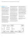
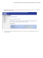
1
Intel® Cloud Builders Guide
Intel® Xeon® Processor-based Servers
Data Center Energy Management with Dell, Intel, and ZZNode
Intel® Cloud Builders Guide to Cloud Design
and Deployment on Intel® Platforms
Data Center Energy Management with Dell, Intel, and ZZNode
Audience and Purpose
Intel® Xeon® Processor 5500 Series
Intel® Xeon® Processor 5600 Series
September 2011
This reference architecture outlines the usage of energy management technologies as
part of planning, provisioning and optimizing strategies in cloud data centers to reduce
energy cost and to address carbon emissions for green IT goals. It is intended for data
center administrators and enterprise IT professionals who seek energy management
solutions to achieve better energy efficiency and power capacity utilization within
new or existing data centers. The techniques and results described can be used as a
reference to understand energy management solutions implemented with the use of
hardware and software components. The reader should be able to develop appropriate
energy management solutions based on the design options presented using ZZNode
Energy Management Solution and Dell* PowerEdge* C-Series Servers implementing
Intel® power management technologies.
Intel® Cloud Builders Guide: Data Center Energy Management with Dell, Intel, and ZZNode
Table of Contents
Executive Summary. . . . . . . . . . . . . . . . . . . . . . . . . . . . . . . . . . . . . . . . . . . . . . . . . . . . . . . . . . . . . . . . . . . . . . . . . . . . . . . . . . . . . . . . . . . . . . . . 4
Introduction . . . . . . . . . . . . . . . . . . . . . . . . . . . . . . . . . . . . . . . . . . . . . . . . . . . . . . . . . . . . . . . . . . . . . . . . . . . . . . . . . . . . . . . . . . . . . . . . . . . . . . . 4
Server Power Management . . . . . . . . . . . . . . . . . . . . . . . . . . . . . . . . . . . . . . . . . . . . . . . . . . . . . . . . . . . . . . . . . . . . . . . . . . . . . . . . . . . . . . . . 5
EDCM (E2E-ALOES Lite) Energy Management Solutions . . . . . . . . . . . . . . . . . . . . . . . . . . . . . . . . . . . . . . . . . . . . . . . . . . . . . . . . . . . . . . 6
Dell PowerEdge C-Series Servers . . . . . . . . . . . . . . . . . . . . . . . . . . . . . . . . . . . . . . . . . . . . . . . . . . . . . . . . . . . . . . . . . . . . . . . . . . . . . . . . . . . 6
Test Bed Blueprint . . . . . . . . . . . . . . . . . . . . . . . . . . . . . . . . . . . . . . . . . . . . . . . . . . . . . . . . . . . . . . . . . . . . . . . . . . . . . . . . . . . . . . . . . . . . . . . . . 6
Design Considerations . . . . . . . . . . . . . . . . . . . . . . . . . . . . . . . . . . . . . . . . . . . . . . . . . . . . . . . . . . . . . . . . . . . . . . . . . . . . . . . . . . . . . . . . . . 6
Software Architecture. . . . . . . . . . . . . . . . . . . . . . . . . . . . . . . . . . . . . . . . . . . . . . . . . . . . . . . . . . . . . . . . . . . . . . . . . . . . . . . . . . . . . . . . . . 7
Hardware and Software Description. . . . . . . . . . . . . . . . . . . . . . . . . . . . . . . . . . . . . . . . . . . . . . . . . . . . . . . . . . . . . . . . . . . . . . . . . . . . . 7
Physical Architecture . . . . . . . . . . . . . . . . . . . . . . . . . . . . . . . . . . . . . . . . . . . . . . . . . . . . . . . . . . . . . . . . . . . . . . . . . . . . . . . . . . . . . . . . . . . 8
Server Setup and Configuration. . . . . . . . . . . . . . . . . . . . . . . . . . . . . . . . . . . . . . . . . . . . . . . . . . . . . . . . . . . . . . . . . . . . . . . . . . . . . . . . . 9
EDCM Energy Management Solution Installation and Configuration. . . . . . . . . . . . . . . . . . . . . . . . . . . . . . . . . . . . . . . . . . . . . . . . 9
Energy Management Use Cases. . . . . . . . . . . . . . . . . . . . . . . . . . . . . . . . . . . . . . . . . . . . . . . . . . . . . . . . . . . . . . . . . . . . . . . . . . . . . . . . . . . . 18
Use Case One: Real Time Server Power Monitoring, Reporting, and Analysis. . . . . . . . . . . . . . . . . . . . . . . . . . . . . . . . . . . . . . 18
Real Time Power Measurement Report . . . . . . . . . . . . . . . . . . . . . . . . . . . . . . . . . . . . . . . . . . . . . . . . . . . . . . . . . . . . . . . . . . . . . . 18
Energy Consumption Distributed Report. . . . . . . . . . . . . . . . . . . . . . . . . . . . . . . . . . . . . . . . . . . . . . . . . . . . . . . . . . . . . . . . . . . . . 19
Events Report. . . . . . . . . . . . . . . . . . . . . . . . . . . . . . . . . . . . . . . . . . . . . . . . . . . . . . . . . . . . . . . . . . . . . . . . . . . . . . . . . . . . . . . . . . . . . . 19
Energy Cost and Carbon Emission Settings. . . . . . . . . . . . . . . . . . . . . . . . . . . . . . . . . . . . . . . . . . . . . . . . . . . . . . . . . . . . . . . . . . 20
Device Level Power Demand Report. . . . . . . . . . . . . . . . . . . . . . . . . . . . . . . . . . . . . . . . . . . . . . . . . . . . . . . . . . . . . . . . . . . . . . . . . 21
Energy Cost Report. . . . . . . . . . . . . . . . . . . . . . . . . . . . . . . . . . . . . . . . . . . . . . . . . . . . . . . . . . . . . . . . . . . . . . . . . . . . . . . . . . . . . . . . 22
Carbon Emission Report. . . . . . . . . . . . . . . . . . . . . . . . . . . . . . . . . . . . . . . . . . . . . . . . . . . . . . . . . . . . . . . . . . . . . . . . . . . . . . . . . . . . 22
Rack Level Energy Reporting. . . . . . . . . . . . . . . . . . . . . . . . . . . . . . . . . . . . . . . . . . . . . . . . . . . . . . . . . . . . . . . . . . . . . . . . . . . . . . . 23
Use Case Two: Power Guard Rail and Optimize Rack Density/Usage. . . . . . . . . . . . . . . . . . . . . . . . . . . . . . . . . . . . . . . . . . . . . . . 24
Rack Level Energy Reporting. . . . . . . . . . . . . . . . . . . . . . . . . . . . . . . . . . . . . . . . . . . . . . . . . . . . . . . . . . . . . . . . . . . . . . . . . . . . . . . . 24
Optimize Rack Density/Usage . . . . . . . . . . . . . . . . . . . . . . . . . . . . . . . . . . . . . . . . . . . . . . . . . . . . . . . . . . . . . . . . . . . . . . . . . . . . . . . 24
Power Guard Rail . . . . . . . . . . . . . . . . . . . . . . . . . . . . . . . . . . . . . . . . . . . . . . . . . . . . . . . . . . . . . . . . . . . . . . . . . . . . . . . . . . . . . . . . . . . 24
Monitor Power Consumption . . . . . . . . . . . . . . . . . . . . . . . . . . . . . . . . . . . . . . . . . . . . . . . . . . . . . . . . . . . . . . . . . . . . . . . . . . . . . . . . 24
Set Power Cap. . . . . . . . . . . . . . . . . . . . . . . . . . . . . . . . . . . . . . . . . . . . . . . . . . . . . . . . . . . . . . . . . . . . . . . . . . . . . . . . . . . . . . . . . . . . . 25
Verify Power Cap. . . . . . . . . . . . . . . . . . . . . . . . . . . . . . . . . . . . . . . . . . . . . . . . . . . . . . . . . . . . . . . . . . . . . . . . . . . . . . . . . . . . . . . . . . 26
Optimize Rack Density . . . . . . . . . . . . . . . . . . . . . . . . . . . . . . . . . . . . . . . . . . . . . . . . . . . . . . . . . . . . . . . . . . . . . . . . . . . . . . . . . . . . . 27
Continue Monitoring the Power Consumption . . . . . . . . . . . . . . . . . . . . . . . . . . . . . . . . . . . . . . . . . . . . . . . . . . . . . . . . . . . . . . . 27
Use Case Three: Disaster Recovery / Business Continuity. . . . . . . . . . . . . . . . . . . . . . . . . . . . . . . . . . . . . . . . . . . . . . . . . . . . . . . 28
Use Case Four: Power Optimized Workloads. . . . . . . . . . . . . . . . . . . . . . . . . . . . . . . . . . . . . . . . . . . . . . . . . . . . . . . . . . . . . . . . . . . . 29
Workload Set up. . . . . . . . . . . . . . . . . . . . . . . . . . . . . . . . . . . . . . . . . . . . . . . . . . . . . . . . . . . . . . . . . . . . . . . . . . . . . . . . . . . . . . . . . . . 29
Steps for Execution. . . . . . . . . . . . . . . . . . . . . . . . . . . . . . . . . . . . . . . . . . . . . . . . . . . . . . . . . . . . . . . . . . . . . . . . . . . . . . . . . . . . . . . . 29
Results. . . . . . . . . . . . . . . . . . . . . . . . . . . . . . . . . . . . . . . . . . . . . . . . . . . . . . . . . . . . . . . . . . . . . . . . . . . . . . . . . . . . . . . . . . . . . . . . . . . . 30
2
Intel® Cloud Builders Guide: Data Center Energy Management with Dell, Intel, and ZZNode
Composite: Policy Based Power Management Use Cases . . . . . . . . . . . . . . . . . . . . . . . . . . . . . . . . . . . . . . . . . . . . . . . . . . . . . . . . . . . . 31
Use Case Five: Data Center Energy Reduction through Power-Aware Support for Multiple Service Classes. . . . . . . . . 31
Purpose. . . . . . . . . . . . . . . . . . . . . . . . . . . . . . . . . . . . . . . . . . . . . . . . . . . . . . . . . . . . . . . . . . . . . . . . . . . . . . . . . . . . . . . . . . . . . . . . . . . . 31
Pre-requisites . . . . . . . . . . . . . . . . . . . . . . . . . . . . . . . . . . . . . . . . . . . . . . . . . . . . . . . . . . . . . . . . . . . . . . . . . . . . . . . . . . . . . . . . . . . . . . 31
Steps for Execution. . . . . . . . . . . . . . . . . . . . . . . . . . . . . . . . . . . . . . . . . . . . . . . . . . . . . . . . . . . . . . . . . . . . . . . . . . . . . . . . . . . . . . . . . 31
Results. . . . . . . . . . . . . . . . . . . . . . . . . . . . . . . . . . . . . . . . . . . . . . . . . . . . . . . . . . . . . . . . . . . . . . . . . . . . . . . . . . . . . . . . . . . . . . . . . . . . . 31
Things to Consider . . . . . . . . . . . . . . . . . . . . . . . . . . . . . . . . . . . . . . . . . . . . . . . . . . . . . . . . . . . . . . . . . . . . . . . . . . . . . . . . . . . . . . . . . . . . . . . 32
Architectural Considerations . . . . . . . . . . . . . . . . . . . . . . . . . . . . . . . . . . . . . . . . . . . . . . . . . . . . . . . . . . . . . . . . . . . . . . . . . . . . . . . . . . 32
Scalability. . . . . . . . . . . . . . . . . . . . . . . . . . . . . . . . . . . . . . . . . . . . . . . . . . . . . . . . . . . . . . . . . . . . . . . . . . . . . . . . . . . . . . . . . . . . . . . . . 32
Power Management. . . . . . . . . . . . . . . . . . . . . . . . . . . . . . . . . . . . . . . . . . . . . . . . . . . . . . . . . . . . . . . . . . . . . . . . . . . . . . . . . . . . . . . . 32
Power Capping Policy in EDCM. . . . . . . . . . . . . . . . . . . . . . . . . . . . . . . . . . . . . . . . . . . . . . . . . . . . . . . . . . . . . . . . . . . . . . . . . . . . . . 32
Glossary. . . . . . . . . . . . . . . . . . . . . . . . . . . . . . . . . . . . . . . . . . . . . . . . . . . . . . . . . . . . . . . . . . . . . . . . . . . . . . . . . . . . . . . . . . . . . . . . . . . . . . . . . 32
References . . . . . . . . . . . . . . . . . . . . . . . . . . . . . . . . . . . . . . . . . . . . . . . . . . . . . . . . . . . . . . . . . . . . . . . . . . . . . . . . . . . . . . . . . . . . . . . . . . . . . . 33
APPENDIX A: Server Power Management. . . . . . . . . . . . . . . . . . . . . . . . . . . . . . . . . . . . . . . . . . . . . . . . . . . . . . . . . . . . . . . . . . . . . . . . . . 34
Intel Power Management Technologies . . . . . . . . . . . . . . . . . . . . . . . . . . . . . . . . . . . . . . . . . . . . . . . . . . . . . . . . . . . . . . . . . . . . . . . . 34
Intel Intelligent Power Node Manager. . . . . . . . . . . . . . . . . . . . . . . . . . . . . . . . . . . . . . . . . . . . . . . . . . . . . . . . . . . . . . . . . . . . . . . . . . 34
APPENDIX B: Dell PowerEdge C-Series Server Configuration for Power Management . . . . . . . . . . . . . . . . . . . . . . . . . . . . . . . 35
3
Intel® Cloud Builders Guide: Data Center Energy Management with Dell, Intel, and ZZNode
Executive Summary
The evolution of cloud computing has
resulted in highly efficient and carefully
optimized data centers with increased
server density and capacity that makes
considerations on energy consumption
and utilization extremely critical along
with several other factors that were
not as significant in smaller data centers
of the past. To support this evolution,
Intel works with end users to create
an open data center roadmap of usage
models that address key IT pain points
for more secure, efficient, and simple
cloud architectures built on a foundation
of transparency. This paper describes
an Energy Management reference
architecture based on Dell, Intel, and
EDCM* (Beijing ZZNode Technologies Co.,
Ltd.) solutions with usage models aimed at
data center power efficiency and optimal
utilization of provisioned power and
cooling capacity.
The goal of energy management usage
models is to optimize productivity per
watt in order to reduce total cost of
ownership (TCO). Requirements include
the capability to monitor and cap power
in real-time at server, rack, zone, and data
center levels. This means the ability to
monitor and manage aggregated power
consumption within a rack, zone, or data
center based on available power and
cooling resources
In this reference architecture we used
Dell PowerEdge C-Series Servers with
Intel® Intelligent Power Node Manager1
(Intel Node Manager) and EDCM Energy
Management Software2 which uses
Intel® Data Center Manager3 (Intel DCM)
to provide data center energy efficiency
through real time power monitoring of the
servers, power capping and policy based
energy management.
We describe the following energy
management use cases in detail along
with experimental results and data.
4
1. Real-time Server Energy Usage
Monitoring, Reporting and Analysis
to get continuous and actual
energy usage visibility via agentless
monitoring of the servers along with
other devices and systems in the
enterprise network, data center and
facilities. The actionable reporting
and analysis with real-time power
monitoring enables reduction in
energy cost and carbon emissions.
2. Power Guard Rail and Optimization
of Rack Density by imposing power
guard to prevent server power
consumption from straying beyond
preset limit. The deterministic power
limit and guaranteed server power
consumption ceiling helps maximize
server count per rack and therefore
return of investment of capital
expenditure per available rack power
when rack is under power budget
with negligible or no per server
performance impact.
3. Disaster Recovery/Business
Continuity by applying significantly
lower power caps to lower power
consumption and heat generation
when unforeseen circumstances
like power outage and cooling
system failure occurs. In these
scenarios it may be appropriate to
set aggressively lower power caps
to though performance would be
affected. The use case illustrates
how it works at a data center location
or a group of servers.
4. Power Optimized Workloads to
achieve power efficiency. Workload
profiles are built and a maximum
performance loss target set.
Experiments determine how much
capping can be applied before
the performance target is hit.
The approach is to match actual
performance against service level
requirements. For workloads that
were not processor intensive, we
were able to optimize server power
consumption by approximately
20 percent without an impact on
performance. For workloads that
were processor intensive, for the
same 20 percent power saving,
we saw an 18 percent decrease in
performance. For a 10 percent power
reduction, performance decreased by
14 percent.
5. Data Center Energy Reduction
through Power Aware Support for
Multiple Service Classes showcases
the ability to enforce multiple SLAs
across different populations of users
with different priority workloads.
Workloads that ran over a period of
eight hours realized 25 percent less
energy consumption.
The paradigm of cloud computing brings
opportunity for data center efficiency.
Energy management usage models
addressed here can substantially help to
meet power management requirements.
EDCM Energy Management Solution
can manage a wide range of devices
and systems in the data center to
reduce energy cost; however this paper
focuses on its usage models on servers,
specifically Dell PowerEdge C-Series
servers with Intel power management
technologies.
Introduction
Cloud computing is the new model for IT
services that has emerged to break the
trend of decline in flexibility combined
with increase in costs. It is an approach
to computing that uses the efficient
pooling of an on-demand, self-managed
infrastructure, consumed as a service.
This approach extrapolates applications
and information from the complexity
of underlying infrastructure, so IT can
support and enable business value. In
concert with Dell, Intel, and other industry
leaders, EDCM helps reduce energy costs
in cloud data centers with its innovative
agentless energy management solutions.
Intel® Cloud Builders Guide: Data Center Energy Management with Dell, Intel, and ZZNode
At the core of cloud computing is the
ability of the underlying compute,
network, and storage infrastructure to act
as an efficient, shared resource pool that
is dynamically scalable within one data
center or across multiple data centers.
With this foundation, critical higher-level
capabilities such as energy management,
guaranteed quality of service, federation,
and data center automation are made
possible. Intel, along with leaders in
software, works to address these new
core innovations in Infrastructure as a
Service (IaaS). Intel has initiated a program
to rapidly enable enterprises and service
providers to clarify best practices around
design (including reference architectures),
deployment, and management. For
enterprise IT and cloud service providers
who need to utilize their existing data
center infrastructure to supply cloud
services to their customers, this guide, as
part of the Intel® Cloud Builders initiative,
provides a comprehensive solution
overview that covers technical planning
and deployment considerations.
While server performance-per-watt
continues to increase, the energy
consumed per server also continues
to rise. These advancements enable
increasing number of servers and
density in modern data centers, making
planning and managing power and
cooling resources critically important to
ensure efficient utilization of provisioned
capacity. In order to realize the vision of
cloud computing, new technologies are
needed to address power efficiency and
energy management. These will become
fundamental to architectures from the
micro-processor stage up through the
application stack. The focus of this paper
is energy management and the related
usage models.
Based on the Environmental Protection
Agency’s report to the government, in
2006 data centers in the US consumed
about 1.5 percent of the nation’s energy
and were poised to double this by 20114
If storage, network, and computing
resources continue to grow at their
predicted rate, new power efficient usage
models will be required. Higher server
utilization, better throughput for network
and storage traffic, as well as storage
optimized by data type and needs, are
a few ways to maximize the existing
resources to achieve efficiency.
Companies continue to explore
approaches that focus on using existing
data center power more efficiently to
increase computing capacity, cut power
costs, and reduce carbon footprint.
Traditionally, organizations have lacked
detailed information about actual server
power consumption in everyday use.
Typically, data center computing capacity
has been based on nameplate power, peak
server power consumption, or derated
power loads. In practice however, actual
power consumption with real data center
workloads is much lower than the ratings.
This situation results in over-provisioned
data center cooling and power capacity,
and increased TCO. Better understanding
and control over server power
consumption allows for more efficient
use of existing data center facilities. All of
this, applied across tens of thousands of
servers, can result in considerable savings.
This paper begins with an overview of
server power management and solutions
offered by Dell and EDCM. We then
describe various usage models in detail
describing the test cases executed and
their results with screenshots of the
configuration and test process. Finally, we
describe architectural considerations to be
taken into account.
Server Power Management
In the past, power consumption used to
be an afterthought for server deployment
in data centers. Unfortunately, this view
persists. For example, in many facilities
the utility bill is bundled with the overall
building charge which reduces the
visibility of the data center cost.
Even though servers have become much
more efficient, packaging densities and
power have increased much faster. As a
result, power and its associated thermal
characteristics have become the dominant
components of operational costs. Power
and thermal challenges in data centers
include:
•Increased total operational costs due to
increased power and cooling demands
•Physical limitations of cooling and
power within individual servers, racks,
and data center facilities
•Lack of visibility into actual real-time
power consumption of servers and
racks
•Complexity of management components
and sub-systems from multiple vendors
with incompatible interfaces and
management applications
These challenges to manage datacenters
can be translated into the following
requirements:
•Power monitoring and capping
capabilities at all levels of the data
center (system, rack identification, and
data center). What can be done at an
individual server level becomes much
more compelling once physical or virtual
servers are scaled up significantly.
•Aggregation of the power consumed
at the rack level and management of
power within a rack group to ensure
that the total power does not exceed
the power allocated to a rack.
•Higher level aggregation and control at
the row or data center level to manage
power budget within the average
power and cooling resources available.
•Optimization of productivity per watt
through management of power at the
server, rack, row, and data center levels
to optimize TCO.
5
Intel® Cloud Builders Guide: Data Center Energy Management with Dell, Intel, and ZZNode
•Application of standards-based power
instrumentation solutions available
in all servers to allow management
for optimal data center efficiency.
Extension of instrumentation to enable
load balancing or load migration based
on power consumption, and close
coupled cooling for the management of
pooled power and cooling resources.
EDCM (E2E-ALOES Lite) Energy
Management Solutions
EDCM is an intelligent software platform
for IDC’s energy conservation that
integrates the DCM function. EDCM can
collect key performance information
from the hardware and analyze the data.
Meanwhile, the energy conservation
strategies can be carried out without
impacting the quality of service.
EDCM is a three layer software
architecture and management console for
power management developed by ZZNode
(http://www.ZZNode.com). The solution
integrates with DCM graphical display and
monitoring capabilities for enterprise data
center environments. It can implement
energy conservation strategies, generate
carbon emission reports, and perform
energy saving reporting and analysis
to influence quality of service (QoS).
Users can access platform and system
via mainstream web browsers and get
rich set data with performance to make
key performance decisions for their data
center environments.
Dell PowerEdge C-Series Servers
Dell has extended its PowerEdge server
family with the new C-Series. Designed
with inspiration from Dell’s DCS business,
these new servers are feature-optimized
and power-optimized for customers in
HPC, Web 2.0, telcos/hosters, big data
and cloud builders. The new PowerEdge C
servers include:
6
•PowerEdge C1100: increased-memory,
power-efficient, cluster-optimized
compute node server (1U/2S, Up to
192GB RAM, Intel® Xeon® processor
5500, 2 x 1GbE Intel® 82576 Gigabit
Ethernet Controller): Great for power
and space sensitive customers requiring
maximum memory flexibility.
•PowerEdge C2100: high performance
dataanalytics, cloud compute platform
and cloud storage server (2U/2S, Up
to 192GB RAM, Intel Xeon processor
5500/5600 series, 2 x 1GbE Intel
82576 Gigabit Ethernet Controller):
Great for scale-out data center
environments where memory and
storage density matter most such as
Hadoop, Map/Reduce, Web analytics,
and database.
•PowerEdge C6100: 4-node cloud and
cluster optimized shared infrastructure
server (2U/Up to 4 2S server
nodes [hot-serviceable], Intel Xeon
processor 5500/5600): Great for
Hyperscale-inspired building block for
high-performance cluster computing
(HPCC), Web 2.0 environments and
cloud builders where the performance
is key.
•PowerEdge C5220 Series Microservers,
from 8 to 12 independent 1-socket
server nodes in a 3U chassis shared
infrastructure server: 1S Intel®
Xeon® E3 platform C204 Chipset:
Great for dedicated hosting, Web 2.0
environments, and cloud builders where
power/density is key.
Test Bed Blueprint
Intel has worked with Dell and EDCM
to implement a test bed that features
Dell’s hyperscale-inspired PowerEdge
C-Series servers, which are designed
specifically for power and space sensitive
data centers. The test bed is intended to
provide a flexible environment to simulate
those aspects of a commercial data center
that are relevant to cloud computing
usage models. EDCM Energy Management
software uses Intel DCM as an integrated
component.
Design Considerations
Intel Node Manager compliant systems
along with PMBus compliant power
supply for real-time power monitoring are
required.
Intel® Cloud Builders Guide: Data Center Energy Management with Dell, Intel, and ZZNode
Software Architecture
The following diagram shows a high level view of EDCM Energy Manager Architecture components.
Figure 1: Software Architecture for EDCM
Hardware and Software Description
EDCM Energy
Management Server
Virtual Machine hosted
on VMware*
4 CPUs, 6 GM RAM, 50GB Hard Disk
Software
Microsoft* Windows* 2008 R2 64 bit, .NET 4.0
Intel DCM 2.1.0.1159 or later
EDCM Energy Management Software
Server1
Dell PowerEdge C1100
2-way Intel® Xeon® Processor E5570 @ 2.93GHz with 12GB RAM, 250GB
SATA HDD
Intel Node Manager enabled
BMC Card
PMBus Enabled power supply
Server2
Software
RedHat CentOS Release 5.5
Dell PowerEdge C2100
2-way Intel® Xeon® Processor E5620 @ 2.40GHz with 12GB RAM,
500GB SATA HDD
Intel Node Manager enabled
BMC Card
PMBus Enabled power supply
Software
Windows 2008 R2 64 bit, SQL Server 2005 workload
7
Intel® Cloud Builders Guide: Data Center Energy Management with Dell, Intel, and ZZNode
Server3
Dell PowerEdge C6100
2-way Intel® Xeon® Processor E5530 @ 2.40GHz with 12GB RAM,
250GB SATA HDD
Intel Node Manager enabled
BMC Card
PMBus Enabled power supply
Server4
Software
Windows 2008 R2 64 bit, SQL Server 2005 Workload
Dell PowerEdge C6100
2-way Intel Xeon Processor E5530 @ 2.40GHz with 12GB RAM, 250GB
SATA HDD
Intel Node Manager enabled
BMC Card
PMBus Enabled power supply
Server5
Software
Windows 2008 R2 64 bit, SQL Server 2005 Workload
Dell PowerEdgeC5220
1S Intel Xeon E3 platform C204 Chipset @ 3.30GHz with 12GB RAM,
250GB SATA HDD
Microserver
Intel Node Manager enabled
BMC Card
PMBus Enabled power supply
Software
Windows 2008 R2 64 bit, SQL Server 2005 Workload
Table 1: Hardware description
Physical Architecture
Figure 2 shows the test bed deployment
architecture. EDCM and DNS/DHCP
services are installed on virtual machines.
The four Dell server nodes are used for
use case testing with one node each
from Dell PowerEdge C1100 and Dell
PowerEdge C2100 systems and two
nodes from Dell PowerEdge C6100
system. These systems have Intel Node
Manager Technology implemented. EDCM
connects to the system in-band to monitor
and collect host information and out of
band via Intel DCM to monitor and manage
power consumption.
Figure 2: Physical Architecture of Test Bed Setup
8
Intel® Cloud Builders Guide: Data Center Energy Management with Dell, Intel, and ZZNode
Server Setup and Configuration
Servers have to be setup with operating systems installed and BMC configured as described below. The reader is expected to have the
basic knowledge of the server configuration and operating system installation. This will not be explained in detail in this paper. Refer to
Appendix B for guidance on the BMC configuration.
1. In the BIOS, configure BMC network settings with static or DHCP option as desired, and provide the BMC hostname. We used DHCP.
Note down the BMC hostname or IP Address.
2. Note down the user name and password of the BMC user with administrator privileges. Either use ‘root’ user ensuring
‘administrator’ privileges are granted, or add another user.
3. Install Operating System and application/workload on the servers. For this test we installed Windows Server 2008 R2 64 bit
Operating System on three servers, and RedHat CentOS 5.5 on one server. A SQL Server 2005 workload was also installed on the
Windows servers to generate load. Readers may use operating system and workload of their choice.
4. EDCM Energy Manager will connect to the servers both via in band with OS hostname and credentials and out of band with BMC
hostname and login credentials.
EDCM Energy Management Solution Installation and Configuration
Below is a summary of the steps required for the installation and configuration of the infrastructure to exercise the platform power
management capabilities supported by Intel on the Dell PowerEdge C-Series servers specified above.
The following setup steps assume the reader has a basic understanding of how to install and configure Windows Server* 2008 R2
Enterprise.
EDCM can be installed on a virtual machine or a physical server with the following minimum configuration:
•4 GB RAM and 2 CPUs
•20GB free disk space
•Windows 2003 or 2008 64 bit or 32 bit OS
For the tests conducted for this paper, a Windows 2008 R2 64 bit VMware virtual machine with 4 CPUs, 6GB RAM and 50GB hard disk
space was used.
9
Intel® Cloud Builders Guide: Data Center Energy Management with Dell, Intel, and ZZNode
1. Install Intel DCM 2.1.0.1159 or later. Follow the instructions as provided with the software and use default options during the
installation. From EDCM, it will be integrated and bundled with EDCM installation; no separate installation will be required.
10
Intel® Cloud Builders Guide: Data Center Energy Management with Dell, Intel, and ZZNode
2. Install EDCM package and JDK1.6 version and PGAdmin tool for PostGreSql operation.
3. Install pgAdmin database tool, using this tool to connect DCM database and complete required fields: name: dcm, localhost, port
6443, and password for Intel DCM server.
4. Install JDK1.6, and set the JDK1.6 java version to system environment variable. (my computer > properties> advanced system
settings > environment variables)
5. Make sure the Java has been installed. (We use the JDK1.6.0_20 for the example, and the default install folder is C:\Program Files
(x86)\Java\jdk1.6.0_20 )
11
Intel® Cloud Builders Guide: Data Center Energy Management with Dell, Intel, and ZZNode
6. Go to Control Panel > System and Security > System > Advanced system settings > Environment Variables. For the system
variables, do the following changes:
•Add one system variable. Variable Name: JAVA_HOME and Variable Value: C:\Program Files (x86)\Java\jdk1.6.0_20
•Add one system variable. Variable Name: CLASS PATH and Variable Value: .;%JAVA_HOME%\lib\dt.jar;%JAVA_HOME%\lib\tools
jar;%JAVA_HOME%\bin
• Edit the system variable. Variable Name: Path and Variable Value: add the string in the end of the existing strings.
%JAVA_HOME%\bin;
7. Add the environment variable “E2E_HOME”, the value is the folder location that containing the e2ecfg folder, for example, it can
be “..\For EIL\EDCM\”.
12
Intel® Cloud Builders Guide: Data Center Energy Management with Dell, Intel, and ZZNode
8. Run command window and run Java version.
9. Run create db.sql, to create the role “aloes” and the database “aloes”, the password for the role aloes is “password” (you can run
the sql from pgAdmin UI).
13
Intel® Cloud Builders Guide: Data Center Energy Management with Dell, Intel, and ZZNode
10. Run edcm(complete).sql to create tables and properties for EDCM database. (You can run the sql from pgAdmin tool)
11. Run patch.sql, also can be run from pgAdmin.
14
Intel® Cloud Builders Guide: Data Center Energy Management with Dell, Intel, and ZZNode
12. Copy the file rocksaw.dll to the same folder as the java.exe, should be in folder like jdk1.6\bin. This java should be the system
variable.
13. Start the EDCM server by running the tomcat5.0.28/bin/startup.bat script.
14. Visit the EDCM system and browse http://localhost:28080/edcm, login id is “Admin”, password is “password”. From the console
user can view the EDCM console and add resource and mange power and carbon emissions for the servers.
15
Intel® Cloud Builders Guide: Data Center Energy Management with Dell, Intel, and ZZNode
15. To quit the EDCM system, run the tomcat5.0.28/bin/shutdown.bat script.
16. You can open DCM reference UI http://localhost:8688/DataCenterManager.
16
Intel® Cloud Builders Guide: Data Center Energy Management with Dell, Intel, and ZZNode
17. Add Server Group to EDCM.
a. Go to ‘Resources Group List’ and click ‘Add’.
b. Fill Group Name & PDU Power Limit. Name plate power for equipment in a group.
c. Scenario for threshold that cannot be higher than PDU.
d. Save Group.
e. Go to Resource tab and add servers.
f. Fill the OS login credentials for EDCM to pull server details.
g. Click ‘Save Changed’.
h. Status of the server is shown.
17
Intel® Cloud Builders Guide: Data Center Energy Management with Dell, Intel, and ZZNode
Energy Management Use Cases
Use Case One: Real-time Server Power Monitoring, Reporting, and Analysis
Real time power monitoring at a server level is a critical capability that helps planning, provisioning and optimizing data center energy
and cooling capacity. EDCM Energy Management solution combined with Intel DCM can monitor energy usage at real time with high
level of accuracy on the Dell PowerEdge C-Series servers that implement Intel Node Manager technology.
Real Time Power Measurement Report
18
Intel® Cloud Builders Guide: Data Center Energy Management with Dell, Intel, and ZZNode
Energy Consumption Distributed Report
Events Report
19
Intel® Cloud Builders Guide: Data Center Energy Management with Dell, Intel, and ZZNode
Energy Cost and Carbon Emission Settings
EDCM allows setting energy cost and carbon emission depending on the location and source of energy for data centers. These values
would be used for calculations while generating reports.
•On EDCM console, go to Global Settings/Energy Prices. Add locations and the values as shown below for energy prices corresponding
to your local utility company. The values will be applied to the servers depending on the location entered in the Device information.
20
Intel® Cloud Builders Guide: Data Center Energy Management with Dell, Intel, and ZZNode
Device Level Power Demand Report
Power demand report can be viewed at device level and aggregated by location or other parameters.
•To view at a device levels go to Devices Tree. Recent power usage by the server is displayed. By pointing the mouse at a point, the
reading is shown.
•To zoom to a particular area, click the mouse on the graph and select the desired area for detailed viewing. This option can be used
for detailed analysis of power consumption behavior of a particular workload or at a particular time interval.
21
Intel® Cloud Builders Guide: Data Center Energy Management with Dell, Intel, and ZZNode
Energy Cost Report
EDCM generates energy cost report that can be used to analyze the cost of energy consumed to support different departments
and at multiple locations. The power costs configured in the setting is applied for the location. Energy cost is available under the
“Consumption Details” report for saved electricity and saved cost. It can be used to understand the cost as well as allocating and billing
departments or other logical groups as applicable. More importantly it gives visibility to the energy cost at a granular level and helps
identify and act on optimization opportunities.
Carbon Emission Report
Green IT has a significant focus from enterprises. Acting on reducing carbon emissions starts from measuring it. EDCM uses the real
power consumption data to model carbon emissions based on the emission rate configured in the settings for various energy sources.
CO2 Emissions/Heat generated is available under “Consumption Details” report for monitoring summary.
•Select configuration and obtain report for CO2 Emissions/Reducing heat reporting.
22
Intel® Cloud Builders Guide: Data Center Energy Management with Dell, Intel, and ZZNode
Rack Level Energy Reporting
Monitor your energy data via rack or by customer.
•Go to Devices tab.
•Select the Grouping you want to view energy on the left side of the device browser.
•Click the Overview button.
The figure below shows this report, though not from the test bed described in this document.
23
Intel® Cloud Builders Guide: Data Center Energy Management with Dell, Intel, and ZZNode
Use Case Two: Power Guard Rail and
Optimize Rack Density/Usage
Optimize Rack Density/Usage
The collection of real-time power
consumption data constitutes an essential
capability for power monitoring. Without
this data, the best approximation for
server power usage comes from the
manufacturer’s specifications. To use
the nameplate numbers as a guidepost
requires the allowance of a hefty safety
margin. To honor the safety margin in
turn leads to data center power overprovisioning and stranded power that
needs to be allocated in case it is needed,
but is very unlikely to be used. This
situation results in over-provisioned
data center power, overcooling of IT
equipment, and increased TCO.
The availability of power monitoring
data allows management by numbers,
which tightly matches servers by power
consumption to available data center
power. The use case is useful in older data
centers under-provisioned for power and
in host settings with power quotas in
effect.
In typical host data centers where the
customers are allocated power quotas,
the main goal is to optimize the rack
utilization so as to place as many servers
in a rack as the power limit allows, in
order to maximize the microprocessor
without interlocked pipeline stages (MIPS)
yield. The number of machines will be so
large that all machines will likely need to
operate under a permanent cap. However,
the overall MIPS yield for the collection
of machines will be larger than otherwise
possible for any combination of machines
running uncapped, but whose aggregate
power consumption is still subject to the
rack power quota.
The safest way to optimize rack density is
by having no performance impact on the
applications running on the servers. In the
scenario described in this paper we are
taking this approach of not performance
impact so that this use case can be applied
easily by administrators who do not know
about the applications in details. The
power capping will be done above the
maximum power consumption recorded.
However, more aggressive optimization
can be done with some impact on the
application performance and SLA. This
requires much more involved analysis
of monitoring power consumption and
SLA of the affected servers at the same
time, and arriving at a power cap level
that is acceptable for the required SLA.
While implementing this due diligence and
careful analysis should be carried out on
the performance impact.
In this use case, power capping without
impacting performance would be
illustrated.
Power Guard Rail
The power capping also acts as a guard
rail, preventing server power consumption
from straying beyond preset limits. This
helps to prevent sudden surge in power
demand that could cause circuit breaker
to trip.
Following steps can be done to implement
these use cases.
Monitor Power Consumption
Power consumption of the server should
be monitored over a long period either in
production or in a simulated environment
generating loads similar to production.
Monitoring real production servers
is recommended to avoid undesired
performance impact. Duration should be
days or weeks or a quarter depending
on the application life cycle scenarios
and usage. Record the maximum power
demand during the period.
•Select the server that should be
monitored. Create a new segment for
the server if not present as described in
the Power Demand report use case. In
the figure below, the maximum power
consumption is 750W.
24
Intel® Cloud Builders Guide: Data Center Energy Management with Dell, Intel, and ZZNode
Set Power Cap
Set the power cap above the maximum value, so that server will not consume power above the capped value, and rack density can be
budgeted for this value than name plate power or derated power.
•Go to Set Scenario.
•Add Set Power Threshold to 750 W.
25
Intel® Cloud Builders Guide: Data Center Energy Management with Dell, Intel, and ZZNode
Verify Power Cap
This step shows that the power cap value is set, so that server will not consume power above the capped value. Rack density can be
increased if all servers are budgeted at this value rather than name plate power or a static derated power figure.
•Green graph shows the power decrease to adjust to business policy.
•Power Threshold to 750 W (red line) is achieved and maintained for schedule time.
26
Intel® Cloud Builders Guide: Data Center Energy Management with Dell, Intel, and ZZNode
Optimize Rack Density
To perform the above exercise for other servers, we need to determine the total power cap applied to the servers in a rack. The
difference between the total power cap assigned to the rack and power quota allocated for the rack provides guidance on how
many additional servers having similar power cap settings can be added to the rack without overshooting the power quota allocated.
Since we will be adding addition servers into the rack, the overall performance of the rack increases while keeping within the power
envelope allocated by the hosting provider.
Figure 3: Rack density and rack level power cap
In our experiments we have seen an increase of 30 to 50 percent in server density keeping within the same power envelope. The
percentage increase in server density depends on the workload and the SLA requirements.
Please refer to the Intel Web site for real case studies by Intel working with external companies5.
Continue Monitoring the Power Consumption
It is important to continuously monitor the power consumption levels. If it is hitting the power cap limit frequently it is advisable to
increase the cap to ensure performance is not impacted.
27
Intel® Cloud Builders Guide: Data Center Energy Management with Dell, Intel, and ZZNode
Use Case Three: Disaster Recovery / Business Continuity
Power capping can be used to manage power consumption effectively during unforeseen emergency situations.
During Primary AC power outage scenarios for part of all of data center, aggressive power capping can be applied to servers to reduce
power consumption. This reduces the power drain on the Uninterrupted Power Supplies (UPSs) increasing the duration the servers can
remain operational before on-site generators restore power and cooling.
Figure 4: Emergency response energy-saving mode
Similarly, if there is a cooling systems failure, the impacted servers can be applied a lower power cap to reduce power consumption and
heat generation until the cooling system is restored.
There will be significant performance impact in these scenarios, which may not be of priority over availability and in such emergency
situations.
28
Intel® Cloud Builders Guide: Data Center Energy Management with Dell, Intel, and ZZNode
The following scenario illustrates the application of power cap at a location in an emergency situation:
Use Case Four: Power Optimized
Workloads
IT organizations (including Intel IT) face
significant data center power and cooling
challenges. So, companies seek alternative
approaches that focus on more efficient
use of existing data center power. Power
optimization of the workloads is one such
approach to achieve power efficiency.
Power optimization an understanding of
the workload profile and a performance
loss target, if any, it is not to be
exceeded. Developers perform a series
of experiments to characterize how
much capping can be applied before the
performance target is hit. Afterwards,
during normal operations, the applications
engineer sets power capping targets
based on the prior measurements. The
system is now said to be “optimized,”
because the impact of the application of
these caps is now known.
The main benefit of this approach is
to match actual QoS against service
level requirements. Exceeding the SLA
generally does not give the provider
extra points and indicates unnecessary
extra spending. On the other hand,
under-delivery on the SLA may result in a
noncompliance action by the customer
Workload Set up
IT workload set up on the infrastructure.
For this usage model, we used two
different types of IT workload. One was
a very I/O intensive DB workload and
the second one was a high processor
workload.
Steps for Execution
•Configure the I/O intensive workload
on the virtual machines running on the
host.
•Run the workload without any power
cap and capture the runtime of the
workload.
•Now add power cap and gradually
increase the power cap value until the
runtime starts to increase beyond the
baseline value. Note down the power
cap value at the point in time when
there was no runtime impact and
beyond which value the runtime started
to increase.
•Repeat the above three steps for the
processor intensive workload.
29
Intel® Cloud Builders Guide: Data Center Energy Management with Dell, Intel, and ZZNode
Results
For workloads that are not constrained by processor performance—such as I/O-intensive and memory-intensive workloads—we may
be able to use Intel Node Manager and Intel DCM to throttle back the server processor without an effect on overall performance. As a
result, we could reduce server power consumption without risk to service-level agreements (SLAs).
For workloads that were not processor-intensive, we optimized server power consumption by up to approximately 20 percent without
impacting performance as shown in the figure below.
I/O Intensive Workload
Figure 5: Effects of capping on runtime of I/O-intensive workloads
For workloads that were processor intensive, for the same 20 percent power saving, we saw an increase of 18 percent in runtime.
Even for a 10 percent power reduction, there was an increase of 14 percent in runtime.
CPU Intensive Workload
Figure 6: Effects of capping on runtime of CPU-intensive workloads
30
Intel® Cloud Builders Guide: Data Center Energy Management with Dell, Intel, and ZZNode
Composite: Policy-Based Power
Management Use Cases
The opportunity to reduce energy usage
by power capping alone is limited. For
significant energy reduction, sustained
power cuts are needed over time. If the
policy in effect is capping as a guard rail,
the policy seldom kicks in, if at all. Some
energy savings are possible under a
permanently capped regime, but these
are limited by the capping range, or by
the need to remove the capping policy to
optimize performance yield.
Policies under dynamic power
management take advantage of
additional degrees of freedom inherent
in virtualized cloud data centers as well
as the dynamic behaviors supported by
advanced platform power management
technologies. Power capping levels are
allowed to vary over time and become
control variables by themselves. Selective
equipment shutdowns enable reductions
in energy consumption, not just power
management. The tradeoff for dynamic
policies is additional complexity: if the
capping level becomes a control variable,
this means a mechanism to exert this
control needs to be implemented.
Cloud service workloads may exhibit a
more or less predictable pattern, with
demand peaks during office hours and
deep valleys in the small hours of the
morning. In fact, it is not uncommon for
demand to vary as much as 10:1 through
the day.
Imagine a virtualized cloud workload that
takes seven servers to run during peak
demand with the 10:1 variance mentioned
above.
If the seven servers run 24/7 as is the
norm in most data centers today, even
if we apply power capping to the lowest
possible policy, the best we will do with
current technology is to bring power
consumption down to 50 to 60 percent
of peak power consumption. This mode
of operation is very inefficient during
demand valleys when you consider that
the workload demand might be less than
10 percent of peak. This is why most
traditional data centers end run at an
abysmal 10 to 20 percent of utilization.
Ideally, if the power consumption per unit
of workload demand remained constant,
when workload demand drops to 10
percent of peak, so would the power
consumption. This concept is known as
power proportional computing. There
is a bottom for power proportional
computing for every known technology.
For the present generation of servers, the
bottom for an idling server lies at around
50 percent of peak. This means a server
that is powered up but doing no work
consumes 50 percent of its peak power.
Fortunately, there are additional server
states we can exploit under these
circumstances. If we know that a server
won’t be used for a period of time, we can
put it to sleep. To be precise, we can put
it into ACPI S5 (soft off) or even ACPI S4
(hibernation). A management application
can put a server to sleep when not in
use and restart it as needed. A sleeping
server makes it possible to reduce power
consumption by more than 90 percent of
peak.
In a common real life analogy, when we
leave a room, we turn off the lights. If
this is the sensible thing to do, why do
we see servers blazing 24/7 in most data
centers? This is because most legacy
applications will break when the physical
server is powered off. However, this is no
longer true in virtualized environments
that allow for the dynamic consolidation
of virtual machines into fewer physical
hosts during demand valleys and for their
expansion during high demand.
Assume for the moment a workload that
takes seven servers to fulfill. At any given
time of the day, except for the periods
of highest demand, there will be some
servers turned off. These servers are said
to be “parked.” As stated earlier, server
parking allows the extension of idle power
from 50 percent of peak to 10 percent or
less for a pool of servers. This is how we
can attain real energy savings.
Figure 7: Daily power demand curve and servers in active and passive pools
Power capping is still needed: when
demand is lowest, the system may still
be over-provisioned with one server
running. An application of power capping
31
Intel® Cloud Builders Guide: Data Center Energy Management with Dell, Intel, and ZZNode
can further trim down power consumption
without undue degradation in QoS.
Likewise, since servers are turned on in
discrete steps, whenever one is activated
the system will likely be over-provisioned.
An application of power capping will allow
the equalization of supply to demand.
Also, the system may support multiple
service classes; hence at any given time
there may be two or more server subpools each allocated to a specific service
class with an associated SLA. The total
available power is allocated among the
different service classes, and those with
highest SLA receive the lion’s share
of available power. The simultaneous
application of multiple use cases is called a
composite usage.
Use Case Five: Datacenter Energy
Reduction through Power-Aware
Support for Multiple Service Classes
Purpose
Consider two service classes for
workloads, namely: high and medium
priority workloads. The high priority
workloads run on unconstrained servers;
they can take all the power they need to
run as fast as they can. Medium priority
workloads are assigned to power capped
servers. These will run more slowly, but
they will still run. The customer is charged
based on the class of the service chosen.
The main purpose of this usage model
is to showcase the ability to enforce
multiple SLAs across different populations
of users.
Pre-requisites
•Set up a schedule of parked vs. working
servers based on the expected daily
cycle demand forecast. An hourly
schedule may be sufficient for most
workloads.
•Assign power quotas to the active
server sub-pools depending on the
classes of workloads. These quotas
can be set based on the power demand
32
forecast. More precise allocation is
possible if the quotas are based on the
application’s key performance indicators
(KPIs).
•Set up a mechanism to tag the workload
to a particular service class and also
ability to forward the workload to be
right set of ESX hosts.
Steps for execution
•Learn and tune phase
ººRun the application through a
few daily cycles without power
management mechanisms to establish
the baseline power consumption. This
means running the machines 24/7
with no power capping. Note the
baseline energy consumption in this
operating mode.
ººEstablish the allocation schedule for
parked and active server sub-pools.
Re-run the workload to establish
that there is no gross over-allocation
or under-allocation. The allocation
can be done by time-of-day or in
more sophisticated schemes as a
control feedback loop that uses KPI
monitoring.
ººOverlay the power capping
schedule to establish the different
service classes and perform power
consumption curve shaping.
ººRe-run the system for a few days
to ensure there are no gross
mismatches between the power
allocation algorithms and workload
demand.
•Execution phase
ººDeploy the system previously tuned
and monitor the KPIs for a few weeks
to ensure there were no corner cases
left behind.
ººAt this point the system can be
released for production.
Results
Workloads run over a period of eight
hours used approximately 25 percent less
energy.
Things to Consider
Architectural Considerations
Scalability
A single installation of Intel DCM can
manage up to 5000 nodes6. For larger
implementations multiple instantiations
would be required.
Power Management
Usage of power management should be
considered after careful analysis of the
workload performance under various
power capping. As mentioned earlier
there are many usage models, where
having a power management solution
would be very beneficial. At the same time
there can be scenarios where-in power
management may not be the right option.
For example, if a high-sensitive production
workload is very CPU intensive and the
host is already highly utilized, adding a
power cap below the maximum power
consumption level would inadvertently
affect the performance of the system.
Power Capping Policy in EDCM
Power capping policy can be applied
directly to a group or individual machines
without scripting.
Glossary
Intel® Intelligent Power Node Manager
(Intel Node Manager)
Intel Node Manager resides on Intel Xeon
5500 server (and later) platforms. It
provides power and thermal monitoring
and policy based power management
for an individual server. Capabilities are
exposed through standard IPMI interface
from supported Baseboard Management
Controllers (BMC). This requires an
instrumented power supply such as
PMBus*.
Intel® Data Center Manager (Intel® DCM)
Intel DCM scales Intel Node Manager
functions to racks and groups of servers
and enables IT users to benefit from
Intel® Cloud Builders Guide: Data Center Energy Management with Dell, Intel, and ZZNode
increased rack density, reduced capital,
and operational expenses.
Intel DCM supports the following security
options:
Communication:
•TLS protected Web service API.
•You can enable TLS as part of the
installation; TLS enables:
ººAPI calling from Enterprise Console.
ººCalling between different
components.
ººEvent integrity verification. Intel
DCM uses digital signature to verify
the integrity of event notification,
including event notification to
management console and event
notification between different
components.
ººCommunication with nodes.
ººIPMI/Node Manager/DCMI nodes.
Intel DCM supports Intel IPMI Cipher
Suites, ID 0-3 to communicate with
nodes. Intel DCM uses a BMC node to
communicate with nodes. This BMC
node must have the ADMIN privilege
level and it must be configured to
enable the ADMIN role to use at least
one of the cipher suite levels 0-3.
Intel DCM uses the lowest enabled
Cipher Suite level.
ººPDU nodes. Intel DCM supports SNMP
v3 for communication with PDU
nodes. The node must be configured
to enable the Simple Network
Management Protocol (SNMP) v3
User-based Security Model (USM).
Data Storage:
•AES-128 password encryption in the
internal database. When the Intel
DCM API receives a password, it
encrypts the password for storage.
When a communication module uses
a password, it decrypts the password
immediately before use.
•User Configure File. Intel DCM uses
OS user access control to protect the
confidentiality of information in user
configure file.
•Key-Store File. Intel DCM uses a Java
Key-store (JKS) file for the TLS RSA
keys. This file is located under the Intel
DCM installation directory. See Keystore File.
•XML File Security. An encrypted key
encrypts communication between the
client and Intel DCM. The encrypted
key is added to the XML file. For more
information, see the XML schema in
Importing or Exporting Hierarchy Files,
or see the Hierarchy File Example.
6. Intel DCM Scalability, http://software.
intel.com/sites/datacentermanager/
datasheet.php
7. Intelligent Platform Management
Interface, http://www.intel.com/
design/servers/ipmi/ipmi.htm
8. PMBus, http://PMBus.org/specs.html
9. Advanced Configuration & Power
Interface, http://www.PMBus.info/
EDCM Energy Management Software
The EDCM Energy Manager reduces
energy costs by monitoring, analyzing and
managing energy usage of all network
connected devices and systems, without
the use of costly and unwieldy software
agents.
SDK: Software Development Kit
QoS: Quality of Service
KPI: Key Performance Indicators
SLA: Service Level Agreement
References
1.
Intel Node Manager, http://
www.intel.com/technology/
intelligentpower/index.htm
2. EDCM* Beijing ZZNode Technologies
Co., Ltd., http://www.ZZNode.com/
3. Intel DCM, http://software.intel.com/
sites/datacentermanager/index.php
4.
EPA Report to Congress on Server
and Data Center Energy Efficiency,
http://www.energystar.gov/ia/
partners/prod_development/
downloads/EPA_Report_Exec_
Summary_Final.pdf
5. Rack Optimization Case Studies
http://software.intel.com/sites/
datacentermanager/whitepaper.php
33
Intel® Cloud Builders Guide: Data Center Energy Management with Dell, Intel, and ZZNode
APPENDIX A: Server Power
Management
Intel Power Management Technologies
Micro-processors are possibly the most
energy intensive components in servers
and have traditionally been the focus of
power management strategies. Emergent
technologies such as solid state drives
have the potential to significantly
reduce power consumption and in the
future, management of memory power
consumption may be incorporated.
Intel Node Manager and Intel DCM are
designed to address typical data center
power requirements such as described
above.
Intel Node Manager is implemented on
Intel server chipsets starting with Intel
Xeon processor 5500 series platforms.
Intel Node Manager provides power and
thermal monitoring and policy based
power management for an individual
server and is exposed through a
standards based IPMI interface7 on
supported Baseboard Management
Controllers (BMCs). Node Manager requires
an instrumented power supply that
conforms to the PMBus standard8.
Intel DCM SDK provides power and thermal
monitoring and management for servers,
racks, and groups of servers in data
centers. Management Console Vendors
(ISVs) and System Integrators (SIs) can
integrate Intel DCM into their console
or command-line applications to provide
high value power management features.
These technologies enable new power
management paradigms and minimize
workload performance impact.
Intel Intelligent Power Node Manager
Intel Xeon processors regulate power
consumption through voltage and clock
frequency scaling. Reduction of the clock
frequency reduces power consumption,
as does lowering voltage. The scale
of reduction is accomplished through
a series of discrete steps, each with
a specific voltage and frequency. The
Intel Xeon processor 5500 series can
support 13 power steps. These steps are
defined under the APCI9 standard and
are colloquially called P-states. P0 is the
nominal operating state with no power
constraints. P1, P2, and so on aggressively
increase the power capped states.
Figure 8: Intel Node Manager Power Management Closed Control Loop
34
Voltage and frequency scaling also
impacts overall system performance, and
therefore will constrain applications. The
control range is limited to a few tens of
watts per individual micro-processor. This
may seem insignificant at the individual
micro-processor level, however, when
applied to thousands or tens of thousands
of micro-processors typically found in a
large data center, potential power savings
amount to hundreds of kilowatt hours per
month. Intel Node Manager is a chipset
extension to the BMC that supports inband/out-of-band power monitoring and
management at the node (server) level.
Some of the key features include:
•Real-time power monitoring
•Platform (server) power capping
•Power threshold alerts
The figure below shows the Intel Node
Manager server power management
closed control loop.
Intel® Cloud Builders Guide: Data Center Energy Management with Dell, Intel, and ZZNode
APPENDIX B: Dell PowerEdge C-Series Server Configuration for Power Management
This section describes the configuration required on Dell PowerEdge C-Series servers to enable power management by Intel DCM
and EDCM. Configuration steps for the PowerEdge C1100 server are illustrated below. Configuration steps would be similar for other
C-series server types, though there may be minor variations on the BIOS and remote management user interfaces.
For the best experience, it is better to have the latest BIOS and BMC Firmware loaded on the server. The updates for BIOS and BMC
firmware come in three different packages; based on Linux*, Windows*, or a bootable flash device.
Out of the box, the Dell PowerEdge C1100 is setup to deliver power and thermal readings. Follow the steps below for the set up.
1. Press ‘F2’ to get into the BIOS on server startup. The BIOS and BMC versions can be seen on the initial screen:
2. Traverse to the Server Tab where “Set BMC LAN Configuration” can be seen.
35
Intel® Cloud Builders Guide: Data Center Energy Management with Dell, Intel, and ZZNode
3. Out of the box, the BMC should pick up a DHCP address if it is on a DHCP enabled subnet – the default setup will be Dedicated
and DHCP would be Disabled – meaning a dedicated management drop is required for the server and it is required to assign an IP
Address when installing the server. In our test scenario we have it setup as Shared-NIC and DHCP is Enabled.
4. Once the IP address is set up, make a note of it. Rest of the configuration like assigning a BMC host name and viewing of more
details can be done via the Web user-interface which very simple to use.
5. Open the browser interface and type in the BMC IP address noted above; in this example, http://10.19.253.4. This will open a
login window to the server management interface. Login with the default username/password setup in your documentation. The
default credentials for our server was: root/root.
36
Intel® Cloud Builders Guide: Data Center Energy Management with Dell, Intel, and ZZNode
6. Once logged into the BMC, click on the ‘Configuration’ and then ‘Network’ tab where logical name for the server’s management IP
address can be set as shown below.
7. Save by clicking ‘Apply Changes’ and this Dell PowerEdge C1100 server is ready to start using EDCM and DCM to monitor and
manage power usage.
37
Intel® Cloud Builders Guide: Data Center Energy Management with Dell, Intel, and ZZNode
Disclaimers
∆ Intel processor numbers are not a measure of performance. Processor numbers differentiate features within each processor family, not across different processor families. See www.intel.com/
products/processor_number for details.
INFORMATION IN THIS DOCUMENT IS PROVIDED IN CONNECTION WITH INTEL® PRODUCTS. NO LICENSE, EXPRESS OR IMPLIED, BY ESTOPPEL OR OTHERWISE, TO ANY INTELLECTUAL PROPERTY RIGHTS IS GRANTED BY THIS DOCUMENT. EXCEPT AS PROVIDED IN INTEL’S TERMS AND CONDITIONS OF SALE FOR SUCH PRODUCTS, INTEL ASSUMES NO LIABILITY WHATSOEVER,
AND INTEL DISCLAIMS ANY EXPRESS OR IMPLIED WARRANTY, RELATING TO SALE AND/OR USE OF INTEL PRODUCTS INCLUDING LIABILITY OR WARRANTIES RELATING TO FITNESS FOR
A PARTICULAR PURPOSE, MERCHANTABILITY, OR INFRINGEMENT OF ANY PATENT, COPYRIGHT OR OTHER INTELLECTUAL PROPERTY RIGHT. UNLESS OTHERWISE AGREED IN WRITING
BY INTEL, THE INTEL PRODUCTS ARE NOT DESIGNED NOR INTENDED FOR ANY APPLICATION IN WHICH THE FAILURE OF THE INTEL PRODUCT COULD CREATE A SITUATION WHERE
PERSONAL INJURY OR DEATH MAY OCCUR.
Intel may make changes to specifications and product descriptions at any time, without notice. Designers must not rely on the absence or characteristics of any features or instructions marked
“reserved” or “undefined.” Intel reserves these for future definition and shall have no responsibility whatsoever for conflicts or incompatibilities arising from future changes to them. The information here is subject to change without notice. Do not finalize a design with this information.
The products described in this document may contain design defects or errors known as errata which may cause the product to deviate from published specifications. Current characterized errata are available on request. Contact your local Intel sales office or your distributor to obtain the latest specifications and before placing your product order. Copies of documents which
have an order number and are referenced in this document, or other Intel literature, may be obtained by calling 1-800-548-4725, or by visiting Intel’s Web site at www.intel.com.
Copyright © 2011 Intel Corporation. All rights reserved. Intel, the Intel logo, Xeon, Xeon inside, and Intel Intelligent Power Node Manager are trademarks of Intel
Corporation in the U.S. and other countries.
*Other names and brands may be claimed as the property of others.
SKU 326163-001US