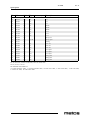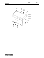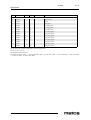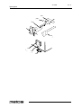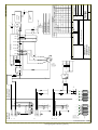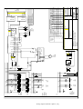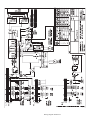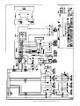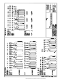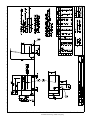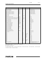
1
BRATT PAN
FUTURA PE
FUTURA PES
FUTURA PED
TYPE: 60, 85, 110
Accessories
HEIGHT ADJUSTMENT
Installation and Operation Manual
S/N: 095441/01
Valid from: 13.10.2009
Rev.: 3.6
26.10.2009
Rev.
1. General .......................................................................................................... 1
1.1 Symbols used in the manual .......................................................................................... 1
1.2 Symbols used on the appliance ...................................................................................... 1
1.3 Checking the relationship of the appliance and the manual .......................................... 1
2. Safety .............................................................................................................. 2
2.1 Safe use of the appliance ............................................................................................... 2
2.2 Safety instructions in case of malfunction ..................................................................... 2
2.3 Disposal of the appliance ............................................................................................... 2
3. Functional description .................................................................................. 3
3.1 Intended use of the appliance ........................................................................................ 3
3.1.1 Use for other purposes ........................................................................................... 3
3.2 Operating principle ........................................................................................................ 3
4. Operation instructions ................................................................................. 4
4.1 Before use ......................................................................................................................
4.1.1 Preparing the use ....................................................................................................
4.2 Operation .......................................................................................................................
4.2.1 Switching on the bratt pan .....................................................................................
4.2.2 Setting of the frying temperature ..........................................................................
4.2.3 Frying temperature .................................................................................................
4.2.4 Tilting ....................................................................................................................
4.2.5 Adjusting the working height ................................................................................
4.3 After use ........................................................................................................................
4.3.1 Cleaning .................................................................................................................
4.3.2 Service ...................................................................................................................
4
4
4
4
5
6
6
7
7
7
8
5. Installation ..................................................................................................... 9
5.1 Transporting and unpacking the bratt pan ..................................................................... 9
5.2 Positioning the bratt pan ................................................................................................ 9
5.3 Electrical connections .................................................................................................... 9
5.4 Test-run ....................................................................................................................... 10
6. Troubleshooting .......................................................................................... 11
26.10.2009
Rev.
7. Spare parts .................................................................................................. 13
7.1 Voltage codes .............................................................................................................. 15
7.2 Product codes ............................................................................................................... 15
8. Technical specifications .............................................................................. 29
26.10.2009
Rev. 3.6
General
1. General
Carefully read the instructions in this manual as they contain important information regarding proper, efficient and safe installation, use and maintenance of the appliance.
Keep this manual in a safe place for eventual use by other operators of the appliance.
The installation of this appliance must be carried out in accordance with the manufacturer’s instructions and following local regulations. The connection of the appliance to the
electric and water supply must be carried out by qualified persons only.
Persons using this appliance should be specifically trained in its operation.
Switch off the appliance in case of failure or malfunction. The periodical function checks
requested in the manual must be carried out according to the instructions. Have the appliance serviced by a technically qualified person authorized by the manufacturer and using
original spare parts.
Not complying with the above may put the safety of the appliance in danger.
1.1
Symbols used in the manual
This symbol informs about a situation where a safety risk might be at hand. Given instructions are mandatory in order to prevent injury.
This symbol informs about the right way to perform in order to prevent bad results, appliance damage or hazardous situations.
This symbol informs about recommendations and hints that help to get the best performance out of the appliance.
1.2
Symbols used on the appliance
This symbol on a part informs about electrical terminals behind the part. The removal of
the part must be carried out by qualified persons only.
1.3
Checking the relationship of the appliance and the manual
The rating plate of the appliance indicates the serial number of the appliance. If the manuals are missing, it is possible to order new ones from the manufacturer or the local representative. When ordering new manuals it is essential to quote the serial number shown
on the rating plate.
1
26.10.2009
Rev. 3.6
Safety
2. Safety
2.1
Safe use of the appliance
Because the bratt pan is a heated appliance that has hot surfaces during normal use, the
following warnings and instructions must be followed to avoid burns.
•
•
•
•
2.2
During long-time operation even the sides of the frying surfaces, the pouring lip
and the lid get hot.
For safe frying, always use heat protective gloves and appropriate accessories.
Look out for discharging steam when opening the lid, especially when simmering
or stewing.
Do not leave the bratt pan on for long periods totally without supervision.
Safety instructions in case of malfunction
Switch off the appliance if it is damaged or malfunctioning. Contact authorised service
personnel using original spare parts for service of the appliance.
2.3
Disposal of the appliance
The destroying of the appliance when the end of its economical lifetime has been reached
must be carried out in accordance with local rules and regulations. Taking care of substances that might be harmful to the environment, if not properly handled, and utilization
of reusable materials is best done by using professional personnel specializing in recycling.
2
26.10.2009
Rev. 3.6
Functional description
3. Functional description
3.1
Intended use of the appliance
The Futura PE bratt pan is intended for heating and frying of food.
3.1.1
Use for other purposes
Use of the appliance for other purposes than stated above is prohibited.
The manufacturer of the appliance takes no responsibility for situations that may occur if
warnings and instructions in this manual are neglected.
3.2
Operating principle
The frying surface of the bratt pan is heated by specially designed heating elements that
are controlled electronically in order to achieve a fast temperature response.
In the two larger bratt pans, PE 85 and PE 110, the frying surface is divided into two frying
zones. The temperatures of both zones can be controlled individually. The set temperature
is shown on a digital display, one for each frying zone.
The tilting of the bratt pan is electrical and it is controlled by a foot-operated tilting pedal.
Bratt pan models with the letter H in the type marking are equipped with the possibility
to adjust the working height of the bratt pan.
3
26.10.2009
Rev. 3.6
Operation instructions
4. Operation instructions
4.1
4.1.1
Before use
Preparing the use
The frying surface of the bratt pan is protected with a thin layer of grease during storage
and transportation. Before first-time use the grease must be removed by using hot water
and detergent.
After the cleaning, the frying surface must be burned in with salt-free grease. Heat up the
pan to 200°C keeping the lid closed. Burn the grease for 5-10 minutes, let the pan cool
down and wipe off excessive grease. Repeat when necessary. Do not use oil for burning.
Heated oil would create a tough surface, which is difficult to clean. A well greased pan
reduces fat consumption in frying and minimises burning of foodstuffs.
4.2
4.2.1
Operation
Switching on the bratt pan
During the installation, a mains switch may have been fitted near the bratt pan, often on a
wall nearby. Check that the mains switch is in the ON position.
The bratt pan is controlled from the operating panel and with a tilting pedal.
1
3
4
2
Operating devices
1.
Operating panel
2.
Tilting pedal
4
2
26.10.2009
Rev. 3.6
Operation instructions
3.
4.
Tilting
Return
The pan is switched on by pressing the ON/OFF button, whereafter
•
•
•
the heating-up starts
the green pilot light goes on
the temperature displays show the preset temperature of 180°C (only one display
in model PE 60).
2
7
3
4
5
1
6
Operating panel
1.
ON/OFF button
2.
Green pilot light PAN SWITCHED ON
3.
Red temperature display (PE 60, PE 85, PE 110)
4.
Setting buttons for temperature (PE 60, PE 85, PE 110)
5.
Red temperature display (PE 85, PE 110)
6.
Setting buttons for temperature (PE 85, PE 110)
7.
Adjustment of working height (only H models)
Heating up to the frying temperature takes about 5-6 minutes. The preset frying temperature is flashing on the display until the temperature is about 30°C under the frying temperature.
Due to the very short preheating time of the bratt pan, energy can be saved by not switching the pan on until the frying is started. If there is a longer pause during the frying, the
bratt pan can be switched off or the temperature can be set to a lower value. Energy can
also be saved by keeping the lid closed always when possible, for instance when simmering or stewing.
4.2.2
Setting of the frying temperature
PE 60: The frying temperature can be changed by using the “+” and “-” buttons.
PE 85 and PE 110:
The frying temperature can be changed as follows:
•
•
Set the temperature for the desired zone with the “+” and “-” buttons.
Repeat for the other zone when needed.
5
26.10.2009
Rev. 3.6
Operation instructions
•
The heating-up of the other zone can be switched off by setting the temperature to
0°C.
The preset frying temperature 180°C remains in memory and is activated for use by
switching off the pan with the ON/OFF button and then turning it on again.
During long-time use, heat is transferred from one zone to the other. Although one zone
would be switched off, it gets gradually warm, reaching a temperature that is about half
of the temperature of the heated zone. If so desired, the temperature of this zone can be
checked by searching with the setting buttons the area where the temperature display stops
flashing (±30°C).
4.2.3
Frying temperature
Guiding temperatures for various products:
Fried eggs
Omelette
Fish
Bacon
Meat cubes
Meat balls, depending on size
Hamburgers, depending on size
Veal fillet
Wiennasteak
Thin steak of veal
Broiler, in big pieces
Floured slices of liver
Chops
Sausage cubes
Frankfurters
Fried potatoes
Mushrooms
Onion
Small pancakes
4.2.4
150°C
160°C
170°C
150°C
170°C
130°C - 170°C
130°C - 170°C
170°C
170°C
220°C
150°C
170°C
170°C
130°C - 150°C
150°C
150°C - 170°C
130°C - 150°C
140°C
170°C
Tilting
Before tilting or returning the bratt pan to the working position, check that nothing is in
the movement area or leaning against the moving part of the bratt pan.
The electric tilting of the pan is operated with a foot pedal (Figure “Operating devices” in
Section “Switching on the bratt pan”). The pan tilts as long as the pedal is pushed downwards. By lifting the pedal upwards, the pan returns to the horizontal position. The pan
cannot be tilted while the lid is closed.
When tilting the pan, the heating is switched off and will be switched on again when the
pan is in the horizontal position.
6
26.10.2009
Rev. 3.6
Operation instructions
4.2.5
Adjusting the working height
Before adjusting the working height of the bratt pan, check that nothing is in the movement area or leaning against the moving part of the bratt pan.
Adjustment of the working height is possible in bratt pan models with letter H included
in the model marking. These models have two push buttons on the operating panel for the
option (Figure “Operating panel” in Section “Switching on the bratt pan”).
The working height can be electrically adjusted to the desired height by pushing the corresponding button. The working height is adjustable between 800-940 mm. [valid from
SN 25440/1]
Adjustment is not possible if the pan is in a tilted position.
4.3
After use
4.3.1
Cleaning
Burned deposits on the frying surface of the pan form an isolating layer which slows up
the frying and creates poor frying results. A clean frying surface is a must for good-quality
results.
The effect of burned deposits on the surface temperature: 2 mm of deposits lower the surface temperature with 24 %.
180°C
about 135°C
Cleaning equipment: scraper, hard brush, scouring plate, towel, kitchen paper
Cleaning detergent: slightly alkaline detergent (pH 8-10)
Cleaning method: scraping, dry, wet, damp
Precleaning:
Scrape out frying remains and wipe out grease and loose remains with paper. When necessary, pour hot water into the pan and let soak.
Cleaning:
The inside of the pan is cleaned with a brush and hot water. Spots are removed with a
scouring plate. Cleaning detergent should be used only for frying surfaces extremely covered with burned deposits, because it removes grease from the frying surface.
Inner and outer surfaces of the lid are cleaned with a brush and cleaning detergent solution. Pay special attention to the edges and hinges of the lid. The base and outer surfaces
of the pan are cleaned with a brush and cleaning detergent solution and rinsed with water.
7
26.10.2009
Rev. 3.6
Operation instructions
The frying surface of the pan is rinsed with hot water, dried by heating up and greased
with salt-free grease. All other surfaces are rinsed and wiped dry.
Water usage on the control panel and the electric box must be avoided.
Use of a water hose or pressure cleaning jet is strictly forbidden.
In order to remain in good condition, the frying surface must be burned with salt-free
grease when the pan is taken into use for the first time, and after that at intervals during
use. This is especially necessary in connection with thorough cleaning.
4.3.2
Service
Switch the appliance off if it is damaged or is malfunctioning. Contact authorised service
personnel using original spare parts for service of the appliance.
The appliance does not include any user serviceable parts inside. Service must be left to
authorised service personnel.
8
26.10.2009
Rev. 3.6
Installation
5. Installation
5.1
Transporting and unpacking the bratt pan
The best way to move the bratt pan is to keep it in its own package as long as possible
while it also protects the pan from outer damage. If it is necessary to unpack the pan, possible lifting must thereafter be done from the bottom frame of the base by using suitable
spacers of wood. In order to avoid damage, it is not allowed to use the lid as a workbench
during installation.
When unpacking the H-models of the bratt pan, it is very important to remove the two
transportation supports made of veneer.
5.2
Positioning the bratt pan
The installation is started by moving the pan exactly to the right installation spot considering a possible floor drain. The distances needed are shown in the installation drawing.
For service, most pans can be accessed from the front.
Thereafter the pan is adjusted into a horizontal position by turning the adjustable legs. The
correct position is checked from the frying surface, not from the outer edges of the pan.
When adjusting, consider that there must be a clearance between the tilting foot pedal and
the floor that allows handling of the pedal with the tip of a workshoe. The space between
the pan and the base is correctly set by these bolts.
When the bratt pan is on the correct location and in a horizontal position, it must be bolted
to the floor, the land models by the flanges in the rear adjusting legs and the marine models by all four leg flanges.
5.3 Electrical connections
In order to make eventual future service easier and to increase safety, a mains switch must
be installed near the appliance. This switch must disconnect the appliance completely
from the electrical supply network.
The feedthrough grommet for the connection cable is located on the bottom plate of the
base, just under the connection terminal as shown in the installation drawing. In order to
make the connection, the lower front siding must be removed by loosening the two screws
that are located on the lower edge of the siding and then lifting the siding upwards.
9
26.10.2009
Rev. 3.6
Installation
5.4
Test-run
Besides the live electrical parts also look out for possible moving mechanisms in the lower part of the appliance, if there is a need for testing the appliance during installation while
the guards or cover plates are detached.
Make sure that the protective grease has been removed from the frying surface before taking the pan into use. See “Preparing the use”.
After connecting the cable check the function of the bratt pan by turning it on with the
ON/OFF button.
Check that
•
•
the temperature displays of both heating zones (only one zone in the model PE 60)
flashes the set reading which after a few minutes stays continuously on.
the limit switches of the tilting and heating work properly: When tilting the heating
is switched off, in the fully tilted position tilting stops and the power is cut from
the tilting motor. The return movement stops when the pan reaches the base, the
heating is switched on and the power is cut from the tilting motor. If necessary, adjust the limit switches.
Before refitting the front siding, check that no wires in the base interfere with moving
parts.
Refit the lower front siding.
10
26.10.2009
Rev. 3.6
Troubleshooting
6. Troubleshooting
If the appliance does not function, check the following:
•
•
•
Has the appliance been used according to the instructions?
Are all possibly removable parts refitted?
Are the mains switch on the appliance or nearby - often on the wall - in the ON
position?
If even this does not help, figure out in advance how to briefly describe the break-down
and contact an authorized service person.
The appliance does not include any user serviceable parts inside. Service must be left to
authorized service personnel.
11
26.10.2009
Troubleshooting
12
Rev. 3.6
26.10.2009
Rev. 3.6
Spare parts
7. Spare parts
General parts PE .................................. 17
General parts PE .................................. 19
Tilting device PE................................... 21
Height adjustment device PE .............. 23
Electrical components PE.................... 25
Electrical components PE.................... 27
13
26.10.2009
Spare parts
14
Rev. 3.6
26.10.2009
Rev. 3.6
Spare parts
Voltage
Voltage code
A
3/N/PE∼400/230V 50Hz
B
∼250V 16A 50Hz
C
3/N/PE∼380/220V 50Hz
D
3/PE∼200V 50-60Hz
F
2/PE 220−240V 50Hz
G
3/N/PE∼415/240V 50Hz
H
3/PE∼230V 50Hz
I
3/PE∼220V 60Hz
J
3/PE∼380 50Hz
K
3/PE∼400V 50Hz
L
3/PE∼415V 50Hz
M
3/PE∼440V 60Hz
N
3/PE∼460V 60Hz
O
3/PE∼480V 60Hz
P
1/N/PE~220-240V 50Hz
R
2/PE~220-230V 60Hz
S
3/N/PE∼400/230V 50Hz
T
3/PE∼230V 60Hz
U
1/N/PE~100V 50-60Hz
Product code
7.1
Voltage codes
7.2
Product codes
Full name
Model codes
PE
FUTURA PE
PES
FUTURA PES
PED
FUTURA PED
Type codes
60
60
85
85
110
110
Accessory codes
HE
HEIGHT ADJUSTMENT
15
26.10.2009
Spare parts
520
540
490
500
510
430
440
450
530
540
550, 560, 570,
580, 590, 600
610, 620, 630
730, 740, 750
720
700, 710
460
470
480
16
910
920
925
930
935
940
950
960
Rev. 3.6
26.10.2009
Rev. 3.6
Spare parts
ID
Code
Model Type Accessory
Description
Module:General parts PE
430
3492174
PE
60
Lid
440
3492167
PE
85
Lid
450
3492142
PE
110
Lid
460
3462405
PE
60
Handle
470
3462395
PE
85
Handle
480
3447559
PE
110
Handle
490
3491163
PE
60
Cover
500
3491188
PE
85
Cover
510
3447541
PE
110
Cover
85,110
Spring, right
520
3445279
PE
530
3445286
PE
540
3491117
PE
550
3469023
PE
Spring, left
Bearing
60
Rear case
560
3469048
PE
85
Rear case
570
3469055
PE
110
Rear case
580
3469104
PE
60
Cover plate
590
3469111
PE
85
Cover plate
600
3469129
PE
110
Cover plate
610
3490032
PE
60
Siding plate
620
3490057
PE
85
Siding plate
630
3490064
PE
110
Siding plate
PE=FUTURA PE, PES=FUTURA PES, PED=FUTURA PED
60=60, 85=85, 110=110
HE=HEIGHT ADJUSTMENT
A=3/N/PE∼400/230V 50Hz, C=3/N/PE∼380/220V 50Hz, H=3/PE∼230V 50Hz, I=3/PE∼220V 60Hz, J=3/PE∼380 50Hz,
L=3/PE∼415V 50Hz, M=3/PE∼440V 60Hz
17
26.10.2009
Spare parts
520
540
490
500
510
430
440
450
530
540
550, 560, 570,
580, 590, 600
610, 620, 630
730, 740, 750
720
700, 710
460
470
480
18
910
920
925
930
935
940
950
960
Rev. 3.6
26.10.2009
Rev. 3.6
Spare parts
ID
Code
Model Type Accessory
Description
Module:General parts PE
700
3149538
PE
Adjustable leg
710
3205278
PE
Flange
720
3468975
PE
Siding plate
730
3468982
PE
60
Rear siding plate
740
3469009
PE
85
Rear siding plate
750
3469016
PE
110
Rear siding plate
910
3490145
PES
60
Front panel, upper
920
3490152
PES
85
Front panel, upper
925
3520583
PED
85
Front panel, upper
930
3490177
PES
110
Front panel, upper
935
3520618
PED
110
Front panel, upper
940
3490804
PE
60
Front panel, lower
950
3490811
PE
85
Front panel, lower
960
3490829
PE
110
Front panel, lower
PE=FUTURA PE, PES=FUTURA PES, PED=FUTURA PED
60=60, 85=85, 110=110
HE=HEIGHT ADJUSTMENT
A=3/N/PE∼400/230V 50Hz, C=3/N/PE∼380/220V 50Hz, H=3/PE∼230V 50Hz, I=3/PE∼220V 60Hz, J=3/PE∼380 50Hz,
L=3/PE∼415V 50Hz, M=3/PE∼440V 60Hz
19
26.10.2009
Spare parts
990
980
970
970
1010
990
1000
20
Rev. 3.6
26.10.2009
Rev. 3.6
Spare parts
ID
Code
Model Type
Accessory
Description
Module:Tilting device PE
970
3490674
PE
Motor
980
3490307
PE
Pin
990
3356848
PE
Cotter pin
1000
3492551
PE
Joint
1010
3490392
PE
Switch unit
PE=FUTURA PE, PES=FUTURA PES, PED=FUTURA PED
60=60, 85=85, 110=110
HE=HEIGHT ADJUSTMENT
A=3/N/PE∼400/230V 50Hz, C=3/N/PE∼380/220V 50Hz, H=3/PE∼230V 50Hz, I=3/PE∼220V 60Hz, J=3/PE∼380 50Hz,
L=3/PE∼415V 50Hz, M=3/PE∼440V 60Hz
21
26.10.2009
Spare parts
22
Rev. 3.6
26.10.2009
Rev. 3.6
Spare parts
ID
Code
Model Type
Accessory Description
Module:Height adjustment device PE
1020
3751330
PE
85,110
HE
Motor unit
1025
3751331
PE
85,110
HE
Motor drive
1030
3490628
PE
85,110
HE
Pump unit
1040
3490603
PE
85,110
HE
Cylinder
1050
3490642
PE
85,110
HE
3-pole connector
PE=FUTURA PE, PES=FUTURA PES, PED=FUTURA PED
60=60, 85=85, 110=110
HE=HEIGHT ADJUSTMENT
A=3/N/PE∼400/230V 50Hz, C=3/N/PE∼380/220V 50Hz, H=3/PE∼230V 50Hz, I=3/PE∼220V 60Hz, J=3/PE∼380 50Hz,
L=3/PE∼415V 50Hz, M=3/PE∼440V 60Hz
23
26.10.2009
Rev. 3.6
Spare parts
1210
810
1230
1110
1130
1070
1080
80
90
1170
410
1190
1220
1200
900
1090
1180
1100
1060 1160
24
26.10.2009
Rev. 3.6
Spare parts
ID
Code
Model Type
Accessory Description
Module:Electrical components PE
80
3438748
PE
60
Contactor
90
3240709
PE
60
Contactor
100
3438297
PE
60
Cable
100
3438307
PE
60
Cable
410
3092296
PE
60
Microswitch
810
3469714
PE
60
Heating element 4 kW
900
3347378
PE
60
Transformer
1065
3750636
PE
60
Relay card
1066
3750727
PE
60
Relay card socket
1070
3512046
PE
60
Fuse
1070
3512046
PE
60
Fuse
1080
3512053
PE
60
Fuse
1090
3438089
PE
60
Circuit board
1100
3438071
PE
60
Circuit board
1110
3438113
PE
60
Circuit board
1130
3448979
PE
60
Panel
1160
3438184
PE
60
Transformer
1170
3339786
PE
60
RC protector
1180
3434334
PE
60
Rectifier bridge
1190
3145389
PE
60
Limit switch
1200
3439692
PE
60
Transformer
1210
3439357
PE
60
Sensor, complete
1220
3439928
PE
60
Flat cable 0,3m 16 poles
1230
3439935
PE
60
Flat cable 2,3m 20 poles
PE=FUTURA PE, PES=FUTURA PES, PED=FUTURA PED
60=60, 85=85, 110=110
HE=HEIGHT ADJUSTMENT
A=3/N/PE∼400/230V 50Hz, C=3/N/PE∼380/220V 50Hz, H=3/PE∼230V 50Hz, I=3/PE∼220V 60Hz, J=3/PE∼380 50Hz,
L=3/PE∼415V 50Hz, M=3/PE∼440V 60Hz
25
26.10.2009
Rev. 3.6
Spare parts
26
26.10.2009
Rev. 3.6
Spare parts
ID
Code
Model Type
Accessory
Description
Module:Electrical components PE
80
3438748
PE
85,110
Contactor
90
3240709
PE
85,110
Contactor
410
3092296
PE
85,110
Microswitch
810
3469714
PE
85
Heating element 4 kW
810
3469714
PE
110
Heating element 4 kW
820
3512952
PE
85
Heating element 4 kW
900
3347378
PE
85,110
Transformer
1065
3750636
PE
85,110
Relay card
1066
3750727
PE
85,110
Relay card socket
1070
3512046
PE
85,110
Fuse
1070
3512046
PE
85,110
Fuse
1080
3512053
PE
85,110
Fuse
1090
3438089
PE
85,110
Circuit board
1100
3438071
PE
85,110
Circuit board
1120
3438064
PE
85,110
Circuit board
1140
3448961
PE
85,110
1150
3448954
PE
85,110
Panel
HE
Panel
1160
3438184
PE
85,110
Transformer
1170
3339786
PE
85,110
RC protector
1180
3434334
PE
85,110
Rectifier bridge
1190
3145389
PE
85,110
Limit switch
1200
3439692
PE
85,110
Transformer
1210
3439357
PE
85,110
Sensor, complete
1220
3439928
PE
85,110
Flat cable 0,3m 16 poles
1230
3439935
PE
85,110
Flat cable 2,3m 20 poles
PE=FUTURA PE, PES=FUTURA PES, PED=FUTURA PED
60=60, 85=85, 110=110
HE=HEIGHT ADJUSTMENT
A=3/N/PE∼400/230V 50Hz, C=3/N/PE∼380/220V 50Hz, H=3/PE∼230V 50Hz, I=3/PE∼220V 60Hz, J=3/PE∼380 50Hz,
L=3/PE∼415V 50Hz, M=3/PE∼440V 60Hz
27
26.10.2009
Spare parts
28
Rev. 3.6
26.10.2009
Rev. 3.6
Technical specifications
8.
Technical specifications
Heating control, circuit board connections
Heating control
Heating control, circuit board connections
Wiring diagram T00558B4
Wiring diagram T00185A3
Wiring diagram T00184C3
Wiring diagram T00942C3
Main and control circuit 82947N83
Heating element connection 81591-83
Installation drawing 80800-63C
29
Heating control, circuit board connections [PE; 60]
1. Lämmityselementit
Värme-element
Heating elements
5. Säätökortti, vasen (1)
Styrkort, vänster
Regulation card
2. Lämmityselementtien kaapelit
Värme-elementens kablar
Cables to heating elements
6. Säätökortti, oikea (2)
Styrkort, höger
Regulation card, right
3. Termolangat (tuntoelin)
Termoelement (givare)
Thermocouple (sensor)
7. Vasemman vyöhykkeen ohjaus (1)
Vänstra zonens styrning
Left zone control
4. Relekortti
Reläkort
Relay card
8. Oikean vyöhykkeen ohjaus (2)
Högra zonens control
Right zone control
Heating control [PE; 85, 110]
Heating control, circuit board connections [PE; 85, 110]
$/,6b77<(0&9$$7,08626$7==/,6b77<0,.52.<7.6
0XXWRV
Wiring diagram T00558B4 [PE 60]
3(
/
/
/
/
/
/
3(
(
.
.
[:9
9
9
9
91
91
3(30
(
(
5/
.
.
.
1
.
((
((
+($7,1*(/(0(17&211(&7,21
.
.
.
.
5/
.
1
9
9
9
9
)
$
)
$
$
$
)
)
(
.
.
.
7 9$
9
5/
.
1
9
79$
/,1(
),/7(5
.
9
1
/
=
(
.
/2$'
$
9
9
$
)
/,1(
.
9
*
a
1
/
=
),/7(5
B
.
9
9
79$
79$
B
(
.
/2$'
.
9
9
9
B
9'&
.$//,6786
67-b/31,1*
7,/7,1*
0
79$
6
2VD
&6
6
1LPLW\V
6
9<g+<.(
$
.
$
5&
6
8339b501,1*
+($7,1*
/b00,7<6
6
=
.RRGL
3llSLLU
.SO
$LQH
a
a
a
a
1a
=
.RUYDD
7
0
3
.RUYDWWX
,YaPD[$
8
8
6 $2
+XRP
3PD[N:
8
8
%
722%
6XKGH
)+]
6bb7g36
5(*8/$725
1,0(//,6$5927
89
3KL
8
8 1a
.$$9,2
',$*5$0
1R
.<7.(17b.$$9,2,66$1
.<7.(17b.$$9,2,66$)8/26
&283/,1*,1',$*5$0)287
.<7.(17b.$$9,2,66$5,9,/
&283/,1*,1',$*5$07(50,1$/%/2&
33)XWXUD3(
7XRWH
32:(5212))
9<g+<.(
.\WNHQWlNDDYLRW13($&9+]
.RSSOLQJVVFKHPD3($&9+]
:LULQJGLDJUDP
.$//,6786
32:(55(/(33
3$/$8786
.25.(86</g6
2+-$869,57$3,,5,
&21752/&,5&8,7
.25.(86$/$6
3bb9,57$3,,5,
0$,1&,5&8,7
/
/
/
1
3(
1b<77g31
',63/$<
Wiring diagram T00185A3 [PE 60]
3(
/
/
/
[:9
(
.
9a
9a
5/
.
99a
1
.
.
91a
91a
3(30
/
/
/
3(
/
/
/
1
3(
.
.
.
(
1
5/
.
.
.
(
.
.
.
1
(
5/
.
((
((
.
.
9a
(
.
.
.
)
)
(
.
.
9
9
9
9
)
)
7 9$
9
9
79$
/,1(
1
/
1
),/7(5
')+)
=
/,1(
/2$'
1
/
=
9
),/7(5
6
9
9
79$
67-b/31,1*
7,/7,1*
9$&
0
2VD
6
9
9
9
79$
&
.$//,6786
/2$'
1LPLW\V
:LULQJGLDJUDP
.$//,6786
32:(55(/(33
3$/$8786
.\WNHQWlNDDYLR
.RSSOLQJVVFKHPD
.25.(86</g6
9<g+<.(
.
5&
6
89
.SO
3llSLLU
$LQH
8
8
1a
.RRGL
6
6bb7g36
5(*8/$725
1b<77g31
',63/$<
a
a
a
a
1a
.RUYDD
7
0
3
.RUYDWWX
,YaPD[$
8
8
6 $2
+XRP
3PD[N:
8 8
7$
6XKGH
1,0(//,6$5927
)+]
3KL
/b00,7<6
8339b501,1*
+($7,1*
.<7.(17b.$$9,2,66$1
.<7.(17b.$$9,2,66$)8/26
&283/,1*,1',$*5$0)287
.<7.(17b.$$9,2,66$5,9,/
&283/,1*,1',$*5$07(50,1$/%/2&
$
$
.$$9,2
',$*5$0
1R 9<g+<.(
33)8785$3(3529(12-$/$'
7XRWH
6
32:(5212))
=
2+-$869,57$3,,5,
&21752/&,5&8,7
%
$/,6b77<(0&9$$7,08626$7==
+$50$$
9,2/(77,
6,1,1(1
.25.(86$/$6
3bb9,57$3,,5,
0$,1&,5&8,7
0XXWRV
=
$/,6b77<(0&9$$7,08626$7==/,6b77<0,.52.<7.6
0XXWRV
Wiring diagram T00184C3 [PE 85, 110]
3(3(+
3(
/
/
/
3(3(+
9
6$5-$.<7.(17b
6(5,(6&211(&7,21
3(3(+
3(3(+
3(3(+
/
/
/
3(
9
9
6$5-$.<7.(17b
6(5,(6&211(&7,21
3(3(+
9
6$5-$.<7.(17b
6(5,(6&211(&7,21
.
.
(
N:9
N:9
((
N:9
N:9
N:9
N:9
((
.
((
(
N:9
N:9
((
N:9
N:9
N:9
N:9
(
((
.
(
N:9
N:9
.
N:9
((
N:9
N:9
N:9
N:9
(
(
(
N:9
(
N:9
.
(
$
9
9
9
9
$
)
$
$
)
)
)
N:9
7
9$
9
9
79$
$
9
9
$
)
/,1(
*
79$
/,1(
a
1
/
=
1
/
),/7(5
B
),/7(5
=
B
$
/2$'
/2$'
9
B
9
9
9
6
9
9
79$
9'&
.$//,6786
67-b/31,1*
0
79$
1
.$//,6786
&6
6
3$/$8786
2VD
6
32:(5212))
$
.
$
6
$
.
$
8339b501,1*
+($7,1*
/b00,7<6
5&
.RRGL
33)XWXUD3(
7XRWH
1LPLW\V
6
=
5&
a
3llSLLU
.SO
a
a
1a
%
%
$LQH
=
.RUYDD
7
0
3
6 $2
+XRP
.RUYDWWX
722&
6XKGH
3(
3(+
,YaPD[$
3PD[N:
8
8 8 8
.<7.(17b.$$9,2,66$1
.<7.(17b.$$9,2,66$)8/26
&283/,1*,1',$*5$0)287
.<7.(17b.$$9,2,66$5,9,/
&283/,1*,1',$*5$07(50,1$/%/2&
7(.1,6(7$59277(&+1,&$/9$/8(6
3(3(+
3(+
3(
89
3KL
)+]
3PD[N:
,YaPD[$
8 8
8 8
8
8
1a
.$$9,2
',$*5$0
1R
9<g+<.(
9<g+<.(
.\WNHQWlNDDYLRW13($&9+]
.RSSOLQJVVFKHPD3($&9+]
:LULQJGLDJUDP
.25.(86</g6
32:(55(/(33
.25.(86$/$6
/
/
/
1
3(
6bb7g36
5(*8/$725
6bb7g36
5(*8/$725
1b<77g31
',63/$<
Wiring diagram T00942 C3
Main and control circuit 82947N83 [PE; 85, 110]
Heating element connection 81591-83 [PM, PE]
Installation drawing 80800-63C [PE]
26.10.2009
Rev. 3.6
Technical specifications
Item
Model
Type
Voltage
Specification
Dimensions WxDxH
PM,PE
60
600x8000x940 mm
Dimensions WxDxH
PM,PE
85
850x800x940 mm
Dimensions WxDxH
PM,PE
110
1100x800x940 mm
Package dimensioner WxDxH
PM,PE
60
720x900x1200 mm
Package dimensioner WxDxH
PM,PE
85
980x900x1200 mm
Package dimensioner WxDxH
PM,PE
110
1220x900x1200 mm
Frying zones
PE
60
1 pc
Frying zones
PE
85,110
2 pcs
Height of frying zone sides
PM,PE
60
90 mm
Height of frying zone sides, shallow bratt pan PM,PE
85,110
90 mm
Height of frying zone sides, deep bratt pan
PM,PE
85,110
180 mm
Frying surface WxD
PM,PE
60
500x500 mm
Frying surface WxD
PM,PE
85
750x500 mm
Frying surface WxD
PM,PE
110
1000x500 mm
Temperature setting range
P,PM,PE
Weight without package
PM,PE
60
100 kg
0 - 220 °C
Weight without package
PE
85
140 kg
Weight without package
PE
110
170 kg
Weight with package
PM,PE
60
130 kg
Weight with package
PE
85
170 kg
Weight with package
PE
110
200 kg
Material of frying surface
Material of frying zone sides
steel
PM,PE
stainless steel
Outer surface
stainless steel
Power
PE
60
L
6,6 kW
Power
PE
60
C,I,J,M
7,4 kW
Power
PE
60
A,H
8,0 kW
Power
PE
85
C,I,J
11,0 kW
Power
PE
85
A,H
12,0 kW
Power
PE
85
M
12,2 kW
Power
PE
110
L
13,1 kW
Power
PE
110
C,I,J,M
14,7 kW
Power
PE
110
A,H
16,0 kW
Operating conditions
Normal commercial kitchen conditions, temperature over 0 °C
PE=FUTURA PE, PES=FUTURA PES, PED=FUTURA PED
60=60, 85=85, 110=110
HE=HEIGHT ADJUSTMENT
A=3/N/PE∼400/230V 50Hz, C=3/N/PE∼380/220V 50Hz, H=3/PE∼230V 50Hz, I=3/PE∼220V 60Hz, J=3/PE∼380 50Hz,
L=3/PE∼415V 50Hz, M=3/PE∼440V 60Hz
40