1
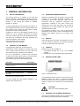
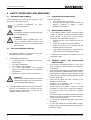
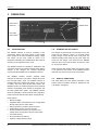
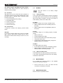
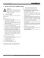
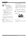
USERS MANUAL Mass Charger Alarm Interface GMDSS - Global Maritime Distress & Safety System MASTERVOLT Snijdersbergweg 93, 1105 AN Amsterdam The Netherlands Tel.: +31-20-3422100 Fax.: +31-20-6971006 www.mastervolt.com ENGLISH: PAGE 1 Copyright © 2013 Mastervolt, v 2.1 January 2013 TABLE OF CONTENTS TABLE OF CONTENTS: v 2.1 January 2013 1 GENERAL INFORMATION.............................................................................................................................................. 3 1.1 Use of this manual.............................................................................................................................................. 3 1.2 Validity of this manual ........................................................................................................................................ 3 1.3 Guarantee specifications .................................................................................................................................... 3 1.4 Quality ................................................................................................................................................................ 3 1.5 Liability ............................................................................................................................................................... 3 1.6 Identification label ............................................................................................................................................... 3 1.7 Changes to the GMDSS Interface ...................................................................................................................... 3 2 SAFETY GUIDELINES AND MEASURES ...................................................................................................................... 4 2.1 Warnings and symbols ....................................................................................................................................... 4 2.2 Use for intended purpose ................................................................................................................................... 4 2.3 Organizational measures ................................................................................................................................... 4 2.4 Maintenance & repair ......................................................................................................................................... 4 2.5 General safety and installation precautions ........................................................................................................ 4 2.6 Warning regarding life support applications........................................................................................................ 5 2.7 Warning regarding the use of batteries. ............................................................................................................. 5 3 OPERATION .................................................................................................................................................................... 6 3.1 Introduction......................................................................................................................................................... 6 3.2 Storage of set points .......................................................................................................................................... 6 3.3 Display functions ................................................................................................................................................ 6 3.3.1 Main Menu ......................................................................................................................................... 7 3.3.2 Install menu ....................................................................................................................................... 7 3.4 Alarms ................................................................................................................................................................ 9 3.4.1 Alarms handling ................................................................................................................................. 9 3.4.2 Mute the audible alarm ...................................................................................................................... 9 3.5 Maintenance ....................................................................................................................................................... 9 3.6 Problem solving .................................................................................................................................................. 9 4 INSTALLATION AND COMMISSIONING...................................................................................................................... 10 4.1 Things you need ............................................................................................................................................... 10 4.2 Directions for installation .................................................................................................................................. 10 4.3 Connection ....................................................................................................................................................... 11 4.4 Installation drawing ........................................................................................................................................... 12 4.5 Settings on the battery charger ........................................................................................................................ 13 4.6 Commissioning ................................................................................................................................................. 14 4.7 Decommissioning ............................................................................................................................................. 14 4.8 Storage and transportation ............................................................................................................................... 14 4.9 Re-installation................................................................................................................................................... 14 5 TROUBLE SHOOTING .................................................................................................................................................. 15 6 TECHNICAL DATA ........................................................................................................................................................ 16 6.1 Wiring details GMDSS interface ....................................................................................................................... 16 6.2 Technical specifications ................................................................................................................................... 17 6.3 Ordering Information ........................................................................................................................................ 17 7 EC DECLARATION OF CONFORMITY ........................................................................................................................ 18 2 Copyright © 2013 Mastervolt / January 2013 / GMDSS Mass Charger Alarm Interface Copyright / EN GENERAL INFORMATION 1 GENERAL INFORMATION 1.1 USE OF THIS MANUAL 1.3 This manual serves as a guideline for the safe and effective operation, maintenance and possible correction of minor malfunctions of the GMDSS Mass Charger Alarm Interface, in this manual also named as “GMDSS Interface” or “product” It is therefore obligatory that every person who works on or with the GMDSS Interface must be completely familiar with the contents of this manual, and that he/she carefully follows the instructions contained herein. Installation of, and work on the GMDSS Interface may be carried out only by qualified, authorised and trained personnel, consistent with the locally applicable standards and taking into consideration the safety guidelines and measures (chapter 2 of this manual). Keep this manual at a secure place! The English version has 20 pages. 1.2 GUARANTEE SPECIFICATIONS Mastervolt guarantees that the product has been built according to the legally applicable standards and specifications. Should work take place, which is not in accordance with the guidelines, instructions and specifications contained in this users manual, then damage may occur and/or the product may not fulfil its specifications. All of these matters may mean that the guarantee becomes invalid. The guarantee is limited to the costs of repair and/or replacement of the product. Costs for installation labour or shipping of the defective parts are not covered by this guarantee. 1.4 QUALITY During their production and prior to their delivery, all of our units are tested and inspected. The standard guarantee period is two years after date of purchase. VALIDITY OF THIS MANUAL Copyright © 2011 Mastervolt. All rights reserved. Reproduction, transfer, distribution or storage of part or all of the contents in this document in any form without the prior written permission of Mastervolt is prohibited. All of the specifications, provisions and instructions contained in this manual apply solely to standard versions of the GMDSS Interface delivered by Mastervolt. This manual is only valid for the following models: Description GMDSS Interface incl. top cover C1 enlarged cabinet GMDSS Interface incl. top cover C2 GMDSS Interface incl. top cover C3 MasterVision GMDSS Interface MV GMDSS-Interface panel Front Mounting 1.5 LIABILITY Mastervolt can accept no liability for: • consequential damage due to use of the GMDSS Interface; • possible errors in the manuals and the results thereof. 1.6 IDENTIFICATION LABEL Part number 21709150* 21709200* 21709300* 70400050 70400060 * This version of the GMDSS Interface may be delivered as an integrated part in the casing of a Mass battery charger For other models see other manuals available on our website: www.mastervolt.com Figure 1: Identification label The identification label is located on the rear side of the GMDSS Interface (see figure 1) Important technical information required for service, maintenance & secondary delivery of parts can be derived from the identification label. CAUTION! Never remove the identification label. 1.7 CHANGES TO THE GMDSS INTERFACE Changes to the GMDSS Interface may be carried out only after obtaining the written permission of Mastervolt. EN / GMDSS Mass Charger Alarm Interface / January 2013 / Copyright © 2013 Mastervolt 3 SAFETY GUIDELINES AND MEASURES 2 SAFETY GUIDELINES AND MEASURES 2.1 WARNINGS AND SYMBOLS 2.3 Safety instructions and warnings are marked in this manual by the following pictograms: A procedure, circumstance, deserves extra attention. etc which The user must always: • have access to the user's manual; • be familiar with the contents of this manual. This applies in particular to chapter 2, Safety Guidelines and Measures. CAUTION! 2.4 Special data, restrictions and rules with regard to preventing damage. 1 If the GMDSS Interface and/or the Mass Battery Charger is switched off during maintenance and/or repair activities, it should be secured against unexpected and unintentional switching on: • Remove and tag out the fuse(s) from the AC supply or; • Switch off and tag out the AC circuit breaker; • Switch off and tag out the connection with the batteries and remove the fuses; • Take adequate precautions to ensure that third parties cannot reverse the measures taken. 2 If maintenance and repairs are required, use only original spare parts. WARNING A WARNING refers to possible injury to the user or significant material damage to the charger if the user does not (carefully) follow the procedures. 2.2 1 2 USE FOR INTENDED PURPOSE The GMDSS Interface is constructed as per the applicable safety-technical guidelines. Use the GMDSS Interface only: • In combination with a Mastervolt Mass series battery charger • in an approved application • in a technical correct condition; • in a closed, well-ventilated room, protected against rain, moisture, dust and non condensing circumstances; • observing the instructions in the user’s manual 2.5 • • WARNING 3 Never use the GMDSS Interface in situations where there is danger of gas or dust explosion or potentially flammable products! • Use of the GMDSS Interface other than mentioned in point 2 is not considered to be consistent with the intended purpose. Mastervolt is not liable for any damage resulting from the above. • • • • • 4 ORGANIZATIONAL MEASURES MAINTENANCE & REPAIR GENERAL SAFETY AND INSTALLATION PRECAUTIONS Do not expose the GMDSS Interface to rain, snow, spray, moisture, excessive pollution and condensing circumstances. Short circuiting or reversing polarity will lead to serious damage to batteries, GMDSS Interface and the wiring. Fuses between the batteries and the Interface can not prevent damage caused by reversed polarity and the warranty will be void. Protect the DC wiring with fuses, according to the guidelines in this manual. Connection and protection must be done in accordance with local standards. Do not work on the Interface or system if it is still connected to a power source. Only allow changes in your electrical system to be carried out by qualified electricians. Check the wiring and connections at least once a year. Defects such as loose connections, burned cables etc. must be corrected immediately. Do not touch the equipment when wet or if your hands are clammy. To open the cabinet of the Mass Battery Charger, follow the instructions as stated in the user’s manual of the battery charger. Copyright © 2013 Mastervolt / January 2013 / GMDSS Mass Charger Alarm Interface Copyright / EN SAFETY GUIDELINES AND MEASURES 2.6 WARNING REGARDING LIFE SUPPORT APPLICATIONS Mastervolt products are not sold for applications in any medical equipment intended for use as a component of any life support system unless a specific written agreement pertaining to such intended use is executed between the manufacturer and Mastervolt. Such agreement will require the equipment manufacturer either to contract additional reliability testing of the Interface parts and/or to commit to undertake such testing as a part of the manufacturing process. In addition the manufacturer must agree to indemnify and not hold Mastervolt responsible for any claims arising from the use of the GMDSS Interface parts in the life support equipment. 2.7 WARNING REGARDING BATTERIES. THE USE OF Excessive battery discharge and/or high charging voltages can cause serious damage to batteries. Do not exceed the recommended limits of discharge level of your batteries. Avoid short circuiting batteries, as this may result in explosion and fire hazard. Installation of the batteries and adjustments of the Battery charger and the GMDSS Interface should only be undertaken by authorised personnel! EN / GMDSS Mass Charger Alarm Interface / January 2013 / Copyright © 2013 Mastervolt 5 OPERATION 3 OPERATION Select button Green LED’s: status OK Audible Alarm Red LED’s: Status Alarm Mute button LCD display Figure 2: Operation of the GMDSS Interface 3.1 INTRODUCTION 3.2 The GMDSS Interface is used for monitoring of the accumulator battery and Mass charger of the backup power supply for the radio installations. Battery voltage and current can be made visible by means of an integrated LCD-display and audible failure alarms are set according to the regulations of the I.M.O. The GMDSS Interface is intended for installations with one battery bank and one Mastervolt Mass series battery charger. If two chargers are required, Mastervolt recommends the installation of two GMDSS interfaces. The GMDSS Interface contains separate alarm indicators for indication of AC failure, charger failure and low and high battery alarm. The GMDSS Interface is equipped with three potential free change over contacts to make a link to the ship’s global alarm system. The GMDSS Interface is standard equipped with an external 5V/50mA unregulated power supply for integration with the ships global alarm system. The GMDSS Interface offers the possibility to power external (LED-) indicators, buzzer and external mute switch (alarm accept) directly. STORAGE OF SET POINTS The charger set points F8 till F12 (see section 3.3.2) are stored into the EEprom memory of the Mass series battery charger. In case off loss of AC or DC power, the GMDSS interface reads back the set points which are stored into the charger. This means that the GMDSS interface will not loose the DC-alarm set points in case AC or DC power failure. Other set-points like display setting and charge current % are stored into the memory of the GMDSS Interface itself and may get lost in case of DC power failure. 3.3 DISPLAY FUNCTIONS The actual status and user specific information of the battery system and battery charger is displayed at the LCD display. See figure 2. Other features: • Display backlight; • Integrated Status LED indicators for DC voltage alarm, Charger alarm and AC mains alarm; • Easy programming of battery alarm set points • Audible alarm function with mute function; • Three potential-free switch over contacts for DC voltage alarm, Charger alarm and AC mains alarm; • Test mode function; • Shunt included in the delivery • Wide DC-voltage operating range 6 Copyright © 2013 Mastervolt / January 2013 / GMDSS Mass Charger Alarm Interface Copyright / EN OPERATION 3.3.1 Main Menu The Main Menu offers a quick status overview of the battery system and battery charger. It is immediately accessible by pressing the Select button shortly. None of the displayed information can be modified at this menu. There are two modes to display the measured parameters at the Main Menu: • Standard menu. If this mode is chosen, all below mentioned screens will be shown, except the screen marked with *. (Install menu, F2 = OFF) • Short menu. If this mode is chosen, the screens which are marked with ** will not be shown. (Install menu, F2 = ON) 3.3.2 Install menu The Install menu is used to adjust the GMDSS-Interface in accordance with the electrical installation. To enter the Install Menu, hold the Select button pressed for at least 1 second. To leave the Install Menu wait 20 seconds or scroll to RETURN and hold the Select button pressed until you return to the Main Menu. Touch the Select button shortly to scroll through the functions as described below. If a value can be adjusted, the display shows an arrow. When the arrow is pointing downwards (È) the displayed value can be decreased by pressing the Mute button shortly. If the arrow is pointing upwards (Ç) the value can be increased. To change the direction of this arrow, hold the Select button pressed until the pointing direction of the arrow changes. The desired mode can be selected at the Install menu, function F2 (see section 3.3.2). If the GMDSS Interface is adjusted to the Standard menu, and function F1: Scroll main menu is set to ON, scrolling through the Main Menu is done automatically. If the function F1: Scroll main menu is set to OFF, you can scroll through the Main Menu by touching the Select button shortly. M 24/25 Bulk 26.4V 024.0A CHG CUR. 089% BAT VOLT 26.4V BAT CUR. 024.0A To protect the GMDSS-Interface against unintended adjustment of set points, the Lock all settings function is activated every time you enter the Install menu. When activated (“ON”), the settings mentioned in this chapter cannot be changed. See F0 Lock all settings to unlock. Status charger Shows the model of the connected Mass series battery charger and the actual charge stage of the Three Stage Charge algorithm. Voltage and charge current* Shows the actual battery voltage (Volt) and the charge current (Amps). Charge current** Shows the actual charge current (%) as percentage of the nominal charge current. Battery voltage ** Shows the actual battery voltage (Volt). Battery current** Shows the actual charge current (Amps). F0: Lock all settings To unlock the settings of the GMDSS Interface, hold the Select button pressed until this function switches to OFF. Factory setting: ON Adjustable range: ON/OFF F1: Scroll main menu If this function is set to ON, scrolling through the Main Menu is done automatically. If set to OFF, you can scroll through the Main Menu manually by touching the Select button. Factory setting: ON Adjustable range: ON/OFF F2: Main menu short If this function is set to OFF, all screens mentioned in section 3.3.1 will be shown, except screen marked with *. If set to ON, screens marked with ** will not be shown. Factory setting: OFF Adjustable range: ON/OFF EN / GMDSS Mass Charger Alarm Interface / January 2013 / Copyright © 2013 Mastervolt 7 OPERATION F3: Scroll text When set to ON, the entire text of the function is displayed at the Install menu. When set to OFF, only the function number is displayed. Example for the Back light function. If F3: Scroll text set to OFF, “F7” will be displayed. If this function is set to ON “F7: Back light” will be displayed. Factory setting: OFF Adjustable range: ON/OFF F4: Buzzer active Press the Mute button shortly to toggle the operation of the Audible alarm. Factory setting: ON Adjustable range: ON/OFF F5: Prelow Alarm To enable the Pre-low alarm function, this setting must be switched to ON. See F13: Prelow Alarm 0…10% for details Factory setting: ON Adjustable range: ON/OFF F6: Software Version This function shows the installed software version of the GMDSS Interface; this value cannot be changed. F7: Back light If Backlight is set to Auto, the backlight of the display will switch off automatically if the buttons are not touched for 10 seconds. As soon as one of the buttons is touched, the display’s backlight and the LED-bar will be lit again for an easy reading of the display. Press the Mute button shortly to toggle this function. Factory setting: Auto Adjustable range: ON/OFF/Auto F8: Low Battery Alarm ON If the battery voltage drops below this value, the alarm function will be activated after the “Alarm Delay” time has elapsed; see F12. Factory setting: 10.0V/20.0V depending on the nominal battery voltage Adjustable range:8.0…18.0V/18.0…36.0V F9: Low Battery Alarm OFF When the battery voltage rises above this level after a Low Battery Alarm, the alarm function will be deactivated again. Factory setting: 11.0V/22.0V depending on the nominal battery voltage Adjustable range:8.0…18.0V/18.0…36.0V 8 F10: High Battery Alarm ON When the battery voltage rises above this level, the alarm function will be activated without delay. Factory setting: 16.0V/32.0V depending on the nominal battery voltage Adjustable range:8.0…18.0V/18.0…36.0V F11: High Battery Alarm OFF When the battery voltage drops below this level after a High Battery Alarm, the alarm function will be deactivated again. Factory setting: 15.5V/31.0V depending on the nominal battery voltage Adjustable range:8.0…18.0V/18.0…36.0V F12: Alarm delay Low Battery The “alarm delay time” can be set to delay the alarm function when the DC-voltage drops below the Low Battery Alarm On set point (F8). This delay is to prevent a false alarm as a result of a temporary voltage drop, because of switching on a heavy load. Factory setting: 30 seconds Adjustable range: 3…60 seconds F13: Prelow Alarm 0…10% The “Pre-low alarm level” marks the voltage below which the audible alarm is activated. This function can serve as a pre-warning before the battery voltage drops below the Low Battery Alarm ON level (Function F8) which will result in a DC-status alarm. Note that this threshold value is always above the Low Battery Alarm ON level (F8). Factory setting: 5% above the Low Battery Alarm On level Adjustable range:0…10% F14: Charger current control The Maximum charge current is set by default at the maximum charge current of the Mass series battery charger. Here you can adjust the maximum charge current Factory setting: 100% of the maximum charge current. Adjustable range: 20…100% F15: Charger in force float By default, the Mass series battery charger will charge the battery following a three stage charge program. For special applications, the battery charger allows you to change the three stage charge program to a single stage charging program by activating the function "Charger in force float” Refer to the User’s manual of the battery charger for details. Factory setting: OFF Adjustable range: ON/OFF Copyright © 2013 Mastervolt / January 2013 / GMDSS Mass Charger Alarm Interface Copyright / EN OPERATION F16: Restore charger and GMDSS to factory settings Hold the Mute button pressed for three seconds to restore the factory settings F17: Test alarm With this function you can check the correct operation of each alarm function and to test the audible alarm. Press the Mute button to simulate below mentioned alarm functions step by step. 0 = Test mode disabled (factory setting) 1 = Test Audible alarm 2 = Test DC voltage alarm, 3 = Test Charger alarm 4 = Test AC mains alarm F18: LCD Contrast To adjust the contrast of the display, press the Mute button. RETURN If you want to exit the Install menu to return to the Main Menu, hold the Select button pressed until you return. Else press the Select button shortly to return to F0: Lock all setting 3.4 ALARMS See also section 4.5 for battery charger settings. 3.4.1 Alarms handling If one of the below mentioned alarm functions is triggered, the audible alarm will be activated and the corresponding relay contact will be activated. The origin of the alarm is made visible by means of the status LED’s. DC Status. The battery voltage is out of range. Possible causes: • Battery voltage is below the Low Battery Alarm On level (F8) • Battery voltage is above the High Battery Alarm On level (F10) Charger The battery charger is not working properly. Possible causes: • Battery sense error • Charger temperature too high • Short circuit at the DC-output of the battery charger • Temperature sense error • Communication cable between battery charger and GMDSS Interface not connected AC Mains An AC Mains alarm may indicate: • No AC present at the AC input of the battery charger. • Battery charger is switched off by means of the ON/OFF switch on the battery charger 3.4.2 Mute the audible alarm The audible alarm is muted by pressing the mute button. A new event will reactivate the alarm sound. The display will show the alarm status. 3.5 MAINTENANCE For a reliable and optimum function of the GMDSS Interface, the following is required: • 3.6 Check at least once a year if all cable and wire connections are still firmly connected. PROBLEM SOLVING Refer to section 5 if a problem occurs EN / GMDSS Mass Charger Alarm Interface / January 2013 / Copyright © 2013 Mastervolt 9 INSTALLATION AND COMMISSIONING 4 INSTALLATION AND COMMISSIONING 4.2 WARNING During installation and commissioning of the GMDSS Interface, the Safety Guidelines & Measures are applicable at all times. See chapter 2 of this manual. 4.1 THINGS YOU NEED Make sure you have all the parts you need to install the GMDSS Interface: Materials: ; The GMDSS Interface (included); ; A 500Amp/50mV shunt (included) for the current measurement of the battery bank; A 6-wire modular communications cable (RJ12, cross wired) to connect the GMDSS-interface to the Mass series battery charger; 2x0.25mm² twisted pair wire, long enough to reach from the shunt to the GMDSS Interface; Wires 0.25mm² for voltage sensing of the battery bank and for the DC power supply of the GMDSS Interface Fuse holders with 2 A-T fuses to be integrated in the voltage sensing lines and the DC power supply; As short as possible heavy duty battery cable, finished with cable lugs, to run from the minus pole of the battery to the shunt. Cable thickness must be in accordance with the electrical installation. Refer to the installation manual of the Mass Battery charger for recommendations on DC-wiring; DIRECTIONS FOR INSTALLATION Obey the following stipulations during installation: • The GMDSS-Interface is designed for indoor use only; • Ambient temperature: 0 … 60°C / 32°F … 140°F; • Humidity: 0-95% non condensing; • The GMDSS Interface can be mounted into the enclosure of the Mastervolt Mass series battery charger or as remote panel (refer to specifications for ordering information); • Do not install the GMDSS Interface straight above the batteries because of possible corrosive sulphur fumes; • According to the regulations for GMDSS systems the panel must be installed at a position which is visible from where the ship is normally navigated; • For good visibility avoid installing the GMDSS Interface in direct sunlight; • The audible alarm and LED indicators, voltage and current meters can be powered by an independent DC power supply with operating voltage ranging from 8 to 32 VDC; • Keep all wires as short as possible; • Keep the voltage and current sensing wiring away from other noise producing conductors; • Take adequate measures to avoid corrosion of the wires and connections. We recommend as a minimum tool kit: A saw to make a cut-out in the instrument panel (part nos. 70400050 and 70400060 only); A wire cutter / stripper; A crimping tool for cable terminals; A cross-head screw driver; 2 mm and 5 mm flat blade screwdrivers. A complete set of spanners, pliers and wrenches may be helpful during the installation of the GMDSS Interface 10 Copyright © 2013 Mastervolt / January 2013 / GMDSS Mass Charger Alarm Interface Copyright / EN INSTALLATION AND COMMISSIONING 4.3 CONNECTION 6 Insert the RJ12 connector into modular socket at the rear side of the GMDSS Panel. 7 Insert the RJ12 connector on the other side of the communication cable into the RS232 port inside the connection compartment of the Mass series battery charger. Refer to the user’s manual of the Mass battery charger, section “Connection of accessories” for details. 8 Connect the other wiring of the GMDSS Interface as indicated in figure 4 but do not place the fuses yet! WARNING Disconnect the electrical power: • Switch off all consumers; • Switch off all charging systems; • Remove all battery fuses; • Check with a suitable voltmeter whether the entire DC installation is voltage free. 1 Depending on the model of the GMDSS Interface: • Make 168 x 53 mm cut out in the instrumentation panel, or • Integrate the GMDSS Interface in your Mastervision panel, or • Replace the existing the front cover plate of the battery charger by the GMDSS Interface 2 Install the shunt of the GMDSS Interface as close as possible to the battery bank. 3 Disconnect the wiring from the negative battery pole. 4 See figure 4. Place the shunt between the negative wires and the negative battery pole using the heavy duty battery cable. Do not exchange the DC wiring of the load side with the battery side. 5 Run the 6 pole modular communication cable between the battery charger and the GMDSS Interface. Do not exchange the twisted wires: the load side must be connected to terminal 5, the battery side must be connected to terminal 6. Battery cables must be connected here Twisted wires must be connected here Figure 3: Shunt connections. 9 Option: Connect the wiring of the auxiliary components such as potential free relay contacts. Refer to section 6.1. EN / GMDSS Mass Charger Alarm Interface / January 2013 / Copyright © 2013 Mastervolt 11 INSTALLATION AND COMMISSIONING 4.4 INSTALLATION DRAWING DC Load This schematic is to illustrate the general placement of the GMDSS Interface in a circuit. It is not meant to provide detailed wiring instructions for any particular electrical installation. Figure 4: Installation drawing of the GMDSS Interface 12 Copyright © 2013 Mastervolt / January 2013 / GMDSS Mass Charger Alarm Interface Copyright / EN INSTALLATION AND COMMISSIONING 4.5 SETTINGS ON THE BATTERY CHARGER To communicate correctly with the GMDSS interface, the continuous monitoring mode should be enabled on the Mass series battery charger: To do so, DIP-switches 1 + 2 of the Mass battery charger must be adjusted to the ON position Please note that when the Continuous monitoring mode is enabled, the micro processor in the battery charger will stay active and drain a very small current of ±25mA when the charger has no AC supply If the continuous monitoring mode is not enabled, the GMDSS Interface may show incorrect alarms! Figure 5: Location of the DIP-switches at battery charger model Mass 24/25-2 (DNV) Refer to the user’s manual of the Mass battery charger for details about adjustment of the DIP switches. Adjust the DIP-switches prior to commissioning of the battery charger! CAUTION! Invalid settings of the Mass Charger can cause serious damage to your batteries and/or the connected load! Adjustments of settings may be undertaken by authorised personnel only. Figure 6: Location of the DIP-switches at battery charger models Mass 12/60-2, Mass 12/80-2 and Mass 24/50-2 Figure 7: Location of the DIP-switches at battery charger models Mass 24/75 and Mass 24/100 EN / GMDSS Mass Charger Alarm Interface / January 2013 / Copyright © 2013 Mastervolt 13 INSTALLATION AND COMMISSIONING 4.6 COMMISSIONING 4.7 CAUTION! Check the polarity of all wiring before commissioning: plus connected to plus (red cables), minus connected to minus (black cables) Follow the steps described below to switch on the GMDSS Interface. If it is necessary to put the GMDSS Interface out of operation, follow the instructions in order of succession as described below: 1 2 3 4 Mount this assembly into the instrumentation panel 1 2 3 4 5 6 7 Tighten all cable glands of the battery charger to ensure the pull relief Check all wiring and connections Close the front cover plate of the battery charger. Beware that the wiring does not obstruct the cooling fans and air flow. If all wiring is OK, place the DC-fuse(s) to connect the Interface to the DC power supply The GMDSS Interface will switch on: an audible alarm can be heard, all LED’s will illuminate for a few seconds and a welcome message is shown on the display. If required, go to the Install menu to adjust the GMDSS-Interface in accordance with the electrical installation (refer to section 3.3.2) Test the alarm functions of the GMDSS Interface; see function F17 of the Install menu (refer to section 3.3.2) DECOMMISSIONING 5 Switch off the battery charger Remove the DC-fuse(s) of the DC-distribution and/or disconnect the batteries. Remove the fuses from the DC power supply and the voltage sensing wires Check with a suitable voltage meter whether the inputs and the outputs of the GMDSS Interface are voltage free. Disconnect all the wiring Now the GMDSS Interface can be demounted in a safe way. 4.8 STORAGE AND TRANSPORTATION When not installed, store the Interface in the original packing, in a dry and dust free environment. Always use the original packing for transportation. Contact your local Mastervolt Service Centre for further details if you want to return the apparatus for repair. 4.9 RE-INSTALLATION To reinstall the GMDSS Interface, follow the instructions as described in this chapter (chapter 4). Now the GMDSS Interface is ready for operation. 14 Copyright © 2013 Mastervolt / January 2013 / GMDSS Mass Charger Alarm Interface Copyright / EN TROUBLE SHOOTING 5 TROUBLE SHOOTING If you cannot solve a problem with the aid of this table, contact your local Mastervolt Service Centre. See www.mastervolt.com. Make sure you have the Article and serial number (see section 1.6) as well as the Software version (see section 3.3.2) of the GMDSS-Interface present if you have to contact your local Mastervolt Service Centre to solve a problem. Malfunction No display function Possible cause Error in the wiring No current measurement Error in the wiring Current measurement not accurate No load connected or batteries are full. Part of the load or charger is connected at the battery side of the shunt Distortion on the shunt wiring Corrosion on the shunt wiring Voltage reading shows 0,00 Error in the wiring Fuse (2A) blown Parameter settings can not be changed at the install menu Back light and LED-bar switch off after 10 seconds The GMDSS Interface shows incorrect alarms Battery voltage less than 8 Volt Batteries have been left standing without being used for a longer period Adjustment of settings is locked every time you enter the install menu. Setting for Backlight set to OFF Wrong setting of the parameters Wrong connection of relay contact Communication between the GMDSS-panel and the Battery charger was interrupted Alarm function is triggered by a short time voltage dip Audible alarm is not activated when an Alarm occurs. Wrong setting of the alarm delay time. Buzzer function deactivated. What to do Check wiring for errors especially the DC power supply (section 4.3, step 8) Check wiring for errors especially the twisted wires between the shunt and the panel (section 4.3, step 8) Check the load. Check whether all connections to the negative pole are connected at the load side of the shunt (section 4.3, step 4) Replace wiring by twisted pair cable between the shunt and the panel (section 4.3, step 8). Keep this wiring away from other nois producing conductors! Replace wiring Take adequate measures to avoid corrosion of the wires and connections! Check wiring for errors especially the voltage sense wires (section 4.3, step 8) Investigate the cause of the blown fuse. Then replace the fuse Charge the battery Recharge the batteries up to 100%. Unlock the settings of the GMDSS Interface (see section 3.3.2, F0) Press one of the buttons or refer to section 3.3.2, F7 to change the backlight settings. See section 3.3.2, F8 till F12 for the correct setting of the parameters. Connect the external relay to the correct terminals (see section 6.1) Enable the Continuous monitoring mode on the battery charger to keep alive the communication between the GMDSS-panel and the Battery charger (see section 4.5). Increase the delay time (see section 3.3.2, F12) Switch on buzzer function (see section 3.3.2, F4) EN / GMDSS Mass Charger Alarm Interface / January 2013 / Copyright © 2013 Mastervolt 15 TECHNICAL DATA 6 TECHNICAL DATA 6.1 WIRING DETAILS GMDSS INTERFACE 1 12 13 24 Figure 8: overview of the terminals Terminal 1 2 3 4 5 Designation – SUPPLY + SUPPLY – VSENSE + VSENSE LOAD SHUNT Description DC Power Supply input, 8-32 V DC 6 7 8 9 10 11 12 13 BAT SHUNT GND FAILURE REMOTE DC- FAILURE REMOTE CH- FAILURE REMOTE AC FAILURE REMOTE RST FAILURE REMOTE +BZ FAILURE REMOTE NO - DC ALARM 14 15 C - DC ALARM C NC - DC ALARM 16 NO – CHARGE ALARM 17 18 C - CHARGE ALARM NC - CHARGE ALARM 19 NO - AC ALARM 20 21 C - AC ALARM NC - AC ALARM 22 23 24 RJ12 X - NA EXT – 5V. /50mA EXT + 5V. /50mA Mass Charger QRS 232 Voltage Measurement 0..62V DC Current measurement 500A / 50mV Common GND for terminals 8 to 12 +5V / max 50mA output, active in case of DC Status alarm +5V / max 50mA output, active in case of Charger alarm +5V / max 50mA output, active in case of AC Mains Input external mute button +5V output for external mute button This contact is closed to C - DC ALARM (terminal 14) when the DC is in range (status: OK) Common This contact is closed to C - DC ALARM (terminal 14) when the DC is out of range (status: Alarm) This contact is closed to C – Charger (terminal 17) when the battery charger is working properly (status: OK) Common This contact is closed to C – Charger (terminal 17) when the battery charger is not working properly (status: Alarm) This contact is closed to C – AC mains (terminal 20) when the AC voltage is in range (status: OK) Common This contact is closed to C – AC mains (terminal 20) when the AC voltage is out of range (status: Alarm) Not connected GND Aux. Power supply +5V / max 50mA output Aux. Power supply (short circuit protected) QRS. 232 communication to Mass Charger, 6 pole, RJ12, cross wired See section 3.4 for an overview of conditions for the alarm functions 16 Copyright © 2013 Mastervolt / January 2013 / GMDSS Mass Charger Alarm Interface Copyright / EN TECHNICAL DATA 6.2 TECHNICAL SPECIFICATIONS Type: Model Article number Fits in Battery charger: Panel Dimensions (w x h x d) Dimensions shunt Weight Delivery includes: Function of instrument Manufacturer Number of battery sets Voltage Measurement Voltage accuracy Current Measurement Current accuracy Readout Supply voltage Supply current Safe compass distance Shunt Alarm contacts 6.3 Mass Charger Alarm Interface - GMDSS Interface MasterVision C1-enlarged cabinet C2 C3 70400050 21709150 21709200 21709300 n/a Mass 24/25-2 DNV Mass 12/60-2 Mass 24/75, (flush mounted panel) Mass 12/80-2 Mass 24/100 Mass 24/50-2 180 x 65 x 40 mm To be integrated in To be integrated in To be integrated in Cut-out: 168 x 53 mm the battery charger the battery charger the battery charger 84 x 44 x 44 mm - M8 84 x 44 x 44 mm - M8 84 x 44 x 44 mm - M8 84 x 44 x 44 mm - M8 400 gr (excl. shunt) 500 gr (excl. shunt); 500 gr (excl. shunt); 500 gr (excl. shunt); 1000 gr (incl. shunt) 1100 gr (incl. shunt) 1100 gr (incl. shunt) 1100 gr (incl. shunt) Interface, shunt, user’s manual Monitoring of the status of the battery and battery charger (12/24V DC) Mastervolt, Amsterdam, the Netherlands 1 0 – 62.7V DC (0.1V resolution); a 12V or 24V system is detected automatically. ± 0.2V @ 12V, ± 0.4V @ 24V - 500 … 500 Amp ± 2A (<45A), ± 4A (>45A) LCD display and status LED’s for DC voltage alarm, Charger alarm and AC mains alarm 8-32 V DC 110mA(@12V) / 65mA(@24V), Normal operation mode without activated relays Standard 1 meter; Steering: 0.3mm 500 Amp / 50 mV (included with the delivery) Potential-free switch over contacts for DC voltage alarm, Charger alarm and AC mains alarm, Maximum switching current: 1 Amp ORDERING INFORMATION Part number 39019052 6801601100 6801601200 Description Single shunt 500A/50mV* Cable 3x2x0.25 mm² twisted stranded wires (per meter) Cable 4x2x0.25 mm² twisted stranded wires (per meter) 6801601300 Cable 5x2x0.25 mm² twisted stranded wires (per meter) 6502001030 Modular RJ 12/ cross wired communication cable (6 m. / 19 ft.) 6502100100 Modular RJ 12/ cross wired communication cable (10 m. / 33 ft.) 6502100150 Modular RJ 12/ cross wired communication cable (15 m. / 48 ft.) * These parts are standard included with the delivery of the GMDSS Interface Mastervolt can offer a wide range of products for your electrical installation, including AGM batteries, GEL batteries, DC distribution kits, battery switches, battery cables, battery terminals and Mastervision switchboards See our website www.mastervolt.com for an extensive overview of all our products EN / GMDSS Mass Charger Alarm Interface / January 2013 / Copyright © 2013 Mastervolt 17 EC DECLARATION OF CONFORMITY 7 EC DECLARATION OF CONFORMITY We, Manufacturer Address Mastervolt Snijdersbergweg 93 1105 AN Amsterdam The Netherlands Declare under our sole responsibility that Product: 21709150* 21709200* 21709300* 70400050 70400060 GMDSS Interface incl. top cover C1 enlarged cabinet GMDSS Interface incl. top cover C2 GMDSS Interface incl. top cover C3 MasterVision GMDSS Interface MV GMDSS-Interface panel Front Mounting Is in conformity with the provisions of the following EC directives: • 2004/108/EC (EMC directive); the following harmonized standards have been applied: o EN 61000-6-3: 2007 Emission household equipment o EN 61000-6-2: 2007 Immunity industrial • 2006/95/EC (Safety directive); the following harmonized standard has been applied: o EN 60950-1:2001+ A11:2004 (Low voltage standard) Amsterdam, H.A. Poppelier Product Manager Marine & Mobile Mastervolt 10 18 Copyright © 2013 Mastervolt / January 2013 / GMDSS Mass Charger Alarm Interface Copyright / EN NOTES NOTES EN / GMDSS Mass Charger Alarm Interface / January 2013 / Copyright © 2013 Mastervolt 19 Snijdersbergweg 93, 1105 AN Amsterdam, The Netherlands Tel : + 31-20-3422100 Fax : + 31-20-6971006 Email : [email protected]