1
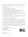
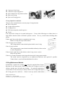
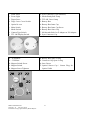
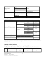
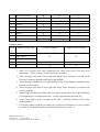
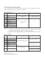
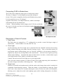
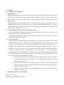
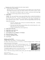
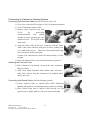
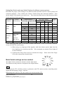
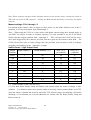
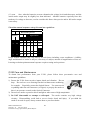
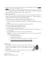
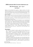
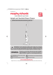
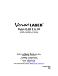
INON Z-220
Underwater TTL Auto-Strobe User Manual
Thank you for purchasing the Inon Z-220 Strobe. The Z-220 is an underwater TTL strobe with 22
Guide Number (ISO 100, Land); designed to be compatible with a variety of conventional film
based camera systems and digital camera systems.
The Z-220 is a complex, multi-function device with different features available for different camera
/ housing systems. Before learning more about how to use the Z-220 we recommend you read or
review your camera / housing manual(s) so that you thoroughly understand these components of
your system first. Then, we strongly advise you to read this Manual to become thoroughly
familiar with the Z-220, especially with regard to your particular camera system and applications.
In particular, to maintain optimum operation and performance of your Z-220, and for safety’s sake,
please pay close attention to the Warnings and Cautions, and preventative maintenance
recommendations. Failure to do so may cause flooding or damage to your strobe or camera
system, or personal injury to you or others.
CAUTION
This device is classified as a Class 3a Laser. It can cause injury if used incorrectly. To prevent
injury always follow these rules.
Never look into the laser beam window.
Never shine laser towards any person’s eyes.
Always turn off laser function and strobe power when not in use or when changing batteries.
Limited Warranty Statement
Inon warrants the Inon Z-220 Strobe for (1) one year from date of purchase for any manufacturing
defects. Inon will, at its discretion, repair or replace the strobe free of charge, during the warranty
INON Z-220 Manual
Version 1.41
Dec. 24, 2002
Translation Copyright 2002 by Mark Rupert
1
period, for manufacturing defects or repair matters where the strobe has been subject to normal use;
and, when operation, handling and maintenance have been conducted in accordance with this
manual.
Repair or replacement will not be free of charge in any other case, including the following:
1) When strobe is stolen or lost.
2) When strobe is damaged due to fire or natural disaster.
3) When strobe is damaged due to owner negligence.
4) When strobe has been modified or repaired at a facility not approved by Inon, or disassembled.
5) For consumable items such as O-rings, flash bulbs, or lost items such as screws, caps etc.
No other warranty, expressed or implied, applies to the Inon Z-220 Strobe.
Note: In principle, when strobe is purchased from Inon in Japan, the full Japanese warranty applies.
However, if strobe is shipped to Inon for repair or maintenance, the owner must bear transportation
costs both to and from Japan. In future, Inon may elect to direct owner to a local Inon authorized
service center for repair or maintenance.
Note: We highly recommend you obtain insurance to cover any Z-220 non-warranty issue, and to
protect against risk of loss or damage to your other equipment. Contact your local Inon
representative for suggestions on insurance options in your region.
Preventative measures to avoid accidental flooding
Before explaining how to use the many features of the Z-220 we recommend first understanding
some essential practices that will greatly reduce the main causes of accidentally flooding the Z-220.
The Z-220 is waterproof due to rubber O-rings that seal the internal circuitry from the elements.
However, O-rings require frequent inspection and care to ensure their watertight integrity. Since
most flooding occurs due an O-ring related problem we strongly recommend you inspect the
O-rings (and clean, grease or replace as necessary) each time before using the strobe. Equally
important are the O-ring contact surfaces. Check the contact surfaces for contaminants or
scratches. We cannot stress enough the importance of making O-ring related inspection and
maintenance a habit and essential part of your pre-dive equipment preparation routine.
O-Ring inspection locations
Inspect and maintain these O-rings and O-ring contact surfaces.
Battery Box O-ring
Battery Box O-ring groove
Battery Box O-ring contact surface
INON Z-220 Manual
Version 1.41
Dec. 24, 2002
Translation Copyright 2002 by Mark Rupert
2
Connector Cap O-ring
Connector Cap O-ring groove
Sync connector O-ring contact surface
Sync cord O-ring
Sync cord O-ring groove
O-ring inspection methods
These are the essential factors to ensure proper O-ring function:
The O-ring itself
O-ring contact surfaces
O-ring grooves
If O-ring is properly seated in groove
Grease
First, inspect the O-ring as it is seated in the groove. If any of the following are evident, there is a
high chance that the strobe will flood if placed in water. Be very careful about checking these
points:
If hair, sand, lint or other debris is attached to the O-ring
Remove O-ring and wipe-off the debris.
If the O-ring is cut or cracked
The O-ring must be removed and replaced with a new O-ring.
If the O-ring is twisted
The O-ring must be removed and reinstalled uniformly with no twists
or other irregularities.
If there is hair, sand, lint or other debris on the O-ring contact surface
Wipe off any debris.
If there is a scratch, blemish or other imperfection on the O-ring contact surface
The strobe must be inspected by an authorized technician, and repaired if possible.
Contact Inon or your local Inon distributor for advice.
O-Ring Maintenance Method
Periodically re-grease the O-rings only using the supplied Inon Grease.
Do not use any other grease, which may cause the O-rings to swell or
deform, causing poor seal and water leakage. For periodic maintenance
in the field it is not necessary to always remove the O-rings and inspect
the O-ring groove for each dive. If there is not any sand or other debris
INON Z-220 Manual
Version 1.41
Dec. 24, 2002
Translation Copyright 2002 by Mark Rupert
3
visible it is ok to lightly grease the O-ring while it is seated in the O-ring groove. For other
maintenance follow the instructions below.
Removing O-ring
If you need to remove an O-ring for replacement, inspection, or to check
the O-ring groove etc., lightly squeeze the O-ring from the sides (see
figure) so it bulges out from one side. Grasp the extended part and pull
to remove. Never use sharp or metal objects to remove O-rings as they
may damage the O-ring itself or the O-ring groove contact surface. If
squeezing the O-ring from both sides does not work, try gently using the
edge of a credit card or similar object, to pry the O-ring up a little so you
can grasp it. Then clean any residual grease or debris from the O-ring
groove and contact surface, and check the condition of both surfaces.
Wipe off the O-ring and determine is if is still useable or not.
Connector Cap O-ring, Sync Cord O-ring
After checking and confirming that the O-ring groove is clean and not
damaged, using your fingertips, apply a thin uniform film of Inon grease
on the O-ring. Install the O-ring in the groove, making sure that it is
seated uniformly and not twisted. Be careful not to get any grease on the
connector or cord terminals.
Battery Box O-ring
After checking and confirming that the O-ring groove is clean and not
damaged, using your fingertips, apply a thin uniform film of Inon grease
on the O-ring. Install the O-ring in the groove, making sure that it is
seated uniformly and not twisted. Then add a little extra grease to the
O-ring, and liberally grease O-ring contact surface on the battery box cap.
A little extra grease is necessary due to friction when screwing down the battery box cap. Slowly
screw down the battery box cap, making sure you don’t feel any excessive resistance, which could
mean the O-ring is binding or bearing too much friction.
INON Z-220 Manual
Version 1.41
Dec. 24, 2002
Translation Copyright 2002 by Mark Rupert
4
Z-220 Part Names
INON Z-220 Manual
Version 1.41
Dec. 24, 2002
Translation Copyright 2002 by Mark Rupert
5
1.
2.
3.
4.
5.
6.
7.
8.
9.
Flash Tubes
Focus Light
Target Laser
Target Laser Cover Switch
Optical Sensor
Main Switch
Mode Switch
Camera Type Switch
TTL OK Display Switch
18. –0.5Diffuser
19. –3 Diffuser
20. Magnet Switch Screw
21. Magnet Switch
22. Magnet Screw Tightener
INON Z-220 Manual
Version 1.41
Dec. 24, 2002
Translation Copyright 2002 by Mark Rupert
10. Sync Connector (5 pin Nikonos)
11. Strobe Ready Red Lamp
12. TTL OK Green Lamp
13. Battery Box
14. Battery Box Inner Cap
15. Battery Box Inner Cap Screw
16. Battery Box Outer Cap
17. M6 threaded hole for Z-Adapter or YS Adapter
23. Sync Connector Cap
24. Battery Box Spare O-ring
25. Connector Cap Spare O-ring
26. Inon Grease
27. Optical Sensor Cap / Sensor Plug for
Optical Cable
6
Z-220 Features
The Z-220 is a high performance, multi function TTL strobe with many features. Depending on
what camera system and master strobe the Z-220 is used with, the useable Z-220 functions will be
different. Some functions are only useable in conjunction with certain camera and strobe systems.
The main functions are:
1) TTL or Manual Strobe (as Master Strobe)
TTL: Automatically adjusts the strobe output for correct exposure.
Manual: Manually adjust strobe output, over 11 steps in 1/2 stop increments.
2) Shutter Linked Focus Light
Supports focusing by increasing contrast, especially for auto focus systems in dim light
situations. Activate by pressing shutter button halfway. Automatically shuts off after
about 8 seconds, or when shutter opens so no light from the Focus Light is recorded in the
image.
3) Shutter and Ready Lamp Linked Target Laser
Laser emits beam in same axis as Flash Tubes allowing easy, precise adjustment of strobe
position. Activate by pressing shutter halfway. The Target Laser works even while the
strobe is recharging, so adjustment of strobe position can be done during that time. On
Inon housings the Target Laser will shut off as the shutter is opened so no laser light is
recorded in the image.
4) TTL or Manual Slave Strobe
TTL Slave: Synchronizes and adjusts strobe output to Master Strobe (including
digital camera integral strobes).
Manual Slave: Manually adjust strobe output, over 11 steps in 1/2 stop increments.
Z-220 Connection Methods
The Z-220 can be connected to your camera system in two ways:
To Camera:
1) Electrical Cable
With “Sea & Sea Syncro Cord / N” to camera/housing systems having the standard
Nikons 5 pin connector.
2) Optical Cable
With Optical Cable to Inon housings having an optical connector.
As Slave Strobe:
1) Wireless Slave
The Z-220 Optical Sensor receives light directly from the Master Strobe.
INON Z-220 Manual
Version 1.41
Dec. 24, 2002
Translation Copyright 2002 by Mark Rupert
7
Note: The Optical Sensor is extremely sensitive to light. The strobe may not function
consistently in very bright conditions as the Optical Sensor may receive and mistake
bright ambient light for Master Strobe light, causing the Z-220 slave to fire prematurely.
The Optical Sensor may also mistakenly receive light from other persons firing their
strobes in your area. Also, when using the Z-220 as a TTL slave when the Master
Strobe has a very low Guide Number strobe, such as those integral to digital cameras
which often use a relatively large aperture to expose the image, the Z-220 strobe output
may be less precise than optimum. In these cases we recommend the use of the
optional Inon “Directional Window Cap II”, placed over the Optical Sensor, to ensure
that only light from one direction (the Master Strobe) is allowed to reach the Optical
Sensor.
2) Optical Cable
Attach the Z-220 slave strobe directly to the Master Strobe with the optional Inon
“Optical Slave Cable” or “Optical D Cable”.
By attaching the two strobes directly there is no influence from ambient light
conditions and highest precision slave strobe control is possible.
Confirming Z-220 compatibility and functionality with various camera and
housing systems
To determine how you can use the Z-220 with your camera system, follow these steps:
1) Determine your “Camera System Group”
2) Determine your “Master Strobe Group”
3) Determine which strobe functions are useable with your system
Camera System Group Chart
Manufacturer Name
Model Name
Camera System Group
X1-LZ
New Z
X1-NZ
X1-Z (w/target light)
Inon (Canon)
X1-Z
Old Z
X1-LG
X1-G (w/main switch)
X1-L
NEW X1 (w/main switch)
INON Z-220 Manual
Version 1.41
Dec. 24, 2002
Translation Copyright 2002 by Mark Rupert
8
LG/L
X1-G
Inon (Canon)
(cont.)
Nikon
G/New
NEW X1
X1 (w/new circuit)
X1
First Inon Model
F90 Series, F100
F90/F100
Nikon other than F90, F100
Nikon
Nikonos RS
RS
Nikonos V
V
Master Strobe Chart
Master Strobe Type
Mfr. Name
Inon
Nikon
Real-time TTL Master Strobe
Model
Group
Z-22
Z-L
Z-220
Z-S
SB-104
SB-L
SB-105
SB-S
YS-30
YS-60
Sea & Sea
YS-S
YS-90
YS-120
YS-300
YS-L
YS-350
Non-Realtime TTL Master Nikon E800/E880 internal Speedlight
Strobe (one pre-flash type)*
Olympus C-xxxZoom1 internal strobes
Manual Master Strobe
P-TTL
M
Note: 1) Including C-2040Z/C-3000Z/C-3030Z/C-3040Z/C-4040Z cameras
* For other digital camera master strobes and exposure calculation methods, refer to camera manufacturer
information.
Useable Strobe Functions
Using direct connection (electrical synch cord or optical synch fiber)
Chart Symbols:
= Useable,
= Useable, U = Partially Useable,
Check Camera/Housing Group Flash Function
✓
New-Z(optical)
INON Z-220 Manual
Version 1.41
Dec. 24, 2002
Translation Copyright 2002 by Mark Rupert
1
Focus Light Function
1
9
X = Not Useable
Target Laser Function
New-Z(electrical)
Old-Z
LG/L
G/New
5
U6
X2
X2
5
U6
3, 5
U6
X4
X4
Nikon
5
U6
RS
5
U6
V
5
U6
First Inon Model
F90/F100
Using as slave
Check
✓
Master Strobe Group
TTL Slave Function
Manual Slave Function
Z-L, Z-S
SB-L, SB-S
YS-L, YS-S
P-TTL
X
M
X
Notes:
1.
2.
3.
4.
5.
6.
7.
7
“ ” Useable means strobe ON/OFF is controllable from Inon housing.
Some X1-Z models from early production run, when used with Z-220 may need
adjustment. Please contact your Inon dealer for assistance.
These housings will allow Focus Light and Target Laser functions if re-fitted with
Electrical Connector upgrade and Target Light upgrade.
These housings will allow Focus Light function if the Z-220 Magnet is installed in the
housing circuitry switch.
These housings will allow Focus Light and Target Laser functions if re-fitted with
circuitry upgrade.
When using very high-speed films with slow shutter speeds, the Focus Light and Target
Laser light may be recorded on the film. In this case turn these functions off.
Target Laser light will be recorded on the film. Turn this function OFF before
opening shutter.
For digital cameras using the pre-flash type of exposure calculation, it is only possible
to use the Z-220 manual exposure positions from between –2 and –5.
INON Z-220 Manual
Version 1.41
Dec. 24, 2002
Translation Copyright 2002 by Mark Rupert
10
Confirming the connection method
Next, confirm the strobe to camera/housing connection method.
optional connection methods, see “Accessories” on page 23.
For more information on parts for
Direct Connections
Check Camera/Housing Group
✓
Electrical Cable Connection
New-Z 8
Old-Z
“Syncro Cord / N”
8
(Sea & Sea)
Optical Cable Connection 9
“Optical Cable M/L”
or “Double Optical Cable”
LG/L
G/New
“Syncro Cord / N”
First Model
X
(Sea & Sea)
F90/F100
Nikon
RS
V
Notes:
8. X1-NZ and X1-Z housings can use electrical cable connection if they are upgraded
with either “Electrical connector upgrade” or “Target Light upgrade”.
9. Sensor Plug must be upgraded to New Type, if old type currently attached to Optical
Cable.
Slave Connections
Check
✓
Master Strobe Group
Wireless Slave Connection
Optical Cable Connection 9
Z-L
“Optical Slave Cable L”
SB-L
YS-L
“Directional Window Cap II”
Z-S
“Optical Slave Cable S”
SB-S
YS-S
P-TTL
(not necessary)
M
INON Z-220 Manual
Version 1.41
Dec. 24, 2002
Translation Copyright 2002 by Mark Rupert
“Optical D Cable”
or, “Optical D Cable/Cap Set”
“Optical Slave Cable S”
or, “Optical Slave Cable L”
11
Connecting Z-220 to Strobe Arms
The Z-220 can be adapted to many types of strobe arm systems.
The Inon “Z Adapter” is a ball adapter part specially designed
for the Z-220, and is compatible with Inon and Ultralite arm systems.
It is also possible to use a “YS Adapter”
(together with an Inon “YS Adapter Bolt Set”) which is an adapter
with standard Sea & Sea dimensions.
Caution: When installing a strobe adapter to the Z-220 be careful that
the screw or bolt does not enter to far and press against the strobe body.
(see figure at right)
Z Adapter
YS Adapter
YS Adapter Bolt Set
Description of Parts & Controls
1. Flash Tubes
The flash tubes are arranged in a “T” configuration to provide a round 100 degree angle of
illumination. Guide Number 22 (Land, ISO 100 x m).
2. Focus Light
On Inon housings, the Focus Light can be controlled from the ON/OFF switch on the housing
body, without removing your hands from the housing or grip. This is convenient when you
need instant control without taking your eye from the viewfinder, or do not want to disturb or
frighten shy subjects by moving hands to the strobe heads. Activate Focus Light by pressing
shutter button halfway. Automatically shuts off after about 8 seconds, or when shutter opens
so no light from the Focus Light is recorded in the image.
Caution: Do not leave the Focus Light on in air for long periods.
Note: On some cameras systems (ex. Nikon F5) the Focus Light output may pulse somewhat as
the strobe charges and reaches a full charge state. This is normal.
3. Target Laser
Functions in parallel and synchronously with the strobe ready lamps when strobe is attached to
compatible camera/housing systems. When the shutter is pressed halfway down the Target
Laser emit a laser beam for 8 seconds, showing the center of where the strobe will illuminate,
allowing you to adjust the strobe head (lighting angle) while looking through the viewfinder.
INON Z-220 Manual
Version 1.41
Dec. 24, 2002
Translation Copyright 2002 by Mark Rupert
12
On Inon housings, when the shutter is released the Target Laser automatically shuts off so no
laser light is recorded in the image.
On Inon housings, the Target Laser is also controllable from the housing’s ON/OFF switch.
18. –0.5 Diffuser
By attaching the –0.5 Diffuser over the flash tubes, the angle of illumination increases to 110
degrees, and the quality of light becomes “softer”. Also the Guide Number (strobe output) at
full output decreases by 1/2 stop to 19 (Land, ISO 100 x m). When you require a soft,
wide-angle light without maximum light output, such as for a majority of situations, we
recommend you install the diffuser and use as your standard set-up. To install, place over
strobe so Target Laser can pass through the hole in the Diffuser panel, then tighten screw.
19. –3.0 Diffuser
The –3.0 Diffuser reduces the Guide Number by a full 3 stops to 8 (Land, ISO 100 x m),
increases the beam angle to 110 degrees and makes the light quality “softer”. Use the –3.0
Diffuser to reduce output in applicable situations.
In particular, the –3.0 Diffuser is useful when using Z-220 with many digital cameras, which
often use wide open, or near wide open apertures.
4. Target Laser Switch
Turns Target Laser ON/OFF. When you don’t want to use the Target Laser; or, when your
camera/housing system is not compatible with the automatic shutter activated ON/OFF function,
use this switch to turn off Target Laser and prevent light from the Target Laser from being
recorded in the image.
6. Main Switch
Turns Z-220 electrical power ON/OFF.
Connection Method.
7. Mode Switch
Switch positions set Camera/Housing System and
Allows control of light output, both automatic and manual methods.
8. Camera Type Switch
For housed Nikon cameras or Nikonos V/RS cameras, connected to the Z-220 with an electrical
cord (e.g. Sea & Sea Strobe Cord / N) it is necessary to install the magnet switch. (see page
15)
9. TTL OK Display Switch
This switch is for Inon housings (X1-LZ / NZ / Z). By installing the magnet switch, the
Z-220’s TTL OK green lamp and buzzer will be turned off and instead displayed (and heard
from) the housing viewfinder. (Or, on the housing body, depending on the model.)
20. Magnet Switch Screw
INON Z-220 Manual
Version 1.41
Dec. 24, 2002
Translation Copyright 2002 by Mark Rupert
13
21. Magnet
22. Magnet Screw Tightener
5. Optical Sensor
With Inon housing systems connected to the Z-220 with optical cable, the Optical Sensor senses
the housing’s TTL and Focus Light control signals. When the Z-220 is used as a slave strobe,
either wireless or with the Optical Slave Cable, the Optical Sensor receives light from the
master strobe.
With Nikon based camera/housing systems connected to the Z-220 by and electric cable, we
recommend you protect the Optical Sensor by covering it with the Optical Sensor Cap / Optical
Cable Sensor Plug. When used as wireless slave, the Optical Sensor receives light from the
master strobe. (see pages 17-18)
27. Optical Sensor Cap / Optical Cable Sensor Plug
For Inon housings, use this part with optical cable to connect the Z-220 to the housing; or, to
connect a slave strobe to the master strobe.
For Nikon housing/camera systems connected to the strobe with an electrical cable, use this
part to protect the Optical Sensor.
23. Sync Connector
This connector is compatible with the “Sea & Sea Syncro Cord / N” on the strobe side, and the
standard Nikonos 5 pin connector on the housing/camera side. Whenever the Sync
Connector is not in use be sure to firmly and completely screw down Sync Connector Cap.
Caution: The connector sockets and cable ends are extremely sensitive to water. If even a
small drop of water enters for even a short period of time there will be an electrical short, or
corrosion resulting in poor, inconsistent or lost connection.
To prevent strobe,
camera/housing or cable malfunction or damage, use caution when attaching or unattaching
the cable from the strobe and camera/housing. Please make it a habit to follow these steps
whenever attaching or unattaching strobe cables.
1) Always first rinse the strobe, cable and housing with fresh water, then carefully dry
the areas around the connection points. (This assumes the assembly is wet with
salt water to begin with.)
2) To prevent any water from entering the Sync Connector and housing/camera
connector when the plug is pulled out, hold the strobe and camera/housing so the
connectors are facing down.
3) So that no water is sucked into the connectors because of vacuum, pull the cable
connectors our slowly.
11. Strobe Ready Red Lamp / Buzzer
INON Z-220 Manual
Version 1.41
Dec. 24, 2002
Translation Copyright 2002 by Mark Rupert
14
Lamp turns red and buzzer sounds when strobe charge complete.
12. TTL OK Green Lamp / Buzzer
13.
When the strobe is set to TTL mode, the lamp turns green and the buzzer sounds when the
strobe flashes and properly exposes the subject within the TTL automatic exposure control
range. If the subject is not within the range, for example, too far away for the strobe light
to adequately reach, the lamp and buzzer will not be activated.
Battery Box
14.
15.
16.
17.
24.
25.
26.
Caution: Be very careful that no water enters the Battery Box or contacts the terminals on
the Battery Box Inner Cap. If even one small drop of water enters for even a short period of
time it may result in an electrical short, corrosion damage, cause buildup of flammable gas,
lead to explosion or other accident. In particular, when removing the Battery Box Outer Cap,
follow these precautions:
1. First rinse with fresh water and dry area around the Battery Box. (Assuming
strobe is wet with salt water)
2. To prevent any water from entering the Battery Box, hold the Battery Box so the
Battery Box Outer Cap is facing down.
3. We also recommend slowly unscrewing the cap.
Battery Box Inner Cap
Battery Box Inner Cap Screw
Battery Box Outer Cap
M6 threaded hole for Z-Adapter or YS Adapter
Battery Box Spare O-Ring
Connector Cap Spare O-Ring
Inon Grease
Setting up the Z-220
Setting Camera Type Switch / TTL OK Lamp Switch
For Nikon camera based systems it is necessary to install the Magnet into the “Camera Type
Switch” hole on the Z-220 rear panel.
For Inon housings, you can choose to install the Magnet into the “TTL
OK Lamp Switch” in order to turn off the TTL OK Lamp Switch and
Buzzer and make those functions work on the housing.
To install the magnet first make sure the Main Switch is set to “OFF”
and the Target Laser Switch is set to block the laser orifice.
Then, for both Inon housings and Nikon based systems, place the magnet into the respective hole.
INON Z-220 Manual
Version 1.41
Dec. 24, 2002
Translation Copyright 2002 by Mark Rupert
15
Then screw down the Magnet Screw.
Caution: Screwing down the Magnet Screw too tightly will damage the
strobe. Use the “Magnet Screw Tightener” as shown in picture to screw
down the Magnet Screw so it is just lightly snug, almost loose, but
definitely not tight.
Installing Batteries
Before Installing batteries first make sure the Main Switch is set to
“OFF” and the Target Laser Switch is set to block the laser orifice.
1) Slowly unscrew the Battery Box outer cap counterclockwise.
2) Unscrew the Battery Box stop screw counterclockwise and
remove the Battery Box inner cap.
3) Install the batteries in proper position,
paying attention to the +/- indications
on the inside of the battery box.
4) Align the index bump on the battery
box inner cap with the index bump on
the inside of the Battery Box, and
screw down the battery box inner cap
screw.
5) After once again checking the battery
box O-ring and contact surface,
slowly screw down the battery box outer cap clockwise.
Note: Whenever opening and closing the Battery Box, make it a habit to check the
O-Ring and grease condition, and O-ring contact surface.
Note: The Z-220 can use the following batteries:
AA Alkaline Batteries x 4
AA NiCad batteries (nickel cadmium) x 4
AA NiMH batteries (nickel metal hydride) x 4
Caution: To avoid strobe damage, or accidents including personal injury, do not
use Lithium, Manganese or other non-specified batteries.
INON Z-220 Manual
Version 1.41
Dec. 24, 2002
Translation Copyright 2002 by Mark Rupert
16
Connecting to Camera or Housing System
Connecting with Electrical Cable (Sea & Sea Syncro Cord / N)
1) First, refer to the Sea & Sea Syncro Cord / N instruction manual.
2) Turn Z-220 Main Switch to OFF.
3) Remove Sync Connector Cap from
Z-220
by
unscrewing
counterclockwise, then pulling
straight up while grasping the cord
connector head. Never pull on the
cable itself.
4) Align the index mark of the Sync Connector with the index
mark of the cable connector and press in firmly, making sure
it is seated all the way in. Then screw the knurled black ring
down clockwise firmly until tight.
Caution: The connector may leak if not inserted fully, or if not
straight.
5) Place the Optical Sensor Cap on Optical Sensor to protect it.
Attaching the Connector Cap
1) Place Connector Cap directly on top of the Sync Connector
and press down.
2) Then screw down clockwise until rotation stops and cap is
tight. Note: Always keep the Connector Cap attached when
strobe not in use.
Connecting with Optical Cable (for Inon housing systems)
1) Follow “Optical Cable” or “Optical Slave Cable” Instruction
Manual and attach to your housing/camera system accordingly.
2) Place Sensor Plug end of Optical Cable directly over the
Optical sensor, lightly push on, and screw down until tight.
INON Z-220 Manual
Version 1.41
Dec. 24, 2002
Translation Copyright 2002 by Mark Rupert
17
Using the Z-220
Main Switch functions and use method
OFF
Turns off Z-220 power.
A Q OPTICAL & SLAVE
Set to this position when Z-220 connected to Inon housing with Optical Cable, to allow use of
Focus Light and Target Laser.
X Q OPTICAL & SLAVE
Set to this position when Z-220 connected to Inon housing with Optical Cable, to allow use of
Target Laser only. The Focus Light will be off in this position.
Also use this position when using Z-220 as a slave strobe.
Note: When using Z-220 as slave strobe we recommend turning the Target Laser Switch off to
prevent any laser light from being recorded on the image.
Note: Also, when using as slave strobe, we recommend attaching the optional Inon “Directional
Window Cap II” over the Optical Sensor, to prevent any stray ambient light from prematurely
triggering the strobe.
A Q WIRE
When Z-220 connected to camera/housing using electrical cable (Sea & Sea Syncro Cord / N), this
position allows use of the Focus Light.
X Q WIRE
When Z-220 connected to camera/housing using electrical cable (Sea & Sea Syncro Cord / N), this
position will prevent Focus Light from activating.
TEST
You can test fire the strobe by sliding the switch from X Q WIRE to TEST. The amount of strobe
output when test fired is determined by the power setting of the Mode Switch. Note: If the Mode
Switch is set to TTL the strobe output will vary.
INON Z-220 Manual
Version 1.41
Dec. 24, 2002
Translation Copyright 2002 by Mark Rupert
18
Setting Main Switch and Laser Switch Positions for different camera systems
Determine the proper switch setting to use different strobe functions based on camera systems and
connection methods. First, confirm your Camera / Strobe Group and Connection Method. Then
decide which Z-220 function you want to use. Then check the chart below to find the proper Main
Switch and Laser Switch positions.
Connection
Camera /
Method
Strobe Group
Z-220 Functions
Focus Light
Target Laser
Main Switch Setting
Optical & Slave
A
X
Laser
Switch
Wire
A
X
Setting
ON
ON
ON
OFF
ON
ON
ON
OFF
OFF
OFF
OFF
OFF
Not useable
Not useable
OFF
NewZ, LG/L
ON *
ON *
ON
Electrical
G/New
OFF
ON *
ON
Cable
F90/F100
ON *
OFF
OFF
Nikon, RS, V
OFF
OFF
OFF
Not useable
Not useable
OFF
Optical
NewZ
Cable
OldZ
Slave
All
* The following points apply to all camera groups connected to Z-220 by electrical connector,
except for F90/F100 camera group.
1) When using very high-speed film together with slow shutter speeds, light from the
focus light may be recorded on the film. We recommend you turn the Focus Light off
in such conditions.
2) Light from the Target Laser may be recorded in the image. Please turn off the Target
Laser after setting strobe head position.
Mode Switch settings and use method
The Mode Switch controls the amount of strobe light output.
The different switch positions correspond to the output amount.
TTL
Setting switch to TTL will allow strobe to synchronize with TTL camera systems, controlling strobe
output and determining “proper” exposure.
When using the Z-220 as a TTL slave strobe, also set the switch to TTL.
INON Z-220 Manual
Version 1.41
Dec. 24, 2002
Translation Copyright 2002 by Mark Rupert
19
Note: When using the integral strobe of digital cameras as the master strobe, setting the switch to
TTL will not result in TTL exposure.
Setting the Mode Switch manually is necessary for digital
cameras.
Manual settings: FULL through –5
For manual strobe control, either as master or slave strobe, set the Mode Switch to one of the 11
positions, in 1/2 stop increments, from Full through –5.
Note: When using the Z-220 as a slave strobe with digital cameras using their internal strobe to
“pre-flash” the subject in order to calculate exposure, it is only possible to use the Z-220 Mode
Switch exposure output positions from –2 through –5. This is because the Z-220 will fire twice,
once when triggered by the camera’s pre-flash, and once again by the camera’s main flash. The
Z-220 will not have time to fully recharge after the pre-flash, and will only be able to recharge
enough to consistently give the –2 through –5 output.
Switch Power / Light Output Chart
Switch
Position
Light Output (**)
FULL
1
Guide Number (*) (**)
-1/2
-1
1/2
-1 1/2
-2
1/4
-2 1/2
-3
1/8
-3 1/2
-4
1/16
-4 1/2
-5
1/32
G.N. (*) (**)
G.N. (*) (**)
(-0.5 Diffuser)
(-3 Diffuser)
22
19
8
19
16
6.7
16
13
5.6
13
11
4.5
11
9.5
4
9.5
8
3.5
8
6.7
2.8
6.7
5.6
2.5
5.6
4.5
2.0
4.5
4
1.8
4
3.5
1.4
(*) Guide Number (Land / ISO 100 x m)
(**) The Red Strobe Ready Lamp and Buzzer will activate when the strobe re-charge is 80%
complete. For situations where more precise output is necessary, such as manual flash, or for TTL
when the subject is distant and at the far end of the TTL effective range, necessitating a full strobe
discharge, we recommend you wait an additional one second after the Strobe Ready Lamp and
Buzzer come on.
INON Z-220 Manual
Version 1.41
Dec. 24, 2002
Translation Copyright 2002 by Mark Rupert
20
(**) cont. Also, when the batteries are near exhaustion the voltage level tends decreases, and the
actual strobe output may be slightly less than indicated. Alkaline batteries especially have this
tendency for voltage to decrease, so also consider this factor when precise and/or full strobe output
is necessary.
Calculate manual exposure using this seal as a guideline.
ISO 100 Underwater Manual Exposure
Manual Setting Position
Distance
-
Digital Camera
-
Ft.
m
Full
-1
-2
-3
-4
-5
1
0.3
22
16
11
8
5.6
4
2
0.6
16
11
8
5.6
4
2.8
3
0.9
11
8
5.6
4
2.8
2
4
1.2
8
5.6
4
2.8
2
G.N.=22
6
1.8
5.6
4
2.8
2
8
2.5
4
2.8
2
ISO 100 x m
on land
Proper manual exposure may vary due to several factors including; water conditions / visibility,
angle and distance of strobe to subject, reflectivity of subject, amount of magnification of lens etc.
Learning to obtain optimum manual exposure requires testing and experience.
Z-220 Care and Maintenance
To obtain best performance from your Z-220, please follow these preventative care and
maintenance guidelines.
1) Protect the Z-220 from excessive impact shock and vibration. Do not
drop. Do not leave on a vibrating boat deck without some cushioning,
for example. Especially, protect the Optical Sensor. Use some towels
or padding under the arm connector (see figure) to prop up the strobe so
there is no pressure exerted on the Optical Connector.
2) Do not leave strobe exposed to direct sunlight or other areas of high temperature.
3) Do NOT disassemble or attempt to self-repair. The strobe contains very high voltage
circuitry. Disassembling could lead to severe electric shock and injury. If you think the
strobe is in need of repair, always contact Inon or your Inon dealer.
INON Z-220 Manual
Version 1.41
Dec. 24, 2002
Translation Copyright 2002 by Mark Rupert
21
4) Do not leave the strobe closed when traveling to or from high altitudes, including travel on
aircraft. Always remove the Battery Box Cap.
5) When changing batteries or attaching or detaching strobe cords use extreme care to prevent any
water from entering the strobe or connector points. Where possible, avoid battery change and
strobe cord attachment/detachment when the strobe or cords are wet.
6) Battery handling and care.
Follow these precautions to avoid damage to batteries and strobe, and depending on the type of
batteries, possible buildup and explosion of flammable (hydrogen) gas. Equipment damage or
personal injury may result if these precautions are not followed.
A. Make sure battery +/- positions are properly placed in Battery Box.
B. Do not use non-specified batteries, such as Lithium or Manganese batteries.
C. Do not mix batteries from different manufacturers, or batteries having different remaining
charges.
D. Do not mix different battery types together, such as Alkali and NiCad.
E. Do not attempt to charge non-chargeable batteries.
F. Do not intentionally short the batteries or circuits.
G. Do not store batteries in Z-220 when not in use.
H. Do not use battery charging devices that are not compliant with the battery manufacturer’s
recommendations.
I. Do not repeatedly fire the Z-220 to discharge rechargeable batteries.
Caution: If any water ever enters the Battery Box, or if you ever feel suspicion that the
Z-220 is not operating correctly:
1. Immediately stop using Z-220.
2. Promptly remove batteries.
3. Contact Inon or your Inon dealer for advice. Service may be necessary.
4. Do not attempt to use the strobe, disassemble or self-repair.
Post-dive care
1) After using strobe underwater, first rinse and then soak in fresh water,
for several hours if possible, to dissolve any salt build-up. The water
should be “room temperature” or lower. Do not immerse the strobe
into hot water.
2) When soaking in fresh water, slowly manipulate the controls to work
out any salt or sand trapped in the gaps.
INON Z-220 Manual
Version 1.41
Dec. 24, 2002
Translation Copyright 2002 by Mark Rupert
22
3) Take care to wash especially well the Optical Sensor. If salt is allowed to buildup, it may
cause the clear resin portion to become hazy and prevent light from reaching the sensor.
However, do not scrub the sensor with anything abrasive that could scratch the sensor surface.
4) After soaking, do not leave in direct sunlight. First towel dry and remove the batteries. Then
place in shaded, well ventilated area. In areas of high relative humidity it may take several
days for moisture in the small gaps and recesses of the strobe to completely dry. Never apply
flame or direct heat to the strobe.
5) After completely dry, inspect all the O-rings, O-ring grooves and O-ring contact surfaces, and
maintain / grease-up as necessary.
Caution: If the strobe exterior needs cleaning, do not use alcohol, benzene or solvent based cleaning
solutions. Also do not use alkaline cleaning agents or other chemicals as these will degrade the
plastic body. Use a mild well diluted (neutral) detergent if exterior cleaning absolutely necessary.
Accessories
1) Optical Cable, with spare optical fiber
To connect Z-220 to Inon X1-LZ/NZ/Z housings.
(1) Long “L” or;
(2) Short “S”
2) Double Optical Cable
Connect two Z-220 strobes directly to Inon X1-LZ/NZ/Z housings.
3) Optical Slave Cable
Attach harness end to master strobe. Attach connector end to Z-220
Optical Sensor.
Master strobe light is transmitted directly to Z-220 slave
(3) “S” size for master strobes: Nikon SB-105, Sea & Sea YS60TTL,
YS90TTL Duo, YS120TTL Duo.
(4) “L” size for master strobes: Inon Z-22, Nikon SB-104, Sea & Sea YS350TTL/Pro,
YS300TTL/S.
4) Optical D Cable
5) Optical D Cable / Cap 2 Set
Use digital camera’s internal strobe as master strobe, Z-220 as slave strobe.
Connect optical fiber (bare end) to digital camera housing strobe window area, and connector
end to Z-220.
(5) For INON DN-800, DN-880 housings
(6) For Olympus PT-005, 005s, 007, 010 housings
6) Directional Window Cap II
INON Z-220 Manual
Version 1.41
Dec. 24, 2002
Translation Copyright 2002 by Mark Rupert
23
Attach to Z-220 Optical Sensor so light can only enter the sensor from one direction. After
attaching, rotate so the window portion faces the master strobe direction. Prevents ambient
light or nearby strobes from prematurely triggering the Z-220 slave.
7) O-ring Set
Inon yellow O-rings, contain lubricant in the o-ring rubber. Yellow color
for best contrast, so contaminants etc. are easier to see, and so it is harder to
forget to install the O-ring.
Set of two: Battery Box O-ring x 1, Connector Cap O-ring x 1
8) Inon Grease
Special grease formulated to match Inon yellow O-rings. Can also be
used with conventional black O-rings.
Specifications:
Product Name: Inon Z-220
Product:
Z-220 Strobe body, -0.5 Diffuser, -3.0 Diffuser, Magnet, Magnet Screw,
Allen Wrench, Spare O-Rings (two types), O-Ring Grease
Strobe Control: TTL; Manual (11 step: every 1/2 EV; GN steps: 22 to 4.0)
Guide Number: 22 (full), 19 (-1/2), 16 (-1), 13 (-1-1/2), 11 (-2), 9.5 (-2-1/2), 8.0 (-3), 6.7
(-3-1/2), 5.6 (-4), 4.5 (-4-1/2), 4.0 (-5). (Air, ISO = 100)
Beam Angle: 100° x 100° (air) circular beam
110° x 110° with -0.5 diffuser or –3.0 diffuser
Underwater, will cover housed 20mm or Nikonos 15mm lens image.
Color Temp:
5500K (at full output, without diffusers)
5400K (with –0.5 diffuser)
Batteries:
AA Alkaline, Nicad, Nickel or Metal Hydride x 4
Recycle Time*:
AA alkaline batteries: 3 seconds minimum
AA Nicad batteries: 1.5 seconds minimum (1000mA)
AA NiMH batteries: 1.5 seconds minimum (1700mA)
Flash Capacity**:
AA alkaline batteries: approximately 200 flashes
AA Nicad batteries: approximately 110 flashes (1000mA)
AA NiMH batteries: approximately 200 flashes (1700mA)
*
Full strobe output with both focus light and laser off.
** Number of full strobe outputs, when fired every 30 seconds, at 25°C (77F), with both
focus light and laser off.
INON Z-220 Manual
Version 1.41
Dec. 24, 2002
Translation Copyright 2002 by Mark Rupert
24
Depth Rating: 100m (330 feet)
Size:
Diameter:
Approx. 100mm
Length:
Height:
Approx. 100mm
Approx. 137mm
Weight:
Air:
600gr without batteries
U/W: Approx. 85gr (with 4 AA Nicad batteries)
Focus Light:
Linked to camera shutter (Automatically turns on when shutter button
half depressed; turns off when shutter is opened, or after 8 seconds)
Target Laser: Linked to shutter and LED charge indicator (Automatically turns on
when shutter button half depressed; turns off when shutter is opened,
or after 8 seconds)
Slave Function: Wireless TTL Slave (Directional Window Cap for optical sensor; and
Optical Cable, sold separately)
* Specifications subject to change without notice.
Quick Reference
Strobe setting combinations for different applications:
1) Using Sea & Sea Syncro Cord / N with Nikonos or Housing for Nikon camera
Turn main dial switch on back of strobe so the arrows are pointing to "WIRE" and "A",
and the Laser Switch setting is ON.
This will let you use the Focus Light AND
Target Laser.
2) Using Sea & Sea Syncro Cord / N with Nikonos or Housing for Nikon camera
Turn main dial switch on back of strobe so the arrows are pointing to "WIRE" and "X",
and the Laser Switch setting is ON. This will let you use the Target Laser ONLY.
3) Using Optical Cable (Inon Housings)
Turn main dial switch on back of strobe so the arrows are pointing to "A" and "OPTICAL
& SLAVE", and the Laser Switch setting is ON. This will let you use the Focus Light
AND Target Laser.
4) Using Optical Cable (Inon Housings)
Turn main dial switch on back of strobe so the arrows are pointing to "X" and "OPTICAL
& SLAVE", and the Laser Switch setting is ON. This will let you use the Target Laser
ONLY. **In this configuration the Target Light may intermittently come on if there is
sufficient ambient light to trigger the optical sensor. In this case, attach the “Directional
Window Cap II” over the optical sensor when shooting strobe as TTL slave.
INON Z-220 Manual
Version 1.41
Dec. 24, 2002
Translation Copyright 2002 by Mark Rupert
25
Quick reference for use with digital cameras:
The Z-220 can only be used in slave mode with digital cameras. Automatic TTL synchronization
is not possible. Only manual settings are possible.
To use Z-220 with digital cameras using the “pre-flash” type of exposure calculation, set manual
dial to settings from -2 and –5 (Guide Numbers from 11 to 4).
Overhaul
The Z-220 is designed and manufactured for use in severe conditions. Before shipping, all strobes
are pressure tested in water and fully checked for proper function. To ensure your Z-220
maintains optimum performance, in addition to the pre and post dive handling, maintenance, and
recommended storage conditions, it is also necessary to have the strobe receive periodic overhaul at
Inon.
There are two main types of overhaul:
1) Normal Overhaul
Replace any exposed O-rings
Replace any O-rings supporting moving parts
Test all controls, moving parts
Pressure test
2) Full Overhaul
Replace all O-rings
Test all controls, moving parts
Pressure test
O-ring and other degradable part life can vary considerably due to type of use, frequency of use,
maintenance method, storage conditions etc. Inon will conduct incoming product inspection of
each overhaul request and determine at its discretion whether Normal or Full Overhaul is necessary.
Of course, Inon can conduct overhaul and any time based on specific instructions from the user, but
in general Inon recommends normal overhaul once per year, and full overhaul every three years.
Technical Support & Service
For overhaul, maintenance and repair please contact your Inon dealer, or Inon Japan directly.
Warranty service is provided free of charge as specified under warranty conditions (pages 1-2 of
this Manual). In principle, service after warranty period has expired is not free of charge, and
customer is required to bear shipping costs to and from Inon, or Inon’s designated repair facility.
INON Z-220 Manual
Version 1.41
Dec. 24, 2002
Translation Copyright 2002 by Mark Rupert
26
Please consult with Inon before returning any products for service.
Inon Dealer Contact Information:
Inon Inc.
2-18-9 Dai, Kamakura
Kanagawa-ken 247 Japan
Tel: 0467-48-2174
Fax: 0467-48-2178
Email: [email protected]
URL: http://www.inon.co.jp/
For inquiries, comments or suggestions regarding this manual, or periodic revisions, contact Mark
Rupert by email: [email protected]
INON Z-220 Manual
Version 1.41
Dec. 24, 2002
Translation Copyright 2002 by Mark Rupert
27