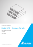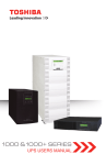
1
ITEM 1 DELTA P/N SUPPLIER P/N 5011361602 NOTES *1 NOTES : *1 MANUAL OPERATION GES302R200035 ESI ENG *2 MUST MEET DELTA'S GENERAL SPEC. :10000-0162 *3 封面部分:長:210mm±2 寬:150±2 材質:120P特銅紙 表面處理: 無 *4 內文部份:長:210mm±2 寬:150±2 材質:70P模造紙 印刷色數: 1色 *5 字體印刷顏色: 黑色 裝訂方式: 騎馬釘 *6 備註:天地至少留10mm 附件一共31頁 REV. Description Date Drawn Designed 00 RELEASED & ISSUED 7/18/2008 7/18/2008 7/18/2008 01 封面修改,不影響採購進料 7/22/2008 7/22/2008 7/22/2008 02 CHAPTER 6 TROUBLESHOOTING 增加內容 9/22/2008 9/22/2008 9/22/2008 03 更換 Page 12, 14~16, 25 圖片 9/23/2008 9/23/2008 9/23/2008 04 修改 TECHNICAL SPECIFICATIONS 內容 01/16/2009 01/16/2009 01/16/2009 台達電子工業股份有限公司 DELTA ELECTRONICS, INC. THESE DRAWINGS AND SPECIFICATIONS ARE THE PROPERTY OF DELTA ELECTRONICS , INC. AND SHALL NOT BE REPRODUCED OR USED AS THE BASIS FOR THE MANUFACTURE OR SELL OF APPARATUSES OR DEVICES WITHOUT PERMISSION. File Name : FR1R00.XLS DESCRIPTION : Electronic Mechanical 5011361602 Approved DDCCChungLi Document is Released 2009.01.22 15:59:50 +08'00' SUPPLIER : SANLI MANUAL DRAWING NO. : Safety REV. 04 SHEET 1 TO END GAIA series 1- 3 KVA USER MANUAL ONLINE GA1000R GA2000R GA3000R Uninterruptible Power Supply 1 CONTENTS IMPORTANT SAFETY INSTRUCTIONS ................................................................................ 2 CHAPTER 1 INTRODUCTION ............................................................................................. 5 1-1 THEORY OF OPERATION..................................................................................................... 5 1-2 FEATURE ......................................................................................................................... 7 1-3 ANNOTATION AND SYMBOL ................................................................................................. 9 CHAPTER 2 OPERATION ................................................................................................. 10 2-1 OPERATION PANEL ......................................................................................................... 10 CHAPTER 3 INSTALLATION............................................................................................. 14 3-1 MOUNTING..................................................................................................................... 14 3-2 CONNECTING THE BATTERY BANK ..................................................................................... 15 3-3 CONNECTING THE RS-232/DRY CONTACT ........................................................................ 16 3-4 CONNECTING THE LOAD .................................................................................................. 16 3-5 CONNECTING TO UTILITY POWER ...................................................................................... 17 3-6 TURNING “ON” THE UPS ................................................................................................ 17 3-7 COLD START WHEN UTILITY POWER IS NOT PRESENT .......................................................... 17 3-8 UPS SELF-TEST ............................................................................................................. 17 3-9 SILENCE FUNCTION......................................................................................................... 18 3-10 TURNING “OFF” THE UPS............................................................................................. 18 3-11 IF CERTAIN ABNORMAL CONDITION OCCURS, THE UPS WILL SEND THE FOLLOWING MESSAGES: ........................................................................................................................................... 18 3-12 DE-RATING POWER....................................................................................................... 19 3-13 UPS INTERNAL FAULT ................................................................................................... 20 CHAPTER 4 COMMUNICATION INTERFACE .................................................................. 21 4-1 RS232/ USB................................................................................................................. 22 4-2 DRY CONTACT ............................................................................................................... 23 4-3 SNMP CARD ............................................................................................................... 24 CHAPTER 5 BATTERY REPLACEMENT.......................................................................... 25 5-1 BATTERY REPLACEMENT (SEE FIGURE 5-1)...................................................................... 25 CHAPTER 6 TROUBLESHOOTING .................................................................................. 26 TECHNICAL SPECIFICATIONS........................................................................................... 29 1 2 IMPORTANT SAFETY INSTRUCTIONS Save These Instructions! This manual contains important instructions for our UPS that should be followed during installation and maintenance of the UPS and batteries. The UPS has an internal battery supply. The nominal rating voltage of battery supply is 24V, 48V, 72V for 1KVA, 2KVA and 3KVA UPS individually no matter what model of the 1KVA, 2KVA and 3KVA UPS. To reduce the risk of electric shock, install this UPS in a temperature and humidity controlled indoor area free of conductive contaminants. Ambient temperature must not exceed 40°C (104°F) The AC output of the UPS need a disconnect switch such as a breaker which has to be provided by others. The over-current protection for the output AC circuit has to be provided by others. All of our UPS have an electronic protection of AC output short circuit. Servicing of batteries should be performed or supervised by personnel who are knowledgeable about batteries and the required precautions. Keep unauthorized personnel away from batteries. When replacing batteries, replace with the same number of the: LC-R129 (PANASONIC), REW45-12 (YUASA), HR9-12 (BB), and HR1234F2 (CSB). CAUTION! CAUTION! Do not open or mutilate the battery or batteries. Released electrolyte is harmful to the skin and eyes. It may be toxic. CAUTION! A battery can present a risk of electrical shock and high short circuit current. The following precautions should be observed when working on batteries: Remove watches, rings, or other metal objects. Use tools with insulated handles. Wear rubber gloves and boots. Do not lay tools or metal parts on top of batteries. Do not dispose of battery or batteries in fire. The battery may explode. 2 3 Disconnect charging source prior to connecting or disconnecting battery terminals. Determine if the battery is inadvertently grounded. If inadvertently grounded, remove source of ground. Contact with any part of a grounded battery can result in electrical shock. The likelihood of such shock will be reduced if such grounds are removed during installation and maintenance (applicable to UPS and a remote battery supply not having a grounded supply circuit). This UPS contains batteries, which are potentially hazardous to user, even when the UPS is not connected to the utility power. [1KVA MODEL] Federal Communications Commission Interference Statement This equipment has been tested and found to comply with the limits for a Class B digital device, pursuant to Part 15 of the FCC Rules. These limits are designed to provide reasonable protection against harmful interference in a residential installation. This equipment generates, uses and can radiate radio frequency energy and, if not installed and used in accordance with the instructions, may cause harmful interference to radio communications. However, there is no guarantee that interference will not occur in a particular installation. If this equipment does cause harmful interference to radio or television reception, which can be determined by turning the equipment off and on, the user is encouraged to try to correct the interference by one of the following measures: Reorient or relocate the receiving antenna. Increase the separation between the equipment and receiver. Connect the equipment into an outlet on a circuit different from that to which the receiver is connected. Consult the dealer or an experienced radio/TV technician for help. FCC Caution: To assure continued compliance, (example-use only shielded interface cables when connecting to computer or peripheral devices). Any changes or modifications not expressly approved by the party responsible for compliance could void the user’s authority to operate this equipment. This device complies with Part 15 of the FCC Rules. Operation is subject to the following two conditions: (1) this device may not cause harmful interference, and (2) this device must accept any interference received, including interference that may cause undesired operation. 3 4 [2, 3KVA MODELS] Federal Communications Commission Interference Statement This equipment has been tested and found to comply with the limits for a Class A digital device, pursuant to Part 15 of the FCC Rules. These limits are designed to provide reasonable protection against harmful interference when the equipment is operated in a commercial environment. This equipment generates, uses and can radiate radio frequency energy and, if not installed and used in accordance with the instructions manual, may cause harmful interference to radio communications. Operation of this equipment in a residential area is likely to cause harmful interference in which case the user will be required to correct the interference at his own expense. 4 5 CHAPTER 1 INTRODUCTION 1-1 Theory of operation The main topology of the UPS consists of bypass path, AC-DC converter, DC-AC inverter, battery charger, DC-DC converter, control circuit and detection circuit. Moreover, the intelligent power management software is also optional. The function and efficiency are superior to the traditional UPS. BYPASS PFC C ontrol C ircuit LED B oard C ontrol Board To C ontrol Board To Auxiliary Pow er R elay Breaker AC I/P EM I Filter BYPASS R ELAY AC -D C D ouble Booster H alf-bridge D C -AC Inverter AC O /P Battery Bank C harger D C -D C C onverter To C ontrol B oard To C ontrol Board To External Battery Bank Auxiliary P ow er Figure 1-1 Hardware block diagram of the UPS The UPS operation is described as below: When the utility power is applied into the UPS, it was divided into two ways after going through the breaker and EMI filter. One way is connected to AC-DC converter which converts the utility AC power into a DC voltage which is called DC-BUS voltage then divides into two paths. One path goes to charger which converts the DC-BUS voltage into a proper DC voltage to charge the UPS battery. The other path goes into DC-AC half bridge inverter. The other way works as a bypass path. The bypass relay near the output will choose either the bypass path or inverter output. In general, the UPS will internally do the self-diagnosis. If there is no problem, the bypass relay will choose the inverter output. This is so called “ON-LINE mode”. 5 6 In case the utility power fail, the AC-DC converter and charger will be off duty. The DC-DC converter works and converts the battery voltage into DC-BUS voltage. The DC-AC inverter converts the DC-BUS voltage into AC voltage. This is so called “ON-BATTERY mode”. The auxiliary power circuit supplies the designated power to all the control circuits. Because the DC-AC inverter is always working, the DC-DC converter can work rapidly and replace the AC-DC converter while the utility power fails. Furthermore, the bypass relay continuously keeps in the position of inverter output to supply the regulated power for the load. There is no power failure to loading equipment. 6 7 1-2 Feature The UPS, available in 1KVA, 2KVA and 3KVA, is an advanced on-line UPS providing reliable and consistent sine-wave quality power to vital equipment. It supports personal computers, networks, servers, telecommunication equipment and a variety of other facilities. With its outstanding protection features, the unit keeps your applications safe and running smoothly at all times. High power density Other than traditional UPS adopting 0.7 output power factor, the UPS uses the latest technology and highest quality components giving output power factor up to 0.8. Compared to other UPS (1000VA/800W), these UPS series boosts a 12% more output power. This UPS with its compact size, generates higher power density thus giving convenience to the users. Moreover, through the use of advanced technology, the UPS efficiency increases to more than 87%. Compared with other traditional UPS with only 80 to 85% efficiency, this UPS produces greater electric power efficiency at less electric costs. PFC (Power Factor Correction) With this function, the investment in the capacity of circuit breakers can be reduced, specially it will be highly regarded as an important feature in critical load applications. Complete Protection On-line double conversion design, pure sine wave output and zero transfer time provide best protection. With a built-in surge, spike and line noise protection, the UPS prevents destructive hardware damage and extends system life. The EMI/RFI filtering design prevents electrical noise from affecting computer operation and data files. Besides, the UPS provides built-in Fax/Network cable (RJ11/RJ45) jacks protecting your hardware from surge, spikes and line-noise which travel along communication lines, therefore providing you a complete “back door” protection. Intelligent design Integrated with a microprocessor, the UPS is able to perform intelligent functions. The UPS triggers over-voltage protection function and transfers to “On- Battery mode” even when utility voltage exceeds 275V. In addition, the UPS can accept large voltage variation of 130V to 275V. Wide input voltage range means less battery power usage frequency and longer battery life span. Besides, programmable outlet design, suitable for power management, is also 7 8 included in this unit. Considerate design Battery start function allows startup of the UPS even when there is no AC line available. In addition, the UPS which was shut down by remote control during power line blackout will restart automatically when AC power recovers. Using our automatic frequency sensing function to match input and output frequency, users don't need to set either 50Hz or 60Hz. Other features, such as UPS self-diagnosis and flexible external battery pack, are also included. Green function design The operation in sleeping mode is designed to just keep charging which saves the energy a lot. User friendly interface The UPS provides a variety of functions which meet users’ needs. Users can instantly understand the status of the UPS via the informative LED display. Audible alarms, bar meters and status indicators, such as battery replace indication, UPS fault, line condition, overload etc. are simple and easy for user to understand. Moreover, users can simply reset the circuit breaker instead of having to replace a fuse in the event of output overload. Network Management Build-in communication interface port supporting RS232 and Dry contact protocols enhances the reliability and manageability of the UPS over all major operating systems, including Windows 95/ 98/ 2000/ NT/ XP/ Vista, Netware, UNIX, and others. Besides, the UPS also supports the Simple Network Management Protocol and Hyper Text Transfer Protocol via plugging a SNMP/HTTP adapter into the build-in SNMP slot. 8 9 1-3 Annotation and symbol The two signs shown on the manual indicating important instruction need to be followed. ! Read before Operation Maybe Dangerous/Follow Instructions Protective grounding terminal: A terminal which must be connected to earth ground prior to making any other connection to the equipment. This symbol indicates the word “phase”. ON TEST This symbol indicates the principal on/off switch is in the “ON” position. OFF This symbol indicates the principal on/off switch is in the “STAND-BY” position. 9 10 CHAPTER 2 OPERATION 2-1 Operation Panel OVERLOAD 100% FAULT ON TEST 75% 50% BYPASS OFF 25% LINE ONLINE LOAD BATT. ON BATT. BATT. LOW REPLACE BATT. UNINTERRUPTIBLE POWER SUPPLIES OVERLOAD B. 10 B. 5 100% B. 11 FAULT B. 1 BYPASS 75% A. 1 OFF A. 2 50% 25% B. 2 ON TEST LINE B. 3 B. 7 B. 4 ONLINE LOAD BATT. ON BATT. BATT. LOW REPLACE BATT. UNINTERRUPTIBLE POWER SUPPLIES Figure 2-1 Operation Panel 10 11 B. 6 B. 9 B. 8 Operation Panel A. Button: 1. ON/TEST Switch: The button is used for turning on the UPS, it can also perform the battery test function in “ON-LINE mode”. In “ON-BATTERY mode”, this button can turn off the buzzer for silence. 2. OFF Switch: The button is used for turning off UPS. B. LED Display Status: 1. Bypass: This LED indicates that the UPS is in “BYPASS mode”. 2. Line LED: This LED indicates the condition of input line. If the input voltage is too low, too high, or out of frequency, this LED will flash. When line is blackout, this LED will light off. 3. ON Line LED: This LED indicates that the UPS is running in “ON-LINE mode”. 4. ON Battery LED: This LED indicates the UPS is running in “ON-BATTERY mode” (backup mode), the internal batteries will supply the power. 5. Level LEDs: The four LEDs indicate that the current battery capacity in “ON-BATTERY mode” or the current load level of the UPS in “ON-LINE mode”. 6. Battery LED: When this LED lights up, “Level LEDs” will show the current battery capacity. 7. Load LED: When this LED lights up, “Level LEDs” will show the load level of the UPS. 8. Battery Low: This LED indicates that the UPS is in the “Battery Low” condition. 9. Battery Replace: After Battery test, This LED indicates that the batteries are weak and it is suggested to the users to replace the batteries. 10. Overload: This LED indicates that the load level exceeds the rating, after a limited period of time, the UPS will transfer to “BYPASS mode” and this LED will still light on to alarm the user. 11. Fault: This LED indicates that the UPS is fault. 11 12 Rear Panel The rear panel is explained as follows: (Please refer to Figure 2-2.1 and 2-2.2) 3 2 7 1 8 4 INPUT BREAKER LOAD 1 LOAD 2 24V DC 40A SNMP SLOT INPUT IN OUT SURGE PROTECTOR 5 REPO RS232 10 6 9 Figure 2-2.1 (1KVA Rear Panel) 2 7 4 1 8 INPUT BREAKER SNMP SLOT LOAD 1 LOAD 2 48V DC 40A INPUT 3 IN OUT SURGE PROTECTOR LOAD 3 1 5 REPO RS232 10 6 9 Figure 2-2.2 (2KVA & 3KVA Rear Panel) 1. OUTPUT RECEPTACLES: The UPS supplies AC power to the load. 2. I/P BREAKER: To prevent the UPS from damages caused by the high input current 3. INPUT SOCKET: AC input utility supplies power to the UPS via the socket. 4. SNMP SLOT: A SNMP adapter can be plugged in this port for managing the UPS on network. Please refer to section four for more detailed information. (Optional) 5. TVSS (Transient Voltage Surge Suppressor) (RJ-45/RJ-11 SURGE PROTECTOR): These connectors are used to prevent damages caused by surge, noise and spike traveling from the telephone or network line. 12 13 6. COMMUNICATION INTERFACE (RS-232/DRY CONTACT): The communication port is used to communicate PC and UPS. Please refer to section four for more detailed information. 7. Fan: DC fans for cooling purpose. 8. External Batteries Connector: Used for connecting external battery Bank to extend back up time. 9. USB: USB connector can be plugged in this port. The communication port is used to communicate PC and UPS. 10. EPO (RJ11/Emergency power OFF): When UPS is connected to RJ11 connector. It enables emergency Shutdown of UPS’s inverter. 13 14 CHAPTER 3 INSTALLATION Before unpacking the UPS, check the packing box. If there is any visible damage, contact your dealer at once. 1. Any individuals with previous training should operate this unit. 2. This unit should be installed by service personnel. 3-1 Mounting 3-1-1 Enclosure Mounting Install the mounting bracket. See Figure 3-1. Figure 3-1 UPS Mounting 3-1-2 Vertical Installation The UPS is rack mountable as well as standing alone. You can mount the UPS on the shelf, or you can erect the UPS with the supporting stands as Figure 3-2. Vertical Bracket Figure 3-2 Vertical Installation 14 15 3-2 Connecting the battery bank 1. Before installation, check the rating voltage of battery bank is suitable for the UPS. 2. When UPS is running for the first time, charge the UPS for at least 8 hours to ensure batteries inside are fully charged before operation. 3. Utilize the battery connection cable, be attached in battery bank package, packed with the battery bank and UPS show as Figure 3-3. INPUT BREAKER LOAD 1 LOAD 2 24V 40A LOT INPUT OUT IN SURGE PROTECTOR REPO RS232 ON DC BREAKER 24V 40AMAX. For 1KVA INPUT BREAKER SNMP SLOT LOAD 1 LOAD 2 72V 40A INPUT IN OUT SURGE PROTECTOR LOAD 3 REPO RS232 ON DC BREAKER 24V 40AMAX. For 2KVA & 3KVA Figure 3-3 UPS Connected to the External Battery Bank Notice: Normally, the life of a battery is 3~5 years. But extreme operating condition and environment may shorten its life-span. When UPS has not been used for a period of time, the batteries will discharge slightly. It is recommended to charge the UPS once every 3 months. Safety Requirement: In order to remove the battery power cord emergently, please plug in the power cord directly. Besides plugging in the battery power cord, the battery power cord needs to be fixed with the screws. 15 16 3-3 Connecting the RS-232/Dry contact Connect the interface signal cable between the RS-232/Dry contact port on the rear panel of UPS and COM1 or COM2 of computer if necessary (Show as Figure 3-4.1 and 3-4.2). Refer to section four for more information. Figure 3-4.1 UPS Connection for 1KVA: 1. Connect to RS232 Port. 2. Connect to PC. 3. AC input utility supplies power to the UPS. INPUT BREAKER LOAD 1 LOAD 2 24V DC 40A SNMP SLOT INPUT IN OUT SURGE PROTECTOR REPO RS232 Figure 3-4.2 UPS Connection for 2KVA or 3KVA: 1. Connect to RS232 Port. 2. Connect to PC. 3. AC input utility supplies power to the UPS. INPUT BREAKER SNMP SLOT LOAD 1 LOAD 2 72V DC 40A INPUT LOAD 3 IN OUT SURGE PROTECTOR REPO RS232 3-4 Connecting the load 1. Calculate power consumption of your loads to ensure that the overload condition will not happen. 2. Plug the power cord of the equipment into the output receptacles on the rear panel of the UPS. Caution: Do not connect a laser printer to the UPS. ! 16 17 3-5 Connecting to utility power AC input utility supplies power to the UPS. After that, the fan (in rear panel) will run and all LEDs will light for about 2-3 seconds. Users can check whether all LEDs are normal or not. The UPS is set in “STANDBY mode” initially. Meanwhile battery will be charged. (Shown as Figure 3-5) OVERLOAD 100% FAULT ON TEST 75% 50% BYPASS OFF 25% LINE ONLINE LOAD BATT . ON BATT. BATT. LOW REPLACE BATT. UNINTERRUPTIBLE POWER SUPPLIES Figure 3-5 Stand-By Mode 3-6 Turning “ON” the UPS When the utility power is acceptable for the UPS, line LED and load LED light on, you can normally turn on the UPS after pushing the [ On Test ] button and hold for 3 seconds until a short beep is heard. The bypass LED will extinguish after shortly light on. When the on-line LED lights on, the UPS is running in “ON-LINE mode”. (Shown as Figure 3-6) Note! When you hear the beep sound, please release the button. OVERLOAD 100 % FAULT ON TEST 75% 50% BYPASS OFF 25% LINE ONLINE LOAD BATT . ON BATT. BATT. LOW REPLACE BATT. UNINTERRUPTIBLE POWER SUPPLIES Figure 3-6 On-Line Mode 3-7 Cold start when utility power is not present Even when there is no utility power, you can still turn on the UPS. Just press the [ On Test ] button and hold for 3 seconds, the UPS will start up after you hear a short beep. The battery LED and on-battery LED will light on and the UPS runs in “ON-BATTERY mode”. (Shown as Figure 3-7) OVERLOAD 100 % FAULT ON TEST 75% 50% BYPASS OFF 25% LINE ONLINE LOAD BATT . ON BATT. BATT. LOW REPLACE BATT. UNINTERRUPTIBLE POWER SUPPLIES Figure 3-7 On Battery Mode 3-8 UPS self-test If press the [ On Test ] button when the UPS is in “ON-LINE mode”, it will make the UPS shift to “ON-BATTERY mode” and automatically perform a self-test for about 10 seconds. The self-test function will check the condition of the battery. After self-test is finished and test is O.K, the UPS will return to “ON- LINE mode”. 17 18 3-9 Silence function The buzzer can be turned “On” or “Off” by pressing the [ On Test ] button when the UPS is in “ON-BATTERY mode”. 3-10 Turning “OFF” the UPS Push the [ OFF ] button for turning off the UPS. When a short beep is heard, please release your press. After a few seconds the UPS will be off. The UPS will keep charging when UPS is in “STANDBY mode” even though the [ OFF ] button has been pressed. To fully turn off the UPS, it is advised to unplug the power cord. 3-11 If certain abnormal condition occurs, the UPS will send the following messages: “ON-BATTERY mode”: When the UPS is in “ON-BATTERY mode”, the on- battery LED will light on, buzzer beep half second every 2 seconds and then the UPS will start supplying power to load through batteries. (Shown as Figure 3-8) OVERLOAD 100% FAULT ON TEST 75 % 50 % BYPASS OFF 25 % LINE ONLINE LOAD BATT . ON BATT. BATT. LOW REPLACE BATT. UNINTERRUPTIBLE POWER SUPPLIES Figure 3-8 On-Battery Mode OVERLOAD: If the load exceeds the UPS rating, after a limited period, the overload LED will light on and buzzer continuous beeping to alarm the user. The user should unplug some uncritical loads to release the overload condition. (Shown as Figure 3-9) OVERLOAD 100% FAULT ON TEST 75 % 50 % BYPASS OFF 25 % LINE ONLINE LOAD BATT . ON BATT. BATT. LOW REPLACE BATT. UNINTERRUPTIBLE POWER SUPPLIES Figure 3-9 Overload and UPS turn into Bypass 18 19 BATTERY REPLACE: This LED function is to alert user that the batteries should be replaced. When the microprocessor in the UPS detects a battery fault, the buzzer beep 0.1 second every 2 seconds. (Shown as Figure 3-10) OVERLOAD 100% FAULT ON TEST 75 % 50 % BYPASS OFF 25 % LINE ONLINE LOAD BATT . ON BATT. BATT. LOW REPLACE BATT. UNINTERRUPTIBLE POWER SUPPLIES Figure 3-10 Battery Replace BATTERY LOW: This function is to inform user the remaining power capacity of the batteries. When batteries reach a low level condition, the UPS alarm will beep half second every 1.5 seconds until running out of battery capacity. (Shown as Figure 3-11) OVERLOAD 100% FAULT ON TEST 75% 50% BYPASS OFF 25% LINE ONLINE BATT . ON BATT. BATT. LOW REPLACE BATT. LOAD UNINTERRUPTIBLE POWER SUPPLIES Figure 3-11 Battery Low SHORT CIRCUIT: When the output of the UPS shorts in “ON-LINE mode” or “ON-BATTERY mode”, the UPS will shut down (without output voltage). As soon as the short circuit is happened, the fault LED will light on and the UPS alarm will sound continuously. When remove short circuit, the UPS output will recover. If short circuit is happened in “BYPASS mode”, the UPS will protect itself by tripping the input breaker and shut down. (Shown as Figure 3-12) OVERLOAD 100% FAULT ON TEST 75 % 50% BYPASS OFF 25% LINE ONLINE LOAD BATT . ON BATT. BATT. LOW REPLACE BATT. UNINTERRUPTIBLE POWER SUPPLIES Figure 3-12 Short Circuit 3-12 De-rating Power In the range of 130Vac to 160Vac, the UPS load capacity will decrease. This function provides a wider operating power voltage range. 19 20 3-13 UPS internal fault If the following conditions occur, the UPS fails. At this time the UPS will transfer to “BYPASS mode”. The bypass LED and fault LED will light on and alarm continuously. If utility is too low or too high the UPS output will be disabled. For fault messages, please refer to the troubleshooting (section 6) of this manual. 9 When the UPS inner components overheat, the UPS will protect itself by thermal switches. This status is so-called “O.T.P”. Show as Figure 3-13. When the UPS fan is failure. It is show as Figure 3-14. 9 When under (or over) voltage is happened in the UPS output. This kind of fault will be detected by the microprocessor in the UPS and is so-called “U.V.P” (“O.V.P”). Show as Figure 3-15, 3-16. 9 When under (or over) bus voltage is happened in the UPS and is so-called “Bus U.V.P” (“Bus O.V.P”). Show as Figure 3-17, 3-18. OVERLOAD OVERLOAD 100% FAULT ON TEST 75% 50% BYPASS FAULT ON TEST BATT. ON BATT. BATT. LOW REPLACE BATT. UNINTERRUPTIBLE POWER SUPPLIES ON TEST 75% 50% BYPASS OFF 25% OFF 25% LINE LOAD FAULT 50% OFF 25% 100% 75% BYPASS LINE ONLINE OVERLOAD 100% LINE ONLINE BATT. ON BATT. BATT. LOW REPLACE BATT. LOAD UNINTERRUPTIBLE POWER SUPPLIES ONLINE LOAD BATT. ON BATT. BATT. LOW REPLACE BATT. UNINTERRUPTIBLE POWER SUPPLIES Figure 3-13 (O.T.P.) Figure 3-14 (Fan Fail) Figure 3-15 (Inverter U.V.P.) Figure 3-16 Figure 3-17 Figure 3-17 (Inverter O.V.P.) (DC BUS U.V.P.) (DC BUS O.V.P.) 20 21 CHAPTER 4 COMMUNICATION INTERFACE The UPS provides RS-232 and Dry contact protocols in one D-sub 9 connector. Using proper UPS management software and cable, the UPS can be managed in LAN/ Intranet/ Internet environment. The pin assignment of the D-sub 9 connector is defined as follows: ASSIGNMENT DESCRIPTION PIN RS-232 Dry Contact 1 Low battery (Open collector) 2 UPS TxD (typical RS-232 level) 3 UPS RxD (typical RS-232 level) 4 Reserved for PNP 5 GND GND 6 Reserved for PNP Reserved 7 Reserved for PNP Reserved 8 Remote Shutdown (5~12V) Utility Fail (Open collector) 9 Open Collector 6 1 7 2 8 3 9 4 5 Figure 4-1 Pin Assignment GND Figure 4-2 Open Collector Circuit Maximum voltage and current on pin 1, 8 is 30VDC, 10mA. 21 22 4-1 RS232/ USB The RS232/USB communication port provides the following functions: 1. Monitoring charger status 2. Monitoring battery status and condition 3. Monitoring inverter status 4. Monitoring UPS status 5. Monitoring the utility power status 6. Providing the power switch function for computer to turn on/off the utility power on schedule for power saving 7. Adjustable Transfer voltage HARDWARE: BAUD RATE---------------- 2400 bps DATA LENGTH------------- 8 bits STOP BIT-------------------- 1 bit PARITY----------------------- NONE CABLING: Standard D-sub 9 cable (UPS side: male, PC side: female) 22 23 4-2 Dry Contact Its major functions normally some or all of following: 1. To broadcast a warning when power fails. 2. To close the files before the battery is exhausted. 3. To turn off the UPS via computers. Pin1 The pin is normally open. When battery low, pin1 and pin5 are connected via photo coupler. Pin3 On Battery mode, the UPS will shut down when a high level voltage (5~12V) sustained for at least 3.8 seconds is applied. Pin5 Signal ground. Pin6, 7 Reserved. Pin8 The pin is normally open. When utility fails, pin8 and pin5 are connected via photo coupler. Cabling: The users must use the special cable. The connection is described as follows: PC (female) UPS (male) Pin1------------------Pin1 (battery Low) Pin3------------------Pin5 (GND) Pin4------------------Pin3 (Shutdown) Pin7------------------Pin6 Pin7------------------Pin7 Pin8------------------Pin8 (AC Fail) The communication port on the rear panel of the UPS may be connected to a computer. This port allows the computer to monitor the UPS and control the operation of the UPS in some cases. Some computers may have a special connector to link this communication port, or require a special plug-in card, or need special UPS monitoring software. Contact your dealer for details of different interface kits. Caution: Every time when you connect your UPS and computer, please make sure the utility exists. 23 24 4-3 SNMP CARD 1. SNMP (Simple Network Management Protocol) is the most popular protocol in the network. Via NMS (Network Management Station) can detect the status of all facilities in the network. 2. On the rear panel of UPS built-in a SNMP slot (Please refer to Figure 2-2 ), this optional interface unit can integrate UPS into the network and then you can easily monitor the UPS status. Once you install SNMP card in the UPS, you can’t get any information from UPS via RS232. i.e. 3. The SNMP card also supports SHTTP protocol, you can use browser Microsoft IE or Netscape Communicator to monitor or conFigure UPS. Besides, SNMP card supports Telnet and FTP for remote monitoring and firmware upgrading. Specification: Auto detecting 10/100MNetwork speed. Supporting protocol: TCP/IP, UDP, HTTP, ICMP, ARP, TELNET, BOOTP, DHCP, FTP and SNMPv1. Remote firmware upgradeable and configurable. Web server built-in, allow monitoring/controlling UPS via browser. VT100 terminal mode or Telnet to configure SNMP. Function: Schedule: Shutdown/Restart UPS, testing and control outlets. Testing: Scheduled testing battery can insure the UPS can work normally during power failure. Event log: Auto-record the power event. Historical records: Keep records of UPS status in specified interval. Event handling: configure special action for each power event to meet your requirement. On/ Off UPS: setup the power on/off timer. Outlet control: configure UPS outlets. 24 25 CHAPTER 5 BATTERY REPLACEMENT Servicing of batteries should be performed or supervised by personnel knowledgeable of batteries and the required precautions. Keep unauthorized personnel away from batteries. 5-1 Battery Replacement (See Figure 5-1) 1 Remove front panel. 2 Unscrew four bolts of the battery. Compartment. 3 Unplug battery connectors. 4 Unscrew two bolts . 5 Pull the battery set out and renew it. 6 Assemble UPS by reverse procedure. Step 1 Step 2 Step 3 Step 4 Figure 5-1 Battery Replacement 25 26 CHAPTER 6 TROUBLESHOOTING Problem Possible Cause Solution ON/ TEST button is not pushed. Press the ON/ TEST button to turn on the UPS. (Refer section 3 to turn on the UPS.) Battery low shutdown and utility is absent. Waiting for line recovery. UPS fault. Call for qualified service personnel if above actions do not solve the problem. UPS is not turned on. (No alarm, No LED 1. Reduce some loads The rear panel input circuit lights) connected to the UPS. breaker is tripped. (Button is 2. Reset the circuit tripped out) breaker. (Push button in) Batteries inside the UPS are Recharge the batteries for at not fully charged. least 8 hours. UPS is overloaded. UPS does not provide expected back-up time. Batteries are weak. Remove some unnecessary loads. Batteries weak faster when used often or operating at higher temperature. If the battery is near the end of its life, call for service personnel. Replace the battery even if the Replace Battery LED does not light. Charger fault or other reason. Call for service. 1. Recharge the batteries for at least 8 hours. 2. If problem remains Call for service personnel to, replace the batteries. “REPLACE BATTERY” Weak batteries. LED lights on. 26 27 Problem PC-UPS communication does not work properly. UPS operates on battery even though the line is in normal operating condition. UPS over temperature. Possible Cause Solution Incorrect transmission speed. Re-test after using another different transmission speed. Refer to communication interface (Section 3-4) of this Incorrect RS-232 connection. manual Re-connect the UPS with COM1 / COM2 on PC again. Incorrect USB connection. Re-connect the UPS with USB on PC again. No incoming utility. Check input power connection. The rear panel input circuit 1. Reduce some loads breaker is tripped. (Button is connected to the UPS. out). 2. Reset the circuit breaker. (Push button in) Very high, low or distorted utility voltage. Have qualified electrician check the input voltage. The exhaust fans and ventilation grills may be obstructed. Choose a well-ventilated area to position your UPS to allow adequate dissipation of heat. The environment temperature exceeds 40oC (104oF). Position your UPS in cooler area. “FAULT”LED lights on, UPS failure. alarm beeps Call fore service engineer. “OVERLOAD” LED lights on and buzzer beeps continuously. Overloaded. Remove some uncritical load. UPS O.T.P. Warning On-Line mode: Remove the The components used inside utility. the UPS overheat or wind channel block. Backup mode: Press the OFF key to turn off the UPS. 27 28 FAULT MESSAGE Following information indicates various symptoms. Use this information to determine what factors cause the problem. 1. Alarm will sound to alert user that the UPS requires attention. 2. One or more additional load/battery level LED indicators will illuminate to provide a diagnostic aid to the operator, described as below (Show as Figure. 6-1): Output temperature protect Fault LED light flash Output over voltage protect 50% LED light on Output under voltage protect 50% LED light flash Bus over voltage protect 25% LED light on Bus under voltage protect 25% LED light flash OVERLOAD OVERLOAD 100% 100% FAULT ON TEST 75% FAULT 50% BYPASS OFF OFF 25 % LINE ONLINE 50 % BYPASS 25% ON TEST 75 % LINE LOAD UNINTERRUPTIBLE POWER SUPPLIES BATT . ON BATT. BATT. LOW REPLACE BATT. ONLINE LOAD UNINTERRUPTIBLE POWER SUPPLIES Figure 6-1 (Fault) BATT . ON BATT. BATT. LOW REPLACE BATT. Figure 6-2 (Fault) In case that failure is happened and utility is too low or too high, the UPS output will disable and the bypass and line LED will flash. Show as Figure. 6-2 If problem continues, contact your local dealer. 28 29 TECHNICAL SPECIFICATIONS Model Capacity INPUT Output Outlet Battery Interface Environment Safety Approval Others Appearance 2KVA 3KVA 2KVA/1600W 3KVA/2100W Rated Voltage 200V, 208V, 220V, 230V, 240V Voltage Range 160V∼275V (Full Load); 130V~160V (70% to 100% Load Linearly De-rating) Frequency 50Hz/60Hz (±5 Hz) Power Factor ≥0.97 Voltage 200V, 208V, 220V, 230V (default), 240V Frequency 50 (default)/60Hz Voltage Regulation +2% Frequency Accuracy +0.05 Hz Wave Form Pure Sine Wave Transient Response +10% (10%∼90% Linear Load) THD ≤3%(Linear Load); ≤6%(Computer Load) Overload Capacity 105%-125% for 3mins; 125%-150% for 30secs; >150% for 0.5sec Crest Factor 3:1 Efficiency (AC-AC) ≥ 87% Receptacle IEC320 C13×3×2 IEC320 C13×3×2 + IEC320 C19×1 IEC320 C13×3×2 + IEC320 C19×1 Battery Voltage 24 V 48V 72V Battery Type (Lead acid) 12V/ 8.5Ah Back-up Time (Typical) 3.5mins (800W) 4mins (1600W) 5mins (2100W) Recharge Time 6 Hours After Complete Discharge to Recover 80% Transfer Time Transfer Time LED 1KVA 1KVA/800W Zero LED Status On-line、Bypass、On-battery、Overload、Battery Low、Fault、Battery Replace、Battery Level、Load Level Alarm Buzzer DB9 RS232/Dry Contact SNMP Slot Internal USB USB Port Noise (At 1 Meter) 45dBA 50dBA 60dBA Operating Temperature 0~40℃ Humidity 5%~--95% (Non-Condensing) Safety CE EMC EN62040-2 FCC CLASS B Lightning IEEE 62.41 Category A Battery Start Yes Extended Battery Bank Yes (Optional with Long Time) Long Time Model Yes (Optional) Dimension (W×D×H) 440x335x89 /mm 17.3x13.2x3.5 / inch 440x432x89 /mm 17.3x17x3.5 /inch 440x610x89 /mm 17.3x24x3.5 /inch Weight 13.0 kg / 28.7 lb 21.0 kg / 46.3 lb 31.0 kg / 68.3 lb EN62040-2 FCC CLASS A All specifications are subject to change without prior notice. 29 30 31