1
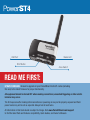
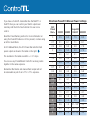
MAKE IT POSSIBLE™
®
Quick Guide
Receiver with
for Elinchrom
Please read this Quick Guide thoroughly before operating. Also, review
the product manuals for your camera, flash systems, and other
PocketWizard radios.
This PocketWizard radio runs on powerful software called
ControlTL® - Control The Light. It can be configured for your specific
needs using the PocketWizard Utility which can be downloaded at:
www.PocketWizard.com/support/downloads
The PowerST4 for Elinchrom requires a PocketWizard transmitting radio
and a compatible Elinchrom RX flash:
• Style 300RX, 600RX, 1200RX
• Digital 1200RX, Digital 2400RX
• Ranger RX, Ranger RX Speed (S), Ranger RX Speed AS
NOTE: Ranger models require Elinchrom’s EL 19374 - EL-Skyport Transceiver RX Adapter
The PowerST4 requires no batteries. It is powered from the remote port of your
Elinchrom RX flash.
USB Port
Status LED
TEST Button
Zone Switch
READ ME FIRST:
UPDATE FIRMWARE: Be sure to upgrade all your PocketWizard ControlTL radios (including
this one) to the latest firmware for proper functionality.
All equipment should be turned OFF when making connections; unwanted triggering or other erratic
behavior may occur.
The first exposure after making initial connections or powering on may not be properly exposed and flash
power levels may not be set as expected. Always test at least twice.
All information in this Quick Guide is subject to change. Visit www.PocketWizard.com/support
to find the latest flash and features compatibility, Quick Guides, and Owner’s Manuals.
To use your PowerST4:
1. Connect the PowerST4 to your RX flash pack
via the remote port, then power on the flash.
2. Select Zone A, B, or C with the Zone Switch
on your PowerST4. Default = A
3. Set up your PocketWizard transmitter and
take pictures normally.
Make sure all your radios are set to the same
PocketWizard channel. See the Learn Mode and
PocketWizard Utility sections for more information
on channels. Default = ControlTL 1
The Status LED blinks green every few seconds to
indicate normal operation. It will blink red in sync
with a trigger.
Momentarily pressing TEST/LEARN will
test trigger the flash. See the Learn Mode and Reset
sections for more information on those functions.
NOTE: The PowerST4 overrides settings you make directly on your flash. If you would like to change the beeper,
modeling light, or optical slave mode on your flash, just set those features on your flash before you turn on your
camera’s transmitter. You can also adjust these settings from your transmitter via the PocketWizard Utility. See that
section for more information.
If you would like the flash to simply trigger at the output power you set and not accept changes from the radio, follow
these steps: before turning on your transmitter, change your flash power level then press TEST on the PowerST4 and
wait for 3 amber blinks. Allow a few seconds between each step.
To allow the PowerST4 to control the flash features again, turn the flash OFF and back ON.
If you have a ControlTL transmitter like the MiniTT1 or
FlexTT5 then you can control your flash’s output level
remotely. Add the AC3 ZoneController for even more
control.
Read the PowerTracking section for more information on
using the PowerST4 when no AC3 is present, or when using
an AC3 in Auto Mode.
In AC3 Manual Mode, the AC3 Power Dial sets the flash
power output as shown in the table on the right.
The numbers in the table are within +/- 0.1 stops.
You can use any PocketWizard ControlTL receiving radios
together in the same exposure.
Remember that studio and manual flash output will not
be calculated as part of an E-TTL / i-TTL exposure.
Elinchrom PowerST4 Manual Power Settings
AC3
Power
Dial =
300RX
600RX
RangerRX/
1200RX* 2400RX
3
5.5
6.5
7.5
8.5
2.7
5.1
6.1
7.1
8.1
2.3
4.8
5.8
6.8
7.8
2
4.5
5.5
6.5
7.5
1.7
4.1
5.1
6.1
7.1
1.3
3.8
4.8
5.8
6.8
1
3.5
4.5
5.5
6.5
0.7
3.1
4.1
5.1
6.1
0.3
2.8
3.8
4.8
5.8
0
2.5
3.5
4.5
5.5
0.3
2.1
3.1
4.1
5.1
0.7
1.8
2.8
3.8
4.8
1
1.5
2.5
3.5
4.5
1.3
1.1
2.1
3.1
4.1
1.7
0.8
1.8
2.8
3.8
2
0.5
1.5
2.5
3.5
2.3
0.5
1.5
2.1 / 2.5*
3.5
2.7
0.5
1.5
1.8 / 2.5*
3.5
3
0.5
1.5
1.5 / 2.5*
3.5
PowerTracking
PowerTracking allows you to adjust your remote studio flash’s output power via the
camera’s FEC, ISO and aperture controls.
PowerTracking happens automatically when you have a MiniTT1 or FlexTT5 on
a Canon or Nikon camera and you are controlling a compatible studio flash with a
PowerST4 connected.
Center Point: The center point for PowerTracking is 3 stops down from your flash’s
maximum output power. All PowerTracking adjustments are based on this center point.
For example, if your flash’s maximum output power is 6.5, then the center point is 3.5.
PowerTracking with your camera’s controls: If there is no AC3 ZoneController on your transmitter, flash output
power on your remote studio flash will track up and down with FEC changes on your camera. Zero (0) on your
camera’s FEC control is the center point and equals 3 stops down from your flash’s maximum output setting.
Adjust FEC to raise or lower your flash power per the table on the previous page. See Camera FEC Range section
for more information.
Nikon: With no AC3 ZoneController on the transmitter, only the camera’s FEC control will
adjust flash power output level.
Canon: With no AC3 ZoneController on the transmitter, the camera’s ISO and FEC controls will
adjust flash power output level. The ISO in use for your first picture will be used as the center point for PowerTracking.
In the PocketWizard Utility for your transmitting ControlTL radio, this is called Full Manual and is the default operation
for PowerTracking when no AC3 ZoneController is in use. See below for settings in the PocketWizard Utility that allow
you to customize PowerTracking to also use your camera’s aperture controls for Canon and Nikon, or ISO controls
for Nikon.
PowerTracking with an AC3 ZoneController: When using an AC3 in A (Auto Mode), flash output power on your
remote flash will automatically track up and down with aperture, ISO, or FEC changes on your camera as well as the
Power Dial on the AC3. For example: If you narrow your aperture by 1 stop, flash power will increase by 1 stop to
keep the exposure the same.
Zero (0) on the AC3 Power Dial is centered on the aperture and ISO used for your first picture. For example, if your
first picture is at ISO 200 and F:8, then those values will be used as the center point for PowerTracking which is 3
stops down from your flash’s maximum output power.
Follow these steps to set the aperture and ISO values that will be used as the center point:
1.Turn on your camera and MiniTT1 or FlexTT5, but wait to press your shutter button or take any pictures.
2.Set the aperture and ISO you wish to use at the center point. Set the shutter speed as desired, however
changes to shutter speed will not affect PowerTracking.
3.Press the shutter button to take a picture. The center point is now set.
4.Adjust your camera’s ISO, aperture, or FEC to control flash output from the camera automatically
via PowerTracking.
To change the values used for the center point, turn off your transmitter then turn it back on and follow these
steps again.
Set the AC3 zone to Manual Mode to turn off PowerTracking.
Center on ISO & Aperture with First Shot is the default operation. For more information, see the PocketWizard Utility
section on adjusting this setting via the PowerTracking Tab for your transmitter.
IMPORTANT NOTE: Shooting in Shutter Priority/Tv, Program, Full Auto, or shooting quickly or making rapid exposure
changes is not recommended. The flash values may change rapidly and your remote flash may not be able to keep
up. Honor your flash’s ready wait time or “dump” as necessary.
FEC NOTE: Flash Exposure Compensation (FEC) can be set in many places and all values are added together.
FEC can be set:
•On the Power Dials of the AC3 ZoneController
•On the camera for all zones except AC3 Manual zones
•For transmitting radios, the PocketWizard Utility can adjust the PowerTracking center point for ISO and
aperture which affects all zones
•For the PowerST4, the PocketWizard Utility can adjust FEC for the connected flash on the Exposure Tab
If the combined FEC settings are more or less than your flash’s capabilities, then the flash will operate at maximum
or minimum output accordingly.
CAMERA FEC RANGE: The center point for PowerTracking is 3 stops down from your flash’s maximum, so normally
+3 on your camera’s FEC would equal flash maximum power. If your camera has a maximum FEC of +2 stops, and
you want that setting to equal your flash’s maximum output, set Flash Exposure Compensation in your PowerST4
to +1.0. When you have made this setting, Zero (0) on your camera’s FEC will now be 2 stops down from flash
max instead of 3. If your camera’s highest FEC is +1, set this control to +2.0. You can use this control to align your
camera’s lowest FEC setting with your flash’s minimum power similarly.
See the Exposure Tab - Flash Exposure Compensation section below for more information.
PocketWizard Utility
Some settings require the PocketWizard Utility software and your ControlTL
radio connected to a computer via the Mini-USB port. Download the Utility at
www.PocketWizard.com/support
PowerST4 Receiver Utility settings:
Channel Tab
Set your receive channel to match your transmitter. If you are using a MiniTT1 or FlexTT5 as your transmitter,
make sure Use ControlTL for Receive Channel is checked. If you are using a Standard transmitter like the Plus II
or MultiMAX, uncheck this box. Default = ControlTL 1
Exposure Tab
Flash Exposure Compensation (FEC): Offsets exposure for the connected flash only. This setting can be used
as a simple FEC control for an individual flash, or it can be used to set flashes on the same zone to different power
outputs or to balance them. For example, you could use -1.0 to make a 600RX match the power of a 300RX. This
setting is cumulative with other FEC values set in the system. This control can also be used to adjust where the
PowerTracking center point aligns with your camera’s FEC control. See the FEC NOTE and CAMERA FEC RANGE
section for more information. Default = 0.0
Flash Tab
Flash Idle Time Out Mode/Delay: The modeling light will turn off after the set time if no triggers are received.
Uncheck the box to have the modeling light stay on. Default = Enabled at 600 seconds (10 minutes)
IMPORTANT: Make sure to press the Set Configuration button to save your settings.
FlexTT5 or MiniTT1 Transmitter settings that affect the use of a
PowerST4:
Modeling Tab
Modeling Light Control: Check this box to control modeling light behavior from the transmitter. Default = Enabled
Control Mode: Determines when the modeling light will go to its active setting. Set to Camera Wake to have the
modeling light go active when the camera’s shutter release is half-pressed. Set to AF-Assist to have the
modeling light go active only when the camera requests auto-focus assist. Default = Camera Wake
Modeling Light Autotrack: Enable this control for the modeling light level to track with the camera exposure
or AC3 Power Dial settings. Default = Enabled
Modeling Light Active XX%: Sets the active output level of the modeling light if Autotrack is not used.
Default = 100%
Modeling Light Sleep: Check this box to have the modeling light automatically go to a set output level after
a set time. If this box is unchecked, the modeling light will never sleep. Default = Enabled
Modeling Light Sleep XX%: Sets the output level of the modeling light when it sleeps. Default = 10%
Modeling Light Delay After Camera Sleeps: Sets the number of seconds after the camera sleeps (meters go
inactive) when the modeling light will go to its sleep value. Default = 30 seconds
PowerTracking Tab
Speedlite Control: Adjusts how Canon Speedlites will respond to the AC3 or ControlTL Transmitter with no AC3.
It does not affect the PowerST4. Default = Normal E-TTL
PowerTracking Control: Adjusts how ControlTL-capable remote studio flashes, like flashes connected to PowerST4
radios, respond to the AC3 in Auto Mode, or to a ControlTL Transmitter with no AC3. See the PowerTracking section
for information.
Full Manual (default): Turns off PowerTracking for aperture and ISO.
With an AC3 ZoneController on the transmitter, any zones set to Auto Mode will operate as Center on ISO & Aperture with First Shot (see below) when this control is set to Full Manual. AC3 Manual Mode can be used to adjust flash output power manually with an AC3.
Nikon: With no AC3 ZoneController on the transmitter, only the camera’s FEC control will
adjust flash power output level.
Canon: With no AC3 ZoneController on the transmitter, the camera’s ISO and FEC controls will
adjust flash power output level.
Center on ISO & Aperture with First Shot: The aperture and ISO as set on the camera for the first exposure after powering on the MiniTT1 or FlexTT5 will be used as the center values for PowerTracking. For example if your camera is set to ISO 100 and F:5.6 for its first exposure, then those exposure settings will equal 3 stops
down from your flash’s maximum output power. Adjustments to aperture, ISO, and FEC will adjust flash output power accordingly, as will adjusting the Power Dial on AC3 zone in Auto Mode. See the PowerTracking section
for more information.
Center on ISO & Aperture: Lets you control the exposure settings where the center for PowerTracking will begin. Adjust the drop-down boxes for the Aperture Center-On and and ISO Center-On values you want to use
as the center point (3 stops down from your flash’s maximum) for PowerTracking.
Center on Aperture Only: PowerTracking will only work with aperture changes. Set the desired aperture using the Aperture Center-On control. ISO changes will be ignored for PowerTracking.
Center on ISO Only: PowerTracking will only work with ISO changes. Set the desired ISO using the
ISO Center-On control. Aperture changes will be ignored for PowerTracking.
No Change (trigger only): Turns off PowerTracking and the Power Dials on the AC3 will not adjust the
power output of your remote flash. Use this setting if another AC3 is controlling the flash’s manual power
output, like when sharing flashes with another photographer and you want to use the exact same manual
flash output power.
AC9 Flash Exposure Compensation : This control is only for remote FlexTT5 radios with an
AC9 AlienBees Adapter in the hot shoe. It does not affect the PowerST4.
Flash Tab
Remote Beeper: Determines what setting the remote flash’s ready beeper will use the next time you half-press
the camera’s shutter release. Default = No Change on Wakeup.
Optical Trigger: Determines what setting the remote flash’s optical trigger will use the next time you half-press
the camera’s shutter release. Default = No Change On Wakeup.
See the NOTE on the To Use your PowerST4 page for more information on these settings.
The remaining settings on the Flash Tab do not apply to the PowerST4.
For other PocketWizard Utility settings, refer to the Owner’s Manuals for the MiniTT1, FlexTT5, AC3 ZoneController,
AC9 AlienBees Adapter, or other ControlTL radios or accessories.
Learn Mode
Your PowerST4 needs to be on the same channel as your transmitter. Channels can be set
via the PocketWizard Utility (recommended) or taught from any PocketWizard transmitter.
Learn Mode is not required for normal operation of the radios. See the PocketWizard
Utility section for more information on setting channels.
If you are using a ControlTL transmitter like the MiniTT1 or FlexTT5, and you want to have
your flash respond to power settings from the AC3 or perform PowerTracking, make sure
your PowerST4 learns a ControlTL channel. Standard Channels on the Plus II and MultiMAX
can be used for triggering only.
Follow the steps below to put your PowerST4 in Learn Mode.
IMPORTANT: Hold radios at least 2 feet apart when teaching/learning. Your flash may trigger during teach/learn.
1.Plug the PowerST4 radio into a compatible flash and turn it ON.
2.Press and hold TEST on the PowerST4 for several seconds until the Status LED blinks amber, then release TEST.
3. Immediately press and hold TEST on the teaching transmitting radio (MiniTT1, FlexTT5, MultiMAX or Plus II).
When the PowerST4 Status LED blinks green, the channel is learned:
• 1 green blink = Low Standard channel learned (1 through 16, including Plus 1 through 4)
• 2 green blinks = High Standard channel learned (MultiMAX 17 through 32)
• 3 green blinks = ControlTL channel learned for MiniTT1 or FlexTT5
Reset
RESET A / CHANNEL RESET:
To reset the learned channels back to the channels last set in the Utility, hold TEST as you power on the flash. The
Status LED blinks green twice to indicate a reset. Release TEST. Advanced features set via the Utility are retained.
RESET B / FACTORY DEFAULTS:
To reset all advanced features and channels to FACTORY DEFAULTS, press and hold TEST before you power on the
flash, continue to hold TEST as you power on the flash, and do not release TEST for about 10 seconds. When the
Status LED blinks green 4 times, release TEST.
PowerST4 PocketWizard Utility Defaults:
• Channel = ControlTL Channel 1
• Exposure Compensation = +/- 0.0
• Flash Idle Time Out Mode/Delay = Enabled at 600 Seconds (10 minutes)
PowerST4 radio information (RECEIVE ONLY):
340.00 – 354.00 MHz, US FCC/IC
433.42 – 434.42 MHz, CE
IMPORTANT: US FCC/Canada frequency radios are NOT compatible with CE frequency radios or Japan frequency
radios and vice versa. For more information on frequency, please go to: www.PocketWizard.com/wheretobuy/frequency
Temperature
Operating Temperature: Above -15° C (5° F) and below 50° C (120° F)
Storage Temperature: Above -30° C (-22° F) and below 85° C (185° F)
PocketWizard.com
Warranty:
This PocketWizard product is covered under a two-year limited manufacturer’s warranty. For warranty details, and to
register your product, please go to www.PocketWizard.com/support or contact your local PocketWizard Distributor.
Distributor contact information can also be found at www.PocketWizard.com. To receive a copy of the two-year limited
manufacturer’s warranty on this PocketWizard product, e-mail us at [email protected] or write to us at
LPA Design, Inc., 21 Gregory Drive, Suite 140, South Burlington, VT 05403, United States of America, Attn: Warranty.
© 2010 LPA Design, Inc. All rights reserved. Product features and specifications are subject to change without notice. PocketWizard, ControlTL, MiniTT1, FlexTT5,
PowerST4, AC3, AC9, HyperSync, Plus II and MultiMAX are either trademarks or registered trademarks of LPA Design, Inc. All other trademarks contained herein are
the property of their respective owners.
For more information on this product, including detailed features, specifications, etc., go to www.PocketWizard.com.
US Patent: 5,359,375 & US and other patents pending
LPF830 v1.0
MAKE IT POSSIBLE™