1
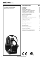
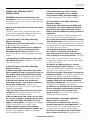
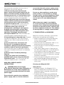
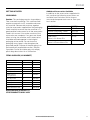
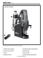
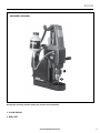
EVO42
42mm (1-5/8”)
MAGNETIC DRILLING SYSTEM
Instruction
Manual
Read instructions before operating this tool.
Guard omitted for illustrative purposes only.
This Instruction Manual was originally written in (UK) English.
www.evolutionsteel.com
TABLE OF CONTENTS
Original Instructions
Read instructions before operating this tool.
2
PAGE
Introduction
Guarantee
Technical Specification
Explanation of Labels and Symbols
Intended use of this Power Tool
Prohibited use of this Power Tool
03
03
04
05
05
05
SAFETY PRECAUTIONS
Electrical Safety
Outdoor Use
General Power Tool Safety Instructions
Specific Safety Instructions
06
06
07
08
GETTING STARTED
Unpacking
Machine Overview
Assembly and Preparation
Operating Instructions
11
12
14
15
MAINTENANCE
Environmental Protection
Service Parts Diagram
19
20
DECLARATION of CONFORMITY
22
www.evolutionsteel.com
EVO42
IMPORTANT INFORMATION
Please read these operating and safety
instructions carefully and completely.
For your own safety, if you are uncertain about
any aspect of using this equipment please access
the relevant Technical Helpline, the number of
which can be found on the Evolution Power
Tools website. We operate several Helplines
throughout our worldwide organization, but
Technical help is also available from your supplier.
WEB
www.evolutionpowertools.com/register
Congratulations on your purchase of an
Evolution Power Tools Machine. Please
complete your product registration ‘online’
as explained in the A5 online guarantee
registration leaflet included with this
machine. You can also scan the QR code
found on the A5 leaflet with a Smart
Phone. This will enable you to validate your
machine’s guarantee period via Evolutions
website by entering your details and thus
ensure prompt service if ever needed. We
sincerely thank you for selecting a product
from Evolution Power Tools.
EVOLUTION LIMITED GUARANTEE.
Evolution Power Tools reserves the right to
make improvements and modifications to the
product design without prior notice.
Please refer to the guarantee registration leaflet
and/or the packaging for details of the terms
and conditions of the guarantee.
Evolution Power Tools will, within the guarantee
period, and from the original date of purchase,
repair or replace any goods found to be defective
in materials or workmanship. This guarantee is
void if the tool being returned has been used
beyond the recommendations in the Instruction
Manual or if the machine has been damaged
by accident, neglect, or improper service. This
guarantee does not apply to machines and
/ or components which have been altered,
changed, or modified in any way, or subjected
to use beyond recommended capacities and
specifications. Electrical components are subject
to respective manufacturers’ warranties. All
goods returned defective shall be returned
prepaid freight to Evolution Power Tools.
Evolution Power Tools reserves the right to
optionally repair or replace it with the same or
equivalent item. There is no warranty – written
or verbal – for consumable accessories such as
(following list not exhaustive) blades, cutters,
drills, chisels or paddles etc. In no event shall
Evolution Power Tools be liable for loss or
damage resulting directly or indirectly from
the use of our merchandise or from any other
cause. Evolution Power Tools is not liable for any
costs incurred on such goods or consequential
damages. No officer, employee or agent of
Evolution Power Tools is authorized to make oral
representations of fitness or to waive any of the
foregoing terms of sale and none shall be
binding on Evolution Power Tools.
Questions relating to this limited guarantee
should be directed to the company’s head
office, or call the appropriate Helpline number.
SAFETY FIRST
Before attempting to operate this power tool,
the following basic safety precautions should
always be taken to reduce the risk of fire,
electric shock and personal injury:
• Read the Instruction Manual to understand the
safety instructions, application, limitation and
potential hazards associated with this power
tool.
• Only use genuine Evolution replacement
parts. The use of unauthorised parts may be
dangerous and could result in damage to the
machine and / or injury to the operator.
www.evolutionsteel.com
3
VIBRATION
TECHNICAL SPECIFICATION
Max Machine Height (mm):
670 (26-1/4”)
Min Machine Height (mm):
360 (14-1/8”)
Machine Width (mm):
180 (7”)
Machine Depth (mm):
300 (11-3/4”)
Machine Weight (Kg):
11.2 (25lbs)
Rack Stroke (mm):
130 (5-1/4”)
Rated Motor Power (Watts):
110 V/1200W (10A)
UK Voltage 1:
110V ~ 50/60Hz
UK Voltage 2:
230V ~ 50/60Hz
US Voltage 3:
120V ~ 50/60Hz
Rated Current (Amps) 240V:
5.4
IP Rating:
20
Spindle Speed –
470
No Load (min-1/rpm):
Number of Speeds:
Single
Power Cord Length (Mtr/Yr):
2.1m (2-1/3yr)
Insulation Class:
1
Max Annular Cutting Capacity
42 (1-5/8”)
(mm):
Max Cutting Depth (mm):
50 (2”)
Standard Twist Drill Capacity
13 (1/”2)
(mm):
Magnet Dimension (mm):
40 x 90 x 180
(1-3/4”x 3-3/4” x 7”)
Magnet Adhesion Stage 2
1300 (2850 lbs)
(Kg F):
Min Plate Thickness (mm):
10 (1/2”)
Sound Pressure Level LPA:
89.4dB(A) K=3dB(A)
Sound Power Level LWA:
102.4B(A) K=3dB(A)
Hand Arm Vibration an:
0.629m/s2 K=1.5m/
s2
Note: The vibration measurement was made
under standard conditions in accordance
with BS EN 61029 – 1:2009.
4
WARNING: When using this machine
the operator can be exposed to high
levels of vibration transmitted to the hand
and arm. It is possible that the operator could
develop “Vibration white finger disease”
(Raynaud syndrome). This condition can reduce
the sensitivity of the hand to temperature as
well as producing general numbness. Prolonged
or regular users of this machine should monitor
the condition of their hands and fingers closely.
If any of the symptoms become evident, seek
immediate medical advice.
• The measurement and assessment of human
exposure to hand-transmitted vibration in
the workplace is given in: BS EN ISO 53491:2001 and BS EN ISO 5349-2:2002
• Many factors can influence the actual vibration
level during operation e.g. the work surfaces
condition and orientation and the type and
condition of the machine being used. Before
each use, such factors should be assessed, and
where possible appropriate working practices
adopted. Managing these factors can help
reduce the effects of vibration:
Handling
• Handle the machine with care, allowing the
machine to do the work.
• Avoid using excessive physical effort on any
of the machines controls.
• Consider your security and stability, and the
orientation of the machine during use.
Work Surface
• Consider the work surface material;
its condition, density, strength,
rigidity and orientation.
WARNING: The vibration emission during
actual use of the power tool can differ
from the declared total value depending on
the ways in which the tool is used. The need
to identify safety measures and to protect the
operator are based on an estimation of exposure
in the actual conditions of use (taking account of
all parts of the operating cycle, such as the times
the tool is switched off, when it is running idle,
in addition to trigger time).
www.evolutionsteel.com
EVO42
SAFETY LABELS & SYMBOLS
INTENDED USE
WARNING: Do not operate machine if
warning and/or instruction labels are missing
or damaged. Contact Evolution Power Tools for
replacement labels.
• This power tool is intended to be used for
drilling holes with annular cutters and twist
drills, in an industrial environment.
• The machine is designed to be held onto
a magnetisable surface using its electromagnetic base.
• This power tool should be used in a weather
protected environment, and be used with
the accessories provided, or Evolution Power
Tools recommended accessories only.
• The power tool can be used vertically,
horizontally and inverted, provided the
magnetic adhesion and work environment
allow.
Note: All or some of the following symbols may
appear in the manual or on the product.
SYMBOL
MEANING
Eye protection should be worn
at all times when using this tool.
Hard Hat Head protection should be worn
at all times whilst using this tool,
to protect from overhead hazards
Ear protection / Ear defenders
should be worn at all times
whilst using this tool, this tool
exceed 85dB(A)
Electrical enclosure risk of electric shock.
Read and understand the
instruction manual - before
operating this tool.
Caution ! / Attention !
Instruction Manual
WEEE - Waste Electrical and
Electronic Equipment This
machine should be disposed of
as Electrical & Electronic Waste.
Fuse
WARNING: To prevent ingress of fluids
into the electrical system, cutting paste
should be used rather than cutting fluid when
using the machine in the inverted position.
PROHIBITED USES
• This power tool should never be used without
a ground or protective earth connection.
• This power tool should not be used in a
potentially explosive environment.
• This power tool should not be use in a wet
or humid environment where water could
be drawn into the power tools cooling and
ventilation system.
• If the power tool is used in the inverted or
horizontal position, cutting fluids should not
be used to prevent ingress of fluids into the
electrical system. Cutting paste should be
used instead.
• This power tool should never be positioned
on a work piece between the electrode and
ground of an arc type welder. Damage to the
machine will result as the welder will ground
through the power tools ground or earth cable.
• This power tool should not be used where
the voltage is abnormally lower than the
rated voltage, subject to voltage tolerances.
Check the power tool rating plate, check the
voltage available.
www.evolutionsteel.com
5
ELECTRICAL SAFETY - EU ONLY!
WARNING: Operating on a lower than
rated voltage will result in the electro
magnet being at reduced power and the
machine may become insecure whilst cutting.
CONNECTION OF THE MAINS PLUG - CLASS 1
MACHINES - EU ONLY
This product is fitted with the correct moulded
plug for the designated sales market. The
plug meets the requirements of international
standards, and must be connected to a supply
voltage that is equal to that stated on the
rating label. If the plug or mains supply lead are
damaged they must be replaced with a complete
assembly that is identical to the original. Adhere
to the requirements for mains electricity supply
connection that applies in your Country. If in
doubt consult a qualified electrician.
CONNECTION OF THE MAINS PLUG - CLASS 1
MACHINES - UK ONLY
Ensure that the outer insulation is gripped by
the cord grip and that the wires are not trapped
when replacing the plug cover.
A 13 amp (BS1362) fuse must be fitted in the
plug.
IF IN DOUBT CONSULT A QUALIFIED
ELECTRICIAN.
There are no user serviceable parts inside except
those referred to in the manual. Always refer
servicing to qualified service personnel. Never
remove any part of the casing unless qualified to
do so; this unit contains dangerous voltages.
OUTDOOR USE
Brown: Live (L)
Blue: Neutral (N)
Green and Yellow
or Green: Earth (E)
WARNING: For your protection, if this
tool is to be used outdoors, it should not
be exposed to rain or used in damp locations,
as water entering the power tool will increase
the risk of electric shock. Do not place the tool
on damp surfaces. For added protection use a
residual current device (R.C.D.) that will interrupt
the supply if the leakage current to earth
exceeds 30mA for 30ms. Always check the
operation of the residual current device (R.C.D.)
before using the machine.
THIS PRODUCT REQUIRES
A CONNECTION TO EARTH.
If an extension cable is required it must be a
suitable type for use outdoors and so labelled.
3 PIN PLUG MUST COMPLY TO BS1363/A.
FUSE MUST COMPLY TO BS1362.
These extension cords are rated for outdoor
use and reduce the risk of electric shock. The
manufacturers instructions should be followed
when using an extension cable.
IMPORTANT: The wires in the mains
lead fitted to this product are coloured in
accordance with the following code:
If for any reason the moulded 13 amp plug
fitted to this product requires replacement it
must be wired in accordance with the following
instructions:
Connect the Blue wire to the terminal marked
Neutral (N).
Connect the Brown wire to the terminal marked
Live (L).
Connect the Green and Yellow wire to the
terminal marked Earth E
6
DO NOT CONNECT THE BROWN (LIVE)
OR BLUE (NEUTRAL) TO THE EARTH PIN
MARKED E
ON THE 3 PIN PLUG.
Note: If the mains cable requires replacing it
must be replaced with an identical one and be
fitted by a qualified person.
(These General Power Tool Safety Instructions are
as specified in BS EN 60745-1:2009 & EN 610291:2009)
www.evolutionsteel.com
EVO42
POWER TOOL GENERAL SAFETY
INSTRUCTIONS
WARNING: Read all safety warnings and
instructions. Failure to follow the warnings and
instructions may result in electric shock, fire and/
or serious injury.
Save all warnings and instructions for future
reference.
The term “power tool” in the warnings refers
to your mains-operated (corded) power tool or
battery-operated (cordless) power tool.
1) General Power Tool Safety Warnings
[Work area safety]
a) Keep work area clean and well lit. Cluttered
or dark areas invite accidents.
b) Do not operate power tools in explosive
atmospheres, such as in the presence of
flammable liquids, gasses or dust. Power
tools create sparks which may ignite the dust or
fumes.
c) Keep children and bystanders away while
operating power tool. Distractions can cause
you to lose control.
2) General Power Tool Safety Warnings
[Electrical Safety]
a) Power tool plugs must match the outlet.
Never modify the plug in any way. Do not use
any adapter plugs with earthed (grounded)
power tools. Unmodified plugs and matching
outlets will reduce the risk of electric shock.
b) Avoid body contact with earthed or
grounded surfaces, such as pipes, radiators,
ranges and refrigerators. There is an
increased risk of electric shock if your body is
earthed or grounded.
c) Do not expose power tools to rain or wet
conditions. Water entering a power tool will
increase the risk of electric shock.
d) Do not abuse the cord. Never use the cord
for carrying, pulling or unplugging the power
tool. Keep cord away from heat, oil, sharp
edges or moving parts. Damaged or entangled
cords increase the risk of electric shock.
e) When operating a power tool outdoors,
use an extension cord suitable for outdoor use.
Use of a cord suitable for outdoor use reduces
the risk of electric shock.
f) If operating a power tool in a damp
location is unavoidable, use a residual
current device (RCD) protected supply. Use of
an RCD reduces the risk of electric shock.
3) General Power Tool Safety Warnings
[Personal Safety].
a) Stay alert, watch what you are doing and
use common sense when operating a power
tool. Do not use a power tool while you are
tired or under the influence of drugs, alcohol or
medication.
A moment of inattention while operating power
tools may result in serious personal injury.
b) Use personal protective equipment. Always
wear eye protection. Protective equipment such
as dust masks, non-skid safety shoes, hard hat or
hearing protection used for appropriate conditions
will reduce personal injuries.
c) Prevent unintentional starting. Ensure
the switch is in the off-position before
connecting to power source and or battery
pack, picking up or carrying the tool. Carrying
power tools with your finger on the switch or
energising the power tools that have the switch
on invites accidents.
d) Remove any adjusting key or wrench
before turning the power tool on. A wrench
or key left attached to a rotating part of a power
tool may result in personal injury .
e) Do not overreach. Keep proper footing and
balance at all times. This enables better control
of the power tool in unexpected situations.
f) Dress properly. Do not wear loose clothing or
jewellery. Keep your hair, clothing and gloves
away from moving parts. Loose clothes, jewellery
or long hair can be caught in moving parts.
g) If devices are provided for the connection
of dust extraction and collection facilities,
ensure that these are connected and
properly used. Use of dust collection can
reduce dust-related hazards.
4) General Power Tool Safety Warnings
[Power tool use and care].
a) Do not force the power tool. Use the
correct power tool for your application. The
correct power tool will do the job better and
safer at a rate for which it was designed.
b) Do not use the power tool if the switch
does not turn it on or off. Any power tool
www.evolutionsteel.com
7
that cannot be controlled with the switch is
dangerous and must be repaired.
c) Disconnect the power tool from the
power source and/or battery pack from the
power tool before making any adjustments,
changing accessories, or storing power tools.
Such preventative safety measures reduce the
risk of starting the power tool accidentally.
d) Store idle power tools out of the reach of
children and do not allow persons unfamiliar
with the power tool or these Instructions
to operate the power tool. Power tools are
dangerous in the hands of untrained users.
e) Maintain power tools. Check for
misalignment or binding of moving parts,
breakage of moving parts and any other
condition that may affect the power tool’s
operation. If damaged, have the power
tool repaired before use. Many accidents are
caused by poorly maintained power tools.
f) Keep cutting tools sharp and clean. Properly
maintained cutting tools with sharp cutting
edges are less likely to bind and are easier to
control.
g) Use the power tool, accessories and
tool bits etc. in accordance with these
instructions, taking into account the working
conditions and the work to be performed.
Use of the power tool for operations different
from those intended could result in a hazardous
situation.
5) General Power Tool Safety Warnings
[Service]
a) Have your power tool serviced by a
qualified repair person using only identical
replacement parts. This will ensure that the
safety of the power tool is maintained.
MAG DRILL SPECIFIC SAFETY
INSTRUCTIONS
Do not use other appliances on the same
power socket, as any variation in voltage
caused by other connected appliances could
result in the magnet deactivating. Always
use the tool on its own dedicated power
socket.
Where the power supply is provided by
an ‘onsite’ generator set, ensure that the
generator set is reliable and well maintained,
and that the fuel tank contains sufficient fuel
to allow completion of the task. The addition
of warning labels is strongly recommended.
1) TRANSPORTING and HANDLING.
Mag Drills are heavy machines, care must be
taken when transporting and handling.
• When transporting or moving the Mag Drill,
always use the carrying handle or other
carrying aids provided.
• Always ensure that the dovetail slide is in its
lowest position and locked in place.
• Do not transport or move the Mag Drill with a
cutter attached.
• If the coolant feed system is fitted, ensure
that the coolant feed tap is in the off position,
or the coolant system has been drained.
• If the Mag drill is to be transported in a vehicle
ensure that it is laid on its side and is secured
to prevent movement.
• Do not transport the Mag Drill with the mains
cord and plug dragging along the ground.
• Never carry or drag the machine using the
mains cord.
Carrying your Magnetic Drill
WARNING: Mains Power Supply
Security. Due to the nature of operation of
this machine, it is of the utmost importance to
ensure the security and continuity of the mains
power supply.
Ensure that this machine has a dedicated
power supply, and use a lock on device to
8
ensure that the mains power supply cannot
be interrupted or compromised accidentally.
Safety Advice
• Although compact, this Magnetic Drill is
heavy. To reduce the risk of back injury, get
competent help, if required, whenever you
have to lift the drill.
• To reduce the risk of back injury, hold the tool
close to your body when lifting. Bend your knees
so you can lift with your legs, not your back. Lift
by using the transportation/lifting handle.
www.evolutionsteel.com
EVO42
• Never carry the Magnetic Drill by the power
cord. Carrying the Magnetic Drill by the power
cord could cause damage to the insulation or
the wire connections resulting in electric shock
or fire.
• Before moving the Magnetic Drill tighten the
auxiliary slide locking screw to guard against
sudden unexpected movement.
• Lock the Drilling Head in its lowest position.
2) BEFORE USING THE MAGNETIC DRILL
• Check the mains cord and plug for any
damage. If damaged it must be replaced
before use.
• Check the complete machine for any signs of
damage. If the machine is damaged it must
not be used until it has been repaired.
• Check the security and condition of the guard.
This machine must not be used without the
guard being fitted.
• Ensure that the feed handles are attached
securely.
• Check that the dovetail slide is correctly
adjusted and operates smoothly without any
binding or excessive sideways movement. The
cutting head should not fall freely under its own
weight.
• Check the condition of the webbing safety
strap and adjustable buckle for any signs of
damage or fraying. If damaged it must be
replaced.
• Check that the secondary/auxiliary slide is
securely locked by the locking lever. (refer to
Fig. 9)
3) ADJUSTING GIBS (Dovetail Slides)
FREE PLAY
Periodically check, lubricate and adjust as
necessary. When adjusting the gib strips the
following procedure must be followed.
• Using the supplied 3mm Hex Key loosen
slightly the 3 cap screws. (Fig 12(a) shows
1 of the cap screws).With all 3 cap screws
loosened, ensure that the main slide is at the
lowest position.
• Using the 2 mm Hex Key supplied turn
the lower and middle adjusting screws to
eliminate any free movement. (Fig 12 (b)
shows 1 of the adjusting screws).
• Move the main slide upwards until its top
edge is level with the top of the dovetail slide
way. Turn the upper adjusting screw to take
up any free movement.
• Operate the crank handle to move the slide up
and down. There should be no free play, yet
no binding anywhere throughout the range of
travel.
• If necessary repeat the above procedure
several times to ensure that all free
movement has been eliminated and that the
machine head moves up and down freely
without any binding and without any side to
side movement.
• Re-tighten the 3 cap screws when adjustment
is complete.
4) COOLANTS and LUBRICANTS.
The use of Coolants or lubricants will ease the
cutting operation and prolong the life of the
cutter and the machine.
• When using coolants or lubricants, ensure that
they do not run down the mains cord to the
mains plug and supply outlet. Do not allow
coolants or lubricants to enter the machines
ventilation openings.
• When using the machine inverted or on
vertical surfaces use cutting paste instead of a
liquid cutting fluid.
• If the machine is to be used to cut materials
that create dust, such as cast iron, dust
extraction equipment (not supplied) should
be used and/or the operator should wear a
suitable respiratory protection mask.
www.evolutionsteel.com
9
5) PREPARATION and SETTING UP.
6) DURING CUTTING OPERATIONS.
The Electromagnet on this machine is designed
to adhere to ferrous metallic surfaces only.
WARNING: The swarf and the slug
produced will be hot and sharp.
WARNING: The electro magnet fitted
to this machine is a two stage magnet.
With the machine positioned, and the magnet
switched ‘ON’ but the motor switched ‘OFF’ the
magnet is at 50% strength. The magnet only
reaches full strength when both the Magnet and
Motor switches are in the ‘ON’ position.
• When using annular cutters ensure that the
slug ejected at the end of the cut will not
endanger anyone in the vicinity.
• If working at height some form of collection
device for the ejected slug may be necessary.
• Care should be taken with the ejected slug,
this will be both hot and sharp, gloves should
be worn when handling the slug.
• This power tool can be used on a vertical
surface or upside down provided there is
sufficient magnetic adhesion, extra care should
be taken when drilling vertically or inverted .
When using the machine vertically or inverted
it is possible hot and sharp swarf or chips
may fall. Always wear appropriate personal
protective equipment.
WARNING: The use on any material
whose thickness is less than that
specified in this Instruction Manual will
progressively reduce the magnetic performance,
and could result in a potentially dangerous
condition arising.
• Always prepare the material surface before
attaching the machine. The material surface
must be clean, flat and free from rust, protective
coatings, grease or other debris such as
chippings or swarf from previously drilled holes.
• Always check the surface of the magnetic
base ensuring that it is not damaged and is
clear of debris such as chippings or swarf from
previously drilled holes.
• Never use this machine on a structure where
arc welding is taking place. Damage to the
machine will result as the welder will ground
through the power tools ground or earth cable.
7) SAFETY STRAP OR SAFETY CHAIN.
WARNING: The electro-magnet base
on this power tool can deactivate if
the power supply is interrupted or suffers an
electrical malfunction.
• To prevent possible operator injury, the safety
strap or chain supplied should be used at all
times to provide extra security in the event of
supply failure or electrical malfunction.
Note: When drilling some very large flat,
horizontal plates, the fitting of the safety strap
or chain may be inapplicable. Consult the
responsible person for guidance.
• The safety strap or chain should be attached
to the fixing points provided and checked for
security before commencing any and every
drilling operation.
10
www.evolutionsteel.com
EVO42
GETTING STARTED
UNPACKING
Caution: This packaging contains sharp objects.
Take care when unpacking. This machine could
require two persons to lift, assemble and move
this machine. Remove the machine, together
with the accessories supplied from the packaging.
Check carefully to ensure that the machine is in
good condition and account for all the accessories
listed in this manual. Also make sure that all the
accessories are complete. If any parts are found
to be missing, the machine and its accessories
should be returned together in their original
packaging to the retailer. Do not throw the
packaging away; keep it safe throughout the
guarantee period. Dispose of the packaging in an
environmentally responsible manner. Recycle
if possible. Do not let children play with empty
plastic bags due to the risk of suffocation.
Additional Accessories Available
In addition to the accessories supplied with
this machine the following accessories are
available from Evolutions online shop at
www.evolutionpowertools.com or from your
local retailer.
DESCRIPTION
PART No
Chuck Adaptor
HTA 47
Chuck & Chuck Key 13mm
HTA 153
Countersink Bit 0-30mm
HTA 030
Cutter Short
25mm Lx12-42mm Dia
HTxxS
Cutter Long
50mm Lx12mm-42mm Dia
HTxxL
ITEMS SUPPLIED (UK MARKET)
DESCRIPTION
QUANTITY PART No
Instruction Manual
1
N/A
Coolant Tank System
1
EV42SM1
Handles
3
EV42S65
Safety Strap
1
EV42S93
Safety Guard
1
EV42S75
Safety Guard
Fixing Screws
2
EV43S82
Hex Key 2mm
1
EV42S90
Hex Key 3mm
1
EVS4291
Hex Key 4mm
1
EV42S92
Hex Key 5mm
1
EV42S94
Blow Moulded Case
1
EV42S300
ACCESSORIES SUPPLIED TO
OTHER MARKETS MAY VARY
www.evolutionsteel.com
11
MACHINE OVERVIEW
7
2
8
1
4
6
3
Photograph showing machine with annular cutter fitted
12
1. MAGNET ON/OFF SWITCH
5. SECONDARY SLIDE LOCKING LEVER
2. MOTOR ON/OFF SWITCH
6. SAFETY STRAP
3. GUARD
7.COOLANT TANK
4. ANNULAR CUTTER
8. SPINDLE BOSS & FEED HANDLES
www.evolutionsteel.com
EVO42
MACHINE OVERVIEW
1
2
Photograph showing machine with 3 jaw chuck & twist drill fitted
1. 3 JAW CHUCK
2. DRILL BIT
www.evolutionsteel.com
13
ASSEMBLY and PREPARATION
WARNING: This machine must not be connected to
a power source until all assembly and preparation has
been completed and a safety check carried out.
Assembly
Remove the machine from the case and check that all accessories
are present and correct. Place the machine onto a clean, sturdy
work surface.
• Attach the three handles into the spindle boss ensuring that they
are screwed fully home. (Fig. 1)
• Attach the Safety Guard and secure in place using the supplied
fixing screws. (Fig. 2)
• The coolant system should be fastened to the machine
using the ø 6 mm (1/4”) socket headed screw inserted into
the threaded hole located at the top Left Hand side of the
machines carriage. (Fig. 3 a)
• Screw the lubrication quick connector into the threaded hole
located just below the motor housing on the left hand side of
the machine. (Fig. 3b)
• Insert the free end of the delivery pipe into the quick connector.
Fig. 1
Note: To release the delivery pipe from the quick connector push
the collar towards the brass union and withdraw the delivery pipe
Note: For some operations it may be convenient to remove
the coolant tank and supply pipe, and to use alternative coolant
application methods.
Fig. 2
OPERATING INSTRUCTIONS
a
TESTING
b
Fig. 3
WARNING: This machine has CLASS 1 insulation and
MUST be earthed. Any power socket that this machine
is connected to must be grounded to earth. Ensure that both
operating switches are in the ‘OFF’ position before connecting the
power cord to the socket.
WARNING: The power cord assembly is a custom terminated
one. Replacement should only be carried out by a qualified
technician. Only use replacement parts recommended by Evolution
Power Tools.
• Place the machine onto a piece of clean 10 mm thick Mild Steel
plate that is larger than the magnetic base of the machine.
• Connect the 13A plug into a 13A mains supply socket (UK Only).
• Switch on the socket.
14
www.evolutionsteel.com
EVO42
• Operate the Red switch (Fig. 4) situated at the rear of the
machine to energise the magnet.
• Check that the machine is firmly attached to the Mild Steel plate.
• Operate the Black motor switch located on
the top of the machine. (Fig. 5)
• Allow the motor to run for a few seconds to check for any
unusual noise or vibration.
• Do not use the machine if any vibration or unusual noises are
detected or if magnetic adhesion is questionable. Have the
machine serviced by a qualified person, or if under guarantee
refer to the guarantee agreement.
• Turn ‘OFF’ the machine when all testing has been completed.
Fig. 4
Fig. 5
Fig. 6
INSTALLING A CUTTER
Select a cutter suitable for the operation to be performed. Check
the cutter to ensure that it is sharp and is not damaged in any way.
• Insert the pilot pin into the cutter ensuring that
it slides smoothly. (Fig.6)
• Raise the cutting head to its highest position.
• Check that the cutter securing grub screws located in the
spindle are not protruding into the spindle bore. (Fig.7)
• Align the two flats on the cutter shaft with
the grub screws in the spindle.
• Start to tighten one of the grub screws and at the same time slightly
rotate the cutter backwards and forwards until the grub screw is fully
tightened. This will ensure that the grub screw is located squarely
onto the flat preventing the cutter from becoming loose.
• Tighten the remaining grub screw.
Fig. 6
www.evolutionsteel.com
15
SETTING UP
WARNING: Before using the machine ensure that you have
read the sections on the intended and prohibited of use of
this machine.
This machine should only be used for hole boring/drilling whilst
attached to the work piece by the electro-magnetic base.
WARNING: This machine is intended for use at any angle,
but only if the electro-magnet is in full working order and has
sufficient hold on the work piece material.
The safety strap or chain should be attached in case of power
failure or machine malfunction.
The safety strap or chain should NOT be used as an alternative to
the magnet for clamping purposes.
Always ensure the strap or chain is correctly fitted and the machine is
secure BEFORE starting the machine.
COOLANT / LUBRICANT FLOW.
Note: It is recommended that a Soluble Oil is used as other
coolants/lubricants may have a high viscosity and may not flow
easily to the cutter.
Ensure that the Coolant/Lubrication bottle is filled with suitable
Coolant/Lubrication liquid and that the ON/OFF tap is in the ON
position.
• Ensure that the work piece is flat, clean and free from any rust,
coatings or other contamination.
• Position the machine onto the work piece.
• Connect the 13A plug into a 13A (120V/16A plug if US) mains supply
socket and switch on at the socket.
• Energise the magnetic base by selecting the ON position of the
RED switch located at the rear of the machine (refer to Fig.4).
The machine should now be firmly attached to the mild steel plate.
Before commencing the cutting operation check that there is
sufficient Coolant/Lubrication flow at the cutter.
16
www.evolutionsteel.com
EVO42
To ensure Coolant/Lubrication flow:
• Release the Coolant/Lubrication bottle cap. This will prevent a
vacuum being created that will stop the Coolant/Lubrication fluid
from flowing.
• Gently squeeze the Coolant/Lubrication bottle to force the Coolant/
Lubrication through to the cutter.
• Lower the cutting head towards the work piece until the cutter
teeth touch the work piece and the pilot pin is depressed, then
raise the cutting head.
• Continue this process until the Coolant/Lubrication fluid is
flowing onto the work piece.
Fig. 8
OPERATION EVO 42
Note: This machine is fitted with the latest Anti Stall Technology
(AST).
If the cutting forces result in the motor stalling, the electronics will
switch off the motor, preventing burnout. The magnet will remain
energised holding the machine safely in position.
To reset after AST activation:
• Set the motor switch to the OFF position.
• Back off the cutter from the material.
• Wait 3-5 seconds before restarting by switching the motor
switch to the ON position.
Fig. 9
Note: If after activation of the AST system or at any other time during
operation the machine fails to restart, or there is no magnetic adhesion
check the 240V/10A or 120V/16A (5x20mm) Surge Fuse. (Fig. 8) If it
has blown, it must be replaced with an identical type.
MAKING A CUT
WARNING: Ensure that the secondary slide is locked. The
locking lever has a Left Hand thread and is located on the
lower Left Hand side of the gearbox housing. (Fig. 9)
This must be fully tightened and will prevent any lateral movement
of the cutting head during the cutting operation.
WARNING: On completion of the cut the pilot bin will eject
the material slug. This slug will be very hot with sharp
edges. Use protective gloves when handling the slug.
If the slug fails to be ejected from the cutter this could be caused
by the slug becoming twisted inside the cutter. To release the slug
lower the cutter onto a flat area of the work piece, this will square
up the slug and allow it to be ejected.
AUXILIARY 13mm 3 JAW CHUCK. (UK Market only)
This machine is supplied with an auxiliary 3 jaw chuck to enable
the use of standard parallel shank twist drill bits.
www.evolutionsteel.com
17
• Correctly position the machine on the work piece, with the electro
magnet energised and with the safety strap secured in place.
• Check for sufficient Coolant/Lubrication fluid flowing at the cutter.
• Start the motor by selecting the ON position of the BLACK
switch, located on top of the machine. (refer to Fig.5)
• Using the feed handles slowly lower the cutting head until the
cutter makes contact with the work piece.
• Continue to apply only sufficient pressure to allow the cutter to cut
freely through the work piece.
• Depending on the thickness of the workpiece periodically raise
the cutter to clear the swarf build up prior to continuing the cut.
Fig. 10
Fig. 11
Note: When fitted, the 3 jaw chuck (and any twist drill fitted
into it) are considerably longer than any of the annular cutters
usually fitted into this machine. To accommodate this greater
overall length the secondary slide facility of the machine must be
employed.
The locking lever for the secondary slide has a left hand thread and
is found on the lower Left Hand side of the gearbox housing. (Fig.
9) Loosen this lever to adjust the height (length) of the machine
(max 670mm) to suit the drilling application.
Once adjustment has been satisfactorily completed, ensure that
the secondary slide is securely tightened using the locking lever.
To fit the chuck:
• Screw the 3 jaw auxiliary chuck into the threaded bore of the
chuck adaptor. (Fig. 10)
• Align the two flats on the chuck adaptor with one of the screws
in the spindle. (Fig.11)
• Start to tighten the grub screw and at the same time slightly
rotate the chuck adaptor backwards and forwards until the grub
screw is fully tightened. This will ensure that the grub screw is
located squarely onto the flat preventing the chuck adaptor from
becoming loose.
• Tighten the remaining grub screw.
MAINTENANCE
Note: Any maintenance must be carried out with the machine
switched off and disconnected from the mains/battery power supply.
Check that all safety features and guards are operating correctly on a
regular basis. Only use this machine if all guards/safety features are
fully operational.
All motor bearings in this machine are lubricated for life. No further
lubrication is required.
Use a clean, slightly damp cloth to clean the plastic parts of the
machine. Do not use solvents or similar products which could
damage the plastic parts.
18
www.evolutionsteel.com
EVO42
WARNING: Do not attempt to clean by inserting pointed
objects through openings in the machines casings etc. The
machines air vents should be cleaned using compressed dry air.
Excessive sparking may indicate the presence of dirt in the motor
or worn out carbon brushes.
If this is suspected have the machine serviced and the brushes
replaced by a qualified person.
Fig. 12 A
Fig. 12 B
Adjusting Gibs (Dovetail Slides) Free Play
Periodically check, lubricate and adjust as necessary. When
adjusting the gib strips the following procedure must be followed.
• Using the supplied 3mm Hex Key loosen slightly the 3 cap
screws. (Fig 12(A) shows 1 of the cap screws).With all 3 cap
screws loosened, ensure that the main slide is at the lowest
position.
• Using the 2 mm Hex Key supplied turn the lower and middle
adjusting screws to eliminate any free movement. (Fig 12 (B)
shows 1 of the adjusting screws).
• Move the main slide upwards until its top edge is level with the
top of the dovetail slide way. Turn the upper adjusting screw to
take up any free movement.
• Operate the crank handle to move the slide up and down. There
should be no free play, yet no binding anywhere throughout the
range of travel.
• If necessary repeat the above procedure several times to
ensure that all free movement has been eliminated and that the
machine head moves up and down freely without any binding
and without any side to side movement.
• Re-tighten the 3 cap screws when adjustment is complete.
ENVIRONMENTAL PROTECTION
Waste electrical products should not be disposed of with
household waste. Please recycle where facilities exist. Check with
your Local Authority or retailer for recycling advice.
www.evolutionsteel.com
19
SERVICED PARTS LIST
20
www.evolutionsteel.com
EVO42
SERVICED PARTS LIST
www.evolutionsteel.com
21
DECLARATION OF CONFORMITY
EC DECLARATION OF CONFORMITY
In accordance with EN ISO 17050-1:2004
The manufacturer of the product covered by this Declaration is.
Evolution Power Tools
Venture One
Longacre Close
Holbrook Industrial Estate
Sheffield
S20 3FR
The manufacturer hereby declares that the machine as detailed in this declaration fulfils all the relevant
provisions of the Machinery Directive and other appropriate directives as detailed below.
The manufacture further declares that the machine as detailed in this declaration, where applicable,
fulfils the relevant provisions of the Essential Health and Safety requirements.
The Directives covered by this Declaration are as detailed below:
2006/42/EC Machinery Directive.
2006/95/EC. Low Voltage Equipment Directive.
2004/108/EC. Electromagnetic Compatibility Directive,
93/68/EC. The CE Marking Directive.
2002/95/EC. The Restriction of the Use of certain Hazardous Substances in Electrical Equipment (RoHS) Directive
2002/96/EC as amended by 2003/108/EC The Waste Electrical and Electronic Equipment (WEEE) Directive.
And is in conformity with the applicable requirements of the following documents:
EN61029-1 :2009
ENISO12100-2/A1:2009
EN55014-1 :2006
EN55014-2 :/A2:2008
EN61000-3-2 :2006/A2:2009
EN61000-3-3: 2008
Product Details:
Description: 42mm (1-5/8”) Industrial Magnetic Drilling System
Evolution Model No: EVO42
Brand Name: EVOLUTION
Voltage: UK: 230V + 110V, US: 120V
Intput: 1200W (10A)
The technical documentation required to demonstrate that the product meets the requirements of directive has been
compiled and is available for inspection by the relevant enforcement authorities, and verifies that our technical file contains
the documents listed above and that they are the correct standards for the product as detailed above.
Name and address of technical documentation holder.
Signed:
Print: Steven Bulloss: Operations Director
Year that CE was first applied 09
Date: 21/05/2012.
Evolution Power Tools
Venture One, Longacre Close, Holbrook Industrial Estate, Sheffield, S20 3FR
22
www.evolutionsteel.com
EVO42
Notes:
www.evolutionsteel.com
23