1
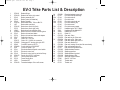
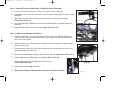
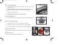
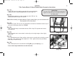
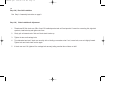
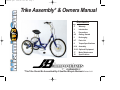
ev3man99.qxd
6/22/99 1:20 PM
Page 1
Trike Assembly* & Owners Manual
Page
Contents
2
Warranty
3
Introduction
4
Precautions
4-5
Getting Started
5
Recharging
6-7
Parts List
8
Torque Specifications
8-14
Assembly
15-16 Optional Equipment
17
Motor Maintenance
18
Specifications
*This Trike Should Be Assembled By A Qualified Bicycle Mechanic Revised 3-99
ev3man99.qxd
2
6/22/99 1:20 PM
Page 2
Attach this coupon to your receipt and present both to dealer if service is required.
Owner's name___________________________________________________________________________________
Address________________________________________________________________________________________
City____________________________
Date purchased__________________
State__________________________
Zip_______________________
Model no. _______________________ Serial no.______________________
Dealer's name___________________________________________________________________________________
Address________________________________________________________________________________________
City ________________________
State _______________________
Zip_____________________________
Miami Sun EV-3 Limited Warranty
Subject to the following terms, limitations and condition this is your limited warranty.
1.
FRAME, is warranted to be free from defects in materials and workmanship for 3 years from the date of purchase. Bending of
frame and any other components along with industrial and/or commercial use are excluded from
this warranty. Bending is abuse and not covered.
2.
The Electric Motor (excluding brushes) is warranted to be free from defects in materials and workmanship for 1 year from
date of purchase.
3.
The fork, rear unit and other components (excluding tires, tubes. cables and brake shoes) are warranted for 90 days from
date of purchase.
All claims must be submitted with your bill of sale and serial number. Shipping and labor charges are not included in the warranty.
This limited warranty does not cover personal injuries, damage or failure due to accident, alteration, abuse, wear and tear, neglect,
improper assembly or maintenance.
The warranty is void if the trike is sold, given away, modified, used in stunts, ridden off road, rented, used in commerce or any similar activities.
Miami Sun EV-3 liability under this warranty is no greater than the amount of the original purchase and will not be liable for incidental or consequential damages.
See your authorized Miami EV-3 Sun dealer for service and replacement.
ev3man99.qxd
6/22/99 1:20 PM
Page 3
PLEASE READ THIS MANUAL BEFORE RIDING YOUR ADULT EV-3 TRIKE
We included in the preparation of this manual WARNINGS and INFORMATION for your safety.
•
GENERAL WARNING: Riding an electric powered trike can be hazardous. When on a trike you could have an accident resulting in
injury or even death. This manual makes an effort to give you enough information that could prevent riding into danger. We can
not cover all contingencies but hope to make you an informed and aware rider.
•
Municipal bicycle regulations also apply to tricycles. Most states and municipalities have regulations. It's up to you to research
those regulations and become informed. Your dealer may be able to help you with this information.
Since you will be sharing the road at times with other vehicles a good rule to follow is "If you can't do it with a car or bicycle, don't do
it with a trike."
•
A trikes widest point is behind you, if the front goes by an obstacle there is no guarantee that the rear wheels will also clear.
When riding, you must give clearance to the edge of the road or sidewalk. Stay clear of potholes and be aware that you can lose
control if any wheels should drop into a hole or ditch.
•
Always ride defensivly. Watch out for the unexpected. This means everything from cars to children, pets and rough road surfaces. Be
prepared to avoid danger. ALWAYS WEAR A BICYCLE HELMET. We recommend buying your helmet from a dealer that can
fit and instruct you on the correct way to wear a helmet. Protecting your head is your primary safety responsibility.
•
Always wear a CPSC, ANZI, ASTM, or SNELL approved bicycle helmet. CPSC is the federal standard and all helmets
must comply by 1999.
•
Check your tires for proper air pressure. If you need to inflate them do not inflate over the recommended air pressure on the side
wall of your tires. If using a compressor or the air hose at a gas station be very careful not to blow the tire off the rim. Check the hard
ness of the tire and stop inflating to check the air pressure. Do not over inflate.
•
Test your front brake and rear brake and make sure they stop the trike. If you have any doubts do not ride your trike and see your
dealer. All EV-3 trikes are equipped with front and rear brakes as standard equipment. Under no circumstance should the brakes be
removed. They are also your parking brakes. When stopping your Trike apply both the front and rear brakes together for a safe
smooth stop.
•
Check that the handlebar is tight and that the ends are plugged. Now check the saddle for tightness.
•
Safety check: Apply your front and rear brakes and rock your trike back and forth. If you hear or feel a movement coming from the
fork or front wheel or any other part of the trike, DO NOT RIDE. Have your dealer or qualified mechanic check the trike.
CHECKLIST BEFORE RIDING
3
ev3man99.qxd
6/22/99 1:20 PM
Page 4
4
PRECAUTIONS
•
A trike does not handle like a bicycle, therefore, you cannot lean into a turn. All wheels must be on the ground at all times. Do not
make sudden changes of direction you could unbalance the trike and have an accident.
•
We suggest you practice riding in a quiet area to get the feel of the trike.
•
When beginning to ride, stay at a slow speed. You must acclimate yourself to handling and turning this three wheeler. If you feel insecure, slow down, and proceed at a slower pace. With practice, you will get comfortable riding and stopping.
•
Never ride with your ears covered with earphones or anything else that would prevent hearing. Hearing your surroundings is important
for your safety.
•
We recommend that you not ride at night, or at times of reduced visibility. If you should ride at night or during reduced visibility, you
must outfit your trike with a front white light and a rear red light . Relying solely on reflectors is not adequate protection. Most municipalities require lights for night riding. Your bicycle dealer can help you in selecting the correct lighting system for your needs.
•
Avoid riding on rainy days since you don't have the same control, handling, and stopping power as on a dry day.
•
When making a turn or stopping use hand signals to show your intent. To signal use your left arm while maintaining control of the throttle with your right.
•
Always ride with the flow of traffic never against traffic
• The rear basket is only intended for light storage. DO NOT EVER PUT A CHILD, PERSON OR PET IN THE BASKET! They could be
seriously injured by the turning wheel and/or the moving parts. There is also the risk of the passenger falling out of the basket.
The trike is made for one person only and the basket is not built to hold a passenger.
•
Weight capacity is 250 lbs.
GETTING STARTED
TO GET STARTED
1. Turn the key in the control box (located under your seat) to the on position. A red LED light will go on showing that the battery is in
operation.
2. Pedal until a fast walking speed is achieved twist your control grip and the motor will start.
3. You're on your way.
If the switch is left on and the trike is not in use, the system will shut down in five minutes. To restart you must reset the system by switching the key off, then on again.
A flashing LED light on the control unit means insufficient battery power. This would be time to recharge.
ev3man99.qxd
6/22/99 1:20 PM
Page 5
GETTING STARTED (continued)
5
You can control the rate of power with your throttle grip. The more you twist, the more power. Practice the various twist positions to get
familiar with the power released. We recommend using a combination of Electric power with pedal power to extend your powered range.
It's also good for your own physical fitness.
If you slow below a walking speed the motor will cut off and you need to pedal assist again to turn it back on.
Take special care to SLOW DOWN in turns. With electric power you can easily go into a turn too fast and turn the trike over causing injury
or even death. TAKE TURNS SLOWLY, brake before turning and practice turns in an open area so that you will be comfortable taking
them.
When your ride is over turn off the key and take it with you. NEVER LEAVE THE KEY IN THE CONTROL BOX. ALWAYS LOCK YOUR
TRIKE if you are no using it. THIS IS NOT A TOY!!
Do not allow children to operate this trike without adult supervision.
RECHARGING THE BATTERY
Keep the charger in a protected and covered area. The charger cannot be exposed to water or humidity and must be used in a well-ventilated space preferably outdoors under a covered and dry area.
The battery case can be removed by unhooking the holding strap, disconnecting the control cable and bringing in the battery to connect to
the charger.
If the motor is used for a long time and overheats it will shut off. It can be started again after it cools off. The same thing applies to the
charger if it gets too hot it will shut off and restart when cooled down.
If the battery charge gets very low the red LED will blink and the motor will shut off. It's now time to recharge the battery.
To recharge the battery use only the charger provided with the EV-3. Any other charger could seriously damage the batteries and motor or
injure the user.
Our charger can be plugged into a standard 110v receptacle. The battery connection is a three-prong plug with a lock ring. Please keep
water away from the charger and battery case. Our charger is calibrated to correctly charge our battery and you should check the lights
until full charge is achieved. Full charge takes from 6 to 8 hours. The green light on the charger will blink until their is a full charge then it
will stay a steady green.
If a month goes by between riding the trike, recharge the battery before using.
This Pb-acid battery does not remember its charge. Multiple charging does not shorten its life.
Do not allow children to touch the battery.
ev3man99.qxd
6/22/99 1:21 PM
6
Page 6
EV-3 Trike Parts List & Description
19
44
27
6
26c
4
5
7
40
26b
28
43
1
2
29
38
42
41
19a
25a
9
39
3
26
20
8
22
26
21
26
31 33 35
12
11
35
24
13
36
16
14
15 17
25a
30
25
37
23
12
10
18
3a
ev3man99.qxd
6/22/99 1:21 PM
Page 7
EV-3 Trike Parts List & Description
1
2
3
3
3a
4
5
6
7
8
9
10
11
12
13
14
15
16
17
18
19
19a
20
21
22
23
24
6702181
6702180
67142
67148
67149
6702146
1427
6702145
67152
13395
6702290
67143
67154
67147
1603
6702171
6702295
22240
6702068
2232
67141
67139
67140
6702155
67131
67130
18521
6702199
Basket fittings
Basket trike white vinyl coated
Battery assembly 36v.
Battery case (w/o batteries)
Battery charger
Brake cable 890 X 760 mm Blk. Frt.
Brake cable rear black
Brake lever w/lock left (front)
Brake lever w/lock right (rear)
Brake shoe front cantilever white
Brake unit front Cantilever w/locking lever
Brake unit rear band brake
Brake unit rear band brake axle adapter
Cable clip w/screw
Chain 1/2 X 1/8 112L
Chain 1/2 X 1/8 50L for conversion
Chainguard CP hockey stick style OPC
Crank B.B. parts set 24 TPI
Crank chainring 1/2X1/8"X36T
Crank one piece 5-1/2"
Electric/mechanical Speed control switch
Electronic control unit
Electronic control unit key switch w/2-keys
Fender front 24" S.S. w/braces
Fork w/pivots electric blue
Frame electric blue
Freewheel 22T
Freewheel adapter 15mm w/2 screws
24
25
25a
26
26a
26b
26c
27
28
29
30
31
33
35
36
37
38
39
40
40
41
42
43
44
6702201
67135
67144
67133
67138
67134
67146
67145
67137
3330
35002
41118
6702191
6702203
6702204
6702193
6702192
6702184
6702210
67132
6702140
6702135
6702132
6702130
6702175
57380
67136
67153
Freewheel adapter screw only
Front hub axle cap assembly
Front hub axle nut
Front hub motor
Front hub motor brush set
Front hub retaining clip
Front hub sensor
Front hub sensor magnet
Handlebar grips 7/8 & 1” black
Handlebar hi-rise Wald # 870
Headset 30.0 X 27.0
Pedal 1/2 “
Rear axle 15mm
Rear axle key for 15mm axle
Rear axle nut for 15mm axle
Rear axle spacer Idler side L.H.
Rear axle washer R.H.
Rear unit bearing 15mm (also fits rear wheels)
Rear unit hardware 4pc set
Rear unit housing electric blue
Saddle hardware western
Saddle support bar
Saddle Western Imported
Saddle Western USA
Seat post chrome 28.6mm
Stem 6" X .875mm
Throttle cable
Throttle unit
7
ev3man99.qxd
8
6/22/99 1:21 PM
Page 8
Torque Specifications (cont.)
Torque Specifications
Axle nut front
Brake front cantilever pinch bolt
Brake lever bolt
Brake rear drum cable pinch nut
Crank arm fixed cone
Crank arm lock nut
Headset lock nut
180 to 240
36 to 48
24 to 36
48 to 72
min. 300
min. 240
min. 300
inch pounds
inch pounds
inch pounds
inch pounds
inch pounds
inch pounds
inch pounds
Pedals
Rear unit attaching nuts
Saddle clamp nut
Seat post binder nut
Seat strut (lower) nut
Stem binder nut
Stem expander bolt
350
300
200
150
300
170
175
to
to
to
to
to
to
400
300
180
400
180
250
inch pounds
inch pounds
inch pounds
inch pounds
inch pounds
inch pounds
inch pounds
Assembly
Step 1) Attaching Rear Unit To Frame
Installing the rear unit to the frame is a simple matter of attaching two pairs of long
and short carriage bolts. Please proceed in the following sequence:
A.
Install loosely the two large carriage bolts (A) with their nuts and washers, to the
two holes in the end of the trike frame stay. The heads of the bolts are on the
inside of the frame.
B.
Slide the arms of assembled unit between rear frame stays, up to and between
large carriage bolt heads and frame slot. Finger tighten nuts.
C.
Align the first most forward holes on unit arms with rear frame slot. Attach the two
shorter carriage bolts (B) and finger tighten. Note that the heads are inside
the frame. (Fig. 1)
D.
Make sure that axle flange on unit is to the right side of unit and frame. Also unit
must be installed with support bars up, so that the basket can rest on them.
A
A
B
B
(Fig. 1)
ev3man99.qxd
6/22/99 1:21 PM
Page 9
9
Step 2) Chain Installation & Adjustment of F.W. Unit
A.
Unsnap chain, thread chain around chainwheel and freewheel. Reconnect chain with two-piece connecting link.
B.
Slowly pull rear unit towards end of trike until chain slack is taken up.
C.
Tighten the two short carriage bolts. (A) (Fig. 2)
D.
Turn chainwheel and see if chain runs smoothly with no binding or
excessive noise. If not, loosen bolts, move unit slightly forward. Tighten
bolts and check chain function again.
E.
Make sure the chain runs straight and true with the chainwheel.
F.
If chain now runs O.K. tighten all four carriage bolts (A & B) securely,
taking care that the unit does not shift. (Torque 300 to 400 in.lbs.)
A
A
B
B
(Fig. 2)
G. Now install chainguard using two screws (C) provided. Make sure chain
does not rub on chainguard. (Fig. 3)
C
(Fig. 3)
C
Note: Long bolts (A) will hold seat brace in Step 10
ev3man99.qxd
6/22/99 1:21 PM
Page 10
10
Step 3) Front Wheel Alignment & Attachment
C
A. Place fender braces on each side of axle. Attach fender braces to fork eyelets
with screws provided. (Fig. 4)
B. Remove axle nuts and safety washers. Drop wheel in fork and center. Electric
wires belong on the same side as the chainwheel.
C. Replace safety washers and install axle cover bracket (A) on side that has the
wires. (Fig. 5)
(Fig. 4)
D. Thread on axle nuts, center wheel and tighten. (Torque 180 to 240 in. lbs.)
E. Connect wires (B) and install axle cover with two metal screws to the cover
bracket. (A)
Please note to take extra care in connecting the male and female plugs (B) on the wire
and be sure that the parts are well seated.
F. “Warning: Do not ride without safety fork washers. (C)”
(Fig. 5)
B
A
ev3man99.qxd
6/22/99 1:21 PM
Page 11
Step 4) Attaching Pedals
11
A. Each pedal axle is marked with "R" (right) or "L" (left) (Fig. 6). Install them in their
correct position. Note that the left pedal tightens by turning counter clockwise and
that the right tightens clockwise. The right side is the chain side.
(Torque 300 in. lbs.)
R
(Fig. 6)
Step 5) Attaching Rear Wheels
A.
Both wheels are the same. The hub flanges have three holes that fit the studs on the axle flange. (A)
Install the drive wheel first,(right side) (Fig. 7). Add axle washer on the outside and snug down lock
ing nut.
Over-tightening will damage the bearings.
B.
Now put the second wheel on left side. This wheel is the idler. First slip on the spacer, then the
wheel, followed by a washer and the locking nut until it touches the bearing. Now back off nut 1/8 of
a turn.
Again Do Not Over Tighten. Leave Some Play.
C.
VERY IMPORTANT: It is critical for the protection of the bearings, that you inform your customer
that the idler wheel requires a slight amount of play in order to prevent bearing damage.
A
(Fig. 7)
Step 6) Steering Head Adjustment
A. Place trike in an upright position on floor, loosen head lock nut and the
adjusting cone.
B. Re-tighten adjusting cone finger-tight. Turn the fork from side to side. Fork
should turn with no rocking or free play.
C. Securely tighten head locking nut down onto washer.
(Torque min. 300 in. lbs.)
(Fig. 8)
ev3man99.qxd
6/22/99 1:21 PM
Page 12
12
Step 7) Attaching Stem & Handlebar
A.
Loosen expander bolt on stem and insert stem into head tube.
B.
Insert handlebar through stem, center it and adjust to desired angle. Tighten handlebar binder nut securely.
(Torque 170 to 180 in. lbs.)
C.
Place handlebar and stem at right angle to length of trike and tighten stem expander bolt securely.
(Torque 175 to 250 in. lbs.)
D.
“Warning: The stem minimum insert mark must be inside the head tube.”
(Fig. 9)
Step 8) Installation of Cantilever Brakes
A.
Loosen screw on brake lever attachment bracket until lever slides over left handle of handlebar. Do
not tighten screw yet.
B.
Slide grip on handlebar, making sure that grips are all the way to the end of the handlebar. Do not
use any type of lubricant to install grips.
C.
Slide brake lever back, as close as possible, to grip on handlebar. Turn lever to desired angle and tighten securely. (Torque 24 to 36 in. lbs.)
D. Install brake arms by inserting the end of the spring into the middle hole on the fork stud and tighten arm.
(Fig. 10)
E. Insert the cable end-nipple into slot on brake lever.
F.
Insert the cable into link wire.
G. Set link wire end-fitting into hook side of brake arch. Install the cable through the link wire housing and
fixing bolt.
H. Push both brake arches toward the rim, allowing 3 mm. clearance between brake shoes and rim. Tighten
the wire fixing nut. (Torque 36 to 48 in. lbs.)
I.
Cut off excess cable, leaving about 25 mm. Put protective cap on cable end and crimp with pliers.
J. “Warning: Removal of the front reflector bracket could result in serious injury if the brake cable
snaps and the link wire snags the front tire.”
(Fig. 11)
ev3man99.qxd
6/22/99 1:21 PM
Page 13
Step 9) Attaching Throttle and Band Brake To Right Hand Side Of Handlebar.
A.
Loosen screw and slide brake lever to end ,do not tighten screw yet. (Fig. 12)
B.
Slide throttle control to end of bar and back off a bit to prevent binding. Adjust to correct position
and tighten.
C.
Slide brake lever back to end of throttle control then turns to correct angle and tighten.
(Torque 24 to 36 in. lbs.)
D.
13
(Fig. 12)
Go to band brake (Fig. 13) attached to rear unit and thread cable thru band brake spring and
binder bolt.
E. Engage brake and tighten pinch bolt securely. (Torque 48 to 72 in. lbs.)
Step 10) Western Seat Assembly & Installation
A.
Place seat upside down. Clip on the two seat brace clips to seat brace (Fig. 14). Remove two
nuts from studs in back of seat and attach brace to seat. Tighten nuts. (Facing Forward: Brace
should be in front of studs).
B.
Reposition saddle clamp so that seat post is toward middle. Place seat post on seat and tighten
seat post clamp snugly.
C.
Place seat post into seat tube of trike. Put the middle holes on the seat brace into the two long
carriage bolts (Fig. 15). Attach nuts.
D.
Adjust seat to desired height and tighten seat post binder securely. (Torque 150 to 180 in. lbs.)
E.
Tighten saddle clamp bolt (Fig. 14) securely. (Torque 200 to 300 in. lbs.)
F.
Tighten seat brace carriage bolts (Fig. 15) on frame securely.
(Torque 300 to 400 in. lbs.)
(Fig. 13)
(Fig.14)
G. Tighten seat brace clips (Fig. 15) securely.
H.
“Warning: The seat post minimum insert mark must be inside the seat tube.”
(Fig. 15)
ev3man99.qxd
6/22/99 1:21 PM
Page 14
14
Step 11) Attaching Vinyl Basket
A.
With the reflector bracket on basket facing rear, center the basket onto the rear unit
basket support bars.
B.
Align the two holes of unit basket support bar with the holes of the basket
attaching brace (Fig. 16). Attach nuts and bolts and finger tighten. Repeat for other
bar.
C.
Tighten all nuts and bolts securely .
D.
Warning: Never put a child, person or pet in the basket.
(Fig.16)
Step 12) Install Battery Pack
A. Place the battery pack into its steel bracket and attach the safety strap. (Fig. 17)
Step 13) How To Attach Reflectors
A.
Attach the white reflector to the reflector bracket on fork (Fig. 18).
B.
Attach the red reflector to the reflector bracket on rear of basket (Fig. 19).
C.
Attach the wheel reflectors opposite valve stems on the spokes (Fig. 20).
(Fig.17)
Step 14) Check Tire Inflation
Inflate tires per tire manufactures recommendation printed on the sidewall of the
tire.
Step 15) Final Check
Double check that all fasteners are tightened properly.
(Fig.18)
(Fig.19)
(Fig.20)
ev3man99.qxd
6/22/99 1:21 PM
Page 15
Optional
Trike Coaster Brake & 3-Speed Coaster Brake Conversion Instructions
Step 1-A)
Prepare CB hub unit by attaching sprocket with concave side facing
outward from hub. Concave sprocket faces in for the 3-spd. C.B.
Step 2-A)
Slide spacing washers on to axle on brake arm side of CB unit. No
washers are used on 3-spd. C.B. hub unit.
15
Helpful Hint:
The trike CB & 3-spd. C.B. hub units are adjusted &
aligned the same way as you would a CB wheel on
an ordinary bike.
Note: When installing a coaster brake or 3-spd. coaster brake, you must substitute the
fixed sprocket for the free wheel.
Step 3-A)
Place CB or 3-spd. C.B. hub unit into special frame conversion slot brackets located on top of
rear bottom frame stays, attach nuts. (Fig.22)
Step 4-A)
Attach chain (84 Links) to chainwheel and outer CB or 3-spd. C.B. sprocket and connect
connecting link.
Step 5-A)
Pull hub towards rear to remove slack in chain, align unit at a right angle to frame, lightly
tighten nuts.
(Fig. 21)
Step 6-A)
Turn chainwheel and note. Chain condition, chain must run smoothly with no binding or excessive noise. If not, loosen nuts and re-adjust unit. If O.K., tighten nuts securely and attach
brake strap to bottom left stay.
Step 7-A)
Attach fixed sprocket onto rear trike axle. See Fig. 4B (pg. 9) and step 8 (pg. 11)
TOWARD
FRONT
You are now ready to attach the rear unit to the trike.
(Fig. 22)
ev3man99.qxd
6/22/99 1:21 PM
Page 16
16
Step 8-A) Rear Unit Installation
See Step 1 of assembly instructions on page 8.
Step 9-A)
Chain Installation & Adjustment
1.
Thread small 50 Link chain over CB or 3-spd. C.B. welded sprocket and unit fixed sprocket. Connect the connecting link, align both
sprockets, install axle key and tighten set screw.
2.
Slowly pull unit towards end of trike until chain slack is taken up.
3.
Tighten the two small carriage bolts.
4.
Turn chainwheel and see if chain runs smoothly with no binding or excessive noise. If not, loosen bolts, move unit slightly forward.
Tighten bolts and check chain function again.
5.
If chain now runs O.K. tighten all four carriage bolts securely, taking care that the unit does not shift.
ev3man99.qxd
6/22/99 1:22 PM
Page 17
(Fig. 23)
Wire side
17
(Fig. 24)
Magnet side
A
(Fig. 25)
Electric Motor Maintainence
Your hub motor is designed to be virtually maintence free. If you notice a decline in performance (other than a
low battery charge) it is most likely time to change the brushes inside the motor. It is advised that you bring
your trike to the dealer for this service.
1.
Turn your trike upside down.
a. Disconnect the power leads to the motor.
b. Remove axle nuts, washers and retaining clips.
2.
Loosen brake and remove front wheel assembly.
3.
Remove the 6 hex head screws (A) locknut and snapring from wire side of hub (Fig. 25).
4.
Carefully remove cover plate to expose brush housings (Fig. 26).
5.
Carefully remove black brush housing caps and remove old brushes (B) (Fig. 27).
6.
Reinstall new set of brushes (Fig. 28). Always replace both brushes at the same time to promote even wear.
7.
Re-attach cover plate and DO NOT FORGET THE RETAINING CLIP!
8.
Re-install wheel onto trike, see page 10 Step 3.
(Fig. 26)
B
(Fig. 27)
(Fig. 28)
ev3man99.qxd
6/22/99 1:22 PM
Page 18
Miami Sun EV-3 Specifications:
Voltage:
Batteries:
Top Speed*:
Range*:
Charge time:
Charger:
Wheel size:
Electric controls :
Security:
Safety:
W eight capacity:
Color:
Options:
36 volt DC
3-12volt Sealed Gel Cell pbAcid (no memory)
9 mph
15 miles per charge
6 to 8 hours
UL approved fully automatic
24X1.75” front, 20X1.75” rear
Solid state
Mechanical-electric speed control
Thermal overload protection
Replaceable fuses
Key switch
Parking brakes
Motor engages only after pedaling
Automatic low speed cutoff
Spring loaded twist grip throttle
Automatic shut down if not in use
Low charge indicator
Front and rear hand brakes with parking locks
250 lbs. (passenger and cargo)
Electric blue
3-speed coaster brake system and coaster brake system
* Speed and distance are with out pedal assistance. Individual results will vary due to conditions.
Specifications subject to change without notice.