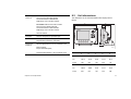
1
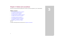
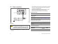
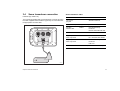
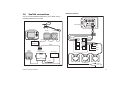
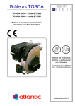
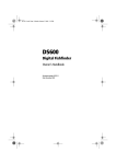
A-Series
Multi-function display
Installation instructions
A50, A50D, A57D, A70 and A70D models
Trademarks and registered trademarks
Autohelm, HSB, RayTech Navigator, Sail Pilot, SeaTalk and Sportpilot are UK registered trademarks of Raymarine UK Limited.
Pathfinder and Raymarine are UK registered trademarks of Raymarine Holdings Limited. 45STV, 60STV, AST, Autoadapt, Auto GST,
AutoSeastate, AutoTrim, Bidata, G-Series, HDFI, LifeTag, Marine
Intelligence, Maxiview, On Board, Raychart, Raynav, Raypilot, RayTalk, Raystar, ST40, ST60+, Seaclutter, Smart Route, Tridata and
Waypoint Navigation are trademarks of Raymarine UK Limited.
All other product names are trademarks or registered trademarks of
their respective owners.
© Raymarine UK Ltd. 2008
Document number: 87102-1
Date: August 2008
Contents
Important information............................................. 5
Warnings and Cautions .................................................... 5
TFT LCD displays ............................................................. 6
Water ingress.................................................................... 6
Disclaimers ....................................................................... 6
EMC installation guidelines............................................... 7
Sonar transducer connection .................................. 23
NMEA 0183 connections......................................... 24
SeaTalk connections ............................................... 25
External GPS Connection ....................................... 26
SeaTalkng connections............................................ 26
NMEA 2000 connection........................................... 27
Declaration of conformity .................................................. 8
Product disposal ............................................................... 8
Chapter 4:Location and mounting....................... 29
Warranty ........................................................................... 8
Unit dimensions....................................................... 30
Selecting a location for the unit ............................... 31
Bracket mounting .................................................... 32
Panel mounting ....................................................... 35
About this manual ............................................................. 8
Chapter 2:Planning the installation..................... 11
Handbook information ............................................. 12
Installation overview................................................ 13
A-Series systems .................................................... 13
Chapter 5:System checks..................................... 37
Pack contents.......................................................... 16
Tools ....................................................................... 17
Initial power on test ................................................. 38
External GPS setting ............................................... 38
GPS Check.............................................................. 39
Transducer check.................................................... 39
Set the language ..................................................... 40
Chapter 3:Cables and connections ..................... 19
Chapter 6:Troubleshooting .................................. 41
General wiring instructions...................................... 20
Connection overview............................................... 21
Power connection.................................................... 22
Power up ................................................................. 42
GPS......................................................................... 43
Fishfinder / Sonar transducer .................................. 44
Core system.................................................................... 13
Extended system ............................................................ 14
3
System data.............................................................45
Chapter 7:Technical support ................................47
Raymarine technical support ...................................48
Web .................................................................................48
Contacting Raymarine in the North America ...................48
Contacting Raymarine in Europe.....................................49
Navionics contact details .........................................49
Sirius contact details ................................................50
Chapter 8:Technical Specification .......................51
Technical specification.............................................52
Unit dimensions .......................................................53
NMEA Messages .....................................................54
Chapter 9:Accessories ..........................................55
Options and accessories .........................................56
Mounting options .............................................................56
SeaTalk accessories .......................................................56
SeaTalkng accessories ....................................................56
Transducers and associated cables ................................57
Spare parts ..............................................................58
4
A-Series display - Installation instructions
Important information
Warnings and Cautions
WARNING: Product installation
This equipment must be installed in accordance
with the Raymarine instructions provided. Failure
to do so could result in poor product performance,
personal injury, and/or damage to your boat.
WARNING: Potential ignition sources
The equipment must NOT be installed in
hazardous or flammable atmospheres such as an
engine room.
WARNING: High voltages
WARNING: Service and Maintenance
This product contains no user serviceable components. Please refer all maintenance and repair to
authorized Raymarine dealers.
Unauthorized repair may affect your warranty.
CAUTION: Switch off power supply
Switch OFF the power supply to the unit before
connecting or disconnecting any cables or
connections. Failure to do so may cause sparks or
result in irreparable damage to the unit.
CAUTION: Transducer cable
The display unit contains high voltages. DO NOT
remove the display unit covers or attempt to
service the equipment.
DO NOT cut, shorten, splice the transducer cable
or remove the connector. If the cable is cut, it
cannot repaired. Cutting the cable will also void
the warranty.
WARNING: Switch off power supply
CAUTION: CompactFlash cards
Make sure you have set the boat’s power supply to
OFF before you start installing this product.
Unless otherwise stated connect and disconnect
equipment only with the power supply switched
OFF.
When installing CompactFlash cards ensure that
the card is fitted the correct way around. DO NOT
try to force the card into position as this may
result in irreparable damage to the card.
Removing the CompactFlash card while information is being written to or read from it may cause
damage to the card and loss of all data.
DO NOT use a metallic instrument such as a
screwdriver or pliers to remove a card, as doing
this can cause irreparable damage.
WARNING: Grounding
This display is not intended for use on “positive”
ground boats. All power input screens, ground
and cable drain wires must be connected directly
to the boats ground.
Important information
5
CAUTION: Water ingress
To prevent the ingress of water and consequent
damage to the display, ensure that the chart card
door is firmly closed. This can be confirmed by an
audible click.
CAUTION: Sun covers
To provide protection against the damaging
effects of ultra violet (UV) light, use the sun covers
when equipment is not in use.
CAUTION: Cleaning
DO NOT use acid, ammonia based or abrasive
products.
DO NOT use commercial high pressure washing
(jet wash) equipment.
TFT LCD displays
The colors of the display may seem to vary when viewed against a
colored background or in colored light. This is a perfectly normal
effect that can be seen with all color Liquid Crystal Displays (LCDs).
In common with all Thin Film Transistor (TFT) LCD units, the screen
may exhibit a few (less than 5) wrongly illuminated pixels. These
may appear as black pixels in a light area of the screen or as colored pixels in black areas.
6
Water ingress
As it exceeds the water proof rating capacity outlined by standards
IPX6, subjecting any Raymarine equipment to commercial high
pressure washing equipment may cause water intrusion and subsequent equipment failure. Raymarine will not warrant equipment
subjected to high pressure washing.
Disclaimers
Electronic charts are an aid to navigation designed to facilitate the
use of authorized government charts, not to replace them. Only official government charts and notices to mariners contain the current
information needed for safe navigation. The Captain is responsible
for their prudent use. The A-Series Multifunction Display and its
charts do not therefore exclude the user from carrying the required
official charts and documents.
Raymarine does not warrant that this product is error-free or that it is
compatible with products manufactured by any person or entity
other than Raymarine.
This product uses digital chart data, and electronic information from
the Global positioning System (GPS) which may contain errors.
Raymarine does not warrant the accuracy of such information and
you are advised that errors in such information may cause the product to malfunction. Raymarine is not responsible for damages or
injuries caused by your use or inability to use the product, by the
interaction of the product with products manufactured by others, or
by errors in chart data or information utilized by the product and supplied by third parties.
A-Series display - Installation instructions
Multi-media chart cards
The A-Series Multifunction Display is pre-loaded with Navionics
chart data. If you wish to use different chart data, you can insert
Navionics chart cards into the CompactFlash card slot on the unit.
When archiving data, Raymarine recommends the use of SanDisk
CF memory cards. Other brands of CF memory card may not work
in your unit.
EMC installation guidelines
All Raymarine equipment and accessories are designed to the best
industry standards for use in the recreational marine environment.
Their design and manufacture conforms to the appropriate Electromagnetic Compatibility (EMC) standards, but correct installation is
required to ensure that performance is not compromised. Although
every effort has been taken to ensure that they will perform under all
conditions. It is important to understand what factors could affect the
operation of the equipment.
The guidelines given here describe the conditions for optimum EMC
performance, but it is recognized that it may not be possible to meet
all of these conditions in all situations. To ensure the best possible
conditions for EMC performance within the constraints imposed by
any location, always ensure the maximum separation possible
between different items of electrical equipment.
•
Place equipment at least 5ft (1.5 m) from any equipment transmitting or cables carrying radio signals, e.g. VHF radios, cables
and antennas. In the case of SSB radios, the distance should be
increased to 7ft (2 m).
•
Place equipment more than 7ft (2 m) from the path of a radar
beam. A radar beam can normally be assumed to spread 20 degrees above and below the radiating element.
•
The equipment is supplied from a separate battery from that
used for engine start. Voltage drops below 10 V and starter motor transients can cause the equipment to reset. This will not
damage the equipment, but may cause the loss of some information and may change the operating mode.
•
Cables are not cut or extended unless doing so is detailed in the
installation manual.
Remember
Where constraints on the installation prevent any of the above
recommendations:
•
Important information
Always allow the maximum separation possible between different items of electrical equipment. This will provide the best
conditions for EMC performance for the installation.
7
Suppression ferrites
Raymarine cables may be fitted with suppression ferrites. These are
important for correct EMC performance. Any ferrite removed to facilitate installation must be replaced in the original position
immediately installation is complete.
Use only ferrites of the correct type, supplied by Raymarine authorized dealers.
Connections to other equipment
If Raymarine equipment is to be connected to other equipment
using a cable not supplied by Raymarine, a suppression ferrite must
always be attached to the cable that is closest to the Raymarine
unit.
Declaration of conformity
Raymarine Ltd. declare that the A-Series Multifunction Displays are
in compliance with the essential requirements of EMC directive
2004/108/EC.
The original Declaration of Conformity certificate may be viewed on
the relevant product page at www.raymarine.com
Product disposal
The crossed out wheeled bin symbol, illustrated above, and found
on our products, signifies that this product should not be disposed of
in general waste or landfill.
Please contact your local dealer, national distributor or Raymarine
Technical Services for information on product disposal.
Warranty
To register your Raymarine A-Series Multifunction Display ownership, please take a few minutes to fill out the warranty registration
card found in the box, or visit www.raymarine.com and register online.
It is important that you register your product to receive full warranty
benefits. Your unit package includes a barcode label indicating the
serial number of the unit. You should stick this label to the warranty
registration card.
About this manual
This handbook contains important information on the installation,
operation and maintenance of your A-Series Multifunction display.
The equipment described within is intended for use on leisure
marine boats and workboats not covered by International Maritime
Organization (IMO) and Safety of Life at Sea (SOLAS) Carriage
Regulations.
The Waste Electrical and Electronic Equipment (WEEE)
Directive requires the recycling of waste electrical and electronic equipment. Whilst the WEEE Directive does not apply
to some Raymarine products, we support its policy and ask
you to be aware of how to dispose of this product.
8
A-Series display - Installation instructions
Technical accuracy
To the best of our knowledge, the information in this handbook was
correct as it went to press. However, Raymarine cannot accept liability for any inaccuracies or omissions it may contain. In addition,
our policy of continuous product improvement may change specifications without notice. As a result, Raymarine cannot accept liability
for any differences between the product and the handbook.
Important information
9
10
A-Series display - Installation instructions
Chapter 2: Planning the installation
This chapter provides information to help you prepare for the A-Series installation.
Chapter contents
•
2.1 Handbook information on page 12
•
2.2 Installation overview on page 13
•
2.3 A-Series systems on page 13
•
2.4 Pack contents on page 16
•
2.5 Tools on page 17
11
2
2.1
Handbook information
This handbook contains important information on installing your ASeries Multifunction display and covers both freshwater and saltwater variants of the following models:
•
A50 GPS Chartplotter
•
A50D GPS Chartplotter/Fishfinder
•
A57D GPS Chartplotter/Fishfinder
•
A70 GPS Chartplotter
•
A70D GPS Chartplotter/Fishfinder
All documents can be downloaded from:
www.raymarine.com/handbooks.
This document is part of a series of books associated with the
A-Series displays.
A-Series handbooks
Title
Part number
A-Series Installation instructions
87102
A-Series Quick reference guide
86136
A-Series User reference guide (on user CD)
81314
Additional handbooks
Title
Part number
SeaTalkng reference manual
81300
You should also refer to separate instructions provided with any
ancillary equipment.
12
A-Series display - Installation instructions
2.2
Installation overview
Your installation will include the following activities:
Installation task
Refer to
1
Plan your system
- Chapter 2: Planning the
installation
- All installation instructions
2
Obtain all required equipment and
tools.
- Pack contents on page 16
- Tools on page 17
- Chapter 9: Accessories
3
Site all equipment.
- Chapter 4: Location and
mounting
4
Route all cables.
- Chapter 3: Cables and
connections
5
Drill cable and mounting holes.
- Bracket mounting on
page 32
- Panel mounting on
page 35
6
Make all connections into equipment.
- Chapter 3: Cables and
connections
7
Secure all equipment in place.
- Bracket mounting on
page 32
- Panel mounting on
page 35
8
Power on test the system.
Chapter 2: Planning the installation
- System checks on page 37
2.3
A-Series systems
The A-Series display can be used in a number of system types.
Some examples of which are outlined in this section.
Core system
A-Series display
Sonar
transducer
Power IN
D11355-1
The core A-Series system consists of:
•
A-Series multi-function display
•
Internal GPS antenna
•
Sonar transducer on fishfinder (D) models only.
13
Extended system
NMEA 0183 devices
A-Series display
Example:
External
GPS
AIS receiver
or
Pilot
SeaTalk devices
CANCEL
ENTER
MENU
NMEA SeaTalk
converter
SeaTalk
Instrument
CANCEL
ENTER
MENU
SeaTalkng
NMEA 0183
Sonar
transducer
NMEA 0183
Power IN
D11238-2
Your display can connect to various instruments and displays to
share information and so improve the functionality of the system.
These connections may be made using a number of different
protocols.
Fast and accurate data collection and transfer is achieved by using
a combination of the following data protocols:
14
•
SeaTalkng
•
National Marine Electronics Association (NMEA) 0183.
•
NMEA 2000.
Note: You may find that your system does not use all of the
connection types or instrumentation described in this section.
A-Series display - Installation instructions
SeaTalkng
SeaTalkng
(New Generation) is an onboard network utilizing a backbone cable running through the boat. Drop cables go from T
connectors in the backbone up to individual instruments. Devices
that have a low draw can be powered from the network.
NMEA 0183
The standard was specifically intended to allow for a whole network
of marine electronics from any manufacturer to communicate on a
common bus via standardized message types and formats.
See also
For a list of NMEA message types supported, refer to NMEA Messages on page 54.
The NMEA 0183 Data Interface Standard was developed by the
National Marine Electronics Association of America. It is an international standard to enable equipment from many different
manufacturers to be connected together and share information.
The NMEA 0183 standard carries similar information to SeaTalk.
However it has the important difference that one cable will only carry
information in one direction. For this reason NMEA 0183 is generally
used to connect a data receiver and a transmitter together, e.g. a
compass sensor transmitting heading to a radar display.
This information is passed in ‘sentences’, each of which has a three
letter sentence identifier. It is therefore important when checking
compatibility between items that the same sentence identifiers are
used some examples of which are:
•
VTG - carries Course and Speed Over Ground data.
•
GLL - carries latitude and longitude.
•
DBT - carries water depth.
•
MWV - carries relative wind angle and wind speed data.
NMEA 2000
NMEA 2000 offers significant improvements over NMEA 0183, most
notably in speed and connectivity. Up to 50 units can simultaneously
transmit and receive on a single physical bus at any one time, with
each node being physically addressable.
Chapter 2: Planning the installation
15
2.4
Pack contents
Unpack the display unit carefully to prevent damage. Save the carton and packing in case the unit has to be returned for service.
Pack items - All models
All models contain the following items:
Description
A-Series display
Quick release mounting bracket
R62161
Bracket fixing pack
Includes screws and O-ring
R32113
Suncovers
A50 / A50D
A57D
A70 / A70D
Mounting bracket
Part No.
R62158
R62159
R62160
Sonar cable dustcap
Fixing pack
Power / NMEA cable dustcap
Display unit
6.56 (2 m) Power / NMEA cable
R62157
Documentation Pack
Warranty card
SONAR cable dustcap
Power/NMEA cable dustcap
Suncover
Power/NMEA cable
16
D11006-1
A-Series display - Installation instructions
Pack items - Chartplotter / Fishfinder (D) models
2.5
All chartplotter / fishfinder combination models contain the following
additional triducer items:
Tools
You will need the following tools to install your display unit:
Triducer pack
Power
drill
Jig
saw
Adhesive tape
D11236-1
35 mm (1.3/8 in)
hole cutter, bracket mounting
Note: The triducer supplied will be suitable for fresh or saltwater.
Description
Part No.
P58 Transducer pack
P48 Transducer pack
A102138
A102140
Note: The transducer includes an 25 ft (7.62 m)
flying lead for connection to the A-Series unit.
drill bit,
bracket mounting
Screwdriver
File
40 mm (1. 9/16 in)
hole cutter, panel mounting
5 mm (3/16 in) drill bit,
panel mounting
D11007-1
See also
For details of options and accessories see Accessories on page 55.
Chapter 2: Planning the installation
17
18
A-Series display - Installation instructions
Chapter 3: Cables and connections
This section contains information regarding the connection of power and equipment to your A-Series display.
Chapter contents
•
3.1 General wiring instructions on page 20
•
3.2 Connection overview on page 21
•
3.3 Power connection on page 22
•
3.4 Sonar transducer connection on page 23
•
3.5 NMEA 0183 connections on page 24
•
3.6 SeaTalk connections on page 25
•
3.7 External GPS Connection on page 26
•
3.8 SeaTalkng connections on page 26
•
3.9 NMEA 2000 connection on page 27
See also
For details of cable spares and accessories refer to Chapter 9: Accessories.
19
3
3.1
General wiring instructions
•
Do not pull cables through a bulkhead or deckhead using a cord
attached to the connector. This could damage the connections.
Cable types and length
You should always route data cables:
•
Follow the guidelines given in this section to determine appropriate cable types and length.
•
as far apart from other equipment and cables as possible,
•
•
Unless otherwise stated use only standard cables of the correct
type, supplied by Raymarine.
as far away from high current carrying AC and DC power lines
as possible,
•
as far away from antennas as possible.
•
Ensure that any non-Raymarine cables are of the correct quality
and gauge. For example, longer power cable runs may require
larger wire gauges to minimize any voltage drop in a cable.
Strain relief
•
Routing cables
•
No acute bends. Minimum bend radius of 100mm.
Ensure adequate strain relief is provided. Protect connectors
from strain and ensure they will not pull out under extreme sea
conditions.
Circuit isolation
For installations using both AC and DC current:
Minimum bend of cable
100 mm (4 in) radius
D10596-1
Minimum bend
200 mm (8 in)
diameter
•
Protect all cables from physical damage and exposure to heat.
Use trunking or conduit where possible. Avoid running cables
through bilges or doorways, or close to moving or hot objects.
•
Secure cables in place using tie-wraps or lacing twine. Coil any
extra cable and tie it out of the way.
•
Use a watertight feed-through wherever a cable passes through
an exposed bulkhead or deckhead.
20
•
Always use isolating transformers or a separate power-inverter
to run PC’s, processors, displays and other sensitive electronic
instruments or devices.
•
Always use an isolating transformer with Weather FAX audio
cables.
•
Always use and RS232/NMEA converter with optical isolation on
the signal lines.
•
Always make sure that PC’s or other sensitive electronic devices
have a dedicated power circuit.
Cable shielding
Ensure that all data cables are properly shielded that the cable
shielding is intact (e.g. hasn’t been scraped off by being squeezed
through a tight area).
A-Series display - Installation instructions
3.2
Connection overview
GPS Chartplotter / Fishfinder unit (D models)
The cable connections are made to the rear of the display unit.
GPS Chartplotter
SONAR
Chart plotter / Fishfinder
PWR/NMEA
PWR/NMEA
Chart plotter
D11014-1
D11013-1
Chapter 3: Cables and connections
21
3.3
Power connection
SONAR
Chart plotter / Fishfinder
PWR/NMEA
•
Ground cables may be routed to a common point (e.g. within the
switch panel. With a single (appropriately rated) copper braid
connecting to the earthing plate.
•
Use flat tinned copper braid, 30 A rating (1/4 inch) or greater.
Equivalent stranded wire diameter 4mm or greater.
•
Keep the length of the earth braid as short as possible.
A-Series power cable
A-Series display
Red +ve
Black -ve
Cable
Part No
Notes
2 m (6.56 ft)
A50/A57/A70 Power
and NMEA Cable
R62157
Supplied with A-Series unit.
For other cables and accessories refer to Options and accessories on page 56.
Data
A-Series power cable extension
Black drainwire
The following restriction applies to any extension to the power cable:
Ship's ground
D11354-1
Grounding
WARNING: Grounding
This display is not intended for use on “positive”
ground boats. The power input cable drain wires
must be connected directly to the boats ground.
•
22
Use a dedicated earthing plate (e.g. dynaplate) in contact with
the water.
Length (max)
Cable gauge (AWG)
10m (32.8 ft)
14
Fuses & circuit protection
Equipment
Thermal
breaker
Fuse
A50, A50D, A57D, A70, A70D
10A
10A
A-Series display - Installation instructions
3.4
Sonar transducer connection
Sonar transducer cable
Fishfinder (D) models only
Cable
The A-Series is supplied with a sonar transducer. Connect this using
the cable supplied. Other transducer types may be connected with
the appropriate converter cable
7.62 m (25 ft)
flying lead
Part No
Notes
Attached to transducer.
Extension cables (Small 7 way connector)
A-Series display
3 m (9.8 ft)
Extension cable
E66074
Used with the following
transducers
P48, P58, P74, B744V, B60, P36
Transducer converter cables
SONAR
Chart plotter / Fishfinder
PWR/NMEA
Large 7 way male
Small 7 way female
E66066
Used with DSM 300 transducers
B117, P319, P79, B258, B744VL
Large 9 way male
Small 7 way female
E66070
Used with the following
transducers:
L365, L470
For other cables and accessories refer to Options and accessories on page 56
D11240-1
Chapter 3: Cables and connections
23
3.5
NMEA 0183 connections
NMEA 0183 cable
The A-Series has 2 NMEA ports available. These are connected
using the supplied Power/NMEA cable.
Cable
Part No
Notes
2 m (6.56 ft)
A50/A57/A70 Power
and NMEA Cable
R62157
Supplied with A-Series unit.
For other cables and accessories refer to Options and accessories on page 56
SONAR
Chart plotter / Fishfinder
PWR/NMEA
NMEA cable extension
A-Series display
The following restriction applies to any extension to the NMEA
cable:
White
IN
+ve
Green
IN
-ve
Yellow
OUT
+ve
Brown
OUT
-ve
OUT
+ve
OUT
-ve
IN
+ve
IN
-ve
NMEA 0183 DEVICE
4.8k to 38.4 k baud
Orange/ Orange/
White
Green
IN
IN
+ve
-ve
OUT
+ve
OUT
-ve
Length (max)
Cable gauge (AWG)
10 m (32.8 ft)
20
Orange/ Orange/
Yellow
Brown
OUT
OUT
+ve
-ve
IN
+ve
IN
-ve
NMEA 0183 DEVICE
4.8k to 38.4 k baud
D11239-1
24
A-Series display - Installation instructions
3.6
SeaTalk connections
SeaTalk connection
You can connect SeaTalk instruments to your A-Series using a
SeaTalk to NMEA 0183 converter.
SONAR
Chart plotter / Fishfinder
PWR/NMEA
A-Series display
A Series display
SEATALK
ALARM
+ –
SEATALK
SeaTalk
RS232
Brown
NMEA/SeaTalk
Converter
OUT
+ –
Green
White
+ –
IN
+ –
SeaTalk
NMEA
Yellow
NMEA
SeaTalk
instrument
OUT
SeaTalk
instrument
Red
Screen
Yellow
ST6002
controller
Course computer
Power Supply
12V dc
SeaTalk devices
D11242-1
5 A fused,
12 V dc supply
D11243-1
Chapter 3: Cables and connections
25
3.7
External GPS Connection
3.8
SeaTalkng connections
The A-Series has a built in GPS antenna. If you wish to connect an
external GPS antenna it may be either connected via SeaTalk or
NMEA 0183 depending upon the antenna type.
Your A-Series has a rear connector for SeaTalkng systems. It can
use SeaTalkng to communicate with:
•
SeaTalkng instruments (e.g. ST70),
For SeaTalk connection refer to:
•
SeaTalkng autopilots (e.g. ST70 with SmartPilot SPX course
computer),
•
SeaTalk connections on page 25.
•
Separate instructions supplied with your GPS unit.
For NMEA 0183 connection refer to:
•
NMEA 0183 connections on page 24
•
Separate instructions supplied with your GPS unit.
See also
When using an external GPS antenna you must disable to internal
GPS from within the Setup menus. See External GPS setting on
page 38.
SeaTalkng cables
The SeaTalkng system uses the following cables and connections.
Connection /
Cable
Notes
Backbone cables
(various lengths)
The main cable carrying data. Spurs from the backbone are used to connect SeaTalkng devices.
T-piece connectors
Used to make junctions in the backbone to which
devices can then be connected.
Terminators
Required at either end of the backbone.
Spur cables
Used to connect devices.
Devices may be daisy chained or connected directly
to the T-pieces.
For SeaTalkng cables and accessories refer to Options and accessories on
page 56.
For more information refer to the separate SeaTalkng reference manual.
SeaTalkng power
The SeaTalkng bus requires a 12 V power supply. This may be provided from:
26
A-Series display - Installation instructions
•
Raymarine equipment with a regulated 12 V supply. (e.g. a
SmartPilot SPX course computer)
•
Other suitable 12 V supply. (Note the grounding requirements
for the A-Series system, see page page 22.
Note: SeaTalkng does NOT supply power to your A-Series display.
CANCEL
MENU
NMEA 2000 devices are connected using the SeaTalkng bus. The
A-Series can display data received from NMEA 2000 devices (e.g.
data from compatible engines).
ENTER
SeaTalkng backbone
ENTER
NMEA 2000 connection
You may connect NMEA 2000 compatible devices using appropriate
adaptor cables.
Typical SeaTalkng system
CANCEL
3.9
MENU
SeaTalkng backbone
A Series
display
Autopilot
(Course
Computer)
Power Supply
12 V / 24 V dc
SeaTalkng
to DeviceNet cable
NMEA 2000
equipment
(e.g. engine via
appropriate
manufacturers
interface)
D10599-1
12 V dc + Data
D11241-1
Chapter 3: Cables and connections
27
28
A-Series display - Installation instructions
Chapter 4: Location and mounting
This section provides instructions for siting and mounting the A-Series unit.
Chapter contents
•
4.1 Unit dimensions on page 30
•
4.2 Selecting a location for the unit on page 31
•
4.3 Bracket mounting on page 32
•
4.4 Panel mounting on page 35
See also
For the optional panel mounting kit accessory, refer to Mounting options on page 56.
29
4
4.1
Unit dimensions
The dimensions for the A-Series Multifunction Displays are as
follows:
inches
A
B
C
D
E
9.12
6.72
1.68
3.85
0.63
D
A
C
B
E
D11005-1
A
B
C
D
E
mm
200.14
142.14
42.60
97.73
30.13
inches
7.88
5.60
1.68
3.85
1.20
mm
226.64
158.64
42.60
97.73
21.88
inches
8.84
6.25
1.68
3.85
0.86
233.14
170.64
42.60
97.73
15.88
A50 / A50D
A57D
A70 / A70D
mm
30
A-Series display - Installation instructions
4.2
Selecting a location for the unit
•
WARNING: Potential ignition sources
Magnetic compass
Select a location that is at least 3 ft (1 m) away from a magnetic
compass.
•
Cable runs
Select a location that is as close as possible to the boat’s DC
power source.
•
Environmental
Protect the display from physical damage and excessive
vibration.
The equipment must NOT be installed in
hazardous or flammable atmospheres such as an
engine room.
Your A-Series Multifunction display can be installed using the
bracket supplied or panel mounted using an optional panel mount
kit.
Before you install the unit it is important to consider the location:
•
Water ingress
The display is suitable for mounting both above and below
decks. It is waterproof to IPX6 standard. Although the unit is waterproof, it is good practice to locate it in a protected area away
from prolonged and direct exposure to rain and salt spray.
•
Viewing angle
The contrast and colors seen on all LCD units varies slightly with
viewing angle and are best viewed perpendicular to the display.
Avoid locations where excessive reflection will occur in normal
use
•
Access
The mounting location should be easily accessible to enable operation of the front panel controls. There must be sufficient
space behind the unit to enable cable connections to the rear
panel connectors, avoiding tight bends in the cables.
•
Electrical interference
Select a location that is far enough away from devices that may
cause interference, such as motors, generators and radio transmitters/receivers.
Chapter 4: Location and mounting
31
4.3
Bracket mounting
2. Installing the base plate.
3. Re-assembling the bracket.
4. Installing the unit.
CAUTION: Use the mounting template
The unit is supplied with a mounting template, use this to
locate the correct position for the bracket and its fasteners.
Preparing the bracket
Before the mounting bracket can be installed it is necessary to
break it down into its component parts.
Mounting bracket introduction
1
2
6
3
4
8
5
7
9
D11004-1
Installation of the unit using the mounting bracket consists of four
stages:
1. Preparing the bracket.
32
10
6
D11009-1
A-Series display - Installation instructions
To prepare the mounting bracket:
1. Remove the four screws (1) from the cover (2) and retain for
later use.
2. Remove the cover (2) by lifting it away from the bracket (6).
3. Remove the cable seal (3) from the bracket, taking care not to
damage the attached blanking plugs.
4. Remove the small securing screws (4) from the locking ring (5)
and retain for later use.
5. Turn the locking ring counter-clockwise to unlock it from the
bracket and remove.
6. Push the base plate (7) and O-ring (10) away from the bracket.
Installing the base plate
Note: Careful installation of the base plate is required to preserve
watertight integrity.
2. Mark the position of the four securing screws (8) and the cable
hole.
3. Ensure that there are no cables or equipment behind the
mounting surface that can be damaged, then use the hole saw
to remove the material from the cable hole.
4. Use the file to remove any burrs from around the cable hole
5. Drill a 9/16” (3 mm) pilot hole at each of the marked screw
positions.
6. Carefully place the O-ring (10) in the groove on the underside of
the base plate.
7. Pass the power cable and if applicable, the sonar and SeaTalkng
cables through the centre hole of the base plate.
8. Secure the base plate into position using the supplied screws,
ensuring that the O-ring remains in position.
To install the base plate:
1. Use adhesive tape to attach the mounting template in the
required position.
d
s
rie ing
Se nt
A ou ket e
m ac lat
br mp
ire
qu
re r
ce oo
an d
ar rt
le a
C r ch
fo
, )
le in
ho /8
ut .3 r
C (1 ete
m
m iam
35 d
A7
A5 0
7
r
fo
tre ng )
en ti 4
C oun w (x
m re
sc
A5
0
)
in
6 ce
.3 n
(2 ara t
m le ke
m le c rac
60 ab f b
re c r o
su um ea
En nim m r
i
m fro
te
io
at
ot
R op
st
n
A
s
rie
Se
y
la
sp
di
it
un
D11351-1
Note: For fiberglass mountings, countersink each of the pilot holes
to prevent damage to the gelcoat when driving in the screws.
-1
25
12
D1
D11237-1
Re-assembling the bracket
The mounting bracket can now be re-assembled to the base plate.
Chapter 4: Location and mounting
33
To re-assemble the bracket:
1. Pass the power cable and if applicable, the sonar and SeaTalkng
cables through the centre hole of the mounting bracket and the
locking ring.
2. Place the mounting bracket in position on the base plate, using
the locating lugs to ensure that it is at the correct angle. The
locking mechanism should be on the right-hand side of the
bracket when installed.
3. Refit the locking ring and rotate clockwise to secure it in position.
4. Refit the screws to secure the locking ring in position.
5. Pass the cable(s) through the centre hole of the cable seal and
place the seal in position, ensuring that the cable channels
locate at the rear of the mounting bracket.
screws. Make sure that you leave enough cable to allow connection the rear of the display unit.
D11353-1
D11352-1
6. Place the cable(s) into the cable channels and secure them by
refitting the base cover and securing it in place using the four
34
A-Series display - Installation instructions
Attaching the display to the bracket
4.4
Having installed the mounting bracket, the display unit can now be
attached to the bracket.
Panel mounting
Requires the optional panel mounting kit.
D11010-1
To attach the display to the bracket:
1. Release the locking mechanism, by turning the lever
anticlockwise.
2. Place the display unit onto the mounting bracket.
3. Move the locking lever down and clockwise until a positive ‘click’
is felt. The display unit is now secured to the mounting bracket.
4. Attach the power cable and if applicable, the sonar and
SeaTalkng cables to their respective connectors on the rear of the
unit.
5. Tilt the unit to the required viewing angle and lock in position by
moving the locking lever towards you until a positive “click’ is felt.
The display is now locked in position.
You can change the viewing position at any time, by releasing the
locking lever backwards until a positive ‘click’ is felt, move the unit to
the new position and moving the locking lever forward until a positive ‘click’ is felt.
Chapter 4: Location and mounting
self adhesive
side
D11012-1
To panel mount the display unit:
1. Check the selected location for the unit.
Take care that there are no cables or equipment behind the
mounting surface that can be damaged.
Ensure adequate clearance for cable connections to the rear
and the chart card door to the left.
2. Use self-adhesive tape to attach the mounting template in the
required position. Ensure that it is level.
35
3. Use the hole saw to make a piot hole in each corner of the area
to be cut out.
4. Use the saw to cut along the inside edge of the cut out line and
join the holes in each corner.
5. Drill four 3/16” (4.5mm) pilot holes as indicated on the template
to accept the securing studs.
6. Use the file to carefully remove any rough edges around the cut
out.
7. Make sure that the unit fits into the cut out.
8. Remove the unit from the cut out and place the gasket onto the
rear of the unit.
9. Fix the four securing studs into the rear of the unit.
10. Connect the cables to the display unit as described in Chapter 3:
Cables and connections.
11. Slide the unit into the cut out.
12. From the rear, attach the supplied nuts onto the securing studs
and tighten until secure.
36
A-Series display - Installation instructions
Chapter 5: System checks
This section contains initials checks and settings you should make once the hardware installation is complete.
Chapter contents
•
5.1 Initial power on test on page 38
•
5.2 External GPS setting on page 38
•
5.3 GPS Check on page 39
•
5.4 Transducer check on page 39
•
5.5 Set the language on page 40
See also
For all other settings refer to the user reference manual.
37
5
5.1
Initial power on test
5.2
External GPS setting
When using an external GPS antenna you must disable the internal
GPS. Failure to do this will result in no GPS fix being available.
Turn on the display
To Power ON:
Press and hold the POWER key until the screen shows
the Raymarine logo.
Select a page set
When you first turn the display on you will be prompted to select a
page set from those available.
Note: You can change the required page set at any time. Refer to
the user reference manual for details.
To disable the internal GPS:
1.
2.
3.
4.
5.
6.
Press and hold the PAGE/MENU key to open the setup menu.
Use the trackpad up / down to select the Internal GPS option.
Use the trackpad right to open the sub-menu.
Use the trackpad to select OFF
Press OK to accept and save the change.
Press OK again to return back through the menus to the normal
display.
Select a page set at first time Power on:
1. Use the trackpad Up/Down keys to select the first Page Set in
the list.
Highlight appropriate
pre-configured page set
2. Press OK.
38
A-Series display - Installation instructions
5.3
GPS Check
5.4
Transducer check
Select the chart page:
Select the fishfinder page:
1. Press PAGE/MENU to show the available pages in the toolbar.
2. Press PAGE/MENU to switch between the available pages.
3. Press OK when the chart is displayed.
1. Press PAGE/MENU to show the available pages in the toolbar.
2. Press PAGE/MENU to switch between the available pages.
3. Press OK when the fishfinder is displayed
Chart orientation
Motion mode
Chart view
Status
bar
Chart range
Active
waypoint
Current
position
AIS
target
Cartographic
object
Check data:
With the chart displayed, you should see.
Check data:
•
With the fishfinder active you should see:
Your boat position (indicates a GPS fix)
Your current position is represented by a boat symbol or solid
circle. Your position is also displayed in the data bar under VES
POS.
Note: A solid circle on the chart indicates that neither heading nor
Course Over Ground (COG) data is available.
Chapter 5: System checks
•
Depth reading (indicates the transducer is working
The depth is shown in large white numbers at the bottom left of
the screen
39
5.5
Set the language
The system can operate in the following languages:
English (US)
English (UK)
Chinese
Danish
Dutch
Finnish
French
German
Greek
Icelandic
Italian
Japanese
Korean
Norwegian
Portuguese
Russian
Spanish
Swedish
To select a language:
1.
2.
3.
4.
5.
6.
7.
40
Press and hold the PAGE/MENU key to open the setup menu.
Use the trackpad up / down to select the System Setup menu.
Use the trackpad right to open the sub-menu.
Use the trackpad to select the Language options.
Select from the languages available.
Press OK to accept and save the change.
Press OK again to return back through the menus to the normal
display.
A-Series display - Installation instructions
Chapter 6: Troubleshooting
This section contains information to help diagnose and correct any problems with the installations.
Chapter contents
•
6.1 Power up on page 42
•
6.2 GPS on page 43
•
6.3 Fishfinder / Sonar transducer on page 44
•
6.4 System data on page 45
See also
For display software updates. Visit www.raymarine.com and follow the links to customer support and the latest software updates.
41
6
6.1
Power up
Problem
Possible causes
Possible solutions
- The display does not power up.
- Problem with power to the unit
- Check relevant fuses and breakers.
- Check that the power supply cable is sound and that all
connections are tight and free from corrosion.
- Check that the power source is of the correct voltage and
sufficient current.
42
A-Series display - Installation instructions
6.2
GPS
Problem
Possible causes
Possible solutions
- “No Fix” GPS status icon is displayed.
- External GPS antenna conflict with internal GPS
- Disable internal GPS from within the setup menus.
Refer to External GPS setting on page 38.
- A-Series unit in poor position to receive signal.
- Move unit to a location with a better view of the sky.
- External GPS antenna in poor position
- External GPS installation problem
- Ensure GPS antenna has a clear view of the sky.
- Refer to manufacturers handbook for installation details.
- External GPS connection fault
- Ensure that GPS connections and cabling are correct.
- External GPS equipment fault
- Ensure that the GPS is functioning correctly (refer to
manufacturers handbook).
- Geographic location or prevailing conditions
preventing satellite fix.
- Check periodically to see if a fix is obtained in better conditions or another geographic location.
Chapter 6: Troubleshooting
43
6.3
Fishfinder / Sonar transducer
- Problem
- Possible cause / solution
- Possible solutions
- No data source for the fishfinder.
- Cable / connection fault to transducer.
- Check that the transducer cable is sound and that all
connections are tight and free from corrosion.
- Transducer or connection incompatible with ASeries unit.
- Refer to list of compatible transducers Transducers and
associated cables on page 57
- Contact Raymarine technical support.
44
A-Series display - Installation instructions
6.4
System data
Problem
Possible cause / solution
Possible solutions
- Instrument or other system data is not displayed
- Data source (e.g ST70 instrument) is not
operating.
- Check the source of the missing data (e.g. ST70
instrument)
- Refer to the manufacturers handbook for the equipment in
question.
- Software mismatch between equipment may
prevent communication.
Chapter 6: Troubleshooting
- Contact Raymarine technical support
45
46
A-Series display - Installation instructions
Chapter 7: Technical support
This section contains information to help diagnose and correct any problems with the installations.
Chapter contents
•
7.1 Raymarine technical support on page 48
•
7.2 Navionics contact details on page 49
•
7.3 Sirius contact details on page 50
See also
For additional and regional contact details visit www.raymarine.com
47
7
7.1
Raymarine technical support
This section details how you can obtain technical support for your
A-Series system or for your Navionics cartography.
Raymarine provides a comprehensive customer support service, on
the world wide web, through our worldwide dealer network and by
telephone help line. If you are unable to resolve a problem, please
use any of these facilities to obtain additional help.
If you don’t have access to the web, contact Technical Support
where specialists are available to answer questions about installing,
operating and trouble-shooting all Raymarine products.
Contacting Raymarine in the North America
You can contact Raymarine in the US either using the website as
detailed above or by calling one of the telephone numbers below.
If you need to request service, please quote the following product
information:
For accessories and parts
•
Product name.
•
Product identity.
Contact your authorized Raymarine dealer or Raymarine Technical
Services on:
•
Serial number.
•
Software application version.
To see your product information
1.
2.
3.
4.
Open the system Setup menu.
Select System Diagnostics.
Select Software Services.
Select the Software Services menu:
Web
There is a Customer Support area on our website at:
www.raymarine.com
This contains Frequently Asked Questions, servicing information, email access to the Raymarine Technical Support Department and
details of worldwide Raymarine agents.
1-603-881-5200
Opening hours: Monday through Friday 0815 - 1700, Eastern Standard or Eastern Daylight Savings Time.
For product repair and service
If your Raymarine product should develop a problem, contact your
authorized Raymarine dealer for assistance. The dealer is best
equipped to handle your service requirements and can offer timesaving help in getting your equipment back into normal operation.
If repairs cannot be obtained conveniently, product service can be
obtained by returning the unit to:
Raymarine Inc.
21 Manchester Street
Merrimack, NH,
03054 - 4801
US
The Product Repair Centre is open Monday to Friday 0815 to 1700
Eastern Standard Time or Eastern Daylight Savings Time.
48
A-Series display - Installation instructions
All products returned to the Repair Centre are registered upon
receipt and a confirmation letter is sent to acknowledge the repair
status and the reference number of the product.
We will make every effort to carry out the repair and return your unit
as quickly as possible.
If you wish to enquire about the repair status of your unit, contact the
Repair Centre on:
1-603-881-5200
Contacting Raymarine in Europe
You can contact Raymarine in Europe either using the Raymarine
website as detailed above or by calling the telephone number below.
7.2
Navionics contact details
For questions about Navionics cartography, contact Navionics
directly through their website:
www.navionics.com
or contact Navionics customer support:
Navionics customer support
Navionics
Italy
Via Fondacci, 269
Z.I. Montramito
55054 Massarosa Italy
Tel: +39-0584-329111
Fax: +39-0584-962696
Navionics
USA
6 Thatcher Lane
Wareham
MA 02571 USA
Toll Free: 800-848-5896
Tel: 508-291-6000
Fax: 508-291-6006
[email protected]
Navionics
Australia
134/85 Reynolds Street
Balmain
NSW 2041 Australia
Tel: +61-2-9555-2522
Fax: +61-2-9555-2900
[email protected]
Navionics UK
PO Box 38
Plymouth, PL9 8YY England
Tel: +44-1752-204735
Fax: +44-1752-204736
[email protected]
For technical support, service and accessories
Contact your authorized Raymarine dealer or Raymarine Technical
Support at:
Quay Point
Portsmouth
P03 5TD
England
Tel: +44(0)23 92714713
Fax: +44(0)23 92661228
[email protected]
If you wish to file a report of an error or omission on a Navionics
chart, please provide the information to Navionics web site, Discrepancy Report section at the link below:
http://www.navionics.com/DiscrepancyReports.asp
Chapter 7: Technical support
49
7.3
Sirius contact details
For questions about the Sirius marine weather service, contact:
www.sirius.com/marineweather
1-800-869-5480
For questions about the Sirius audio, contact:
www.sirius.com
1-888-539-SIRIUS
50
A-Series display - Installation instructions
Chapter 8: Technical Specification
Chapter contents
•
8.1 Technical specification on page 52
•
8.2 Unit dimensions on page 53
•
8.3 NMEA Messages on page 54
51
8
8.1
Technical specification
Nominal supply
voltage
13.8 VDC
Operating voltage
range
10.7-18.0 V DC
Fuse / Breakers
13.8 V supply:
10 A fuse protection at distribution panel
10 A thermal circuit breaker protection at distribution panel
Typical Power
consumption
Consumption with full brightness: 9W
Power Consumption in Standby: Less than 100mW (10mA
@ 10 Volts)
Display screen
5.0 inch color TFT LCD (640x480 pixels VGA)·
LED Backlight 400 Nits (350 minimum)·
Antiglare coating
Environmental
conditions:
Operating temperature: -10°C to 50°C (14°F to 122°F)
non-operating temperature: -20°C to 70°C (-4°F to 158°F)
Relative humidity max: 95%
Waterproof to IPX6
Environmental
Raymarine environmental specification WI007 category
above deck
Storage conditions for
packaged unit:
Temperature: -25°C to 55°C (-13°F to 158°F)
Relative humidity: 75%
52
Weight
2.25 lbs (1.02 kg) dash mounted ·
3.09 lbs (1.40 kg) bracket mounted
Data connections
NMEA 0183 Input(x2)
NMEA 0183 Output (x2)
Set 4800, 9600 or 38400 Baud as required
SeaTalkng
Sonar / Transducer (7 way connector)
Compact flash slot.
GPS
12 channel Active Antenna design·
Frequency of operation: 1575.43 Mhz +/- 1Mhz (C/A code),
L1·
Sensitivity: 159dBm (tracking), 142dBm acquisition·
Signal Acquisition: Automatic·
Hot start <1 second, Cold Start 35 seconds to 2.5 minutes
under good signal conditions·
SBAS: WAAS/EGNOS compatible·
Almanac update: Automatic·
Horizontal Positional Accuracy: <=15metre @ 95% of time
(without SA), <=5metres @ 95% with WAAS/EGNOS·
Geodetic Datum: WGS-84 (alternatives available through
Raymarine display)
Update rate: Once a second·
Helical antenna for even antenna gain across all
orientations·
Sirf standard library·
Upgradeable from host processor over serial link
NMEA 4800 baud, Rx: 3v3 compliant, Tx: 1v99-3v15·
RTCM: Not supported·
Power: 3V3 @ 80mA nominal (Supply can be between 2v9
and 5v)·
A-Series display - Installation instructions
Sonar /
Transducer
D Saltwater: P58 transducer with 30 ft cable.
Sonar Frequency 200/50 KHz Saltwater
Transmit Power 500W - RMS Saltwater
Depth Range 1 foot to 600 feet, resolution
8.2
Unit dimensions
The dimensions for the A-Series Multifunction Displays are as
follows:
D
A
D Freshwater: P48 transducer with 25 ft cable
Sonar Frequency 200KHz Freshwater
Transmit Power 400W - RMS Freshwater
Depth Range 1 foot to 600 feet, resolution
C
Automatic selection
Cartography
Navionics cartography for appropriate region.
Chart Modes
Head Up, Course Up or North Up (selectable True or
Magnetic bearings) Relative or True Motion
CE approvals conforms to:
Standard applied Sections 9 and 10 of EN 60945 : 2002
B
E
EMC Compliance:
Europe 2004/108/EC (EMC)
Australia and New Zealand: C-Tick, Compliance Level 2
D11005-1
A
B
C
D
E
mm
200.14
142.14
42.60
97.73
30.13
inches
7.88
5.60
1.68
3.85
1.20
mm
226.64
158.64
42.60
97.73
21.88
inches
8.84
6.25
1.68
3.85
0.86
A50 / A50D
A57D
Chapter 8: Technical Specification
53
A
B
C
D
E
mm
233.14
170.64
42.60
97.73
15.88
inches
9.12
6.72
1.68
3.85
0.63
A70 / A70D
8.3
NMEA Messages
NMEA 0183 Input messages
APB, BWC, BWR, DBT, DPT, GLL, MTW, RMB, RMC, RTE, VHW, VLW, VTG,
ZDA
NMEA 08183 Output messages
APB, BWC, BWR, DBT, DPT, GLL, MTW, RMB, RMC, RTE, VHW, VLW, VTG,
ZDA
NMEA 2000 messages
PGN Transmissions: 126996,126464, 129025, 129029, 129044, 129539,
129045, 129540, 129550, 129551, 126992, 129026, 1298259, 129291, 129283,
130577, 129284, 129302, 128275, 129033, 129301, 130310, 127489, 127488,
127505, 127237, 127245, 127250, 130578, 128267, 60928, 59392, 130306,
127498
PGN Receptions: 126208,126464, 129025, 129029, 129044, 129539, 129045,
129540, 129550, 129551, 126992, 129026, 1298259, 129291, 129283, 130577,
129284, 129302, 128275, 129033, 129301, 130310, 127489, 127488, 127505,
127237, 127245, 127250, 130578, 128267, 60928, 59392, 130306, 127498,
59904
54
A-Series display - Installation instructions
Chapter 9: Accessories
This section contains optional hardware and cable items and spare/replacement parts.
Chapter contents
•
9.1 Options and accessories on page 56
•
9.2 Spare parts on page 58
55
9
9.1
Options and accessories
Mounting options
Description
Part No
Notes
A50/A57/A70 Panel
Mount Kit
A62154
Optional kit required for panel
mounting.
SeaTalk accessories
SeaTalkng accessories
Description
Part No
Notes
Backbone Kit
A25062
Includes:
2 x 5 m Backbone cable
1 x 20m Backbone cable
4 x T-piece
2 x Backbone terminator
1 x Power cable
SeaTalk ng 400mm spur
A06038
SeaTalk ng 1m spur
A06039
Description
Part No
Notes
SeaTalk ng 3m spur
A06040
NMEA / SeaTalk
converter
E85001
Required for connection of
SeaTalk instruments and equipment to an A-Series display.
SeaTalk ng
5m spur
A06041
3 m SeaTalk extension
cable
D285
SeaTalk ng
400mm backbone
A06033
5 m SeaTalk extension
cable
D286
SeaTalk ng
1m backbone
A06034
9 m SeaTalk extension
cable
D287
SeaTalk ng
3m backbone
A06035
20 m SeaTalk extension
cable
D288
SeaTalk ng
5m backbone
A06036
12 m SeaTalk extension
cable
E25051
SeaTalk ng
20m backbone
A06037
SeaTalk ng - bare ends
1m spur
A06043
56
A-Series display - Installation instructions
Description
Part No
SeaTalk ng - bare ends
3m spur
A06044
SeaTalk ng - SeaTalk 2
400mm spur
A06048
SeaTalk ng Power cable
A06049
SeaTalk ng Terminator
A06031
SeaTalk ng T-Piece
A06028
SeaTalk ng E-Piece
A06064
SeaTalk ng Blanking plug
A06032
Notes
Transducers and associated cables
The transducer is supplied with its own cable. You may use other
compatible transducers with an appropriate cable converter.
Description
Part No
Notes
Standard Transducer cables (Small 7 way connector)
3 m (9.84 ft) Extension
cable
E66074
Used with the following
transducers
P48, P58, P74, B744V, B60, P36
If using a B60 transducer, you
will need the E66066 converter
cable
Transducer converter cables
Chapter 9: Accessories
Large 7 way male
Small 7 way female
E66066
Used with DSM 300 and
transducers
B117, P319, P79, B258, B744VL,
B60
Large 9 way male
Small 7 way female
E66070
Used with the following
transducers:
L365, L470
57
9.2
Spare parts
The following replacement spares are available
Item
Part
A50/A57/A70 Power and NMEA Cable
R62157
A50 / A50D Suncover
R62158
A57D Suncover
R62159
A70 / A70D Suncover
R62160
A50/A57/A70 Quick Release Bracket
R62161
Quick release bracket fixing pack
Includes screws and O-ring
R32113
58
A-Series display - Installation instructions
Raymarine plc
Anchorage Park, Portsmouth,
Hampshire, PO3 5TD, UK
Tel: +44 (0) 23 9269 3611
Fax: +44 (0) 23 9269 4642
www.raymarine.com
Raymarine Inc.
21 Manchester Street, Merrimack,
New Hampshire 03054 USA,
Tel: +1 603 881 5200
Fax: +1 603 864 4756
www.raymarine.com