1
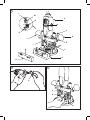
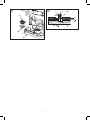
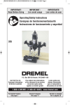
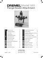
Model 335
Plunge Router Attachment
GB
6
CZ
Původním návodem k používání
62
D
Originalbetriebsanleitung
10
PL
Instrukcja obsługi
66
F
Notice originale
14
BG
Оригинално ръководство за експлоатация 71
I
Istruzioni originali
19
H
NL
Originele gebruiksaanwijzing
23
RO
DK
Original brugsanvisning
28
RUS
Одлинник руководства по эксплуатации 84
S
Bruksanvisning i original
32
EST
Algupärane kasutusjuhend
89
N
Original driftsinstruks
36
LT
Originali instrukcija
93
Izvirna navodila
97
FIN
Original instructions
Eredeti használati utasítás
75
Instrucţiuni de folosire originale
80
Alkuperäiset käyttö-/turvallisuusohjeet
40
SLO
E
Manual original
44
LV
Instrukcijām oriģinālvalodā
101
P
Manual original
49
HR
Originalne upute za rad
105
GR
Οδηγίες χρήσης
53
SRB
Оригинално упутство за рад
110
TR
Orijinal kullanım kılavuzu
58
SK
Pôvodný návod na použitie
114
Dremel Europe
The Netherlands
2610004523 190309
www.dremel.com
All Rights Reserved
1
L
FIG. 1
M
A
N
B
C
K
D
J
E
I
F
G
H
2
3
A
A
B
C
4B
4A
9.65 mm
9.65 mm
6.4 mm
3.2 mm
4.8 mm
612
615
640
650
652
2615061232
2615061532
2615064032
2615065032
2615065232
6.4 mm
7.5 mm
654
655
2615065432 26150655JA
A
B
C
D
A
5
8
B
X
A
B
C
X
6FIG. 6
9
x1
A
B
A
A
10
7
A
X
B
B
X
C
3
11
B
A
I
C
D
E
F
G
H
12
13
A
A
B
B
4
14
15
B
A
A
C
D
E
G
B
C
5
F
GB
GENERAL SAFETY INSTRUCTIONS
g.If devices are provided for the connection of dust extraction and
collection facilities, ensure these are connected and properly
used. Use of these devices can reduce dust related hazards.
h. Do not work materials containing asbestos (asbestos is
considered carcinogenic).
i.Take protective measures when during work dust can
develop that is harmful to one's health, combustible or
explosive (some dusts are considered carcinogenic); wear a dust
mask and work with dust/ chip extraction when connectable.
READ ALL INSTRUCTIONS.
Failure to follow all instructions
listed below may result in electric shock, fire and/or
serious injury. The term “power tool” in all of the warnings listed below
refers to your mains-operated (corded) power tool.
! WARNING
SAVE THESE INSTRUCTIONS
POWER TOOL USE AND CARE
WORK AREA
a.Do not force the power tool. Use the correct power tool for your
application. The correct power tool will do the job better and safer
at the rate for which it was designed.
b.Do not use the power tool if the switch does not switch it on and
off. Any power tool that cannot be controlled with the switch is
dangerous and must be repaired.
c.Disconnect the plug from the power source before making any
adjustments, changing accessories, or storing power tools. Such
preventive safety measures reduce the risk of starting the power
tool accidentally.
d.Store idle power tools out of the reach of children and do not
allow persons unfamiliar with the power tool or these instructions
to operate the power tool. Power tools are dangerous in the hands
of untrained users.
e.Maintain power tools. Check for misalignment or binding of
moving parts, breakage of parts and any other condition that may
affect the power tools operation. If damaged, have the power
tool repaired before use. Many accidents are caused by poorly
maintained power tools.
f.Keep cutting tools sharp and clean. Properly maintained cutting
tools with sharp cutting edges are less likely to bind and are easier
to control.
g.Use the power tool, accessories and tool bits etc., in accordance
with these instructions and in the manner intended for the
particular type of power tool, taking into account the working
conditions and the work to be performed. Use of the power tool
for operations different from those intended could result in a
hazardous situation.
a.Keep work area clean and well lit. Cluttered and dark areas invite
accidents.
b.Do not operate power tools in explosive atmospheres, such as
in the presence of flammable liquids, gases or dust. Power tools
create sparks which may ignite the dust or fumes.
c.Keep children and bystanders away while operating a power tool.
Distractions can cause you to lose control.
ELECTRICAL SAFETY
a.Power tool plugs must match the outlet. Never modify the plug in
any way. Do not use any adapter plugs with earthed (grounded)
power tools. Unmodified plugs and matching outlets will reduce
risk of electric shock.
b.Avoid body contact with earthed or grounded surfaces such as
pipes, radiators, ranges and refrigerators. There is an increased
risk of electric shock if your body is earthed or grounded.
c.Do not expose power tools to rain or wet conditions. Water
entering a power tool will increase the risk of electric shock.
d.Do not abuse the cord. Never use the cord for carrying, pulling or
unplugging the power tool. Keep cord away from heat, oil, sharp
edges or moving parts. Damaged or entangled cords increase the
risk of electric shock.
e.When operating a power tool outdoors, use an extension cord
suitable for outdoor use. Use of a cord suitable for outdoor use
reduces the risk of electric shock.
f. If operating a power tool in a damp location is unavoidable, use
an earth leakage circuit breaker. Use of an earth leakage circuit
breaker reduces the risk of electric shock.
SERVICE
a.Have your power tool serviced by a qualified repair person using
only identical replacement parts. This will ensure that the safety of
the power tool is maintained.
PERSONAL SAFETY
a.Stay alert, watch what you are doing and use common sense
when operating a power tool. Do not use a power tool while you
are tired or under the influence of drugs, alcohol or medication. A
moment of inattention while operating power tools may result in
serious personal injury.
Use safety equipment. Always wear eye protection.
b.
Safety equipment such as dust mask, non-skid safety
shoes, hard hat, or hearing protection used for
appropriate conditions will reduce personal injuries.
c.Avoid accidental starting. Ensure the switch is in the off position
before plugging in. Carrying power tools with your finger on the
switch or plugging in power tools that have the switch on invites
accidents.
d.Remove any adjusting key or wrench before switching the power
tool on. A wrench or a key left attached to a rotating part of the
power tool may result in personal injury.
e.Do not overreach. Keep proper footing and balance at all times.
This enables better control of the power tool in unexpected
situations.
f.Dress properly. Do not wear loose clothing or jewellery. Keep your
hair, clothing and gloves away from moving parts. Loose clothes,
jewellery or long hair can be caught in moving parts.
SAFETY INSTRUCTIONS FOR ROUTERS
GENERAL
•
•
T his tool should not be used by people under the age of 16 years.
Always disconnect plug from power source before making any
adjustment or changing any accessory.
•
se only accessories with an allowable speed matching at least
U
the highest no-load speed of the tool.
Do not use damaged or deformed router bits.
Only use sharp router bits.
Protect accessories from impact, shock and grease.
ACCESSORIES
•
•
•
BEFORE USE
•
6
A void damage that can be caused by screws, nails and other
elements in your workpiece; remove them before you start
working.
•
•
•
•
•
E
F
G
H
I
J
K
L
M
N
Always check that the supply voltage is the same as the voltage
indicated on the nameplate of the tool (tools with a rating of 230V
or 240V can also be connected to a 220V supply).
Clamp the workpiece in case it does not remain stationary from
its own weight.
Dust from material such as paint containing lead, some wood
species, minerals and metal may be harmful (contact with
or inhalation of the dust may cause allergic reactions and/or
respiratory diseases to the operator or bystanders); wear a dust
mask and work with a dust extraction device when connectable.
Follow the dust-related national requirements for the materials
you want to work with.
Be sure tool is switched off when plugging in.
ASSEMBLY
Assembling Plunge Router Attachment to
your Tool
DURING USE
•
•
•
•
•
•
•
ATTACHMENT FOR USE WITH DREMEL ROTARY TOOL MODELS 300,
395, 398, 400, 4000.
A lways keep the cord away from moving parts of the tool; direct
the cord to the rear, away from the tool.
Never use the tool when cord or base-plate (=protective guard) is
damaged; have it replaced by a qualified person.
Keep hands and fingers away from router bit when tool is
switched on.
In case of electrical or mechanical malfunction, immediately
switch off the tool and disconnect the plug.
In case the router bit is blocked, resulting in jerking forces on the
tool, immediately switch off the tool.
In case of current interruption or when the plug is accidentally
pulled out, immediately switch off the tool in order to prevent
uncontrolled restarting.
Do not apply so much pressure on the tool that it comes to a
standstill.
Disconnect the plug from the power source
before making any assembly adjustments
or changing accessories. Such preventive safety measures reduce
the risk of starting the tool accidentally.
! WARNING
1. Remove collet nut, then remove housing cap from your rotary
tool and set housing cap aside (Fig. 2). The housing cap must be
reinstalled when this attachment is not used. Once housing cap
has been removed, reassemble the collet nut.
See Figure 2:
A Housing Cap
ENVIRONMENT
2. Place tool into your router attachment with the shaft lock button
facing forward as shown (Fig. 3).
3. Screw mounting nut clockwise onto the threaded portion of
your Rotary Tool and securely tighten with the mounting wrench
provided.
DISPOSAL
The machine, accessories and packaging should be sorted for
environmental-friendly recycling.
See
A
B
C
ONLY FOR EC COUNTRIES
Do not dispose of power tools into household waste!
According the European Guideline 2002/96/EC for Waste
Electrical and Electronic Equipment and its implementation
into national right, power tools that are no longer usable
must be collected separately and disposed of in an
environmentally correct manner.
•
Figure 3:
Shaft Lock Button
Mounting Nut
Mounting Wrench
Operating Instructions
ATTENTION: This attachment will convert Dremel Rotary Tool to a
Plunge Router for freehand routing, edging, grooving, and circular cuts.
The router attachment comes assembled ready for freehand or pilot
bit routing.
Periodic cleaning and lubrication of guide posts will keep plunge action
smooth. Depress and lock plunge router and evenly apply a light
lubricant (i.e. petroleum jelly, cooking oil) to upper portion of guide posts.
APPLICATION ADVICE
•
•
•
Collet Nut Wrench Storage Area (Wrench not included)
Depth Scale (English/Metric)
Edge Guide
Circle Guide
Shaft Lock Button
Hand Grip (stationary)
Adjustment Nut, Lower
Depth Stop
Adjustment Nut, Upper
Release Button
se the appropriate router bits.
U
For cuts parallel with the side of your workpiece use a rip fence.
For making parallel cuts in a workpiece far from the edge:
–fasten a straight piece of wood on the workpiece by means
of 2 clamps;
–guide tool with base-plate along edge of wood which now
functions as a rip fence.
Protect yourself against the effects of vibration by maintaining
the tool and its accessories, keeping your hands warm, and
organizing your work patterns.
! WARNING
This Router Attachment is not intended for
use under a router or saw table.
Accessories specification
See Figure 4A.
Inserting the Router Bit
OPERATING CONTROLS
The router bits are held in the tool by a collet system. The bit may
be installed before or after the rotary tool is installed in the
attachment.
1. Depress and hold the shaft lock button while rotating the collet
nut and shaft. Continue to rotate the collet nut and shaft until the
lock engages and holds the shaft (Fig. 4).
See Figure 1:
A Dremel Rotary Tool
B Speed Control
C Mounting Wrench & Storage Area
D Hand Grip (turn to lock)
7
2. Use the wrench from your Dremel Rotary Tool and turn the collet
nut counterclockwise to loosen it.
3. Release the shaft lock button.
4. Insert the router bit into the collet as deep as possible to ensure
proper gripping of the bit and to minimize run out. Do not insert
the bit so far that bit flutes touch the collet or collet nut to avoid
chipping or cracking the bit.
NOTE: Never place the tool with bit protruding through base on
top of bench or work surface. Lay the tool on its side or retract
the bit before setting on bench or work surface. Protruding cutting
bit may cause tool to jump.
5. Re-engage the shaft lock button and tighten the collet nut; first by
hand, then using the wrench until bit is held securely.
9. Turn the lower adjustment nut up snug against the router frame.
See Figure 4B:
A Shaft Lock Button
B Collet Nut
C Collet Nut Wrench
D Base
When routing is complete, loosen the hand grip and return the router
to the top position.
NOTE: The upper adjustment nut must remain stationary when
tightening the lower adjustment nut.
10. Press the release button to select the 1st or 2nd routing depth
(Fig. 9).
NOTE: The adjustment of each routing depth should be checked with a
trial cut and re-adjusted as necessary.
See Figure 9:
A Release button
Feeding the Router
If the router is hard to control, heats up, runs very slowly or leaves an
imperfect cut, consider these causes:
• Wrong direction of feed – hard to control.
• Feeding too fast – overloads motor.
• Dull bit – overloads motor.
• Cut too large for one pass – overloads motor.
• Feeding too slow – leaves friction burns on the workpiece.
Feed smoothly and steadily (do not force). You will soon learn how the
router sounds and feels when it is working best.
Adjusting Routing Depth
NOTE: When making deep cuts, especially plunge cuts away from
the edge of the work-piece, it is recommended to make several
successive cuts progressively deeper using the depth adjustment and
depth scale rather than making one single deep cut.
The depth limiter can be adjusted for two depths.
1. Place your Dremel Rotary Tool and Router assembly on the
workpiece.
2. Turn the upper adjustment nut upward and turn the lower
adjustment nut down-ward so depth stop is free to move (Fig. 5).
Rate Of Feed
When routing or doing related work in wood and plastics, the best
finishes will result if the depth of cut and feed rate are regulated to
keep the motor operating at high speed.
Feed the router at a moderate rate. Soft materials require a faster feed
rate than hard materials.
The router may stall if improperly used or overloaded. Reduce the feed
rate to prevent possible damage to the tool. Always be sure the collet
nut is tightened securely before use. Always use router bits with the
shortest cutting length necessary to produce the desired cut. This will
minimize router bit runout and chatter.
See Figure 5:
A Depth-Stop
B Upper Adjustment Nut
C Lower Adjustment Nut
3. Loosen the locking hand grip (Fig. 6). Slowly lower the tool until
the router bit just touches the workpiece.
See Figure 6:
A Hand Grip
B Release Button
Edge Forming
When edge forming, always use piloted or bearing bits. The lower
portion of a pilot tipped bit is a shaft with no cutting edges. Bearing
guide bits have a ball bearing to pilot the bit.
The pilot slides along the edge of the work as the rotating blades
make the cut, making decorative edges. The edge on which the
pilot slides should be perfectly smooth since any irregularities are
transferred to the shaped surface.
When routing a workpiece that requires edge forming on the endgrain,
always rout the endgrain edge before routing the edges that follow the
grain. This minimizes the possibility of damage from any blowout at
the end of the endgrain.
4. Tighten the locking hand grip to lock the tool in place.
5. Press and hold the release button so depth stop touches the
router base.
1st Routing Depth
6. Turn the depth stop upwards so that measurement X equals the
first desired routing depth (Fig. 7).
NOTE: 1 turn equals .06" (1.5 mm)
See Figure 7:
A Depth Stop
B Upper Adjustment Nut
Router Feed Direction
The router spindle turns in a clockwise direction when viewed from
above. For best control and quality of cut, feed the tool into the
workpiece in the direction that the bit will tend to pull itself into the
wood. Incorrect feed direction will cause the bit to try and climb over
the wood.
Feed the tool in direction shown here. If cutting around the edge of a
square piece, move the tool in a counterclockwise direction. If routing
the inside surface as shown, move in a clockwise direction (Fig. 10).
NOTE: Feed direction is extremely important when using a pilot bit
freehand on the edge of a workpiece.
7. Turn the upper adjustment nut down snug against the router frame.
2nd Routing Depth
8. Turn the depth stop upwards so that measurement X equals the
second desired routing depth. Make sure upper adjustment nut
turns with the depth stop, so it rises away from router frame
(Fig. 8).
See Figure 8:
A Depth Stop
B Lower Adjustment Nut
8
See Figure 10:
A Router Feed direction
B Router End Grains First
C Bit Rotation
2. Use the finishing nail provided as a compass point. Set the circle
guide for the desired radius.
3. Place the nail through the hole in the guide and place the nail at
the center of the desired radius to be cut.
Assembling the Edge Guide
TEMPLATES
For edge guide use, assemble guide rods into tool holder assembly
and secure using (2) #10-24 square nuts and (2) guide rod knobs
(Fig. 11).
Square nut will slide in slots above the guide rods. Guide rod knobs
are assembled from the top through holes down through nuts, and
against the rods. Fasten edge guide to guide rods using edge guide
knobs, and hex head nuts.
Locate hex head nuts underneath edge guide and fasten with edge
guide knob on top surface of edge guide. Slide edge guide assembly
on guide rods as shown. Set edge guide at desired distance from
cutter and tighten edge guide knobs. (See Fig. 11)
Edge guide is used for shaping edges, cutting rabbets, dadoes,
mortise, tongues, grooves, slots, and chamfers. Remember to feed so
the cutter tends to pull the edge guide against the wood. A consistent
feed rate gives a smooth cut.
In general, several shallow cuts should be used when a deep groove is
desired. Maximum depth of cut will vary depending on material used.
Do not overfeed to an amount that the motor is noticeably slowed.
Using template patterns lets you duplicate designs or letters uniformly
time after time. This technique requires the use of a guide bushing.
See
A
B
C
D
E
F
G
H
I
GUIDE BUSHINGS
The guide bushing shown in (Fig. 14), is essentially a plate with a
collar which is inserted into the hole in base as shown, and secured
by threading a bushing plug on top of the guide bushing. The guide
bushing rides along the edge of the template while the router bit,
protruding below, cuts into the work.
See
A
B
C
Figure 14:
Bushing Plug
Guide Bushing
Base
ATTENTION: Be sure the thickness of the template is the same or
larger than the length of bushing protruding below the base.
Do not use a bit that may touch the inside of the collar. Select a bit
that is at least 2 mm less in diameter.
In addition, special templates are easily prepared for cutting repeated
patterns, special designs, inlays, and other applications. A template
pattern may be made of plywood, hardboard, metal or even plastic,
and the design can be cut with a router, jigsaw, or other suitable
cutting tool.
Remember that the pattern will have to be made to compensate
for the distance between the router bit and the guide bushing (the
“offset”), as the final workpiece will differ in size from the template
pattern by that amount, due to the bit position (Fig. 15).
Figure 11:
Depth Adjustment Screw
Guide Rod Knob
Square Nuts
Guide Rods
Edge Guide
Finishing Nail
Circle Guide
Hex Head Nuts
Edge Guide Knob
See
A
B
C
D
E
F
G
Edge Guide
Installation
1. Install the edge guide to the plunge router mounting blocks (Fig.
12).
See Figure 12:
A Mounting Blocks
B Edge Guide
Figure 15:
Router Bit
Collet Nut
Guide Bushing
Base
Template Pattern
Workpiece
Offset
FREEHAND ROUTING
Many effects are gained by using the router freehand with a small
diameter bit. Usually the craftsman pencils the outline or script he
desires onto the work and uses the pencil line as a guide.
2. Place parallel guide against work surface with router bit in
desired position.
3. Tighten thumbscrews.
SERVICE AND WARRANTY
Routing with Edge Guide
Slide the flattened side of the edge guide along the work surface.
This DREMEL product is guaranteed in accordance with statutory/
country-specific regulations; damage due to normal wear and tear,
overload or improper handling will be excluded from the guarantee.
Circle Guide
Routing Arcs and Circles
1. Remove the edge guide and attach the circle guide bracket to the
guide rods (Fig. 13).
In case of a complaint, send the tool undismantled together with proof
of purchase to your dealer.
See Figure 13:
A Finishing Nail
B Edge Guide
CONTACT DREMEL
For more information on the Dremel assortment, support and hotline,
go to www.dremel.com
Dremel Europe, P.O. Box 3267, 4800 DG Breda, The Netherlands
9