1
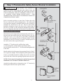
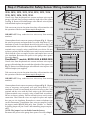
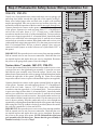
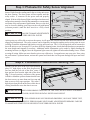
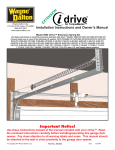
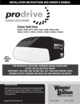
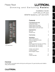
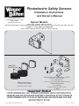
Photoelectric Safety Sensors
Installation Instructions
and Owner’s Manual
Wayne-Dalton Corp.
P.O. Box 67 Mt. Hope, OH 44660
(888) 827-3667
www.wayne-dalton.com
Opener Models:
Torsion idrive™ models: 3651-372, 3750-372.
Quantum™/Classicdrive™ models: 3012, 3014, 3016, 3018, 3212, 3213, 3214, 3312, 3313, 3314, 3316, 3412, 3414, 3512, 3514.
DoorMaster™ models: BDOR-2000 & BIRW-2000
idrive™ models: 3660-372, 3661-372, 3662-372, 3760-372, 3751-372.
WIRES ARE
PRE-ATTACHED
Photoelectric Sensors Hardware: 297218
(2) 5/16 x 1-1/2” Lag Screws
(2) 1” Flat Head Nails
(2) 1/4-20 x 1/2” Carriage Bolts, Washers & Nuts
(2) Wall Mounting Brackets
(2) “U” Brackets
(1) Power Cord Clip (adhesive back)
(1) Jumper
Photoelectric Sensors
(1) Sender w/Wire: 260600
(1) Receiver w/Wire: 260597
Important Notice!
DOOR OPENER WILL NOT OPERATE PROPERLY UNTIL PHOTOELECTRIC
SENSORS ARE INSTALLED AND PROPERLY ADJUSTED! DO NOT OPERATE
DOOR OPENER UNTIL IT IS FULLY INSTALLED, ADJUSTED AND YOU ARE
INSTRUCTED TO DO SO!
© Copyright 2003 Wayne-Dalton Corp.
Part No: 306736
New
9/4/2003
Table of Contents
Important Safety Instructions For Installation And Use ○ ○ ○ ○ ○ ○ ○ ○ ○ ○ ○ ○ 2.
Bracket Installation ○ ○ ○ ○ ○ ○ ○ ○ ○ ○ ○ ○ ○ ○ ○ ○ ○ ○ ○ ○ ○ ○ ○ ○ ○ ○ ○ ○ ○ ○ ○ ○ ○ ○ ○ ○ ○ ○ 3.
Wiring Installation “Quantum™/Classicdrive™” ○ ○ ○ ○ ○ ○ ○ ○ ○ ○ ○ ○ ○ ○ ○ ○ ○ 4.
Wiring Installation “DoorMaster™” ○ ○ ○ ○ ○ ○ ○ ○ ○ ○ ○ ○ ○ ○ ○ ○ ○ ○ ○ ○ ○ ○ ○ ○ ○ ○ ○ ○ 4.
Wiring Installation “idrive™” ○ ○ ○ ○ ○ ○ ○ ○ ○ ○ ○ ○ ○ ○ ○ ○ ○ ○ ○ ○ ○ ○ ○ ○ ○ ○ ○ ○ ○ ○ ○ ○ 5.
Wiring Installation “Torsion idrive™” ○ ○ ○ ○ ○ ○ ○ ○ ○ ○ ○ ○ ○ ○ ○ ○ ○ ○ ○ ○ ○ ○ ○ ○ ○ ○ 5.
Photoelectric Safety Sensor Alignment ○ ○ ○ ○ ○ ○ ○ ○ ○ ○ ○ ○ ○ ○ ○ ○ ○ ○ ○ ○ ○ ○ ○ ○ 6.
Photoelectric Obstruction Sensing Test ○ ○ ○ ○ ○ ○ ○ ○ ○ ○ ○ ○ ○ ○ ○ ○ ○ ○ ○ ○ ○ ○ ○ 6.
Important Safety Instructions ○ ○ ○ ○ ○ ○ ○ ○ ○ ○ ○ ○ ○ ○ ○ ○ ○ ○ ○ ○ ○ ○ ○ ○ ○ ○ ○ ○ ○ ○ ○ 7.
Warranty ○ ○ ○ ○ ○ ○ ○ ○ ○ ○ ○ ○ ○ ○ ○ ○ ○ ○ ○ ○ ○ ○ ○ ○ ○ ○ ○ ○ ○ ○ ○ ○ ○ ○ ○ ○ ○ ○ ○ ○ ○ ○ ○ ○ ○ ○ ○ 7.
Customer Service Number ○ ○ ○ ○ ○ ○ ○ ○ ○ ○ ○ ○ ○ ○ ○ ○ ○ ○ ○ ○ ○ ○ ○ ○ ○ ○ ○ ○ ○ ○ ○ ○ ○ 7.
THIS IS THE SAFETY ALERT SYMBOL. IT IS USED TO ALERT YOU TO POTENTIAL
PERSONAL INJURY HAZARDS. OBEY ALL SAFETY MESSAGES THAT FOLLOW THIS
SYMBOL TO AVOID POSSIBLE INJURY OR DEATH.
WARNING DISCONNECT ALL POWER FROM GARAGE DOOR OPENER BEFORE SERVICING
OR INSTALLING ACCESSORY PRODUCTS.
IMPORTANT SAFETY INSTRUCTIONS FOR
INSTALLATION AND USE
READ AND FOLLOW ALL
INSTALLATION INSTRUCTIONS.
AFTER INSTALLING OPENER,
THE DOOR MUST REVERSE
WHEN IT CONTACTS A 1 INCH
HIGH SOLID TEST OBJECT ON
THE FLOOR.
DO NOT USE SENSITIVITY
ADJUSTMENT TO COMPENSATE
FOR A POORLY OPERATING DOOR.
THIS WILL INTERFERE WITH THE
PROPER OPERATION OF THE
SAFETY REVERSE MECHANISM.
OPEN DOOR MUST NOT CLOSE
AND CLOSING DOOR MUST
OPEN IF PHOTOELECTRIC
SYSTEM IS OBSTRUCTED BY
6”X HIGH OBJECT, USING TEST
PROCEDURE DESCRIBED IN
STEP 4.
DO NOT CONNECT OPENER TO
ELECTRICAL OUTLET UNTIL
INSTRUCTED TO DO SO.
DO NOT WEAR RINGS, WATCHES
OR LOOSE CLOTHING WHEN
INSTALLING OR SERVICING A
GARAGE DOOR SYSTEM. USE A
STURDY, NONMETALLIC STEP
LADDER AND WEAR EYE
PROTECTION.
INSTALLATION AND WIRING MUST
COMPLY WITH LOCAL BUILDING
AND ELECTRICAL CODES.
CONNECT THE POWER CORD TO A
PROPERLY GROUNDED OUTLET.
DO NOT REMOVE ROUND GROUND
PIN FROM POWER CORD.
2
Step 1: Photoelectric Safety Sensor Bracket Installation
WARNING
DISCONNECT ALL POWER TO
GARAGE DOOR OPENER BEFORE SERVICING OR
INSTALLING ACCESSORIES OR PHOTOELECTRIC
SAFETY SENSORS. FOR ALL OPENERS, UNPLUG 120 V
AC POWER CORD FROM RECEPTACLE.
FOR
DOORMASTER, ALSO UNPLUG TELEPHONE CORD TYPE
COMMUNICATIONS CABLE.
Select a mounting position, no more than 5 inches above the
floor to center line of wall mounting bracket. The sending and
receiving units should be mounted inside the door opening to
minimize any interference by the sun. However, the sensors
should be mounted as close to the door track or inside edge of
the door as possible to offer maximum entrapment protection.
It is very important that both wall brackets be mounted at the
same height for proper alignment.
“U” BRACKETS
WALL MOUNTING
BRACKETS
NUT
(1) 5/16 X 1-1/2”
LAG SCREW
The brackets may be temporarily mounted to the jamb with a 1” WASHER
flat head nail (provided) using the small hole above the slot.
Using two 5/16 x 1-1/2” lag screws (provided), permanently
mount the wall mounting brackets to both door jambs. In some
installations it may be necessary to attach a wooden spacer to
(1)1/4-20 X 1/2”
the wall to achieve the required clearance.
CARRIAGE BOLT
Attach the “U” brackets to the wall brackets with a
1/4-20 carriage bolt, washer and nut (provided). Insert
the bolt from the inside of the “U” bracket and hand tighten only
at this time.
NAIL
5”
TAB HOLES
TOP & BOTTOM
Identify which side of the garage door opening (if any) is “likely”
to be exposed to sunlight. Since sunlight may affect photoelectric
sensors, you should mount the sending unit (not the receiving
unit) on the side of the door opening exposed most to the sun.
TABS
TOP & BOTTOM
NOTE: If wires must be lengthened or spliced into prewired
installation, use wire nuts or suitable connectors.
Attach the sending and receiving units to the “U” brackets by
inserting their tabs into the respective holes.
RECEIVING UNIT
SENDING
UNIT
(NO LED)
LED ALIGNMENT
LIGHT
3
Step 2: Photoelectric Safety Sensor Wiring Installation For:
Quantum™/Classicdrive™ models: 3012, 3014,
3016, 3018, 3212, 3213, 3214, 3312, 3313, 3314,
3316, 3412, 3414, 3512, 3514.
Uncoil wires from the photoelectric sensors and route wires up the
garage walls and along ceiling towards the right side of the opener
(see Fig. 1). Route wires behind torque tube and tack wires in place
with insulated staples (not supplied).
Take care to run wires in a location where they will not interfere with
the operation of the door and do not staple through wire.
IMPORTANT! Keep sender/receiver wires away from moving
members.
Connect photoelectric sensors to opener per diagram (Fig. 1). Shorten
the wires as necessary and separate the wire ends. Strip about 1/2” of
insulation off each wire and attach the solid color wires to the COM
terminal and the wires with a black stripe to the OBS terminal. Tighten
terminal screws securely, using a small blade screw driver. Be sure
to observe polarity. Pull on external wires to test for secure connection.
Check that the wires are stapled in place and staples have not cut
wire insulation. Reconnect the power to the garage door opener.
Proceed to Step 3.
Opener
FIG. 1 Wire Routing
Black striped wires
(OBS terminal)
Sender
wires
Solid color wire
(COM terminal)
Receiver
wires
Solid color wire
(COM terminal)
Quantum™/Classicdrive™
DoorMaster™ models: BDOR-2000 & BIRW-2000
Uncoil wires from the photoelectric sensors and route wires up the
garage walls and along door towards the right side of the opener (see
Fig. 2). Route wires behind torque tube and tack wires in place with
insulated staples (not supplied).
Take care to run wires in a location where they will not interfere with
the operation of the door and do not staple through wire.
FIG. 2 Wire Routing
IMPORTANT! Keep sender/receiver wires away from moving NOTE: If wires must be lengthened or spliced into
members.
prewired installation, use wire nuts or a suitable
connector. Pay attention to polarity.
Connect photoelectric sensors to opener per diagram (Fig. 2). Shorten
Sender wires
Black striped wire
wires as necessary and separate wire ends. Strip about 1/2” of (OBS terminal)
Solid color wires
insulation off each wire and attach the solid color wires to the COM
(COM terminal)
terminal and the wires with the black stripe to the OBS terminal.
Receiver
Tighten terminal screws securely, using a small blade screwdriver.
wires
Be sure to observe polarity. Pull on external wires to test for secure
Jumper
connection. Check that the wires are stapled in place and staples
(Model: BDORhave not cut wire insulation. Remember to connect telephone type
2000 only)
cord for Doormaster™ installation. Once wires are connected, switch
the jumper (model BDOR-2000 only) from “Disable” to “Enable”
Black striped wire
(OBS terminal)
by pulling jumper off pins 2 and 3 and reinstalling jumper on pins 1
and 2.
Right endcap
NOTE: The jumper is set to disable from the factory.
DoorMaster™
Reconnect the power to the garage door opener. Proceed to Step 3.
4
Step 2: Photoelectric Safety Sensor Wiring Installation For:
idrive™ models: 3660-372, 3661-372, 3662-372,
3760-372, 3751-372.
Uncoil wires from photoelectric sensors and route wires up garage wall
and along door header towards the right side of the opener (see Fig. 3 ).
Route wires behind torque tube and tack wires in place with insulated
staples (not supplied).Take care to run wires in a location where they will
not interfere with the operation of the door and do not staple through wire.
Connect photoelectric sensors to the opener terminal block on right side
of the opener. Separate wire ends and strip about 1/2” of insulation off
FIG. 3 Wire Routing
each of the wire ends. Insert a 3/32” (2.5mm) max. width flathead
Insert wires
screwdriver into the lower hole #1 of the terminal block. Twist screwdriver into upper
Jumper
to open wire clamp in upper hole #1 of terminal block. Insert both sender hole #1
Insert wires installed
and receiver solid white wires into upper hole #1 until the wires bottom
into upper
out and release screwdriver tension. Insert both sender and receiver wires
hole #2
(white with black stripe) into upper hole #2 by the same process on lower
hole #2 of terminal block. Be sure to observe polarity. Once wires are
connected, install jumper on to the left most set of pins labeled “PE” of
the opener.
Jumper
IMPORTANT! Keep sender/receiver wires away from moving members. Insert screw Insert screw
driver into lower
Pull on external wires to test for secure connection. Check that the wires driver into
hole #2
are stapled in place and staples have not cut wire insulation. Reconnect lower hole #1
the power to the garage door opener. Proceed to Step 3.
Torsion idrive™ models: 3651-372, 3750-372.
To locate the terminal block for the infrared sensor sender/receiver wires,
you must first move the right hand gear assembly. Loosen the set screw
and slide the gear assembly away from the opener. Uncoil wires from
photoelectric sensors and route wires up garage wall and along door header
towards the right side of the opener (see Fig. 4). Route wires behind
torque tube and tack wires in place with insulated staples (not supplied).
Connect photoelectric sensors to the opener terminal block on right side
of the opener. Separate wire ends and strip about 1/2” of insulation off
each of the wire ends. Insert a 3/32” (2.5mm) max. width flathead
screwdriver into the upper hole #1 of terminal block. Twist screwdriver
to open wire clamp in lower hole #1 of terminal block. Insert both sender
and receiver solid white wires into lower hole #1 until the wires bottom
out and then release screwdriver tension. Insert both sender and receiver
wires (white with black stripe) into lower hole #2 by the same process. Be
sure to observe polarity. Keep the sender and receiver wires straight and
organized by wrapping them around the backside of the opener and securing
them using the cord clip (adhesive backed) provided.(Insure the surface
the cord clip is attached to is clean and oil free.
IMPORTANT! Keep sender/receiver wires away from moving members.
Pull on external wires to test for secure connection. Check that the wires
are stapled in place and staples have not cut wire insulation. Reconnect
the power to the garage door opener. NOTE: Reinstall the right hand
gear assembly onto the drive gear. Ensure that the gear assembly is
installed correctly. Proceed to Step 3.
5
Pins
labeled
“PE”
White wires
with black
stripe
Solid white
wires
idrive™
FIG. 4 Wire Routing
Right hand
gear assembly
Insert screwdriver
into upper holes
Set screw
Insert wires
into lower holes
Cord clip
Torsion idrive™
Step 3: Photoelectric Safety Sensor Alignment
IMPORTANT! - This infrared safety sensor sends an invisible
beam of light from the sending unit to the receiving unit across
IN
the door opening. The door opener will not operate until the
safety sensor is connected to the power unit and properly
aligned. If the invisible beam of light is misaligned or obstructed,
an open door cannot be closed by the transmitter or a momentary
activation of the wall mounted push button. However, the door
OUT
may be closed by holding your finger on the wall push button
(constant pressure) until the door travels to a fully closed
position.
WARNING FAILURE TO MAKE ADJUSTMENTS
FIG.5
IN
1/4-20 Carriage bolts
Top View
Align In Center
(In/Out)
OUT
FIG.6
For this adjustment bend
bracket at wall mount
Top view
Align in Center
COULD RESULT IN SEVERE OR FATAL INJURY.
At this point you will be able to activate the opener; it will open, but will not close the door unless the sensors are
aligned and unobstructed. The safety sensors can be aligned by moving the sending and receiving units in or out
(see Fig. 5) until the alignment light on the receiving unit comes on. The 1/4-20 carriage bolt can be loosened to
move the unit in or out, as required. If you have difficulty aligning beams, check that both brackets are mounted at
the same height and remount if necessary. Additional minor adjustments can be made by lightly bending the
mounting brackets (see Fig. 6).Once the alignment light comes on, tighten all bolts and mounting screws. Finish
securing all wiring. Make sure not to break or pierce any of the wires. Loop and secure any extra wire. Now, using
the wall station’s up/down button, activate the opener and check that it will operate through full open and close
cycles.
Step 4: Photoelectric Obstruction Sensing Test
Starting with the door in the fully open position,
place a 6” high object on the floor progressively
one foot from the left side of the door, center of
door and one foot from the right side of the door.
(Fig. 7) In each position, activation of the opener
with the wallstation up/down button should cause
the door to move no more than one foot, stop and
then reverse to fully open position. The same 6”
high object when placed on the floor, while door is
closing, should also cause the door to reverse.
FIG. 7
6”
12”
12”
WARNING WHEN PERFORMING THIS PART OF THE TEST, DO NOT PLACE YOURSELF
UNDER DESCENDING DOOR, OR SEVERE OR FATAL INJURY MAY RESULT.
WARNING
IF THE OPENER DOES NOT RESPOND PROPERLY, OR FAILS THESE TEST,
HAVE A QUALIFIED SERVICE PERSON MAKE NECESSARY ADJUSTMENTS/REPAIRS. FAILURE
TO MAKE ADJUSTMENTS COULD RESULT IN SEVERE OR FATAL INJURY.
6
IMPORTANT SAFETY INSTRUCTIONS
WARNING
TO REDUCE THE RISK OF SEVERE INJURY OR DEATH: Please thoroughly read
safety rules on Page 2 and the following operating instructions. Operate only when opener is properly adjusted and
the door is visible and unobstructed.
Never let children operate or play with
Always keep moving door insight and keep
door controls. Keep remote control away
people and objects away from the door
from children
until it is completely closed. NO ONE
Test door opener monthly. Open garage
SHOULD CROSS THE PATH OF THE
door MUST NOT close and closing door
MOVING DOOR.
MUST open if photoelectric obstruction
sensors system is obstructed by 6” high
Use the emergency release only when the
object, using test procedure described in
door is closed. Use caution when using
Step 4. If opener fails this test, disconnect
this release with door open. Weak or
immediately and call for technical support.
broken springs may cause the door to fall
Malfunctioning opener can cause severe
rapidly, causing serious injury or death.
injury or death.
Test door opener monthly. The garage door
MUST reverse on contact with a 1-1/2 inch
KEEP GARAGE DOORS PROPERLY
high object (or a 2 x 4 board laid flat) on
BALANCED. See owner’s manual. An
the floor. On Quantum™ openers, if
improperly balanced door could cause
adjusting either the force or the limit of
severe injury or death. Have a qualified
travel, retest the door opener. Failure to
service person make repairs to cables,
adjust the opener properly could cause
spring assemblies and other hardware.
severe injury or death.
Photoelectric Safety Sensors
90-DAY LIMITED WARRANTY
The Manufacturer warrants that the PHOTOELECTRIC SAFETY SENSORS will be free from defects in materials and workmanship including electronic components for
a period of 90-DAYS from the date of installation, provided it is properly installed, maintained and cared for under specified use and service.
This Warranty extends to the original homeowner, providing the PHOTOELECTRIC SAFETY SENSORS are installed in his/her place of primary residence. It is not
transferable. The warranty applies to residential property only and is not valid on commercial or rental property.
NO EMPLOYEE, DISTRIBUTOR, OR REPRESENTATIVE IS AUTHORIZED TO CHANGE THE FOREGOING WARRANTIES IN ANY WAY OR GRANT ANY
OTHER WARRANTY ON BEHALF OF MANUFACTURER.
The Manufacturer shall not be responsible for any damage resulting to or caused by its products by reason of installation, improper storage, unauthorized service,
alteration of products, neglect or abuse, any acts of nature beyond Manufacturer’s control (such as, but not limited to, lightning, power surges, water damage, etc.), or
attempt to use the products for other than the customary usage or for their intended purposes. The above warranty does not cover normal wear or any damage beyond
Manufacturer’s control or replacement labor.
THIS WARRANTY COVERS A CONSUMER PRODUCT AS DEFINED BY THE MAGNUSON-MOSS WARRANTY ACT. NO WARRANTIES, EXPRESSED OR
IMPLIED, (INCLUDING, BUT NOT LIMITED TO, THE WARRANTY OF MERCHANTABILITY OR FITNESS FOR A PARTICULAR PURPOSE), SHALL EXTEND
BEYOND THE APPLICABLE TIME PERIOD STATED IN BOLD FACE TYPE ABOVE.
Claims for defects in material and workmanship covered by this warranty shall be made in writing to the dealer from whom the product was purchased within the warranty
period. Manufacturer may either send a service representative or have the product returned to the Manufacturer at Buyer’s expense for inspection. If judged by
Manufacturer to be defective in material or workmanship, the product will be replaced or repaired at the option of the Manufacturer, free from all charges except
authorized transportation and replacement labor.
THE REMEDIES OF BUYER SET FORTH HEREIN ARE EXCLUSIVE AND ARE IN LIEU OF ALL OTHER REMEDIES, THE LIABILITY OF MANUFACTURER,
WHETHER IN CONTACT, TORT, UNDER ANY WARRANTY OR OTHERWISE, SHALL NOT EXTEND BEYOND ITS OBLIGATION TO REPAIR OR REPLACE,
AT ITS OPTION, ANY PRODUCT OR PART FOUND BY MANUFACTURER TO BE DEFECTIVE IN MATERIAL OR WORK SHALL NOT BE RESPONSIBLE FOR
ANY DIRECT, INDIRECT, SPECIAL OR CONSEQUENTIAL DAMAGES OF ANY NATURE.
This Warranty gives you specific legal rights and you may have other rights, which may vary from state to state. However, some states do not allow limitation on how long
an implied warranty lasts or the exclusion or limitation of incidental or consequential damages so the above limitations or exclusions may not apply to you.
© Copyright Wayne-Dalton Corp. 2003
Questions??
For quick answers and helpful advise, call
Wayne-Dalton Customer Service
(888) 827-3667
7