1
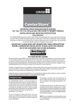
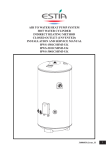
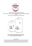
FEB-20E UK ECOPLUS
USER INSTRUCTIONS
AND
TECHNICAL INSTRUCTIONS
CONTENTS
Section
Page
1
USERS INSTRUCTIONS
3
2
GENERAL SPECIFICATIONS
6
3
TECHNICAL DATA
9
4
GENERAL INSTALLATION REQUIREMENTS
10
5
INSTALLATION INSTRUCTIONS
14
6
COMMISSIONING INSTRUCTIONS
17
7
ROUTINE SERVING INSTRUCTIONS
19
8
WIRING DIAGRAMS
21
9
FAULT FINDING
22
2
1.- USERS INSTRUCTIONS
1.1.- GAS SAFETY (INSTALLATION AND USE) REGULATIONS 1996 (AS AMENDED)
It is the law that all gas appliances are installed by a registered person, in accordance with the above regulations. Failure to install appliances correctly could lead to prosecution. It is in your own interest, and that of
safety, to ensure that the law is complied with.
WARNING: It is essential that the appliance is correctly earthed. An electricity supply of 230 V 50 Hz is
required, fused at 3 Amp.
Read these instructions carefully before attempting to operate the appliance. Comply with all applicable
warnings. Do not interfere with any sealed components, and use the appliance only in accordance with these
instructions.
1.2.- INTRODUCTION
The Fagor FEB-20E is a wall hung, room sealed, fan assisted, microprocessor controlled, fully modulating
gas combination boiler for providing both central heating and domestic hot water. The maximum heat output
in either heating or hot water mode is 23.7kW and priority is always given to the supply of hot water.
1.3.- PRELIMINARY WARNINGS
Check all of the gas pipe joints and make sure that gas reaches the boiler (with the gas cock turned on)
Make sure that the central heating circuit is completely full and vented. The pressure gauge should indicate
a pressure of between 0.75 and 1 bar with domestic cold water in the central heating circuit.
Make sure that the boiler is connected to the correct electricity voltage.
Make sure that the air intake and the combustion products outlet are not blocked.
CONTROL PANEL.
1.- Programmable timer
6
7
8
9
2.- Heating temperature and pressure
gauge
3.- Central heating temperature selector
1
12
40
60
20
9
3
80
100
0
120
0
4
4.- Main control switch
6
3
bar
2
1
5.- D.H.W. temperature selector
6.- Green neon light (boiler ready)
FEB-20E
1
2
7.- Orange neon light (burner functioning)
3
4
5
8.- Red neon light (boiler locked out)
1.4.- DOMESTIC HOT WATER SERVICE
To turn on the boiler turn the main control switch to the summer
setting. The boiler is then ready to supply D.H.W. on demand.
Whenever you turn on any hot tap the boiler automatically turns
on by firing up the burner. By means of the D.H.W. temperature
selector knob, any water temperature of between 35 and 60°C
may be selected.
3
Position:
min.
max
1.5.- HOT WATER AND CENTRAL
HEATING SERVICE
Turn the main control switch to the winter setting.
The burner will automatically fire up. By means of the central heating temperature selector control knob,any water temperature of
between 60 and 85°C may be selected. The boiler will remain on
until the temperature selected on the room thermostat or on the
boiler itself is reached.
Whenever there is a demand for D.H.W. from the central heating
setting, the boiler is ready to supply it giving priority to the D.H.W,
with the central heating on standby until the D.H.W. demand cease
Position:
min.
max
GENERAL GUIDANCE NOTES ON HOT WATER DELIVERY
This boiler has a temperature modulation system to control the hot water delivery temperature. However
there are certain circumstances which can “cheat” the system causing a wide variation of temperature at the
outlet. These notes are designed to help the user obtain the best possible performance from the boiler and
avoid situations which could result in unsatisfactory performance.
-
The boiler can theoretically supply more than one outlet simultaneously However in practice the tap which
is nearest will receive the most hot water. If the shower is in use and a kitchen tap is opened virtually all
the hot water will be diverted to the kitchen as it offers the least resistance.
-
If an outlet is too restrictive it will slow down the flow rate and increase the temperature. For example the
shower - ensure the head is free from blockages caused by scale.
-
Due to the restrictive nature of simple mixer showers it is wise to turn the temperature selector down on
the boiler before using the shower.
-
If a tap or shower head is too restrictive due to a fault or blockage, the flow rate will be reduced to below
the rate at which the boiler is able to modulate resulting in a wide swing in temperatures. Either fix the
restriction or turn the temperature selector on the boiler down.
-
Caution: The boiler can produce water at over 80°°C when in central heating mode. If you run a hot
tap when the boiler has been heating the radiators, the initial flow through the hot tap could be
very hot. DO NOT PLACE YOUR HANDS under the tap or use the shower until this initial flow has
passed.
-
Allow time (30 seconds) for the temperature to stabilise after making an adjustment at the tap before making further adjustments.
TURNING THE BOILER OFF
Turn the main control switch to the O setting.
Turn off the gas supply to the boiler
USING THE PROGRAMMABLE TIMER
1. To set correct time rotate minute hand until arrowhead aligns with correct time.
2. To set on/off times move all tappets between ‘on’ and ‘off’ times
required to outer position. is to set ‘on’ at 8am and off at 11am
move all tappets between 8 and 11 to outer position.
3. Set as many on/off times as required within a 24 hour period in
a similar manner to step 2.
1
12
9
3
6
12
34
4. Manual override switch: This has 3 positions.
- In position I (uppermost) the timeswitch is permanently ‘on’
regardless of tappet positions.
- In the middle position the timeswitch is operating on timed control and will only switch ‘on’ and ‘off’ as
determined by tappet positions.
- In position O (lowest) the timeswitch is permanently off irrespective of tappet positions
4
APPLIANCE SAFETY LOCK-OUT
This boiler has a cut-out indicator built in to it. Whenever a malfunction is detected in the ignition of the boiler, the boiler switches off automatically and the cut-out indicator lights up (red indicator light) To reset the boiler press the restart switch. The red indicator light should go out. IMPORTANT: Whenever the boiler has been
left idle for any length of time, or when a new gas bottle is installed (propane models), the appliance may
switch off due to the presence of air in the pipes. In cases such as these, repeat the ignition operation until
all of the air has been vented from the system.
FROST PROTECTION
Providing the boiler power supply and gas supply is connected and the main control switch is in the summer
setting the boiler will automatically fire on minimum setting when near freezing conditions are detected. When
the temperature in the system reaches 30°C it will switch off. For winter storage see notes at the end of this
section.
ANTI PUMP SEIZURE DEVICE
When central heating in not being used, but the boiler is in the summer setting (for domestic hot water only)
the pump will automatically run for three minutes every 24 hours to prevent it seizing. If the appliance has
been shut down with the gas and electrical supply switched off for a period, this device will not work. The
pump may be found to have jammed when the appliance is switched back on. If so, refer to “Routine
Servicing”page 19 .
PRESSURE GAUGE
The pressure gauge should indicate approximately 1 bar. If the pressure is seen to decrease over a period of
time there is a water leak. Consult your installer or service engineer.
ROUTINE SERVICING
To ensure continued safe and efficient operation of the appliance it is recommended that it is checked and
serviced as necessary at regular intervals. The frequency of servicing will depend upon the particular installation conditions and usage but in general once a year should be regarded as a minimum even if only occasional usage has occurred. It is the law that any service work MUST be carried out by a registered engineer
such as CORGI registered personnel.
SAFETY
It is essential that these instructions are strictly followed for the safe and economical operation of this appliance. The appliance is a fan-assisted balanced flue gas boiler and therefore the flue terminal MUST NOT BE
OBSTRUCTED under any circumstances. If it is damaged, turn off the appliance and consult your installer,
or service engineer. If it is known or suspected that a fault exists on the appliance it MUST NOT be used until
the fault has been rectified by a competent person.
PRECAUTIONS AGAINST FREEZING DURING WINTER STORAGE
During cold periods and if the boiler is situated in a place exposed to frosts, the D.H.W. circuit must be drained
down as follows:
- Turn off the cold water Supply
- Open all the hot water outlet taps on the installation (at least one tap should
be found at a level lower than the heater).
- Release the drain plug (shown opposite) which can be seen from under the
boiler.
- When the operation is finished, close the hot water outlet taps and replace
the drain plug.
- To put the boiler back into service, open the cold water inlet tap.
NOTE: In a Caravan Holiday Home installation there may be a drain cock on
the cold inlet under the van which may be used instead of the drain plug on the boiler.
NOTE: It is not necessary to drain the heating circuit if the heating circuit has been filled with anti-freeze.
5
2.- GENERAL SPECIFICATIONS
The Fagor FEB-20E is a wall hung, room sealed, fan assisted, microprocessor controlled fully modulating gas
combination boiler for providing both central heating and domestic hot water. It is particularly suitable for
Caravan Holiday Home and Park Home use. Maximum heat output in either heating or hot water mode is
23.7.kW (80.840 Btu/h), and priority is always given to the supply of hot water.
The appliance is supplied with a standard concentric air/flue duct and wall terminal, however additional
elbows, extension kits, vertical flue kit, or twin pipe flue kits are available as optional extras.
The appliance is intended for use with sealed central heating systems and is supplied for use with propane
gas.
The appliance is supplied fully assembled and includes the following principle components:
Burner with stainless steel flamestrips.
Copper heat exchanger.
Induced draught fan for the extraction of combustion products and induction of combustion air.
Modulating gas valve with double safety valves
Circulation pump with manual anti-seizure device and speed selector.
Central heating expansion vessel.
Differential air pressure switch - only allows the boiler to ignite if there is a sufficient supply of air reaching
the burner for satisfactory combustion performance, switching off the boiler in the event of fan failure or
obstruction in either the air inlet or flue products outlet ducts.
Thermistors (NTC) - There are two thermistors fitted for automatic control of the domestic hot water and the
central heating flow temperature.
Safety thermostat for protecting the boiler against any possible overheating by switching off the electricity
supply which in turn cuts off the gas supply. It is reset manually.
Electronic controls, incorporating the following features:
Temperature selection for central heating from between 60 to 85°C.
Temperature selection for domestic hot water from between 35 to 60°C.
Continuous modulation of the gas valve.
Flame control by ionisation
Ignition control
Anti-frost control in the central heating circuit.
Anti - seizure of the pump.
6
1
11
2
3
4
12
5
6
13
14
15
7
16
8
9
17
10
18
Principal components
1. Back Plate
2. Automatic Air Vent
3. Air pressure switch
4. Heating Thermistor
5. High limit stat
6. Ionisation electrode
7. Main Burner
8. Circulation Pump
9. Flow switch
10. Pressure relief valve
11. Fan
12. Heat Exchanger
13. Combustion Chamber
14. Expansion Vessel
15. Ignition electrode
16. Domestic Hot Water Thermistor
17. Gas Valve
18. Electronics Box
7
Schematic diagram- Hydraulic circuit
29
1.- Heat exchanger
31
30
27
2.- Ignition Electrode
1
3.- Detection electrode
5.- Burner
26
6.- Injector Manifold
2
25
7.- D.H.W Thermistor
24
5
8.- Burner pressure nipple
3
9.- Gas valve
23
6
10.- Inlet pressure nipple
11.- Gas inlet
7
13. D.H.W outlet
22
8
16
14.- Heating flow
16.- Flow switch
9
17.- Water filter
21
20 19 18
18.- Cold water inlet
19.- By-pass
10
17
14
13
11
3
2
25.- Expansion vessel
20.- Heating return
26.- Heating Thermistor
21.- Pressure relief valve
27.- Automatic air vent
22.- Circulation pump
29.- Air pressure switch
23.- High limit thermostat
30.- Fan
24.- Expansion vessel air valve
31.- Sealed air box
APPLIANCE Dimensions and connection details
440
=
100
60
=
6
25
36
156
111
5
4
800
1. 1/2” BPS Gas inlet
2. 1/2” BPS D.H.W. outlet
40
60
20
0
80
10 0
120
4
0
3
bar
2
1
3. 3/4” BPS Central heating flow
=
5
98
=
4
3
56
56
4. 1/2” BPS Domestic cold water inlet
2
1
98
111
5. 3/4” BPS Central heating return
317
6. Pressure relief valve outlet
8
1
3.- TECHNICAL DATA
Model
Category
Type
Maximum
Output
Central Heating (C.H) Output
Minimum
Output
Maximum
Output
Domestic Hot Water (D.H.W.) Output
Minimum
Output
Qn max.
Qn min.
Central Heating Nominal Heat Input (Hi) and D.H.W.
Nominal Heat input (Hi)
kW
kcal/h
kW
kcal/h
kW
kcal/h
kW
kcal/h
kW
kW
D.H.W. Flow Rate at 25º C Temp Rise (l/min)
D.H.W. Nominal Flow (l/min)
10
Minimum Flow Rate Required to Activate D.H.W. Mode (l/min)
Maximum
C.H.
Operating Pressure (bar)
Maximum
D.H.W.
Minimum
D.H.W.
Expansion Vessel Capacity (l)
Central Heating
Temperature Selection Range (ºC)
D.H.W. Circuit
Natural
Gas Pressure (mbar)
Propane
3
Gas Consumption
Natural (m /h)
Propane (kg/h)
Electrical Supply (V/Hz)
Power Consumption (W)
Dimensions (mm)
Connections
FEB-20E
II2H3P
C12,C32,C42,C52
23,8
20.468
9,3
8.000
23,8
20.468
9,3
8.000
26
10,3
13,6
Height
Width
Depth
Gas Inlet
Cold Water Inlet
Hot Water Outlet
C.H. Flow
C.H. Return
Flue Gas Exit Temp (ºC)
Net Weight (kg)
9
2
3
10
0,25
7
60-85
35-60
20
37
2,75
2,04
220-230~50Hz
120
807
440
317
½”
½”
½”
¾”
¾”
135
38
4.- GENERAL INSTALLATION REQUIREMENTS
4.1 STATUTORY REQUIREMENTS
GAS SAFETY (INSTALLATION AND USE) REGULATIONS 1998 (As amended).
It is the law that all gas appliances must be installed by a registered person, in accordance with the above
regulations.
Failure to install appliances correctly could lead to prosecution.
It is in your own interest, and that of safety, to ensure that the law is complied with.
In addition to the above regulations, this appliance must be installed in accordance with the current IEE Wiring
regulations (BS 7671), Heath and Safety Document No 635 ‘The Electricity at Work Regulations 1989’.
It should also be in accordance with the relevant recommendations in the current editions of the following
British Standards and Codes of Practice:
BS 5482 part 2 Installations in caravans and non permanent dwellings
BSEN721 Leisure accommodation vehicles safety ventilation requirements.
IMPORTANT: Manufactures instructions must NOT be taken in any way as over-riding statutory obligations.
4.2 BOILER LOCATION
In positioning the boiler, the following limitations MUST be observed:
The position MUST allow for a suitable flue termination to be made.
The combination boiler must be installed on a flat vertical wall which is capable of supporting the weight of
the appliance, and any ancillary equipment.
- If the appliance is installed in a room containing a bath or shower, any electrical switch or control utilising
mains electricity must be so situated that it cannot be touched by a person using the bath or shower. Attention
is drawn to the requirements of the current I.E.E. Wiring.
Regulations (BS 7671), and in Scotland the electrical provisions of the Building Regulations applicable in
Scotland.
- A compartment used to enclose the appliance MUST be designed and constructed specifically for the purpose. An existing cupboard, or compartment, may be used provided it is modified accordingly.
- Ventilation requirements as stated in this manual must be observed.
- Minimum clearance as stated in the technical data must be observed.
10
4.3 FLUE TERMINAL POSITION
- The boiler MUST be installed so that the terminal is exposed to the external air.
- It is important that the position of the terminal allows free passage of air across it at all times.
- It is ESSENTIAL TO ENSURE, in practice that products of combustion discharging from the terminal cannot re-enter the building, or any other adjacent building, through ventilators, windows, doors, other sources
of natural air infiltration, or forced ventilation/air conditioning.
- The minimum acceptable dimensions from the terminal to obstructions and ventilation openings are stated
in the table below.
- Where the lowest part of the terminal is fitted less that 2M (78 in) above ground, above a balcony or above
a flat roof to which people have access, the terminal MUST be protected by a purpose designed guard.
- In certain weather conditions the terminal may emit a plume of steam. This is normal but positions where
this would cause a nuisance should be avoided.
- After a period of use the terminal may become discoloured, this is normal.
Minimum dimensions of flue terminal positions
Minimum
clearances
Terminal position
Directly below an opening fixed vent windows,
etc.
300mm
Adjacent to an opening fixed vent windows, etc.
75mm
Below gutters.
200mm
Below eaves
75mm
From a vertical drain pipe or soil pipe
300mm
From an internal or external corner
1500mm
Vertically from a terminal on the same wall
300mm
Horizontally from a terminal on the same wall
11
300mm
4.4 VENTILATION REQUIREMENTS
The following notes are for general guidance:
- It is not necessary to have a purpose provided air vent in the room or internal space in which the appliance
is installed.
- If the boiler is to be built into a small cupboard or compartment (i.e. at minimum clearances)and overheating can be forseen (i.e. close proximity to a cooking appliance etc) permanent air vents are recommended for
cooling purposes in the cupboard or compartment . The following table gives the minimum effective areas of
the vents.
Position of air vent
Air from room/int space.
Air direct from outside.
HIGH LEVEL
13000 mm²
13000 mm²
LOW LEVEL
7500 mm²
7500 mm²
4.5 ELECTRICITY SUPPLY
The appliance MUST be earthed. A mains supply of 230 V ~ 50 Hz single phase is required.
Wiring external to the boiler MUST be in accordance with current I.E.E. Wiring Regulations (BS 7671) and
any other relevant local regulations. The supply connection to the flying lead provided MUST be made to a
fused double pole switch having a 3 mm (1/8 in ) contact separation in both poles, serving only the boiler and
system controls, is a fused plug and socket or fused spur.
The external fuse rating should be 3A. This connection should be readily accessible and be made adjacent
to the boiler
4.6 GAS SUPPLY
- A Propane gas supply at 37m bar is required.
- Ensure the regulator is of sufficient capacity to carry the maximum boiler input plus the demand for any other
installed appliances.
- Ensure the connection between the supply/bottle and the caravan holiday home or park home is designed
so that no pressure drop occurs.
- No more that 3 m of 15mm pipe should be used. Where the supply exceeds 3 m the pipe should be suitably sized only reducing to 15mm before the boiler
- A full bore isolation cock must be fitted in the supply close to the boiler.
- The complete installation must be tested for gas soundness.
4.7 WATER SYSTEMS - GENERAL
- This appliance is designed for connection to sealed central heating water systems.
- Prior to filling the central heating system (see section 6.2) It is recommended that where the system is
installed in a caravan holiday home, subject to non - continuous use, anti-freeze is used.
AVAILABLE PUMP HEAD
4.8 REQUIREMENTS FOR SEALED WATER
SYSTEMS
The heating system design should be based on the following information:
- The available pump head is given below.
- A minimum flow rate corresponding to a heating differential of 20°C must be obtained at all times.
600
500
400
300
200
100
0
0
200
Flow (l/h)
12
400
600
800
By-pass closed
By-pass open
- A heating by-pass should be fitted to ensure that the above condition is satisfied. If thermostatic radiator
valves are to be installed, at least one radiator should be without a thermostatic valve (usually the bathroom
radiator).
- A sealed system must only be filled by a competent person using the approved method shown.
- The following paragraphs outline the specifications of the items fitted to the boiler.
Expansion vessel.
P
2,2
The following table gives the maximum system volume that the integral 7 l expansion vessel can sustain under different temperature conditions. If the
system volume exceeds that shown, an additional
expansion vessel must be fitted and connected to
the heating system primary return pipe as close as
possible to the appliance. If an extra vessel is
required, ensure that the total capacity of both vessels is adequate. If the pressure gauge indicates
2.65 bar or greater when the appliance is at maximum temperature with all radiators in circulation an
extra expansion vessel is required.
2,0
1,8
85º C
1,6
60º C
75º C
1,4
1,2
1
50
100
150
200
250 C
P Cold pressure (bar)
C System capacity (litres)
Pressure relief valve
A pressure relief valve set 3 bar (43.5psi) is fitted and a discharge pipe is routed to the outside of the appliance. This discharge pipe should be extended to terminate safely away from the appliance to a point where
a discharge would not cause damage to persons or property but would be detected. The pipe should be able
to withstand boiling water, be a minimum of 15mm in diameter, and not include any upward pipe runs or horizontal runs prone to freezing.
4.9 D.H.W. SYSTEMS
- Check that mains supply pressure is within the prescribed limits (refer to ‘technical data’ page 7) If necessary, a pressure reducing valve should be fitted to the mains supply before D.H.W. inlet connection.
- The DHW performance is summarised in the
graph:
D H W Performance graph
65
- The final 600 mm (24 in) of the mains supply pipe
to the boiler must be copper.
60 °C
3 l/min
60
60 °C
7.6 l/min
55
49 °C
10 l/min
50
- If the appliance is installed in an area where the
temporary hardness of the water supply is high, say
over 150 ppm, the fitting of an in line scale inhibitor
may be an advantage.
45
40
30
- Devices capable of preventing the flow of expansion water: e.g. non return valves and/or loose jumpered stop cocks should not be fitted unless separate arrangements are made for expansion water.
35 °C
10 l/min
35 °C
6.7 l/min
35
1
2
3
4
5
6
7
8
9
10
11
12
13
14
FLOW D.H.W. (l/min)
COLD WATER INLET TEMPERATURE =15ºC
- If a non-return valve is fitted in the incoming water supply - e.g. in line with scale inhibitor then a D.H.W.
expansion vessel MUST be obtained and fitted.
- For specific information relating to fittings (eg. Shower, washing machines etc.) suitable for connection in the
D.H.W. circuit, consult the Local Water Undertaking, however the following information is given for guidance.
Domestic hot/cold water supply taps and mixing taps - All equipment designed for use at mains water
pressure is suitable.
Showers - Any mains pressure shower is suitable, but if the unit has a loose head which may become
immersed in bath water either an anti-syphonage device must be fitted, or the length of the flexible hose must
be reduced so that it cannot fall closer than 13 mm (1/2 in) to the top of the bat
13
5.- INSTALLATION INSTRUCTIONS
5.1 BOILER PACKAGING
The boilers are supplied in different packagings:
- Boiler
- 1m flue system (separate packaging)
5.2 FITTING THE BOILER.
- Decide where the boiler is to be fixed on the wall taking into account the installation requirements detailed
in section 4.2 and the clearances and dimensions described in the technical data.
The centres for the hanging strap fixing are 85mm below the top of the boiler casing, see fig below. The flue
pipe centre is 213mm above the hanging strap centres. NOTE: a fall of about 6mm should be allowed on the
flue pipe to stop water ingress.
85
705
731.5
fig.1
fig.2
734
fig.3
fig.4
400
440
320
450
fig.5
A screw fixing should be made on the bottom rail of the boiler to secure it during transport.
Use the paper template to mark out the positions of the fixing holes and pipe connections.
- Drill the wall and screw the wall bracket to the wall with three screws supplied, taking into account the clearances and dimensions which are show in figures 1, 3, and 4.
- Fix the pre-plumbing jig in position.
- The pre-plumbing jig enables the system pipework to be completed and commissioned before the boiler is
fitted to the wall. This work should now be completed.
14
5.3 WIRING INSTRUCTIONS
Warning: observe the usual precautions to ensure that the electricity supply is isolated before commencing
any installation or service work.
- The appliance is fitted with a flying lead for 230 V ~ 50 Hz.
This should be wired as described in section 4.5 electricity supply.
Note: The ignition and flame control by ionisation circuit is polarised. For this reason, it important that live
and neutral are not reversed. (If upon commissioning the boiler the burner lights but no flame is detected it
is likely that the polarity is incorrect).
WARNING: THIS APPLIANCE MUST BE EARTHED.
ROOM THERMOSTAT:
It is recommended that for optimum operating efficiency, this appliance should be used in conjunction with an
external room thermostat.
The voltage between the contacts of the room
thermostat is 24V (normally closed). Any 24V
controls may be used, but gold contacts are
recommended.
20
30
10
DO NOT under any circumstances use a mains
supply to the stat as you will blow the P.C.B. in
the boiler. Only voltage free switching stats
should be used. The terminal block for the room
stat connections can be found by pulling off the
front cover to reveal the block at the bottom
right hand side. Remove the bridge to wire in
the stat.
FEB-20E
The room thermostat must be installed on a wall which is free from any objects and free from direct contact
with either sunlight or draughts.
5.4 WATER AND GAS CONNECTION
Connect the boiler up in such a way as to leave the connecting pipes self supporting and free from any stress.
Check that the gas pipe complies with the requirements of section 4.6
In order for the boiler to function correctly and to have a long working life, the hydraulic installation must be
well designed, and it is necessary that the temperature difference between the flow and the return should not
be greater then 20°C.
15
5.5 AIR/FLUE SYSTEM
The FEB20E boiler comes supplied with a Ø 60 - 100mm coaxial air/flue kit.
The maximum length of the combustion and intake pipes which may be used with the FEB20E boiler is three
meters, measured from the 90° bend. Each extra 90° bend or two 45° bends, reduces the available length
by 0.8m. (See installation examples).
It is recommendable to fit the pipe at a slight 2° or 3° downwards incline to prevent any water or condensation from entering in the boiler.
Where a short run of less than 1 m is used, such as in a caravan holiday home, the air restrictor ring
must be inserted into the boiler flue spigot before fitting the elbow.
HORIZONTAL FLUE Ø 60-100mm COAXIAL
Seal
Rubber
sleeve
Clamp
Ø60.2
20
100
Air
restrictor
ring
16
890
968
1020
57.5
6.- COMMISSIONING INSTRUCTIONS
Before commissioning the appliance, the whole gas installation including the meter MUST be purged and tested for gas soundness.
IMPORTANT: open all doors and windows, extinguish naked lights, and DO NOT SMOKE whilst purging the gas line.
Before commencing the commissioning procedure, ensure that the central heating system and the domestic
hot and cold water system have been flushed. This will remove contamination which could cause the boiler
to fail.
6.1 DOMESTIC HOT WATER
Turn on the DHW isolation valve.
Fill and vent the installation by turning on the various hot water taps in the installation
Make sure that there are no leaks in the installation
6.2 CENTRAL HEATING CIRCUIT
In order for the boiler to function correctly, the pressure in the central heating circuit must be between 0.75
and 1 bar when cold.
Both the boiler and the central heating installation must be purged of any air in the water pipes which may
cause noise and the incorrect functioning of the system.
The boiler is fitted with an automatic air vent. Check that the cap, found on the top left surface of the boiler,
is loose.
In order to fill the installation correctly the following sequence must be followed:
- Turn on the radiator air vents.
- Fill the central heating circuit using the approved method given in section 4.8
- Turn off each of the air vents as water starts to appear from them.
- Turn off the filling tap when the pressure gauge exceeds 1 bar.
- Turn the main control switch to the winter setting, making sure that the pump runs. Do not allow the pump
to run when dry.
- Vent the central heating circuit once more. Then let the pressure in the circuit settle at 1 bar.
- Make sure that there are no leaks in the installation.
VERY IMPORTANT: Never turn on the boiler before the system is filled. Allowing the pump to run dry
will cause serious damage.
6.3 GAS CIRCUIT
Purge the gas circuit as described above. Turn on the gas cock to the installation and check that there are
no leaks using leak detection fluid
6.4 SETTINGS
Before leaving the factory the boiler is pre-set in accordance with the information on the data plate, and therefore needs no further adjustment.
17
6.5 INITIAL OPERATION
CONTROL PANEL.
6
1.- Programmable timer
7
8
9
2.- Heating temperature and pressure gauge
3.- Central heating temperature selector
1
12
40
60
20
4.- Main control switch
9
3
80
100
0
120
0
4
6
3
bar
2
1
5.- D.H.W. temperature selector
FEB-20E
6.- Green neon light (boiler ready)
7.- Orange neon light (burner functioning)
1
8.- Red neon light (boiler locked out)
2
3
5
4
6.5.1 Preliminary warnings
- Checking all of the gas pipe joints and make sure that gas reaches the boiler (with the gas cock turned on)
- Make sure that the central heating circuit is completely full and vented. The pressure gauge should indicate
a pressure of between 0.75 and 1 bar.
- Make sure that the boiler is connected to the correct electricity supply.
- Make sure that the air intake and the flue outlet is not blocked.
6.5.2 Domestic hot water service
To turn on the boiler turn the main control switch to the summer setting. The boiler is then ready to supply D.H.W. on demand.
Whenever you turn on any hot tap the boiler fires up automatically.
By means of the D.H.W. temperature selector control knob, any
water temperature of between 35 and 60°C may be selected.
Position:
min.
max
6.5.3 Hot water and central heating service
Set the time clock to position 1 (uppermost) and the room stat (if fitted) to max temp. Then turn the main control switch to the winter setting. The burner will fire up. By means of
the central heating temperature selector control knob, any water
temperature of between 60 and 85°C may be selected. The boiler
will remain on until the temperature selected on the room thermostat
or on the boiler itself is reached.
Whenever there is a demand for D.H.W. on the central heating setting, the boiler is ready to supply it giving priority to the D.H.W. with
the central heating on standby until the D.H.W. demand ceases.
Position:
min.
max
6.5.4 Turning the boiler off
- Turn the main control switch to the O setting.
- Turn off the gas supply to the boiler.
6.5.5 Appliance safety lock-out
This boiler has a cut-out indicator built in to it. Whenever a malfunction is detected, the boiler switches off
automatically and the indicator lights up (red pilot light).
To restart the boiler press the restart button. The red indicator should go out. If there is air in the system or
the boiler is fired before filling the system fully, the high limit stat will trip. If this occurs there will be no lights
illuminated.The stat will reset itself but will take a minute or so and pressing the reset button will not restart
the boiler until the stat has cooled.
IMPORTANT: Whenever the boiler has been left idle for any length of time, or when a new gas bottle is
installed (propane models), the appliance may switch off due to the presence of air in the pipes. In cases such
as these, the reset button may need to be pressed several times until all the air is expelled.
18
6.6 FINAL CHECKS
- Re-light and test for gas soundness
- Set the C.H. and D.H.W. temperature selectors to the required settings.
- Ensure that the time clock and/or room stat (if fitted) are set to the required setting (s).
6.7 USER’S INSTRUCTIONS
Upon completion of testing the system, the installer should:
- Give the ‘users Instructions’ to the owner and emphasise their responsibilities under the “Gas Safety
(Installation and Use) Regulations 1998”
- Explain and demonstrate the lighting and shut down procedures.
- Advise the owner on the efficient use of the system, including the use and adjustment of all system controls for both D.H.W. and C.H.
- Advise the user of the precautions necessary to prevent damage to the system, and to the building, in the
event of the system remaining inoperative during frost conditions.
- Explain the function of the boiler lock-out devices, and how to reset it. Emphasise that if cut - out persists,
the boiler should be turned off and the installer or service engineer consulted.
- Stress the importance of an annual service by a Corgi registered heating engineer.
7.- ROUTINE SERVICING INSTRUCTIONS
To ensure continued efficient operation of the appliance, it is recommended that it is checked and serviced
as necessary at regular intervals. The frequency of servicing will depend upon the particular installation conditions and usage but in general once a year should be adequate.
It is the law that any service work must be carried out by registered personnel (C.O.R.G.I.).
Before commencing any service operation, ISOLATE the mains electric supply, and TURN OFF the gas supply at the main service cock. Service the appliance by following the full procedure detailed below.
MINIMUM CLEARANCE REQUIRED FOR SERVICING AND REPLACEMENT OF PARTS
* Distance at the side
The minimum distance necessary for carrying out maintenance operations, is 5 mm
* Distance at the top
The minimum distance necessary for carrying out maintenance operations, is 200mm
* Distance at the bottom
The minimum distance necessary for carrying out maintenance operations, is 250 mm.
* Distance at the front
The minimum distance necessary for access during maintenance operations, is 250mm, although this distance may be reduced to 5 mm, as long
as a door is installed which can be removed when it comes to carrying out
maintenance work.
7.1 FRONT COVER REMOVAL
The cover is held in place by four spring clips and can be removed by
grasping it at the top and pulling forward sharply to release.
Further access can be gained by removing the control panel. (Four
screws), and the side panels. The side panels are retained on key hole
slots and need to be pushed up before being pulled forward.
19
7.2 BURNER AND HEAT EXCHANGER INSPECTION AND CLEANING
The front of the sealed air box must first be removed (6 screws) and care should be taken to avoid damaging the seal. The combustion chamber cover can then be removed (4 screws) taking care not to damage the
delicate insulation material inside.
Inspect the burner and heat exchanger fins for debris and soot. Check also for rubbish below the burner.
7.3 IGNITION AND DETECTION ELECTRODES
With the combustion chamber cover removed check the condition of
the electrodes for any sign of wear or damage.
1
2
7.4 WATER CIRCUIT CHECKS
Inspect the pipe work inside the boiler for leaks. Check that the
pressure in the system is correct (1bar). Check the operation of the
relief valve by turning ¼ turn and check it closes without further
leakage.
Check the correct operation of the gauge. The pressure should
increase slightly as the temperature rises. Finally check the filter
which is situated in the cold water inlet pipe.
4
7.5 BURNER PRESSURE
5
This is factory set, but should you suspect a problem proceed as follows: There are two nipples on the gas valve, an inlet pressure nipple situated at the lower end marked ‘in’ and a burner pressure
pressure nipple at the top marked ‘out’. The pressure at the inlet should be 37mbar for propane, less no more
than 2.5mbar pressure drop when the boiler is working in DHW mode.
The burner pressure nipple should give a reading of 14.6 mbar when the boiler is at full power on D.H.W.
mode. Remove the main cable plug to the gas valve to get a minimum burner pressure reading which should
be 2.9 mbar.
7.6 FINAL CHECKS
Turn all the controls to their max position so that the appliance begins to function. Check for gas leaks using
a suitable detector.
Check the boiler functions correctly in both central heating and domestic hot water modes. The orange indicator should light up when the boiler is firing in either mode.
For more detailed servicing information, troubleshooting flow diagrams, self diagnostic codes, technical advice, spare parts etc, phone Morco on 01482 325456.
Our qualified corgi registered personnel are ready to help and advise you.
20
8.- WIRING DIAGRAMS
1
2
3
4
30
MP
25 26 27
1
24
2
FIL
28
J19
29
J5
J2
22
3
21
J1
20
P3
19
J10
J11
P2
17
J8
4
P1
16
S3
S4
S1
15
S2
J6
5
4
3
2
1
5
J12
J4
J9
14
8 7
13
6
12 11 10
1. Filter
2. Supply
3. Earth
4. Fan
5. Pump
6. Ignition
7. Burner solenoid valve 1
8. Burner solenoid valve 2
10. Flow switch
11. Air pressure switch
12. Room thermostat (optional)
13. Terminal block (Room thermostat)
14. Clock connection
15. Modulating Electro-valve
16. Ionisation electrode
17. High limit stat
19. D.H.W variable resistance
20. Heating variable resistance
21. D.H.W Thermistor
22. Heating Thermistor
24. Reset button
25. Burner on led
26. Lock out indicator led
27. Power on indicator light
28.Winter / summer switch
29. On/Off switch
30. Clock
21
SELF DIAGNOSTIC FAULT CODES
The FEB-20E has a built in self diagnostic fault finding system incorporated into the P.C.B. Should a fault
develop on the boiler which could cause a situation liable for the operation of the boiler to become unsafe, then
the boiler will fail safe by locking-out which is displayed via the 'red neon' on the control panel.
The fault can be identified by the different sequences in which the 'red neon' flashes and the duration that the
neon stays illuminated. The electronic fail safe is also backed by a mechanical means of protection, should the
electronics fail to detect a fault. These mechanical forms of protection will protect and ensure the safe shut down
of the boiler.
The software protection built into the P.C.B. will run a system check on components which are essential to the
safe operation of the boiler. This occurs before any ignition sequence takes place. If any component is found to
be faulty or out of a predetermined range, then lock-out will be displayed.
Each fault code begins and finishes with the 'red neon' illuminated for 5 seconds, the relevant fault is then
indicated by the number of 1 second flashes which occur between the initial 5 second flash and the closing 5
second flash. These range from 0 - 12. Please be patient when counting the sequence as the correct identification
of the fault will save time on isolating and rectifying the problem.
Eg: Fault 6 water overheating would display the following sequence of the red neon;
5 seconds
1 sec
1 sec
1 sec
1 sec
1 sec
1 sec
5 seconds
N.B. The sequence repeats until either the reset button is depressed or the fault rectified. Some faults require the
component temperature to return within operating range before reset, is possible also some sequences may take
up to 3 minutes before lock-out is displayed, e.g. air pressure switch failure fault 1 or water over heating fault 6.
FAULT CODES
FAULT
Lack of gas or ignition problems
0
Repeating 5 second flashes
With no 1 second flashes
Minimum burner pressure set to low
Flame supervision failure
Burner on but flame indicator off
1
One 1 second flash
Air pressure switch failure, crossed tubes or flue venturi blocked
3
Three 1 second flashes
Low central heating pressure or Hi-limit stat failure
4
Four 1 second flashes
Printed circuit board failure
5
Five 1 second flashes
Flame supervision failure, indicator light on burner off
6
Six 1 second flashes
Water overheating
7
Seven 1 second flashes
Control panel failure
9
Nine 1 second flashes
Gas valve control circuit failure
10
Ten 1 second flashes
Domestic hot water thermistor failure
12
Twelve 1 second flashes
Central heating thermistor failure
These fault codes are for the new type PCB with the part number MU0870700, this can be
found on the bottom right hand corner of the board. You can also easily identify this PCB
which has two blue transformers attached.
This is a direct replacement for the older PCB with the part number MU0868700, this can be
found on the bottom centre of the board.
Note: Fan wire will need threading down from the fan to allow the plug to reach the
repositioned J10 terminal.