1
MR-2900
Fire Alarm Control Unit
INSTALLATION
MANUAL
September 2009
Document #: LT-2010 Rev.2
WARNING: This manual contains information on limitations
regarding product use and function and information on the
limitations as to liability of the manufacturer. The entire
manual should be read carefully.
MR-2900 Installation Manual
Table of Contents
1.0 Technical Information .......................................................................................................1
1.1 General ..........................................................................................................................1
1.2 Main Circuit Board .........................................................................................................1
1.3 Front Panel ....................................................................................................................3
1.4 Input Circuits ..................................................................................................................3
1.5 Input Circuit Modules .....................................................................................................4
1.6 Terminal Board ..............................................................................................................5
1.7 Annunciator Strip ...........................................................................................................5
1.8 Power Supply .................................................................................................................6
1.9 Enclosure .......................................................................................................................6
1.10 Networking ...................................................................................................................6
1.11 Optional Integrated Printer ...........................................................................................7
2.0 Installation .........................................................................................................................8
2.1 Unpacking the MR-2900 ................................................................................................8
2.2 Mounting and Assembling the MR-2900 ........................................................................9
2.3 Internal Assembly ..........................................................................................................10
2.4 Wiring .............................................................................................................................12
3.0 Technical Specifications ..................................................................................................23
4.0 Parts List ............................................................................................................................25
5.0 Appendix A: Power Supply and Battery Calculations ....................................................26
5.1 General ..........................................................................................................................27
6.0 Appendix B: ULC Listed Compatible Smoke Detectors ................................................28
6.1 ULC Listed Compatible Addressable Devices ...............................................................30
7.0 Appendix C: UL Listed Compatible Devices ..................................................................31
7.1 UL Listed “Class B” Smoke Detectors ...........................................................................31
7.2 UL Listed “Class A” Smoke Detectors ..........................................................................34
7.3 UL Listed Notification Appliances ..................................................................................35
7.5 UL Listed Analog Addressable Devices .........................................................................42
7.6 UL LIsted Compatible Door Holder/Releasers ...............................................................43
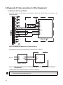
8.0 Appendix D: Interconnection to Other Equipment ........................................................44
8.1 Radionics 2071C and 2071AC .......................................................................................44
8.2 Silent Knight 5104 ..........................................................................................................45
8.3 CTM City Tie Module .....................................................................................................46
8.4 Keltron 3158 TTM ..........................................................................................................47
9.0 Warranty & Warning Information .....................................................................................48
9.1 Warning Please Read Carefully .....................................................................................48
9.2 Limited Warranty ............................................................................................................50
9.3 Warranty Procedure .......................................................................................................50
9.4 Disclaimer of Warranties ................................................................................................50
9.5 Out of Warranty Repairs ................................................................................................51
i
MR-2900 Installation Manual
List of Figures and Tables
Figure 1: Basic Network Communication Flow ....................................................................6
Figure 2: MR-2900 Exploded View ......................................................................................8
Figure 3: MR-2900 and MR-2944 in a Network ...................................................................10
Figure 4: Back Box Dimension and Knockout Reference ....................................................11
Figure 5: 120VAC Power Connection ..................................................................................12
Figure 6: 240VAC Power Connection ..................................................................................12
Figure 7: Conventional Style B (Class B) Wiring .................................................................12
Figure 8: Conventional Style A (Class A) Wiring .................................................................13
Figure 9: Smoke Detector Circuit Wiring, Style B (Class B) Wiring .....................................13
Figure 10: Smoke Detector Circuit Wiring, Style D (Class A) Wiring ...................................13
Figure 11: Normally Closed Wiring ......................................................................................14
Figure 12: Normally Open Wiring .........................................................................................14
Figure 13: Addressable Style 4(Class B) Wiring ..................................................................14
Figure 14: Addressable Style 6 (Class A) Wiring .................................................................15
Figure 15: MRI-M500M Wiring .............................................................................................16
Figure 16: MRI-M501 Wiring ................................................................................................16
Figure 17: MRI-M502M Wiring .............................................................................................17
Figure 18: MRI-M500S Wiring for Signalling Circuits............................................................17
Figure 19: MRI-M500R Wiring for Form C Relay Use .........................................................18
Figure 20: MRI-M500X Wiring .............................................................................................18
Figure 21: Style Y (Class B) Bell Circuit Wiring ...................................................................18
Figure 22: Style Z (Class A) Bell Circuit Wiring ...................................................................19
Figure 23: Relay ...................................................................................................................19
Figure 24 Auxiliary Power Connections ...............................................................................19
Figure 25: Ribbon Cable Installation ....................................................................................20
Figure 26: Standard Network Wiring ....................................................................................20
Figure 27: RS-232 Network Wiring ......................................................................................21
Figure 28: MR-2614, MR-2644, MR-2900-DACT and MR-2900-CITY Wiring .....................22
Figure 29: EVAX System Wiring ..........................................................................................22
Figure 30: MR-2900 and Radionics 2071C/2071AC Wiring ................................................44
Figure 31: MR-2900 and Radionics 2071C/2071AC Wiring with addressable module
substituted for alarm relay ..................................................................................44
Figure 32: MR-2900 and Silent Knight 5104 Dialer Wiring ..................................................45
Figure 33: MR-2900 and Silent Knight 5104 Dialer Wiring with addressable module
substituted for common alarm relay ....................................................................45
Figure 34: MR-2900 and Silent Knight 5104 Dialer Wiring with addressable module
substituted for common supervisory relay ..........................................................45
Figure 35: CTM City Tie Module Wiring ...............................................................................46
Figure 36: MR-2900 and Keltron 3158 TTM Wiring .............................................................47
Table 1: Input Circuit Module Compatibility .........................................................................4
Table 2: Maximum Wire Lengths for Conventional Input Circuits ........................................14
Table 3: Maximum Wiring Length for Addressable Circuits .................................................15
Table 4: Maximum Wire Lengths for Bell Circuits ................................................................19
Table 5: Maximum Capacitance for Network Baud Rates ...................................................21
iii
MR-2900 Installation Manual
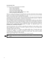
1.0 Technical Information
1.1 General
The MR-2900 Fire Alarm Control Unit provides capability for up to 24 Input Circuits, 8 Polarity Reversing
Bell Circuits, network capabilities (with use of an MR-2910 Network Board) and 4 General Purpose Form
"C" Relays as well as system operated relays for alarm, trouble and supervisory indication. If the MR-2900
is ordered with a printer, it is ordered under the panel number MR-2920.
The Control Unit can be networked to provide additional input circuits, visual zones, bell circuits and relays.
Up to 40 Units (Control and/or Annunciator) can be connected to form the network. The network is a Style
7 (Data Communications Link, Redundant (DCLR)) loop.
All programming is done through the LCD and keypad. Input circuit programming and special features,
day/night mode, etc., are done from an externally generated database, while system parameters are
programmed from the LCD and keypad. For programming information, refer to LT-2011 MR-2900
Programming Manual.
The basic MR-2900 Fire Alarm Control Unit consists of the:
•
•
•
•
•
•
Main Circuit Board (MR-2931)
Terminal Board (MR-2936)
Annunciator Strip (MR-2902)
Power Supply (MR-2905)
Door Assembly (MR-2972)
Back Box (MR-2971)
1.2 Main Circuit Board
The Main Circuit Board (MR-2931) provides system controls and visual indications, and contains the
system processor, programming port, printer port and non-volatile memory for system firmware. Software
is installed on the main board for critical functions such as programmable logic and timing functions and
non-critical functions, such as custom zone and devices messages. All jumpers on the board are for
diagnostic and test purposes. There are 6 LEDs in the middle of the right edge for diagnostic purposes.
The visual display consists of a series of LEDs for common system indication of power, alarm, supervisory,
and trouble. An LED clock display is provided to display real time. The flashing colon of the clock provides
visual indication of system processor operation. The clock also displays dashes if a major error/change
occurs. When this happens, the system requires a Hard reboot. A Hard reboot is done by pressing and
releasing the button inside the top of the inner door assembly.
The Circuit Board has an 80-character alphanumeric LCD. It provides descriptions for inputs, display of
archived events, first/last device in alarm, custom messages, etc. The keypad is used to scroll through the
display.
There are three connectors on the bottom of the Main Circuit Board, an audio output jack, a 9-pin service
terminal port and a 25-pin printer port. The ports are discussed below. The audio jack produces various
tones for use in walktesting of the system.
1
Communication Ports
The Control Unit has 6 communication ports available:
•
•
•
•
•
•
Port #1- network (Proprietary)
Port #2- network (Proprietary)
Port #3- general purpose (Proprietary)
Port #4- service terminal (RS232 - DB9)
Port #5- printer interface, Parallel (IBM/Centronics - DB25)
Port #6- serial printer interface (RS-232)
Ports 1 to 3 use the terminal strip on the Terminal Board for connection. Ports 4 and 5 use the connectors
mounted on the bottom of the Main Circuit Board. Port 6 uses a connector on the top of the Terminal
Board. It is for the optional factory installed MR-2920 strip printer.
The system network ports, Ports 1 and 2, allow for the networking of units. Up to 40 units (Control and/or
Annunciator) can be networked together. The network wiring is a Style 7 (DCLR) loop layout. An MR-2910
Series Network Board is required by each Control Unit to use these ports.
Port 3 is available for different uses depending upon the operating program loaded in the panel. Different
uses require different variants of the operating program. Typical uses are a central station connection or
remote LED annunciation of system status. The operation of this port is software defined and requires the
use of an MR-2109-x communications board. The MR-2109-3 Driver is for communication to MR-2614,
MR-2644, and the following dialers MR-2900-DACT and MRDL. The MR-2109-4 Driver is for
communication to the MV-2700 voice system.
The service terminal port, Port 4, permits the downloading and uploading of custom software, such as
device messages and I/O functions. It is intended for temporary connection to provide supplementary
information during servicing of the panel.
The parallel printer port, Port 5, connects to any standard parallel printer. The system prints every
occurrence as it happens. It is intended for temporary connection and can be used for system
commissioning and testing by producing a printed log of received events. This can then be checked
against a log of tests performed to confirm operation.
The serial printer interface, Port 6, is for the optional factory installed strip printer.
Note: If either of the printers or the service terminal printer screen is stalled, it causes the other printers
to stall.
2
MR-2900 Installation Manual
1.3 Front Panel
The system controls consist of 12 system switches and a 20
position alphanumeric keypad. The 12 system switches are
factory defined for operations such as alarm acknowledge,
signal silence and system reset. The 20-position keypad is used
for:
•
•
•
•
•
technical functions
system/detector maintenance
history recall
device/circuit disarming
manual operation of addressable output modules, relay
modules and bell circuits
1.4 Input Circuits
There are seven classes of conventional input circuits
supported by the Control Unit. Not all classes are supported by
all the Conventional Input Circuit Modules. See Table 1: Input
Circuit Module Compatibility on page 4 to determine which
circuits are supported by each module.
Conventional Input Circuits
•
•
•
•
•
•
"Class A" - This is a 4 wire supervised circuit
supporting normally open contact initiating devices.
Two-wire smoke detectors are not supported by this
type of circuit. A "Class A" circuit requires two of the
input circuits, one for the high loop and one for the low loop.
"Class B" - This is a 2 wire supervised circuit supporting only normally open contact initiating
devices and using a 470Ω End-of-Line Resistor, model EOL-471. Two-wire smoke detectors
cannot be used on this type of circuit.
Smoke Detector - This is a supervised circuit supporting two-wire smoke detectors only. Both
"Class B", using the 3.9KΩ Resistor (EOL-392), and "Class A" wiring is available depending upon
the Input Circuit Module used (see 1.5 Input Circuit Modules on page 4). Contact initiating devices
cannot be used with this type of circuit. A short is reported as a trouble, not as an Alarm.
Smoke Detector and Contact Device - This is a supervised circuit supporting two-wire smoke
detectors and normally open contact initiating devices. This circuit is wired the same as a Smoke
Detector circuit. Shorts on this type of circuit are reported as an Alarm, not as a trouble.
Normally Open - This is an unsupervised 2-wire circuit. Normally Open circuits are always
Supervisory circuits. This circuit is listed by UL for connection to other control equipment through
less than 20 feet of conduit.
Normally Closed - This is an unsupervised 2-wire circuit. This circuit shall not be used to monitor
fire alarm or supervisory initiating devices. This circuit is listed by UL for connection to other
control equipment through less than 20 feet of conduit.
Note: The Control Unit shows spurious alarms and troubles due to any mismatches between the
programmed circuit classes and the actual field wiring.
3
Addressable Input Circuits
There are two classes of addressable input circuits supported by the Control Unit:
•
•
"Class A" (Style 6) - This is a 4 wire circuit supporting addressable detectors and modules. It
requires two input circuits, one for signal out and one for signal return. Up to 99 detectors and up
to 99 modules can be connected to the circuit.
"Class B" (Style 4) - This is a 2 wire circuit supporting addressable detectors and modules. Up to
99 detectors and up to 99 modules can be connected to the circuit.
Note: Applicable codes and standards as well as good engineering practices must be considered with
regards to the number of addressable devices connected to one addressable circuit. Isolation
modules (MRI-500X) should be used whenever more than one fire zone is protected by one
addressable circuit.
1.5 Input Circuit Modules
There are five types of Input Circuit Modules. Table 1 circuit classes are supported by each conventional
module. All Input Circuit Modules control eight of the input circuits, one of circuits 1 to 8, 9 to 16 or 17 to 24.
Any of the Input Modules can be used to control circuits 9 to 16, and circuits 17 to 24. Addressable Input
Modules do not physically fit in the location for circuits 1 to 8.
Ground fault conditions occurring on the input circuits are indicated as to the circuit of origin.
Conventional Input Modules
•
Model MR-2928 - supports all seven classes of conventional circuits. Smoke detector circuits are
current limited to 80 mA while all other circuits are current limited to 10 mA.
Note: This board does not support 2-wire smoke detectors on a "Class A" circuit.
•
Model MR-2938 - supports only "Class A" 2-wire smoke detectors circuits. All circuits are current
limited to 80 mA.
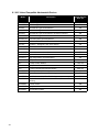
Table 1: Input Circuit Module Compatibility
MR-2928
9
Class A (Contact)
Class B (Contact)
MR-2938
9
Smoke Detector
“Class B” Only
“Class A” Only
Smoke Detector and Contact Device
“Class B” Only
“Class A” Only
Normally Open
9
Normally Closed
9
Dual End-of-Line
9
Addressable Input Modules
4
•
Model MR-2929 - supports both of 8 addressable Style 4 (Class B) circuits and 4 addressable
Style 6 (Class A) circuits
•
•
Model MR-2909 - supports 8 addressable Style 4 (Class B) circuits.
Model MR-2919 - supports 4 addressable Style 6 (Class A) circuits.
MR-2900 Installation Manual
1.6 Terminal Board
Field connections are terminated on the MR-2936 Terminal Board, which in addition to terminal blocks
contains a portion of the circuitry for output circuits and relays. The Terminal Board includes connections
for 24 input circuits, 8 supervised polarity reversing bell circuits, 4 general purpose Form "C" relays, 3
system Form "C" relays and 2 auxiliary power outputs. There is a five-pin terminal block on the bottom of
the Terminal Board for connection of the optional factory installed printer.
There are two versions of the Terminal Board. The MR-2926 Terminal Board has 8 Class B bells circuits.
The MR-2925 Terminal Board has 4 Class A bell circuits. The two versions are identical otherwise.The
MR-2936 supports 8 Class B bell circuits and 8 Class A bell circuits when a MR-2937 Class A Convertor
Board is installed.
The bell circuits are rated at 1.5 A @ 24 VDC. They are power-limited and protected with solid state fuses.
Note: Maximum system loading and stand-by battery power must be considered when determining
actual bell loading.
A 10 K end-of-line resistor, EOL-103, is required for supervision. Bell circuits are supervised for open, short
and ground fault conditions. The panel activates bell circuits in two modes: Evacuation, which activates the
bells continuously or with the temporal pattern as specified in ANSI S3.41 and ISO 8201 Audible
Emergency Evacuation Signal; Alert, which activates the bells in a repeated 12 s on and 3 s off.
The general purpose Form "C" relay operation is program defined. The relays have a power factor of .35
and are rated at 0.6A @ 30VAC / 2.0A @ 30VDC. The system defined Form "C" relays are for Alarm,
Supervisory and Trouble indication. These relays have a power factor of .35 and are rated 1.0A @ 24VDC
/ 0.5A @ 30VAC. The Trouble relay is normally energized so that loss of both AC power and battery power
is indicated. The N.O. and N.C. markings on the Trouble relay refer to this energized state.
The operation of the general purpose relays and bell circuits is totally program defined. It is possible to
program the activation of circuits to any zone, group of zones, device, group of devices and to further
inhibit the operation for a specifiable period of time. Any relays not programmed for use in either the
database or LCD menu are available for auxiliary power reset, i.e. the relay toggles for a programmable
time when the Reset key is pressed provided the programmed time is a value other than zero.
The auxiliary power outputs provide 24 VDC @ 135 mA each. They are supervised for shorts only. Any
load attached to the auxiliary power outputs have to be considered when calculating stand-by battery size.
1.7 Annunciator Strip
The Annunciator Board (MR-2902) contains 24 sets of zone indicating LEDs. Individual LEDs are provided
to display alarm, supervisory and trouble conditions by zone. The LED functions, from the left, are: Alarm
(red), Supervisory (amber or yellow) and Trouble (yellow). The LEDs flash on status change and go to
steady on acknowledge. The trouble LEDs turn on for both open circuit and ground fault with the specific
fault indicated on the LCD.
5
1.8 Power Supply
The Power Supply (MR-2905) is rated at 8A unregulated, providing the system with primary DC power. It is
complete with a battery charger rated at 2 A and battery supervision circuitry. The power supply and
battery are located within the control unit back box.
Battery supervision uses true dynamic supervision circuitry to simulate a load condition approximately
every 90 seconds to ensure that the battery is capable of handling the system load requirements on loss of
primary power.
If the battery voltage drops below 19V it is disconnected to protect against damage from a deep discharge.
A second compartment adjacent to the power supply compartment is provided for 120 VAC terminations.
Note: Never disconnect or reconnect the batteries while AC power is off.
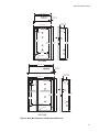
1.9 Enclosure
The enclosure for MR-2900 Control Unit consists of a back box complete with power supply, inner door
assembly complete with main control board, and outer door assembly. The back box and door assemblies
are fabricated from 1/16" steel. The outer door includes tempered glass window, hinge, and lock assembly.
The back box provides necessary "knock out" type openings for conduit entry.
The back box dimensions are 14 2" Wide x 27 2" High x 4" Deep. The outer door assembly is 16 7/8"
Wide x 29 2" High x 1 ¼" Deep. The details and dimensions of the enclosure and the MR-2920 Control
Unit with integrated printer are detailed below in section 1.11.
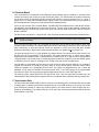
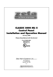
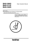
1.10 Networking
UNIT #2
UNIT #1
P2
P1
P2
UNIT #N
P1
P2
P1
Figure 1: Basic Network Communication Flow
The basic MR-2900 Control Unit can be networked to other Control Units and Annunciator Units to provide
additional input circuits, relays, bells and LEDs. Up to 40 units (Control and/or Annunciator) can be
networked together.
The network is a Class A/Style 7 DCLR loop layout (see diagram). Each unit on the network requires the
MR-2910 Network Board. Programming, servicing and testing are done at each individual unit. One
Control Unit is designated, using the downloaded database, the Master Control Unit for the network. The
Master Control Unit displays the Alarm List for the entire network if configured to do so. The Alarm List is
programmable such that events may be archived locally on each individual panel or the archived
collectively at the Master Panel. Please see the Programming Manual for further details.
There are four different MR-2910 boards available:
•
•
•
•
MR-2910
MR-2910-R1
MR-2910-R2
MR-2910-R12
Standard Version
Port 1 RS-232, Port 2 Standard
Port 1 Standard, Port 2 RS-232
RS-232 Version
Standard communications is for direct wire connections between units. RS-232 communications is for
connection to fiber optic modems only. Refer to the MR-D1010 Installation Instructions (LT-2048) for
information on connecting a fiber-optic network.
6
MR-2900 Installation Manual
For NFAPA Style 7 connection of the network, port 1 of node 1 is connected to port 2 of node 2. Port 1 of
node 2 is connected to port 2 of node 3. Port 1 of node 3 is connected to port 2 of node 4. Therefore, in
general, port 1 of node N is connected to port 2 of node N+1. The last node of the network is handled
differently.
For example, assume the system has a total of 30 nodes. In this case, the last node of the system is node
30. Port 1 of node 30 is connected to port 2 of node 1. Using this pattern the entire system would be
connected according to NFPA Style 7 for SLC connections.
Notes:
• Synchronized NAC devices can only function properly when driven by synchronization modules
provided by the NAC device manufacturer. Please consult compatibility list within this manual.
• Follow the instructions provided with the synch modules for proper interconnection of these
synch modules to the panel and to the NAC circuits.
• Synchronization across the network is not provided. Synchronization can only be done on a per
sync module basis. Therefore, only NAC circuits connected to sync modules on the same node
can be synchronized.
• Addressable NAC circuits cannot be synchronized.
1.11 Optional Integrated Printer
The MR-2900 Control Unit can be ordered integrated with the MR-2920 Printer. The MR-2920 Printer is a
20 column thermal printer. The Control Unit and Printer come in a larger cabinet
(MR-2973) with the Printer in a compartment adjacent to the Control Unit. A compartment for 12 Ah
batteries is located below the Control Unit and Printer.
The printer uses thermal paper. A Paper Advance button is on the right side of the Printer Compartment
Cover. If the paper runs out, the printer stops printing. To start printing after installing paper, hold the Paper
Advance button for a few seconds. Paper Out is reported to the Control Panel.
The Terminal Board, Power Supply Board and Toroid are in the main compartment of the back box in the
same locations as they are in the regular back box. The backbox dimensions for the BB-2920B enclosure
are 22 1/16” Wide x 27 ½” High x 5½” Deep. The outer door dimensions are 24 3/8” Wide x 29 1/2 High x
1 ¼” Deep.
7
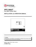
2.0 Installation
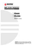
2.1 Unpacking the MR-2900
MR-2920
BB-2920B
BACKBOX
PRINTER
ASSEMBLY
TRANSFORMER
POWER
SUPPLY
BB-2900B
BACKBOX
DEAD
FRONT DOOR
USE #10 SCREWS
FOR MOUNTING
BACKBOX TO
WALL STUDS
PHONE DIALER
MODULE
ISOLATOR MODULE
ALL CIRCUITS EXCEPT AUX. POWER
ARE SUPERVISED
INNER DOOR
AND CPU
POWER SUPPLY
COMPARTMENT COVER
OUTER DOOR WITH
GLASS PANEL (MR-2920 SHOWN)
Figure 2: MR-2900 Exploded View
The basic MR-2900 package includes the following components:
Backbox
Outer door including:
•
•
•
Lock
Display window
Dead front door
Inner Door Assembly including:
•
•
•
•
•
Main PCB
Display PCB
Operating instruction insert
Hotkey label insert
Wiring label
Hardware backplate including:
•
•
•
Power Supply
Transformer
Terminal Board
Hardware pack including:
•
•
•
8
8 x NAC EOL resistors
Door keys (taped to outside of cabinet)
Installation manual and operating manual
MR-2900 Installation Manual
2.2 Mounting and Assembling the MR-2900
Note: All applicable codes and standards should be considered. Specific reference should be made to
NFPA 72, or ULC-S524 and CEC Part 1 Section 32.
Surface and Flush Mounting
The MR-2900 can be mounted in either flush or surface mount installations. Before installing the MR-2900
Panel the following should be considered.
1. Determine a suitable location for mounting the FACP. Keep in mind that surrounding walls, fixtures,
must not hinder access to internal components. etc.
2. Determine the size and location of conduit entrances. The Backbox provides various knockout
locations, however should it be necessary to cut additional conduit entrances the electronics must
be removed to avoid metal chip contamination. Reference the “Remove Electronics” paragraph on
the following page.
Note: Removing the inner door, outer door, and plate-mounted electronics is recommended in all MR2900 installations.
3. The enclosure must be mounted to provide a 135o (minimum) angle of rotation of the outer door to
insure easy removal or assembly.
4. Mark placement of mounting hardware, drill holes and install plugs (if necessary).
5. Secure the FACP to the wall using hardware suitable to the wall construction. Support backbox in
place while inserting hardware and ensure that the backbox is level and plumb before tightening.
Note: Please see the detailed diagram (Figure 2) for location of knockout and mounting holes.
Replacing the Outer Door
6. Unlock the Door with the key provided.
7. Detach the grounding strap (Qty: 2) from the backbox by removing the #6 flange nuts (Qty: 2) that
are attached to the studs on the backbox. Reattach the #6 flange nuts (Qty: 2) to the studs to prevent them from getting lost or discarded.
8. Open the Door to approximately 135o and lift up to remove the outer door from the backbox, store
door in a safe place.
Removing the MR-2900 Electronics
A. Removing the Dead Front
1. Remove the #6 flange nuts (Qty: 2) that lock down the dead front. Reattach the #6 flange nuts
(Qty: 2) to the studs to prevent them from getting lost or discarded.
2. Open the dead front.
3. Detach the grounding strap (Qty: 1) from the backbox by removing the #6 flange nut (Qty: 1) that is
attached to the stud on the backbox. Reattach the #6 flange nut (Qty: 1) to the stud to prevent it
from getting lost or discarded.
4. Open the dead front approximately 90° and lift up to remove the dead front, store in a safe place.
B. Removing the Inner Door
1. Detach the two ribbon cables.
2. Remove the four (4) flange nuts and remove the inner door.
3. Detach the ground straps (Qty: 2)
C. Removing the Back Plate Electronics
1. Detach the ribbon cable.
2. Remove the #8 flange nuts (Qty: 4) from the studs on the backbox holding onto the back plate.
Remove back Plate Electronic panel and store in a safe place. Reattach the #8 flange nuts to the
studs to prevent them from getting lost or discarded.
9
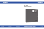
2.3 Internal Assembly
•
Attach AC wiring to the AC Terminal Block. Attach green ground wire to ground screw on
backplate.
Note: Do not apply power to the unit until all doors, cables and wiring are installed and inspected.
Note: This AC circuit must be a separately fused dedicated circuit. It is recommended that the breaker
be locked in the OFF position during installation.
•
•
•
•
Place the batteries in the bottom right of the back box or into the battery box. DO NOT ATTACH
BATTERIES UNTIL AFTER THE AC POWER HAS BEEN TURNED ON.
Attach conduit to the back box as required using knockouts provided. Attach field wiring to the
system. The section below describes how each type of circuit is to be wired. Attach conduit to the
back box as required using knockouts provided. It is recommended that input circuit wiring be
physically separated from output circuit wiring.
Have the Unit inspected before applying power. Correct and re-inspect any problems found.
Turn on the AC power to Unit. If no problems occur other than Low Battery, attach the batteries to
the wires provided, the black wire to the black (negative) terminal and the red wire to the red
(positive) terminal. If the batteries need charging, the Low Battery condition remains until they are
charged.
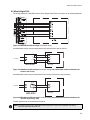
Note: For Canadian installations in a network environment, a LED annunciator is required mounted next
to the Master Panel.
Use MR-2944-ANN chassis mounted in one of the following boxes as required:
• MR-2944-BBS annunciator enclosure for four strips
• MR-2944-BBL annunciator enclosure for eight strips
Refer to LT-2020 MR-2944 Installation
Manual
for
detailed
installation
information.
Main MR-2900
MR-2900
MR-2900
MR-2944
MR-2900
Figure 3: MR-2900 and MR-2944 in a Network
Note: The MR-2944 must be physically located next to the Main MR-2900 Panel.
10
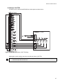
MR-2900 Installation Manual
14-1/2" (368 mm)
7/8" (23 mm)
lip each side
3/4" (19 mm) lip
top and bottom
16-7/8" (429 mm)
4"
(102 mm)
3" (76 mm)
1-1/4"
(32 mm)
21-3/4"
(552 mm)
26-1/2"
(673 mm)
27-1/2"
(699 mm)
29-1/2"
(750 mm)
8-1/2"
(216 mm)
Battery shelf
BB-2900B
22-1/16" (560 mm)
7/8" (23 mm)
lip each side
3/4" (19 mm) lip
top and bottom
24-3/8" (620 mm)
5-1/2"
(140 mm)
3" (76 mm)
Printer Section
1-1/4"
(32 mm)
Control Panel Section
26-1/2"
(673 mm)
29"
(740 mm)
27-1/2"
(699 mm)
21-3/4"
(552 mm)
16" (406 mm)
Battery shelf
BB-2920B
Figure 4: Back Box Dimension and Knockout Reference
11
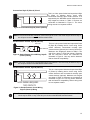
2.4 Wiring
Power Connections
The Main Control Unit requires an AC power supply. See Figures 5 and 6 below.
The batteries forming the Battery Pack are wired in series. The Battery Pack attaches to the two wires
coming from the Power Supply Board, the black wire to the black (negative) terminal and the red wire to
the red (positive) terminal. The internal batteries are not used when an external battery box is used. The
wires for connecting the power supply board to the batteries are supplied with the panel if a battery box is
ordered at the same time.
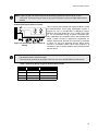
Figure 5: 120VAC Power Connection
Figure 6: 240VAC Power Connection
Warning: Never connect or disconnect the batteries while the AC power is off.
Conventional Style B (Class B) Circuit
EOL-471
Figure 7: Conventional Style B (Class B) Wiring
This is a 2-wire power-limited and supervised Style
B (Class B) initiating device circuit using
conventional normally open contact devices and an
end-of-line resistor, supported by the MR-2928
smoke and contact module. Maximum wire lengths
are shown in Table 2. The end-of-line resistor is a
470Ω resistor EOL-471. Devices and the end-ofline resistor are connected as illustrated in Figure 7.
Note: 2-wire smoke detectors cannot be used on this type of circuit. This circuit may be wired on any of
the 24 input circuits on the MR-2900 terminal boards.
12
MR-2900 Installation Manual
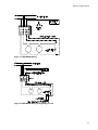
Conventional Style D (Class A) Circuit
This is a 4-wire power-limited and supervised Style
D (Class A) initiating device circuit using
conventional normally open contact devices. It is
supported by the MR-2928 module. Maximum wire
loop lengths are shown in Table 2. Devices are
connected as illustrated in Figure 8. The return
wiring must be in a separate conduit.
+
Figure 8: Conventional Style A (Class A) Wiring
Note: 2-wire smoke detectors cannot be used on this type of circuit. This circuit may be wired on any of
the 24 input circuits on the MR-2900 terminal boards.
Smoke Detector Circuits, Style B (Class B)
This is a 2-wire power-limited and supervised Class
B (Style B) initiating device circuit using 2-wire
smoke detectors, conventional normally open
EOL DEVICE
contact devices (optional) and a end-of-line device.
Maximum wire lengths are shown in Table 2. The
end-of-line device is EOL-392 resistor. Detectors
Figure 9: Smoke Detector Circuit Wiring, Style B
and the end-of-line device are connected as
(Class B) Wiring
illustrated in Figure 9. Use only smoke detectors
that are listed for compatibility.
EOL-392
Note: This circuit is supported by the MR-2928 Input Circuit Module. This circuit may be wired on any of
the 24 input circuits on the MR-2900 terminal boards.
Smoke Detector Circuits, Style D (Class A)
+
+
+
NOTE: WIRING REQUIRES
TWO CIRCUITS
This is a 4-wire power-limited and supervised Style
D (Class A) initiating device circuit using 2-wire
smoke detectors and conventional normally open
contact devices (optional). Maximum wire lengths
are shown in Table 2. Detectors are connected as
illustrated in Figure 10. Use only smoke detectors
that are listed for compatibility. Return wiring must
be in a separate conduit.
Figure 10: Smoke Detector Circuit Wiring,
Style D (Class A) Wiring
Note: This circuit is supported only by the MR-2938 Conventional "Class A" Input Circuit Module. This
circuit may be wired on any of the 24 input circuits on the MR-2900 terminal boards.
13
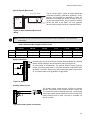
Normally Closed Circuit
Figure 11: Normally Closed Wiring
This is a 2-wire non-supervisory circuit and is
supported by the MR-2928 module. This circuit is
listed by UL for connection to other control
equipment through less than 20 feet of conduit.
Devices are connected as illustrated in Figure 11.
Maximum wire lengths are shown in Table 2.
Notes:
• This circuit shall not be used to monitor fire alarm or supervisory initiating devices. This circuit
may be wired on any of the 24 input circuits on the MR-2900 terminal boards.
• All distances refer to total wire length.
Normally Open Circuit
This is a 2-wire supervisory circuit. It is supported by
the MR-2928 module. This circuit is listed by UL for
connection to other control equipment through less
than 20 feet of conduit. Devices are connected as
illustrated in Figure 12. Maximum wire lengths are
shown in Table 2.
Figure 12: Normally Open Wiring
Note: No fire alarm initiating devices can be connected to this class of circuit. This circuit may be wired
on any of the 24 input circuits on the MR-2900 terminal boards.
Table 2: Maximum Wire Lengths for Conventional Input Circuits
AWG
Length
14
7 620m (25 000 ft)
16
4 846m (15 900 ft)
18
3048m (10 000 ft)
22
1524m (5 000 ft)
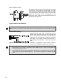
Addressable Style 4 (Class B) Circuit
Figure 13: Addressable Style 4(Class B)
Wiring
14
This is a 2-wire power-limited and supervised Style 4
(Class B) communications circuit using addressable
devices. It requires the use of the MR-2929 or MR-2909
module. Wire capacitance and resistance affects the
allowable wire length. The recommended wiring is
twisted
unshielded
pair.
Consult
Secutron's
Applications Department for specific requirements.
Maximum wire lengths are up to 10,000 ft (see Table
3). Devices are connected as illustrated in Figure 13.
Use only approved devices.
MR-2900 Installation Manual
Note: T-taps may NOT be allowed by the authority having jurisdiction. Refer to NFPA 72 and
ULC-S524. This circuit may be wired on any input circuit from 9 to 24 on the MR-2900 terminal
boards.
Addressable Style 6 (Class A) Circuit
Figure 14: Addressable Style 6 (Class A)
Wiring
This is a 4-wire power-limited and supervised Style 6 (Class
A) communications circuit using addressable devices. It
requires the use of the MR-2929 or MR-2919 module.
Maximum wire loop lengths are up to 10 000 ft (see Table
3). The recommended wiring is twisted unshielded pair.
Wire capacitance and resistance affects the allowable wire
length. Consult Secutron's Applications Department for
specific requirements. Devices are connected as illustrated
in Figure 14. Use only approved devices. Return wiring
must be in a separate conduit. When using isolators, it is
necessary to put an isolator between panel terminal blocks
and the device.
Notes:
• All distances refer to total wire length.
• This circuit may be wired on any input circuit from 9 to 24 on the MR-2900 terminal boards.
Table 3: Maximum Wiring Length for Addressable Circuits
Gauge
Belden No.
Distance
12
9582
3 048m (10 000 ft)
14
9580
2 438m (8 000 ft)
16
9572
1 402m (4 600 ft)
18
9571
975m (3 200 ft)
15
Addressable Modules
The addressable module extended circuits are wired as shown on the next page in Figures 15 - 20.
Figure 15: MRI-M500M Wiring
Figure 16: MRI-M501 Wiring
16
MR-2900 Installation Manual
Figure 17: MRI-M502M Wiring
Figure 18: MRI-M500S Wiring for Signalling Circuits
17
NC 8
NO 7
COMMON 9
5 NC
4 NO
6 COMMON
Figure 19: MRI-M500R Wiring for Form C Relay Use
Figure 20: MRI-M500X Wiring
Style Y (Class B) Bell Circuit
Regulated 24 FWR
EOL
10 k
This is a 2-wire Style Y (Class B) power-limited and
supervised signalling (notification appliance) circuit.
Devices and the 10 k end-of-line resister are connected
as illustrated in Figure 21. Maximum wire lengths are
shown in Table 4. Use only approved devices.
EOL-103
Figure 21: Style Y (Class B) Bell Circuit
Wiring
Note: The inrush current of some devices may cause the current to exceed the 1.5A current limit
momentarily.
18
MR-2900 Installation Manual
Style Z (Class A) Bell Circuit
Regulated 24 FWR
MR-2937
“Class A”
Converter
This is a 4-wire Style Z (Class A) power-limited and
supervised signalling (notification appliance) circuit.
Devices are connected as illustrated in Figure 22.
Maximum wire lengths are shown in Table 4. This is
for the total length of wire, from the panel to furthest
device and back to the panel. Use only approved
devices. Return wiring must be in a separate conduit.
Figure 22: Style Z (Class A) Bell Circuit
Wiring
Note: The inrush current of some devices may cause the current to exceed the 1.5A current limit
momentarily.
Table 4: Maximum Wire Lengths for Bell Circuits
250 mA
500 mA
750 mA
1.0 A
1.25 A
1.50 A
12 AWG
1220m (4000 ft)
610m (2000 ft)
407m (1300 ft)
305m (1000 ft)
244m (800ft)
203m (667ft)
14 AWG
732m (2400 ft)
366m (1200 ft)
244m (800 ft)
183m (600 ft)
146m (480ft)
122m (400ft)
16 AWG
457m (1500 ft)
229m (750 ft)
152m (500 ft)
114m (375 ft)
91m (300ft)
76m (250ft)
Relay Connections
Unused relays are left unconnected. General Purpose Relays and System
Relays operate identically and are wired the same (see Figure 23).
All relay wiring is unsupervised. The general purpose relays (Function
Relays 1-4) have a power factor of .35, power-limited at .6A @ 30VAC/2.0A
@ 30VDC. The Alarm, Supervisory, and Trouble relays have a power factor
of .35, power-limited at .5A @ 30VAC/1.0A @ 24VDC.
Figure 23: Relay
Auxiliary Power Circuits
The auxiliary power circuits provide 24 VDC for external
devices. The polarity of the circuits is shown in Figure 24.
The Control Unit does not interrupt this circuit. For the wiring
to be power-limited and supervised an end-of-line relay (Part
number PAM-3) must be used. The relay is a 24VDC coil
with 3A contacts.
Figure 24 Auxiliary Power Connections
19
Inner Door Ribbon Cables
Two ribbon cables connect the Terminal Board to the Main
Circuit Board. These cables are on the hinged side of the
Inner Door and are long enough that the Inner Door can be
fully opened without removing the cables. Ensure that the
cables are not twisted and is seated properly in the
connectors. These cables must be attached before the unit
is powered (see Figure 25).
Figure 25: Ribbon Cable Installation
Note: Inserting or removing the ribbon cables while the unit is powered can result in damage to the unit.
Standard Network Wiring
Standard Network wiring uses a twisted pair of wires
between each panel (see Figure 26). The COM1 of each
Unit is connected to the COM2 of the next Unit. MR-2944
Annunciator Unit are connected the same as the Control
Unit. Wiring is not polarity sensitive. Network wiring is
power-limited. Only COMLINK 1 is supervised for ground
faults.
Figure 26: Standard Network Wiring
COMLINK 2 is supervised for ground faults through its
connection to COMLINK1 of previous attached panel.
Note:
• Ensure that only one COM2 is connected to each COM1. If two or more are connected, the
network segment does not work.
• The following table shows the maximum wiring capacitance for the various baud rates supported
by the Network using the standard MR-2910. The maximum allowable line resistance is 680
ohms.
20
MR-2900 Installation Manual
Table 5: Maximum Capacitance for Network Baud Rates
Baud Rate
Maximum Capacitance
Maximum Network Nodes
9600
100 nF
254
4800
220 nF
254
2400
470 nF
254
1200
680 nF
200
RS-232 Network Wiring
RS-232 Network wiring uses three (3) wires between each panel (see
Figure 27). The COM1 of each Unit is connected to the COM2 of the next
Unit. MR-2944 Annunciator Units are connected the same as the Control
Unit. Wiring is polarity sensitive.
Figure 27: RS-232 Network
Wiring
Notes:
• Ensure that only one COM 2 is connected to each COM 1. If two or more are connected, the
network segment does not work.
• The wire length limit for RS-232 is 20 feet (6m) in conduit, in the same room. For systems using
modems, this is the maximum distance between the panel and the modem.
MR-D1010R Wiring
Refer to LT-2048 MR-D1010R Fiber Optic Module Installation Instructions.
21
Annunciator, UDACT and Reverse Polarity Wiring
The MR-2614 and MR-2644 Annunciators, the MR2900-CITY Reverse Polarity module and the MR2900-DACT Dialer are connected to COMLINK 3 of
the panel by 4 wires; 2 for power and 2 for
communications. The communications wiring is
polarity sensitive. An example of the wiring is shown
in Figure 28. Up to eight of each type of annunciator
and either one dialer or one reverse polarity module
can be connected to the MR-2900. If more than one
MR-2614 is used, the 3.9kΩ resistor across the MR2614 terminals should be removed from all but the
last MR-2614. The MR-2900 panel requires that the
MR-2109-3 communications board be installed. The
maximum length of communications wiring is 900m
(3000 ft) using 22 AWG. The maximum length of
power wiring is 300m (1000 ft) using 18 AWG.
Figure 28: MR-2614, MR-2644, MR-2900DACT and MR-2900-CITY Wiring
Evax System Wiring
MR2900 BACKPLATE
MV 2700 M
CONDUIT
20’ MAX
MR2925 OR MR2926
TERMINAL BOARD
TX
RX
TS3
GND
TX
COMLINK 3
RX
TB9
GND
Figure 29: EVAX System Wiring
**The MR-2900 panel requires the use of the MR-2109-4 board.
Notes:
• For all EVAX installations, the maximum wiring distance from the FACP to the HMX panel is 20
feet in conduit. The two panels must be in the same room.
• MV-2700M and MV-2700D are not ULC listed.
• MV-2700M must be connected to an MV-2700D. The MV-2700M (M = Master) generates the
audio signals. The MV-2700D (D = Distributed) distributes the audio signal via NACs.
• For information on connecting an MV-2700M to an MV-2700D, refer to those modules installation
instructions.
• Devices connected to COMLINK 3 are to be installed close nippled.
22
MR-2900 Installation Manual
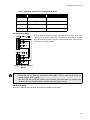
3.0 Technical Specifications
Electrical Ratings
AC Line Voltage
AC Brownout@120V
@240V
Battery
Current Consumption
120 V, 60 Hz / 240 V, 50 Hz
2A / 1A
90 VAC NSC / 93 VAC Alarm
180 VAC NSC / 186 VAC Alarm
24 Volt Sealed lead acid, up to 52 AHr
500 mA in standby
8 Amps Max. in alarm
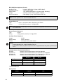
Compliance
System Model: MR-2900 Series Fire Alarm Control Panel
System Type: Local, auxiliary (using MR-2900-CITY), remote protected premise station (using MR-2900CITY or MR-2900-DACT), central station protected premises (using MR-2900-DACT).
Type of Service: A, M, WF, SS (with MR-2900-CITY or MR-2900-DACT)
Type of Signalling: Non-coded
Applicable Standards: NFPA 70 and 72, UL-864 Rev.9, ULC S-524, ULC S-527-99 Input (Initiating
Device) Circuits (24)
Conventional
Addressable
Voltage
24 VDC
24 VDC
Ripple Voltage
2 V p-p
N.A.
Contact Devices
5 mA
N.A.
Smoke Detectors
10 mA
N.A.
Contact Devices
10 mA
N.A.
Smoke Detectors
80 mA
N.A.
Max. No. of Devices
25 (Smoke Detectors)
99 Detectors / 99 Modules
Compatible Devices
MR Series
MR Series
Supervisory Current
Alarm Current
Note: Consult 6.0 Appendix B: ULC Listed Compatible Smoke Detectors on page 28 or 7.0 Appendix C:
UL Listed Compatible Devices on page 31
End of Line Device
Contact Circuit
470Ω Resistor (EOL-471)
N.A.
Smoke Detectors
EOL-392
N.A.
Total Line Resistance
200Ω
40Ω
Total Line Capacitance
100 uF
0.5 uF
Total Line Length
See Table 2
See Table 3
T-Tapping
No
Class B (Style 4) Only
23
Bell (Notification Appliance) Circuits
Number & Type
Supervisory Current
Alarm Current
Voltage
End of Line Device
8 Class B, NFPA Style Y/ Class A, NFPA Style Z
1.0 mA, power limited
1.5 A, power limited (NAC/1.0 A, power limited, Releasing)
24 VDC, nominal, full wave rectified, unfiltered
Class B (Style Y) only: 10 KΩ Resistor, EOL-103
Note: Consult Appendix C UL Listed Compatible Devices
System Relays (3)
Type
Rating
Form C, one each for Alarm, Supervisory and Trouble
0.5 A @ 30VAC (resistive) / 1.0A @ 24VDC
Note: These relays are not listed by UL for use for connection to equipment outside the same room as
the Control Panel.
General Purpose Relays (4)
Type
Rating
Form C
0.6A @ 30VAC (resistive) / 2.0A @ 30VDC
Auxiliary Power Outputs (2)
Voltage
Ripple Voltage
Current
24 VDC
2 Vrms, maximum
135 mA per circuit, power limited
Notes:
• Consult Appendix C UL Listed Compatible Devices
• If load exceed 135mA, any NAC output circuit can be programmed as Aux power to provide up to
1.5 A.
MR-2910 Network Communication Boards
MR-2910
MR-2910-R1
MR-2910-R2
MR-2910-R12
Network Communication Module, Both Ports Standard
Network Communication Module, Port 1 RS-232, Port 2 Standard
Network Communication Module, Port 1 Standard, Port 2 RS-232
Network Communication Module, Both Ports RS-232
Standard
Wire Type
Twisted Pair
RS-232
Twisted Pair
Gauge
18-22 AWG
18-22 AWG
Distance
*10 km (apr. 6 miles)
Under 6m (20 ft)
Application
Direct Wire
Fiber Optic Modem
*Using 22 AWG wire.
Battery Boxes
Model
24
Capacity
Size
MR-2978B
24-52 Ah
21" x 9" x 7" white
MR-2978R
24-52 Ah
21" x 9" x 7" red
MR-2900 Installation Manual
4.0 Parts List
Model
Description
Basic Control Unit
MR-2900
Basic Control Unit (with or without MR-2920 strip printer)
Optional Modules
MR-2928
Conventional Input Circuit Module, 8 Circuit, Software Selectable for 10 or
80 mA, smoke and contact circuits
MR-2938
Conventional Input Circuit Module, 4 Circuit, "Class A", 80 mA, smoke and
contact circuits
MR-2929
Addressable Input Circuit Module, 8 Circuit, "Class B" / 4 Circuit, "Class A"
MR-2909
Addressable Input Circuit Module, 8 Circuit, "Class B"
MR-2919
Addressable Input Circuit Module, 4 Circuit, "Class A"
MR-2910
Network Communication Module, Both Ports Standard
MR-2910-R1
Network Communication Module, Port 1 RS-232, Port 2 Standard
MR-2910-R2
Network Communication Module, Port 1 Standard, Port 2 RS-232
MR-2910-R12
Network Communication Module, Both Ports RS-232
MR-2109-3
Port 3 Communications Board for connection to MR-2614, MR-2644, MR2900-DACT and MR-2900-CITY
MR-D1010R1
Fiber Optic Module, One Modem
MR-D1010R2
Fiber Optic Module, Two Modem
Annunciators
MR-2944
Annunciator Driver
MR-2944LCD
Annunciator Driver c/w 80 Character LCD
MR-2614
LED Annunciator
MR-2614EH
Enhanced LED Annunciator
MR-2644
LCD Annunciator
MR-2915
LED Driver for Annunciators
MR-2902
Annunciator Strip, 3 x 24 LEDs
MR-2622
Annunciator Strip, 3 x 8 LEDs
Accessories
MHI
Modul-R Human Interface database editor
EOL-471
470Ω End-of-Line Resistor for conventional contact circuits
EOL-103
10kΩ End-of-Line Resistor for bell circuits
ELRX-300(W/R)
Plate for End-of-Line Resistor
EOL-392
End-of-Line Device for conventional smoke circuits
Replacement Modules - Consult the factory
Hardware
MR-2978(B/R)
Battery Box for 17 and 24 AHr batteries c/w cables, 21" W x 9" H x 7" D
BA-104
4.0 AHr Battery
BA-1065
7.0 AHr Battery
BA-110
10 AHr Battery
BA-117
17 AHr Battery
BA-124
24 AHr Battery
25
5.0 Appendix A: Power Supply and Battery Calculations
IMPORTANT NOTICE
The main AC branch circuit connection for Fire Alarm Control Panel must provide a dedicated continuous power without provision of any disconnect
devices. Use #12 AWG wire with 600-volt insulation and proper over-current circuit protection that complies with the local codes. Refer to 3.0 Technical
Specifications on page 23 for specifications.
POWER REQUIREMENTS (ALL CURRENTS ARE IN AMPERES)
Model Number
MR-2900
Description
Fire Alarm Control Unit (includes
MR-2931, MR-2905, MR-2902
MR-2900
Unique LED’s
Qty
Total
Standby
Standby
Total
Alarm
Alarm
X
0.092
=
0.107
=
X
0.005
=
n/a
=
MR-2910
Network Communication Module
X
0.005
=
0.005
=
MR-2938
Conventional Input Circuit Module
X
0.018
=
0.101
=
MR-2929
Addressable Input Circuit Module
X
0.050
=
0.050
=
MR-2909
Addressable Input Circuit Module
X
0.001
=
0.001
=
MR-2928
Conventional Input Circuit Module
X
0.014
=
0.094
=
MR-2919
Addressable Input Circuit Module
X
0.005
=
0.005
=
MR-2614
LED Annunciator
X
0.020
=
0.155
=
MR-2622
Annunciator Strip
X
0.005
=
0.125
=
MR-2644
LCD Annunciator
X
0.030
=
0.070
0.315
=
MR-2900-CITY
City Card
X
0.020
=
(reverse polarity mode)
0.035
=
(in alarm (+ load - 65mA for
3 circuits)
MR-2900-DACT
Digital Communication Module
X
0.040
=
0.060
=
MR-2109-3
Digiquad Module
X
0.008
=
0.0008
=
MR-2944
Annunciator
X
0.075
=
0.075
=
MR-2915
LED Driver Card
X
0.001
=
0.010
=
MR-2920
Strip Printer
X
0.125
=
0.800 when printing
=
MR-D1010-R1
Fibre Optic Modem
X
0.075
=
=
MR-D1010-R2
Fibre Optic Modem
X
0.150
=
=
MR-2690
Isolation Module
X
0.010
=
=
Two-Wire Smoke Detectors
X
š
=
=
Four-Wire Smoke Detectors
X
š
=
=
Signal Load (bells, horns, strobes, and etc.)
X
š
=
=
=
=
Auxiliary Power Supply for Annunciators, etc.
Total currents (Add above currents)
STANDBY
(A)
ALARM
(B)
Ò See 6.0 Appendix B: ULC Listed Compatible Smoke Detectors on page 28 and 7.0 Appendix C: UL Listed Compatible Devices on page 31 for other compatible
devices.
Total Current Requirement: ALARM (B)______ Amps. (Value obtained from column B)
Battery Capacity Requirement:
Battery (AH) = ([STANDBY (A) ______ ] x [(24,60 or 90 Hours) ___ ]) +
([ALARM (B) ______ ] x [Alarm in Hr.] _____) = (C) ______AH
Battery Selection: Multiply (C) by 1.20 to derate battery.
26
MR-2900 Installation Manual
5.1 General
Batteries are designed and manufactured for a specific use. "Standby" is one of these uses. They are rated
according to their ability to deliver a steady current for 20 hours ("20 Hour Rating"). A 10 Ah battery is
unable to deliver 10 A for 1 hour, however it does deliver 2 A (500 mA) for 20 hours. A car battery is
designed to deliver "cranking" power for a short time, (a few hundred Amps for a few minutes).
Unfortunately, fire alarm control panels need both of these characteristics, that is, driving a heavy bell load
for a relatively short time, at the end of a 24 hour standby current drain. This protection necessitates
certain over sizing.
Regardless of the standby calculation and tables, the battery must be at least 150% of the bell load. e.g. A
4 A total bell load necessitates at least 6 A hour battery (in terms of 20 hour rating).
Note: The MR-2900 Control Panel is capable of driving a bell load of 8 A maximum. This restriction
must be considered when laying out a bell system..
The standard battery options available for the MR-2900 Control Unit are:
a) 4 AHr internal
b) 7 AHr internal
c) 10 AHr internal
d) 17 AHr external in a separate battery cabinet
e) 24 AHr external in a separate battery cabinet
f) 52 AHr external in a separate battery cabinet
27
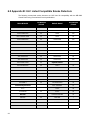
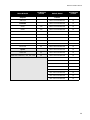
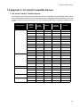
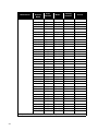
6.0 Appendix B: ULC Listed Compatible Smoke Detectors
The following conventional smoke detectors are ULC listed for compatibility with the MR-2900
Control Panel using Conventional Circuit Input Modules
Make & Model
# of Devices
/Circuit
Hochiki
# of Devices
/Circuit
Mirtone
DCD-135/NS6-220
30
73471
30
DCD-135/NS4-220
30
73494
100
DCD-135/HSC-220R
30
73575
60
DCD-190/NS6-220
30
73495/73486
100
DCD-190/NS4-220
30
73495/73487
100
DCD-190/HSC-220R
30
73595/73486
60
SIJ-24/NS6-220
30
73595/73497
60
SIJ-24/NS4-220
30
73594/73400
60
SIJ-24/HSC-220R
30
73405/73400
100
SLR-24/NS6-220
30
73594/73401
60
SLR-24/NS4-220
30
73405/73401
100
SLR-24/HSC-220R
30
System Sensor
SLR-24H/NS6-220
30
1400-A
30
SLR-24H/NS4-220
30
2400-A
25
SLR-24H/HSC-220R
30
1451-A/B401B
25
SLR-835/NS6-220
30
1451-A/B406B
25
SLR-835/NS4-220
30
2451-A/B401B
25
SLR-835/HSC-220R
30
2451-A/B406B
25
SLR-835B-2
30
1451DH/DH400A
30
Cerebrus Pyrotronics
2451-A/DH400A
25
D1-2
1151A
30
2151A
30
C2W-BA/C2WT-BA
30
D1-3/DB-3S
30
Mircom
28
Make & Model
MIR-525
30
C2WTR-B
1
MIR-525T
30
C2WTA-BA
1
MIR-1400A
30
NAPCO
MIR-2400A
25
FW-2
30
MR-2900 Installation Manual
Make & Model
# of Devices
/Circuit
Make & Model
# of Devices
/Circuit
Simplex
Fenwal
2098-9110
PSD-7131/70-201000-001
42
Edwards
PSD-7131/70-201000-002
42
6249C
100
PSD-7131/70-201000-003
42
6250C
100
PSD-7131/70-201000-005
42
6264C
100
PSD-7130/70-201000-001
42
6266C
60
PSD-7130/70-201000-002
42
6269C
60
PSD-7130/70-201000-003
42
6270C
60
PSD-7130/70-201000-005
42
6269C-003
60
PSD-7128/70-201000-001
42
6270C-003
60
PSD-7126/70-201000-002
42
PSD-7126/70-201000-003
42
Apollo
55000-325
30
PSD-7126/70-201000-005
42
55000-325 / 45681-251, -255, -256, -258
30
PSD-7129/70-201000-000
42
PSD-7125/70-201000-001
42
PSD-7126/70-201000-002
42
PSD-7125/70-201000-003
42
PSD-7125/70-201000-005
42
CPD-7021/70-201000-001
42
CPD-7021/70-201000-002
42
CPD-7021/70-201000-003
42
CPD-7021/70-201000-005
42
29
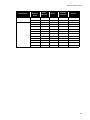
6.1 ULC Listed Compatible Addressable Devices
Model
30
Description
Typical Current
Draw µA
MRI-1251
Ionization type smoke detector
300
MRI-1251B
Ionization type smoke detector
300
MRI-2251
Photoelectric type smoke detector
300
MRI-2251B
Photoelectric type smoke detector
360
MRI-2251T
Photoelectric type smoke detector w/ thermal element
300
MRI-2251TB
Photoelectric type smoke detector w/ thermal element
360
MRI-2251TM
Acclimate Photo-Thermal Detector
300
MRI-2251TMB Acclimate Photo-Thermal Detector
360
MRI-7251
Pinnacle™ Intelligent Laser Some Sensor
330
MRI-5251P
Thermal detector
200
MRI-5251B
Thermal detector
300
MRI-5251RP
Thermal detector w/ rate of rise
200
MRI-5251RB
Thermal detector w/ rate of rise
300
MRI-5251H
High Temperature Thermal detector
300
IM-10
10 Input Monitor Module
3.50 mA
CR-6
6 Relay Control Module
1.45 mA
SC-6
6 Supervised Control Module
2.25 mA
CZ-6
6 Zone Conventional Interface Module
2.00 mA
MRI-M500DM Dual Input Monitor Module
300
MRI-M500M
Monitor module, Classes A/B initiating
300
MRI-M501M
Mini Monitor module, Class B initiating
300
MRI-M502M
Monitor Module for 2- wire smoke detectors Classes A/B
initiating
200
MRI-M500S
Control module
300
MRI-M500R
Relay Module
300
MRI-M500X
Fault isolator module
450
MR-2900 Installation Manual
7.0 Appendix C: UL Listed Compatible Devices
7.1 UL Listed “Class B” Smoke Detectors
The following Listed 2-wire smoke detectors and bases are compatible with the MR-2900 Control Panel
using the MR-2928 Conventional Input Circuit Modules (with compatibility identifier MR-2928). Up to 5 μA
of smoke detector normal standby load may be connected to MR-2928 conventional initiating device
circuit.
Manufacturer
System Sensor
Apollo
Smoke
Detector
Model
Base
Identifier
Standby
Identifier
Model
Current
1400
A
N/A
N/A
100 μA
1451
A
B401
A
120 μA
1451
A
B401B
A
120 μA
2300T
A
N/A
N/A
120 μA
2300TB
A
N/A
N/A
120 μA
2400
A
N/A
N/A
120 μA
2400TH
A
N/A
N/A
120 μA
2451
A
B401
A
120 μA
2451
A
B401B
A
120 μA
2451
A
DH400
A
120 μA
2451TH
A
B401
A
120 μA
2451TH
A
B401B
A
120 μA
55000-250
55000-250
45681-200
45681-200
59 μA
55000-250
55000-250
45681-230
45681-230
80 μA
55000-250
55000-250
45681-231
45681-231
80 μA
55000-350
55000-350
45681-200
45681-200
110 μA
55000-350
55000-350
45681-230
45681-230
130 μA
55000-350
55000-350
45681-231
45681-231
130 μA
DS200
A
MB200-2W
A
80 μA
DS200HD
A
MB200-2W
A
80 μA
6250B
001
6251B
001
30 μA
6270B
001
6251B
001
50 μΑ
Cerebrus
DI-3C
Pyrotronics
DI-4
DI-4B
PEC-3
Detection Systems
Edwards
31
Manufacturer
Fenwal
Smoke
Detector
Model
Base
Identifier
Model
Standby
Identifier
CPD-7023
I3FE1
CPD-001
FE01A
80 μA
CPD-7023
I3FE1
CPD-002
FE02A
80 μA
CPD-7023
I3FE1
CPD-003
FE03A
80 μA
CPD-7023
I3FE1
CPD-005
FE05A
80 μA
CPD-7051
I3FE1
2-Wire
FE51A
60 μA
CPD-7051
I3FE1
2WRLT
FE52A
60 μA
CPD-7051
I3FE1
2WRB
FE53A
60 μA
CPD-7051
I3FE1
CPD-001*
FE01A
60 μA
CPD-7051
I3FE1
CPD-002*
FE02A
60 μA
CPD-7051
I3FE1
CPD-003*
FE03A
60 μA
CPD-7051
I3FE1
CPD-005*
FE05A
60 μA
PSD-7134
P14FE1
CPD-001
FE01A
120 μA
PSD-7134
P14FE1
CPD-002
FE02A
120 μA
PSD-7134
P14FE1
CPD-003
FE03A
120 μA
PSD-7134
P14FE1
CPD-005
FE05A
120 μA
PSD-7135
P15FE1
CPD-001
FE01A
120 μA
PSD-7135
P15FE1
CPD-002
FE02A
120 μA
PSD-7135
P15FE1
CPD-003
FE03A
120 μA
PSD-7135
P15FE1
CPD-005
FE05A
120 μA
PSD-7155
P55FE1
2-Wire
FE51A
70 μA
PSD-7155
P55FE1
2WRLT
FE52A
70 μA
PSD-7155
P55FE1
2WRB
FE53A
70 μA
PSD-7155
P55FE1
CPD-001*
FE01A
70 μA
PSD-7155
P55FE1
CPD-002*
FE02A
70 μA
PSD-7155
P55FE1
CPD-003*
FE03A
70 μA
PSD-7155
P55FE1
CPD-005*
FE05A
70 μA
PSD-7156
P56FE1
2-Wire
FE51A
70 μA
PSD-7156
P56FE1
2WRLT
FE52A
70 μA
PSD-7156
P56FE1
2WRB
FE53A
70 μA
PSD-7156
P56FE1
CPD-001*
FE01A
70 μA
PSD-7156
P56FE1
CPD-002*
FE02A
70 μA
PSD-7156
P56FE1
CPD-003*
FE03A
70 μA
PSD-7156
P56FE1
CPD-005*
FE05A
70 μA
* - Requires Fenwal MA-001 adapter with compatibility identifier MAFE.
32
Current
MR-2900 Installation Manual
Manufacturer
Gentex
Hochiki
Smoke
Detector
Model
Base
Identifier
Model
Standby
Identifier
Current
224
-1
N/A
N/A
224-25
-1
N/A
N/A
SIF-24F
HD-2
HS-221D
HB-4
102 μA
SIF-24F
HD-2
YBA-M221
HB-4
102 μA
SIH-24F
HD-3
HS-221D
HB-4
130 μA
SIH-24F
HD-3
YBA-M221
HB-4
130 μA
SLK-24F
HD-3
HS-221D
HB-4
142 μA
SLK-24F
HD-3
YBA-M221
HB-4
142 μA
SLK-24FH
HD-3
HS-221D
HB-4
142 μA
SLK-24FH
HD-3
YBA-M221
HB-4
142 μA
33
7.2 UL Listed “Class A” Smoke Detectors
The following Listed 2-wire smoke detectors and bases are compatible with the MR-2900 Control Panel
using the MR-2938 Conventional Input Circuit Module with compatibility identifier as MR-2938. Up to 2.50
mA of smoke detector normal standby load may be connected to each MR-2938 conventional initiating
device circuit.
Manufacturer
System
Sensor
34
Smoke
Detector
Model
Base
Identifier
Model
Standby
Identifier
Current
N/A
100 μA
B401
A
120 μA
B401B
A
120 μA
A
N/A
N/A
120 μA
1400
A
N/A
1451
A
1451
A
2400
2400TH
A
N/A
N/A
120 μA
2451
A
B401
A
120 μA
2451
A
B401B
A
120 μA
2451
A
DH400
A
120 μA
2451TH
A
B401
A
120 μA
1451
A
B401BH
A
120 μA
2451
A
B401BH
A
120 μA
2451TH
A
B401BH
A
120 μA
4451TH
A
B401
A
120 μA
4451TH
A
B401B
A
120 μA
1151
A
B401BH
A
120 μA
1151
A
B116LP
A
120 μA
2151
A
B401
A
120 μA
2151
A
B401BH
A
120 μA
2151
A
B110LP
A
120 μA
2151
A
B116LP
A
120 μA
5451
A
B401
A
120 μA
5451
A
B401BH
A
120 μA
2100AT
A
N/A
N/A
100 μA
2100TR
A
N/A
N/A
100 μA
2W-B
A
N/A
N/A
100 μA
2WT-B
A
N/A
N/A
100 μA
MR-2900 Installation Manual
7.3 UL Listed Notification Appliances
The following notification appliances, where a current rating is shown, may be used with the MR-2900
Control Units.
Model
Input Current at 24 VDC
(in mA)
Type
Audible
Visual
Wheelock
MT-12/24-R
Multi tone Horn
48 (Hi), 26 (Lo)
-
MT-24-WH-VN-W
Multi tone Horn w/ Strobe, ADA
48 (Hi), 26 (Lo)
78
MT-24-WM-VF-R
Multi tone Horn w/ Strobe, ADA
48 (Hi), 26 (Lo)
96
EHS-DL1-W-VF-R
Electronic Strobe Horn, Single Input
35 (combined)
EHS-EL1-W-VF-R
Electronic Strobe Horn, Single Input
35 (combined)
EH-DL1-WS-24-VF-R
Electronic Strobe Horn, Dual Input
17
25
EH-EL1-WS-24-VF-R
Electronic Strobe Horn, Dual Input
17
25
EH-DL1-WH-24-VF-R
Electronic Strobe Horn, Dual Input
17
75
EH-EL1-WH-24-VF-R
Electronic Strobe Horn, Dual Input
17
75
EH-DL1-WM-24-VF-R
Electronic Strobe Horn, Dual Input
17
88
EH-EL1-WM-24-VF-R
Electronic Strobe Horn, Dual Input
17
88
AES-DL1-WS-24-VF-R
Multi tone Horn w/ Strobe
50 (Hi), 25 (Lo)
25
AES-EL1-WS-24-VF-R
Multi tone Horn w/ Strobe
50 (Hi), 25 (Lo)
25
AES-DL1-WH-24-VF-R
Multi tone Horn w/ Strobe
50 (Hi), 25 (Lo)
75
AES-EL1-WH-24-VF-R
Multi tone Horn w/ Strobe
50 (Hi), 25 (Lo)
75
AES-DL1-WM-24-VF-R
Multi tone Horn w/ Strobe
50 (Hi), 25 (Lo)
88
AES-EL1-WM-24-VF-R
Multi tone Horn w/ Strobe
50 (Hi), 25 (Lo)
88
WST-24-FR
Strobe
-
25
WS1T-24-FR
Strobe
-
25
WS3T-24-FR
Strobe
-
25
WHT-24-FR
Strobe
-
75
WH1T-24-FR
Strobe
-
75
WH3T-24-FR
Strobe
-
75
WMT-24-FR
Strobe
-
88
WM1T-24-FR
Strobe
-
88
WM3T-24-FR
Strobe
-
88
VLPM-24-W-VF-R
Strobe
-
88
7001T-24-W-FR
Strobe Horn
63 (combined)
7002T-24-W-FR
Strobe Horn
63 (combined)
V7001T-24-W-FR
Strobe Horn
63 (combined)
MIZ-24-WS-VF-R
Mini-Horn w/ Strobe
40 (combined)
MIZ-24-WS-VF-W
Mini-Horn w/ Strobe
40 (combined)
MIZ-24-WH-VF-R
Mini-Horn w/ Strobe
90 (combined)
MIZ-24-WM-VF-W
Mini-Horn w/ Strobe
103 (combined)
CH-BF1-WS-24-HF-R
Strobe Chime
20
25
35
Model
Type
Input Current at 24 VDC
(in mA)
Audible
36
Visual
CH-CF1-WS-24-CF-W
Strobe Chime
20
25
CH-DF1-WS-24-VF-R
Strobe Chime
20
25
CH-DF1-WM-24-VF-R
Strobe Chime
20
88
46T-G6-24-WS-24-HF-R
Strobe Bell, 6 in.
63
25
46T-G10-24-WS-24-HF-R
Strobe Bell, 10 in.
63
25
46T-G6-24-WH-24-HF-R
Strobe Bell, 6 in.
63
75
46T-G10-24-WH-24-HF-R
Strobe Bell, 10 in.
63
75
AS-2415W
Audible Strobe
92 (combined)
AS-241575W
Audible Strobe
107 (combined)
AS-2430W
Audible Strobe
126 (combined)
AS-2475W
Audible Strobe
186 (combined)
AS-24110W
Audible Strobe
213 (combined)
AS-2415C
Audible Strobe
98 (combined)
AS-2430C
Audible Strobe
133 (combined)
AS-2475C
Audible Strobe
252 (combined)
AS-24100C
Audible Strobe
283 (combined)
NS-2415W
Strobe Horn
76 (combined)
NS-241575W
Strobe Horn
90 (combined)
NS-2430W
Strobe Horn
102 (combined)
NS-2475W
Strobe Horn
163 (combined)
NS-24110W
Strobe Horn
195 (combined)
NS4-2415W
Strobe Horn
28
57
NS4-241575W
Strobe Horn
28
72
NS4-2430W
Strobe Horn
28
85
NS4-2475W
Strobe Horn
28
140
NS4-24110W
Strobe Horn
28
169
MT-24-LS
Multitone Strobe Signal, non sync
128 (combined)
MT-24-LSM
Multitone Strobe Signal, non sync
163 (combined)
MT-24-MS
Multitone Strobe Signal, non sync
183 (combined)
MT-24-IS
Multitone Strobe Signal, non sync
273 (combined)
MT-24-SL
Multitone Strobe Signal, sync
144 (combined)
MT-24-SLM
Multitone Strobe Signal, sync
186 (combined)
MT4-24-LS
Multitone Strobe Signal, non sync
48
80
MT4-24-LSM
Multitone Strobe Signal, non sync
48
115
MT4 -24- MS
Multitone Strobe Signal, non sync
48
135
MT4-24-IS
Multitone Strobe Signal, non sync
48
225
MT4-24-SL
Multitone Strobe Signal, sync
48
96
MT4-24-SLM
Multitone Strobe Signal, sync
48
138
AMT-24-LS
Multitone Strobe Signal, non sync
48
80
MR-2900 Installation Manual
Model
Input Current at 24 VDC
(in mA)
Type
Audible
Visual
AMT-24-LSM
Multitone Strobe Signal, non sync
48
115
AMT-24-MS
Multitone Strobe Signal, non sync
48
135
AMT-24-IS
Multitone Strobe Signal, non sync
48
225
AMT-24-SL
Multitone Strobe Signal, sync
48
96
AMT-24-SLM
Multitone Strobe Signal, sync
48
138
AMT4-24-LS
Multitone Strobe Signal, non sync
48
80
AMT4-24-LSM
Multitone Strobe Signal, non sync
48
115
AMT4-24-MS
Multitone Strobe Signal, non sync
48
135
AMT4-24-IS
Multitone Strobe Signal, non sync
48
225
AMT4-24-SL
Multitone Strobe Signal, sync
48
96
AMT4-24-SLM
Multitone Strobe Signal, sync
48
138
CH70-2415W
Strobe Chime
20
53
CH70-241575W
Strobe Chime
20
68
CH70-243OW
Strobe Chime
20
85
CH70-2475W
Strobe Chime
20
140
CH70-24110W
Strobe Chime
20
169
CH90-2415W
Strobe Chime
20
53
CH90-241575W
Strobe Chime
20
68
CH90-2430W
Strobe Chime
20
85
CH90-2475W
Strobe Chime
20
140
CH90-24110W
Strobe Chime
20
169
CH70-2415C
Strobe Chime
20
70
CH70-2430C
Strobe Chime
20
107
CH70-2475C
Strobe Chime
20
215
CH70-24100C
Strobe Chime
20
250
CH90-2415C
Strobe Chime
20
70
CH90-2430C
Strobe Chime
20
107
CH90-2475C
Strobe Chime
20
215
CH90-24100C
Strobe Chime
20
250
RSS-24l5W
Strobe
-
53
RSS-241575W
Strobe
-
68
RSS-243OW
Strobe
-
85
RSS-2475W
Strobe
-
140
RSS-24110W
Strobe
-
169
RSSP-24110W
Strobe, retrofit plate
-
53
RSSP-241575W
Strobe, retrofit plate
-
68
RSSP-2430W
Strobe, retrofit plate
-
85
RSSP-2475W
Strobe, retrofit plate
-
140
RSSP-24110W
Strobe, retrofit plate
-
169
37
Model
Input Current at 24 VDC
(in mA)
Type
Audible
Visual
RSS-2415C
Strobe
-
70
RSS-243OC
Strobe
-
107
RSS-2475C
Strobe
-
215
RSS-24100C
Strobe
-
250
RSSP-2415C
Strobe, retrofit plate
-
70
RSSP-2430C
Strobe, retrofit plate
-
107
RSSP-2475C
Strobe, retrofit plate
-
215
250
RSSP-24100C
Strobe, retrofit plate
-
SM -12/24
Sync Module
25 (combined)
DSM -12/24
Dual Sync Module
38 (combined)
Gentex
38
GEH24
Commander2 Horn
21
-
GES24-15
Commander2 Strobe 15 cd
-
46
GES24-15/75
Commander2 Strobe 15/75cd
-
57
GES24-30
Commander2 Strobe 30 cd
-
57
GES24-60
Commander2 Strobe 60 cd
-
82
GES24-75
Commander2 Strobe 75 cd
-
89
GES24-110
Commander2 Strobe 110 cd
-
102
GEC24-15
Commander2 Horn/Strobe 15 cd
67 (combined)
GEC24-15/75
Commander2 Horn/Strobe 15/75 cd
78 (combined)
GEC24-30
Commander2 Horn/Strobe 30 cd
78 (combined)
GEC24-60
Commander2 Horn/Strobe 60 cd
103 (combined)
GEC24-75
Commander2 Horn/Strobe 75 cd
110 (combined)
GEC24-110
Commander2 Horn/Strobe 110 cd
123 (combined)
GMS24-15
Mechanical Horn/Strobe 15 cd
116 (combined)
GMS24-15/75W
Mechanical Horn/Strobe 15/75 cd
131 (combined)
GMS24-15/75C
Mechanical Horn/Strobe 15/75 cd
153 (combined)
GMS24-15/75Z
Mechanical Horn/Strobe 15/75 cd
168 (combined)
GMS24-30
Mechanical Horn/Strobe 30 cd
131 (combined)
GMS24-30/75
Mechanical Horn/Strobe 30/75 cd
180 (combined)
GMS24-60
Mechanical Horn/Strobe 60 Cd
153 (combined)
GMS24-110
Mechanical Horn/Strobe 110 Cd
258 (combined)
WGMS-4-75
Mechanical Horn/Strobe 75cd
Weather
143 (combined)
GX90S-4-15
Piezo Horn/Strobe 15 cd
93 (combined)
GX90S-4-15/75W
Piezo Horn/Strobe 15/75 cd Wall
108 (combined)
GX90S-4-15/75C
Piezo Horn/Strobe 15/75 cd Ceiling
130 (combined)
GX90S-4-15/75Z
Piezo Horn/Strobe 15/75 cd Sync
145 (combined)
GX90S-4-30
Piezo Horn/Strobe 30 cd
108 (combined)
GX90S-4-30/75
Piezo Horn/Strobe 30/75 cd
157 (combined)
MR-2900 Installation Manual
Model
Input Current at 24 VDC
(in mA)
Type
Audible
Visual
GX90S-4-60
Piezo Horn/Strobe 60 cd
130 (combined)
GX90S-4-110
Piezo Horn/Strobe 110 cd
235 (combined)
GXS-4-15
Strobe 15 Cd
-
GXS-4-15/75-W
Strobe 15/75 Cd Wall
-
93
GXS-4-15/75-C
Strobe 15/75 Cd Ceiling
-
115
GXS-4-15/75-Z
Strobe 15/75 Cd Sync
-
130
GXS-4-30
Strobe 30 Cd
-
93
78
GXS-4-30/75
Strobe 30/75 Cd
-
142
GXS-4-60
Strobe 60 Cd
-
115
GXS-4-110
Strobe 110 Cd
-
220
SHG24-15
Electronic Horn/Strobe 15 cd
108 (combined)
SHG24-15/75-W
Electronic Horn/Strobe 15/75 cd
123 (combined)
SHG24-15/75-C
Electronic Horn/Strobe 15/75 cd
145 (combined)
SHG24-15/75-Z
Electronic Horn/Strobe 15/75 cd
160 (combined)
SHG24-30
Electronic Horn/Strobe 30 cd
123 (combined)
SHG24-30/75
Electronic Horn/Strobe 30/75 cd
172 (combined)
SHG24-60
Electronic Horn/Strobe 60 cd
145 (combined)
SHG24-110
Electronic Horn/Strobe 110 cd
250 (combined)
ST24-15
Commander Strobe 15 cd
-
45
ST24-15/75
Commander Strobe 15/75 cd
-
57
ST24-30
Commander Strobe 30 cd
-
57
ST24-60
Commander Strobe 60 cd
-
84
ST24-75
Commander Strobe 75 cd
-
86
110
ST24-110
Commander Strobe 110 cd
-
HS24-15
Commander Horn/Strobe 15 cd
75 (combined)
HS24-15/75
Commander Horn/Strobe 15/75 cd
87 (combined)
HS24-30
Commander Horn/Strobe 30 cd
87 (combined)
HS24-60
Commander Horn/Strobe 60 cd
114 (combined)
HS24-75
Commander Horn/Strobe 75 cd
116 (combined)
HS24-110
Commander Horn/Strobe 110 cd
140 (combined)
SSU7620
Strobe
-
80
SSU7625
Strobe
-
130
SSU7630
Strobe
-
160
SSU7521
Horn/Strobe
93 (combined)
SSU7526
Horn/Strobe
143 (combined)
SSU7531
Horn/Strobe
173 (combined)
Horn/Strobe
39
Space Age
System Sensor
P2415 (R) (W)
60
39
Model
Input Current at 24 VDC
(in mA)
Type
Audible
40
Visual
P241575 (R) (W)
Horn/Strobe
39
64
P2475 (R) (W)
Horn/Strobe
39
159
P24110 (R) (W)
Horn/Strobe
39
191
P241575K
Horn/Strobe
39
64
P2475K
Horn/Strobe
39
159
P24110K
Horn/Strobe
39
191
P241575F
Horn/Strobe
39
64
S2415 (R) (W)
Strobe
-
60
S241575 (R) (W)
Strobe
-
64
S2475 (R) (W)
Strobe
-
159
S24110 (R) (W)
Strobe
-
191
S241575K
Strobe
-
64
S2475K
Strobe
-
159
S24110K
Strobe
-
191
S241575F
Strobe
-
64
MDL
Sync Module
15 (combined)
MA12/24D
Electronic Sounder
59
-
SS24LO
Strobe
-
45
SS24LOC
Strobe
-
45
SS24M
Strobe
-
125
SS24MC
Strobe
-
125
SS24LOLA
Strobe
-
80
MASS24LO
Electronic Sounder/Strobe
59
45
MASS24LOC
Electronic Sounder/Strobe
59
45
MASS24LOLA
Electronic Sounder/Strobe
59
80
MASS24M
Electronic Sounder/Strobe
59
125
MASS24MC
Electronic Sounder/Strobe
59
125
PA400R (R) (W) (B)
Sounder
12
-
PA400RF (R) (W)
Sounder
12
-
PS24LO (R) (W) (B)
add on Strobe
-
25
SS2415ADA (R) (B)
Strobe
-
90
SS241575ADA (R) (B)
Strobe
-
120
SS2475ADA (R) (B)
Strobe
-
200
SS24110ADA (R) (B)
Strobe
-
245
MASS2415ADA (R) (B)
Horn/Strobe
59
90
MASS241575ADA (R) (B)
Horn/Strobe
59
120
MASS2475ADA (R) (B)
Horn/Strobe
59
200
MASS24110ADA (R) (B)
Horn/Strobe
59
245
SS2415ADAS
Strobe
-
125
MR-2900 Installation Manual
Model
Input Current at 24 VDC
(in mA)
Type
Audible
Visual
SS241575ADAS
Strobe
-
180
MASS2415ADAS
Horn/Strobe
59
125
MASS241575ADAS
Horn/Strobe
59
180
RP2415ADA
Strobe
-
90
RP241575ADA
Strobe
-
120
RP2475ADA
Strobe
-
200
RP24110ADA
Strobe
-
245
41
7.5 UL Listed Analog Addressable Devices
The following Listed analog addressable smoke detectors, detector bases, monitor modules, control
modules and fault isolator modules are compatible with the MR-2900 Control Panel using the MR-2909
and/or MR-2919 Addressable Input Circuit Modules. Up to 99 detectors and 99 monitor/control modules
may be connected to each addressable communications circuit. Refer to the installation instructions which
accompany each device for details of installation wiring and proper application.
Manufacturer
Secutron
42
Model
Type
MRI-1251B
Ionization type smoke detector
MRI-2251B
Photoelectric type smoke detector
MRI-2251TB
Photoelectric type smoke detector w/ thermal element
MRI-2251TMB
Acclimate Photoelectric type smoke Detector w/ thermal element
MRI-5251B
Thermostat
MRI-5251RB
Thermostat w/ Rate of Rise
MRI-5251H
High Temperature Thermostat
MRI-M500M
Monitor module, Classes A/B initiating
MRI-M501M
Mini Monitor module, “Class B” initiating
MRI-M502M
Monitor Module for 2-wire smoke detectors
MRI-M500R
Control module
MRI-M500S
Control module
MRI-M500X
Fault isolator module
MR-2900 Installation Manual
Manufacturer
System Sensor
Model
Type
1251
Ionization type smoke detector
1251B
Ionization type smoke detector
2251
Photoelectric type smoke detector
2251B
Photoelectric type smoke detector
2251T
Photoelectric type smoke detector w/ thermal element
2251TB
Photoelectric type smoke detector w/ thermal element
2251TM
Acclimate Photo-Thermal Detector
2251TMB
Acclimate Photo-Thermal Detector
7251
Pinnacle™ Intelligent Laser Some Sensor
5251P
Thermal detector
5251B
Thermal detector
5251RP
Thermal detector w/ rate of rise
5251RB
Thermal detector w/ rate of rise
5251H
High Temperature Thermal detector
IM-10
10 Input Monitor Module
CR-6
6 Relay Control Module
SC-6
6 Supervised Control Module
CZ-6
6 Zone Conventional Interface Module
M500DM
Dual Input Monitor Module
M500M
Monitor module, Classes A/B initiating
M501M
Mini Monitor module, Class B initiating
M502M
Monitor Module for 2- wire smoke detectors Classes A/B initiating
M500S
Control module
M500R
Relay Module
M500X
Fault isolator module
7.6 UL LIsted Compatible Door Holder/Releasers
The following listed door holders are compatible with the MR-2900 and MR-2400 door holder/releaser
circuits:
Manufacturer
Harrington
Model
Type
Input Current
at 24 VDC
1501-G1
Single Door, Floor Mount
70 mA
1502-G1
Double Door, Floor Mount
140 mA
1504-G1
Flush Wall Munt, Large Catch Plate
70mA
1505-G1
Flush Wall Mount
70 mA
1508-G1
Surface Wall Mount
70 mA
1509-G1
Completely Flush Wall Mount
70 mA
43
8.0 Appendix D: Interconnection to Other Equipment
8.1 Radionics 2071C and 2071AC
The wiring between the MR-2900 and the Radionics 2071C and 2071AC Dialers is as shown in the
following diagram:
Figure 30: MR-2900 and Radionics 2071C/2071AC Wiring
An addressable module may be substituted for the alarm relay as follows:
toFACP
FACP
to
44
77
66
88
MRI-500C
2071C/AC
2071C/AC
Figure 31: MR-2900 and Radionics 2071C/2071AC Wiring with addressable module substituted
for alarm relay
Trouble and supervisory contacts must be connected to the panel.
Note: The Radionics 2071C and 2071AC are separately listed equipment. Refer to the installation and
wiring instructions provided with the unit.
44
MR-2900 Installation Manual
8.2 Silent Knight 5104
The wiring between the MR-2900 and the Silent Knight 5104 Dialer is as shown in the following diagram:
Figure 32: MR-2900 and Silent Knight 5104 Dialer Wiring
An addressable module may be substituted for the common alarm relay as follows:
1
to FACP
4
4
6
2
3
MRI-500C
5104
Figure 33: MR-2900 and Silent Knight 5104 Dialer Wiring with addressable module substituted for
common alarm relay
An addressable module may be substituted for the common supervisory relay as follows:
4.7k
4
5
to FACP
6
MRI-500C
6
5104
Figure 34: MR-2900 and Silent Knight 5104 Dialer Wiring with addressable module substituted for
common supervisory relay
Trouble contacts must be connected to the panel.
Note: The Silent Knight 5104 is separately listed equipment. Refer to the installation and wiring
instructions provided with the unit.
45
8.3 CTM City Tie Module
The CTM is designed to interface between a control panel and a local city tie box. The interface from the
control panel is via a 24VDC signal circuit. This module is intended for connection to the control unit at the
protected premises.
Ratings:
City Tie Module
• Operating Voltage
• Standby Current
• Alarm Current
• UL listed
City Tie Box
•
24 VDC
2 mA
1.5 A (less than 10 milliseconds) for Model DC-2A Master Box
File S3610
Series type Coil Resistance 14.5 ohms
The CTM is wired as shown below.
Figure 35: CTM City Tie Module Wiring
Note:
• The CTM is separately listed equipment. Refer to the installation and wiring instructions provided
with the unit.
• When connecting the CTM module to any of the bell (NAC) circuits, that circuit(s) must be
programmed as a strobe circuit
46
MR-2900 Installation Manual
8.4 Keltron 3158 TTM
The Keltron 3158 TTM and the MR-2900 are wired together as shown below:
Figure 36: MR-2900 and Keltron 3158 TTM Wiring
Addressable control modules cannot be used with the Keltron 3158 TTM.
Note: The Keltron 3158 TTM is separately listed equipment. Refer to the installation and wiring
instructions provided with the unit.
47
9.0 Warranty & Warning Information
9.0 Warranty & Warning Information
9.1 Warning Please Read Carefully
Note to End Users: This equipment is subject to terms and conditions of sale as follows:
Note to Installers
This warning contains vital information. As the only individual in contact with system users, it is your responsibility to bring
each item in this warning to the attention of the users of this system. Failure to properly inform system end-users of the
circumstances in which the system might fail may result in over-reliance upon the system. As a result, it is imperative that
you properly inform each customer for whom you install the system of the possible forms of failure.
System Failures
This system has been carefully designed to be as effective as possible. There are circumstances, such as fire or other types
of emergencies where it may not provide protection. Alarm systems of any type may be compromised deliberately or may
fail to operate as expected for a variety of reasons. Some reasons for system failure include:
•Inadequate Installation
A Fire Alarm system must be installed in accordance with all the applicable codes and standards in order to provide
adequate protection. An inspection and approval of the initial installation, or, after any changes to the system, must be
conducted by the Local Authority Having Jurisdiction. Such inspections ensure installation has been carried out properly.
•Power Failure
Control units, smoke detectors and many other connected devices require an adequate power supply for proper operation. If
the system or any device connected to the system operates from batteries, it is possible for the batteries to fail. Even if the
batteries have not failed, they must be fully charged, in good condition and installed correctly. If a device operates only by
AC power, any interruption, however brief, will render that device inoperative while it does not have power. Power
interruptions of any length are often accompanied by voltage fluctuations which may damage electronic equipment such as
a fire alarm system. After a power interruption has occurred, immediately conduct a complete system test to ensure that the
system operates as intended.
•Failure of Replaceable Batteries
Systems with wireless transmitters have been designed to provide several years of battery life under normal conditions. The
expected battery life is a function of the device environment, usage and type. Ambient conditions such as high humidity,
high or low temperatures, or large temperature fluctuations may reduce the expected battery life. While each transmitting
device has a low battery monitor which identifies when the batteries need to be replaced, this monitor may fail to operate as
expected. Regular testing and maintenance will keep the system in good operating condition.
•Compromise of Radio Frequency (Wireless) Devices
Signals may not reach the receiver under all circumstances which could include metal objects placed on or near the radio
path or deliberate jamming or other inadvertent radio signal interference.
•System Users
A user may not be able to operate a panic or emergency switch possibly due to permanent or temporary physical disability,
inability to reach the device in time, or unfamiliarity with the correct operation. It is important that all system users be trained
in the correct operation of the alarm system and that they know how to respond when the system indicates an alarm.
•Automatic Alarm Initiating Devices
Smoke detectors, heat detectors and other alarm initiating devices that are a part of this system may not properly detect a
fire condition or signal the control panel to alert occupants of a fire condition for a number of reasons, such as: the smoke
detectors or heat detector may have been improperly installed or positioned; smoke or heat may not be able to reach the
alarm initiating device, such as when the fire is in a chimney, walls or roofs, or on the other side of closed doors; and, smoke
and heat detectors may not detect smoke or heat from fires on another level of the residence or building.
•Software
Most Secutron products contain software. With respect to those products, Secutron does not warranty that the operation
of the software will be uninterrupted or error-free or that the software will meet any other standard of performance, or that
the functions or performance of the software will meet the user’s requirements. Secutron shall not be liable for any delays,
48
MR-2900 Installation Manual
breakdowns, interruptions, loss, destruction, alteration or other problems in the use of a product arising our of, or caused by,
the software.
Every fire is different in the amount and rate at which smoke and heat are generated. Smoke detectors cannot sense all
types of fires equally well. Smoke detectors may not provide timely warning of fires caused by carelessness or safety
hazards such as smoking in bed, violent explosions, escaping gas, improper storage of flammable materials, overloaded
electrical circuits, children playing with matches or arson.
Even if the smoke detector or heat detector operates as intended, there may be circumstances when there is insufficient
warning to allow all occupants to escape in time to avoid injury or death.
•Alarm Notification Appliances
Alarm Notification Appliances such as sirens, bells, horns, or strobes may not warn people or waken someone sleeping if
there is an intervening wall or door. If notification appliances are located on a different level of the residence or premise,
then it is less likely that the occupants will be alerted or awakened. Audible notification appliances may be interfered with by
other noise sources such as stereos, radios, televisions, air conditioners or other appliances, or passing traffic. Audible
notification appliances, however loud, may not be heard by a hearing-impaired person.
•Telephone Lines
If telephone lines are used to transmit alarms, they may be out of service or busy for certain periods of time. Also the
telephone lines may be compromised by such things as criminal tampering, local construction, storms or earthquakes.
•Insufficient Time
There may be circumstances when the system will operate as intended, yet the occupants will not be protected from the
emergency due to their inability to respond to the warnings in a timely manner. If the system is monitored, the response may
not occur in time enough to protect the occupants or their belongings.
•Component Failure
Although every effort has been made to make this system as reliable as possible, the system may fail to function as
intended due to the failure of a component.
•Inadequate Testing
Most problems that would prevent an alarm system from operating as intended can be discovered by regular testing and
maintenance. The complete system should be tested as required by national standards and the Local Authority Having
Jurisdiction and immediately after a fire, storm, earthquake, accident, or any kind of construction activity inside or outside
the premises. The testing should include all sensing devices, keypads, consoles, alarm indicating devices and any other
operational devices that are part of the system.
•Security and Insurance
Regardless of its capabilities, an alarm system is not a substitute for property or life insurance. An alarm system also is not
a substitute for property owners, renters, or other occupants to act prudently to prevent or minimize the harmful effects of an
emergency situation.
IMPORTANT NOTE: End-users of the system must take care to ensure that the system, batteries, telephone lines, etc. are
tested and examined on a regular basis to ensure the minimization of system failure.
49
9.0 Warranty & Warning Information
9.2 Limited Warranty
Secutron Inc. warrants the original purchaser that for a period of two years from the date of manufacture, the
product shall be free of defects in materials and workmanship under normal use. During the warranty period,
Secutron Inc. shall, at its option, repair or replace any defective product upon return of the product to its factory,
at no charge for labor and materials. Any replacement and/or repaired parts are warranted for the remainder of
the original warranty or ninety (90) days, whichever is longer. The original owner must promptly notify Secutron
Inc. in writing that there is defect in material or workmanship, such written notice to be received in all events
prior to expiration of the warranty period.
International Warranty
The warranty for international customers is the same as for any customer within Canada and the United States,
with the exception that Secutron Inc. shall not be responsible for any customs fees, taxes, or VAT that may be
due.
Conditions to Void Warranty
This warranty applies only to defects in parts and workmanship relating to normal use. It does not cover:
•damage incurred in shipping or handling;
•damage caused by disaster such as fire, flood, wind, earthquake or lightning;
•damage due to causes beyond the control of Secutron Inc. such as excessive voltage, mechanical shock or
•water damage;
•damage caused by unauthorized attachment, alterations, modifications or foreign objects;
•damage caused by peripherals (unless such peripherals were supplied by Secutron Inc.);
•defects caused by failure to provide a suitable installation environment for the products;
•damage caused by use of the products for purposes other than those for which it was designed;
•damage from improper maintenance;
•damage arising out of any other abuse, mishandling or improper application of the products.
9.3 Warranty Procedure
To obtain service under this warranty, please return the item(s) in question to the point of purchase. All
authorized distributors and dealers have a warranty program. Anyone returning goods to Secutron Inc. must
first obtain an authorization number. Secutron Inc. will not accept any shipment whatsoever for which prior
authorization has not been obtained. NOTE: Unless specific pre-authorization in writing is obtained from
Secutron management, no credits will be issued for custom fabricated products or parts or for complete fire
alarm system. Secutron will at its sole option, repair or replace parts under warranty. Advance replacements for
such items must be purchased.
Note: Secutron Inc.’s liability for failure to repair the product under this warranty after a reasonable number of
attempts will be limited to a replacement of the product, as the exclusive remedy for breach of warranty.
9.4 Disclaimer of Warranties
This warranty contains the entire warranty and shall be in lieu of any and all other warranties, whether
expressed or implied (including all implied warranties of merchantability or fitness for a particular purpose) And
of all other obligations or liabilities on the part of Secutron Inc. neither assumes nor authorizes any other person
purporting to act on its behalf to modify or to change this warranty, nor to assume for it any other warranty or
liability concerning this product.
This disclaimer of warranties and limited warranty are governed by the laws of the province of Ontario, Canada.
50
MR-2900 Installation Manual
9.5 Out of Warranty Repairs
Secutron Inc. will at its option repair or replace out-of-warranty products which are returned to its factory
according to the following conditions. Anyone returning goods to Secutron Inc. must first obtain an authorization
number. Secutron Inc. will not accept any shipment whatsoever for which prior authorization has not been
obtained.
Products which Secutron Inc. determines to be repairable will be repaired and returned. A set fee which
Secutron Inc. has predetermined and which may be revised from time to time, will be charged for each unit
repaired.
Products which Secutron Inc. determines not to be repairable will be replaced by the nearest equivalent product
available at that time. The current market price of the replacement product will be charged for each replacement
unit.
51
© 2009 Secutron, Inc.
No part of this publication may be reproduced, transmitted,
transcribed, stored in a retrieval system, or translated into
any language or computer language, in any form by any
means electronic, magnetic, optical, chemical, manual, or
otherwise without the prior consent of Secutron.
Canada
25 Interchange Way
Vaughan, ON L4K 5W3
Tel:
(888) SECUTRON
(888) 732-8876
Fax:
(905) 660-4113
U.S.A
4575 Witmer Industrial Estates
Niagara Falls, New York 14305
Tel:
(888) SECUTRON
(888) 732-8876
Fax:
(905) 660-4113