1
SERVICE MANUAL
ECLIPSE
THIS PUBLICATION COVERS THE FOLLOWING MODELS:
RV
•
•
•
Universal Eclipse
Eclipse XL
Universal Eclipse w/ Battery
•
•
Eclipse w/ Windsmart Electronics
Eclipse w/ Direct Response Electronics
M
an
N u
or al
th C
ht
w om
es
tp
pl
:// P
t
R im
w rin
V e
w te
n
w
S
.n d F
up ts
w r
o
p
rv om
ly f
su
pp
ly
.c
om
The information contained in the
publication applies to all models listed.
Details and procedures unique to a
specific model are labeled appropriately.
TABLE OF CONTENTS
Product Overview .......................................................................................................................... 1
Canopy Replacement .................................................................................................................... 2
For Universal Eclipse..............................................................................................................................2
For Eclipse XL ........................................................................................................................................4
Installing the Tractioners.........................................................................................................................6
Motor Replacement ....................................................................................................................... 7
Replacing the Motor - Awning Extended ................................................................................................7
Replacing the Motor –Awning Closed.....................................................................................................9
Idler/Spring Replacement ........................................................................................................... 11
Removing the Spring ............................................................................................................................11
Installing the Spring ..............................................................................................................................11
Replacing the Gas Shock ........................................................................................................... 12
Replacing the Arm Rollers.......................................................................................................... 13
Diagnostics .................................................................................................................................. 14
Standard Electrical................................................................................................................................15
Auto Retract Systems ...........................................................................................................................18
Common Test Procedures....................................................................................................................20
Wiring Diagram - Single Switch ............................................................................................................22
Wiring Diagram - Multiple Switch..........................................................................................................22
Wiring Diagram - WindSmart ................................................................................................................23
Wiring Diagram - Direct Response .......................................................................................................24
Wiring Diagram - Direct Response w/ Pre Wired Harness ...................................................................26
Standard Service Procedures .................................................................................................... 28
Programming the Remote Receiver .....................................................................................................28
Battery Replacement ............................................................................................................................29
Standard Maintenance ................................................................................................................ 30
Fabric Care ...........................................................................................................................................30
Arm Care ..............................................................................................................................................30
Motor Maintenance ...............................................................................................................................30
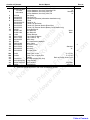
Part Number Listing .................................................................................................................... 31
Part Number/Serial Number Location...................................................................................................31
Arms Part Number Configuration..........................................................................................................31
Roller Part Number Configuration.........................................................................................................31
Illustrated Parts List ..............................................................................................................................32
Arms..................................................................................................................................................32
Electronics.........................................................................................................................................34
052547-301r6
Printed in USA
May, 2009
PROPRIETARY STATEMENT
The Eclipse Patio Awning is a product of Carefree of Colorado, located in Broomfield, Colorado, USA. The
information contained in or disclosed in this document is considered proprietary to Carefree of Colorado.
Every effort has been made to ensure that the information presented in the document is accurate and
complete. However, Carefree of Colorado assumes no liability for errors or for any damages that result
from the use of this document.
M
an
N u
or al
th C
ht
w om
es
tp
pl
:// P
t
R im
w rin
V e
w te
n
w
S
.n d F
up ts
w r
o
p
rv om
ly f
su
pp
ly
.c
om
The information contained in this manual pertains to the current configuration of the models listed on the
title page. Earlier model configurations may differ from the information given. Carefree of Colorado
reserves the right to cancel, change, alter or add any parts and assemblies, described in this manual,
without prior notice.
Carefree of Colorado agrees to allow the reproduction of this document for use with Carefree of Colorado
products only. Any other reproduction or translation of this document in whole or part is strictly prohibited
without prior written approval from Carefree of Colorado.
SAFETY INFORMATION
WARNING
A WARNING INDICATES A POTENTIALLY HAZARDOUS SITUATION WHICH, IF NOT AVOIDED, COULD RESULT IN
DEATH OR SERIOUS INJURY AND/OR MAJOR PROPERTY DAMAGE.
CAUTION
A CAUTION INDICATES A POTENTIALLY HAZARDOUS SITUATION THAT MAY CAUSE MINOR TO MODERATE
PERSONAL INJURY AND/OR PROPERTY DAMAGE. IT MAY ALSO BE USED TO ALERT AGAINST UNSAFE PRACTICES.
NOTE: A note indicates further information about a product, part, or step.
Tip:
A tip provides helpful suggestions.
Safety Notes:
•
•
•
•
Always disconnect battery or power source before working on or around the electrical system.
Always wear appropriate safety equipment (i.e. goggles).
Always use appropriate lifting devices and/or helpers when lifting or holding heavy objects.
When using fasteners, use care to not over tighten. Soft materials such as fiberglass and aluminum
can be "stripped out" and lose the ability to grip and hold.
Reference Publications located @ www.carefreeofcolorado.com:
052547-001
052547-021
052547-031
052547-101
052547-201
052547-211
052547-301
052987-002
052526-001
Eclipse Arms and Canopy After Market Installation Manual
Eclipse Arms and Canopy OEM Installation Manual
Eclipse Arms and Canopy OEM Installation Manual - Winnebago
Eclipse Arms Upgrade for One-Touch
Eclipse Owner's Manual
Eclipse Owner's Manual - Winnebago
Eclipse Service Manual
WindSmart Installation & Operation Manual
Direct Response Installation Manual
Carefree of Colorado
a Scott Fetzer company
2145 W. 6th Avenue Broomfield, CO 80020
www.carefreeofcolorado.com
Table of Contents
Carefree of Colorado
Service Manual
ECLIPSE
PRODUCT OVERVIEW
The Eclipse Patio Awning uses unique “scissor” style arms that do not require vertical ground support. The
arms provide easy to use pitch adjustment—simply push together the pins on the arms, snap into the hole
set desired, and the pitch is set! The pitch can be left in any position and the Eclipse will roll up completely!
When the awning is rolled back out, it rolls out to the pitch setting previously set.
The awning rollbar and arms are made from light weight, no-rust aluminum. The awning fabric is offered in
either heavy weight vinyl or the Sunbrella® fabric, one of the most durable, strongest, weather-resistant
and fade resistant fabrics on the market.
M
an
N u
or al
th C
ht
w om
es
tp
pl
:// P
t
R im
w rin
V e
w te
n
w
S
.n d F
up ts
w r
o
p
rv om
ly f
su
pp
ly
.c
om
Two auto-retract systems are used for the hardwired Eclipse awning, WindSmart (discontinued) and Direct
Response. The system may be installed as part of the original motorized awning installation or as an upgrade to
an existing motorized awning. An auto-retract system offer unique features not available with standard electronics:
•
Full-Extend – Press and release the control to extend, the awning extends completely.
necessary to hold the button when opening.
•
Full-Retract – Press and release the control to retract, the awning retracts completely. It is not. It is not
necessary to hold the button when closing.
•
Auto-Retract – The awning can be set to automatically close when windy conditions occur.
•
Remote Control – The operator can conveniently operate the awning from any location with a wireless
remote control.
It is not
Eclipse Patio Awning Specifications:
ECLIPSE XL
ECLIPSE UNIVERSAL
8 foot
9 foot
Maximum Extension:
12 - 21 feet
12 - 21 feet
Length:
approximately 12 inches
approximately 13.5 inches
Drop @ Min. Pitch:
approximately 40 inches
approximately 45 inches
Drop @ Max Pitch:
Gas Shock
Gas Shock
Extend Actuation:
Motorized roll up
Motorized roll up w/ supplemental spring tension
Retract Actuation:
Motorized roll out/in
Position Control:
12VDC (operating range 10VDC to 14VDC) 1
Power Requirements:
15 amp
Circuit Rating:
Motor and controls are routed and hardwired into the vehicle’s 12V system
Power Source:
OR 14.4V NiCD Battery (rechargeable) (discontinued)
Battery Charger:
Input: 10VDC to 18VDC Time to Charge 2: 2 Hours
Electrical override system (external power source)
Emergency Retract:
Eclipse Patio Awning Options:
Alumaguard Awning Wrap 3
Uniguard Awning Wrap 3
SunBlocker
WindSmart Auto-Retract System 4 (discontinued)
12V Direct Response Auto-Retract System 4
Remote Control 5
NOTES:
1. Installation with optional SunBlocker shade requires a minimum power source of 12VDC (operating range
12VDC to 14VDC)
2. Charge time is approximate requirement for a fully discharged battery to be fully charged.
3. Selected at time of initial order.
4. Windsmart and Direct Response Installations are not available with the Universal AM Eclipse w/ Battery
5. Remote Control available with auto-retract installations only
052547-301r6
1
Table of Contents
ECLIPSE
Service Manual
Carefree of Colorado
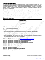
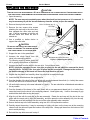
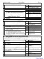
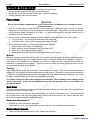
CANOPY REPLACEMENT
FOR UNIVERSAL ECLIPSE
#10 x 5/8 Screw (qty: 4)
Idler
End Cap
End Cap
Roller Assembly
Motor
Detail A
Align Slots
M
an
N u
or al
th C
ht
w om
es
tp
pl
:// P
t
R im
w rin
V e
w te
n
w
S
.n d F
up ts
w r
o
p
rv om
ly f
su
pp
ly
.c
om
Align Slots
Alumaguard
Detail B
Upper Bracket
Uniguard
Detail C
(After Market Installations)
Trim Polycord
1” From Fabric
Trim Polycord
1” From Fabric
Feeder
1-Piece Fabric
Feeder
Detail D
2-Piece Fabric
E0052
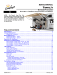
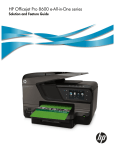
Figure 1. Canopy Replacement - Universal Eclipse.
1. Remove the canopy retaining screws in the awning rail.
2. Extend the awning out completely.
3. Set the awning to the maximum pitch.
4. Remove the screws that attach the end caps to the roll bar and save.
5. While holding the roll bar up, pull the roll bar out of the end cap of the motor head.
CAUTION
DO NOT ALLOW THE ROLL BAR TO DROP TOWARD THE GROUND. THE TWISTING MOTION CAN CAUSE SERIOUS
DAMAGE TO THE IDLER ARM.
6. Support the roll bar; pull the roll bar out of the end cap of the idler head.
7. Allow the fabric and roll bar to hang down on the side of the RV. Use care not to scratch the side of the RV.
8. Mark the slots that the current fabric is in then remove any fabric retaining screws in the roll bar and
slide the roll bar off the fabric.
9. Determine the type of canopy replacement:
• If replacing a full fabric canopy or canopy with Alumaguard or canopy with Uniguard: For arms using
an upper mounting bracket, it will be necessary to remove the upper bracket from one side. After
removing the bracket brace the arm using scaffolding or similar support.
CAUTION
THE LOWER MOUNTING SCREWS FOR ARMS USING THE UPPER BRACKET MAY NOT BE MOUNTED INTO STRUCTURAL
MEMBERS OF THE COACH WALL. FAILURE TO SUPPORT THE ARM CAN RESULT IN DAMAGE TO THE COACH WALL.
• For canopy only replacement for units with Alumaguard: The fabric is crimped into the aluminum slat.
Use a large flat screw driver or similar tool to spread open the crimp on both sides of the fabric.
• For canopy only replacement for units with Uniguard: Remove the retaining screws from both sides
of the Uniguard.
2
052547-301r6
Table of Contents
Carefree of Colorado
Service Manual
ECLIPSE
10. Slide the fabric out of the awning rail.
11. Clean and deburr the roll bar slots and awning rail/Alumaguard/Uniguard as required.
previously done, spread open the awning rail track to facilitate inserting the new fabric.
If
not
Tip: Lightly spraying the slots with a dry silicone lubricant will help the fabric slide into the slot without
staining the material.
12. Unfold the replacement fabric then slide the new fabric into the awning rail/Alumaguard/Uniguard.
Center the fabric and install any fabric retaining screws removed previously. Allow the fabric to hang
down the side of the coach.
For Alumaguard installations: Use a pair of side cutters or similar tool and crimp the aluminum.
Use care to not bend or distort the aluminum slats.
M
an
N u
or al
th C
ht
w om
es
tp
pl
:// P
t
R im
w rin
V e
w te
n
w
S
.n d F
up ts
w r
o
p
rv om
ly f
su
pp
ly
.c
om
•
NOTE: While the awning fabric is fairly robust, care must be taken not to snag it on the awning rail.
13. Position the fabric feeders on the roll bar. Be sure to use the same slots as the old canopy.
14. Slide the rollbar on to the new fabric.
removed previously.
Center the fabric and install any fabric retaining screws
15. Remove the feeders.
16. If removed, install the upper mounting bracket.
17. Lift and align the roller assembly with the end cap on the motorized arm assembly. Rotate the end cap
until the slot in the cap aligns with the empty slot in the roller assembly, and then press the roller
assembly fully into the cap. The end cap must seat squarely over the end of the roller assembly when
complete.
NOTE: The roller assembly must be oriented with the fabric going over the roller toward the
coach wall.
18. Secure the end cap to the roll bar using two #10 square-drive screws.
19. Repeat steps 17 and 18 to attach the idler arm assembly to the roll bar.
20. Visually check that the fabric is squarely mounted. Adjust as required.
21. Roll the awning in and out several times to make sure that the fabric is square on the rollbar.
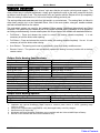
22. Secure the canopy to the awning rail using one, #6 x 3/8" hex head screw at both sides of the awning.
Awning Rail
Fabric
1"
Polyrod
#6 x 3/8
Screw
Awning Rail
Soft Connect
Uniguard
1"
Polyrod
#6 x 3/8
Screw
Awning Rail
Alumaguard
Fabric
#6 x 3/8
Screw
E0014
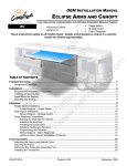
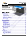
Figure 2. Securing the Fabric.
22.1.
For vinyl awnings, place screw through awning rail, polyrod and canopy approximately 1” in from
the end of the fabric.
22.2.
For Uniguard awnings, place screw through awning rail, polyrod and the soft connect material
approximately 1" in from the end of the fabric.
22.3.
For Alumaguard awnings, place screw on the outer edge of the Alumaguard (not through the
Alumaguard).
For Alumaguard installations, go to "Installing the Alumaguard Tractioners" on page 6.
052547-301r6
3
Table of Contents
ECLIPSE
Service Manual
Carefree of Colorado
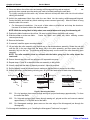
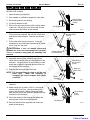
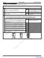
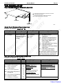
FOR ECLIPSE XL
This procedure applies to the XL Model only. The idler incorporates a roll bar spring to supplement the
closing power of the motor. In the closed position, the spring has no winds; the number of winds increase
as the awning extends. It will be necessary to remove the spring temporarily to change the canopy.
#10 x 5/8 Screw (qty: 4)
Idler
End Cap
End Cap
M
an
N u
or al
th C
ht
w om
es
tp
pl
:// P
t
R im
w rin
V e
w te
n
w
S
.n d F
up ts
w r
o
p
rv om
ly f
su
pp
ly
.c
om
Roller
Assembly
Motor
Align Empty Slots
Detail A
Alumaguard
Detail B
Upper Bracket
(After Market Installations)
Uniguard
Detail C
Trim Polycord
1” From Fabric
Feeder
1-Piece Fabric
Detail D
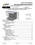
Figure 3. Canopy Replacement - Eclipse XL.
1.
2.
3.
4.
Trim Polycord
1” From Fabric
Feeder
2-Piece Fabric
E0052a
Remove the canopy retaining screws in the awning rail.
Follow the instructions for "Removing the Spring" on page 11.
Remove the screws that attach the motor head end cap to the roll bar and save.
While supporting the roll bar, pull the roll bar out of the end cap of the motor head. It may be necessary
to slide the canopy in the awning rail about 2"-3" for the roll bar to clear the end cap.
CAUTION
THE ARM IS UNDER TENSION FROM THE GAS SHOCK. WHEN THE ROLLBAR IS DISENGAGED FROM THE END CAP,
THE ARM WILL EXTEND FROM THE GAS SHOCK TENSION. USE EXTREME CARE AND HOLD THE ARM AND LET IT
EXTEND. IT WILL BE NECESSARY TO HAVE AT LEAST ONE OTHER PERSON HOLDING THE MOTOR ARM.
5. Allow the fabric and roll bar to hang down on the side of the coach.
6. Mark the slots that the current fabric is in then remove any fabric retaining screws and slide the roll bar
off the fabric.
7. Determine the type of canopy replacement:
• If replacing a full fabric canopy or canopy with Alumaguard or canopy with Uniguard: For arms using
an upper mounting bracket, it will be necessary to remove the upper bracket from one side. After
removing the bracket brace the arm using scaffolding or similar support.
CAUTION
THE LOWER MOUNTING SCREWS FOR ARMS USING THE UPPER BRACKET MAY NOT BE MOUNTED INTO STRUCTURAL
MEMBERS OF THE COACH WALL. FAILURE TO SUPPORT THE ARM CAN RESULT IN DAMAGE TO THE COACH WALL.
• For canopy only replacement for units with Alumaguard: The fabric is crimped into the aluminum slat.
Use a large flat screw driver or similar tool to spread open the crimp on both sides of the fabric.
• For canopy only replacement for units with Uniguard: Remove the retaining screws from both sides
of the Uniguard.
4
052547-301r6
Table of Contents
Carefree of Colorado
Service Manual
ECLIPSE
8. Slide the fabric out of the awning rail/Alumaguard/Uniguard.
9. Clean and deburr the roll bar slots and awning rail/Alumaguard/Uniguard as required. If not previously
done, spread open the awning rail track to facilitate inserting the new fabric.
Tip: Lightly spraying the slots with a dry silicone lubricant will help the fabric slide into the slot without
staining the material.
10. Unfold the replacement fabric then slide the new fabric into the awning rail/Alumaguard/Uniguard.
Center the fabric and install any fabric retaining screws removed previously. Allow the fabric to hang
down the side of the coach.
For Alumaguard installations: Use a pair of side cutters or similar tool and crimp the aluminum. Use
care to not bend or distort the aluminum slats.
M
an
N u
or al
th C
ht
w om
es
tp
pl
:// P
t
R im
w rin
V e
w te
n
w
S
.n d F
up ts
w r
o
p
rv om
ly f
su
pp
ly
.c
om
•
NOTE: While the awning fabric is fairly robust, care must be taken not to snag it on the awning rail.
11. If removed, install the upper mounting bracket.
12. Position the fabric feeders on the roll bar. Be sure to use the same slots as the old canopy.
13. Slide the rollbar onto the new fabric.
removed previously.
Center the fabric and install any fabric retaining screws
14. Remove the feeders.
15. Lift and align the roller assembly with the end cap on the motorized arm assembly. Rotate the end cap
until the slot in the cap aligns with the empty slot in the roller assembly, and then press the roller
assembly fully into the cap. The end cap must seat squarely over the end of the roller assembly when
complete.
NOTE: On early units, a spider bracket was inside the end cap to hold the rollbar in position with
the drive shaft. The newer end caps no longer require the use of the spider.
16. Secure the end cap to the roll bar using two #10 square-drive screws.
17. Insert the idler assembly spring into the roll bar then rotate the end cap until the slot in the cap aligns
with the empty slot in the roll bar. Press the end cap fully on to the rollbar and secure using two #10
square drive screws.
18. With the awning open, it is necessary to add winds to the spring.
To add winds, firmly grasp the
mounting frame and rotate over the top and away from the coach. To hold the frame, use vice grips.
NOTE: One complete revolution equals one wind. One wind must be added for every 11 inches
that the awning is open. With the awning fully extended, total number of winds equals 10.
19. (Refer to Figure 8 on page 11) Place the idler assembly in position over the mounting bolt. Ensure that
the spacer-washers are all accounted for.
NOTE: It will be necessary to collapse and hold the arm to match the roller position.
20. Secure using the washer and lock nut removed previously.
but the idler head should be able to swivel by hand.
The nut should be tightened until snug
21. Attach the rear cover to the motor assembly using the large screw removed previously.
22. Attach the front cover using the small screws removed previously.
23. Visually check that the fabric is squarely mounted without any wrinkles. Adjust as required.
24. Roll the awning in and out several times to make sure that the fabric rolls squarely onto the rollbar.
052547-301r6
5
Table of Contents
ECLIPSE
Service Manual
Carefree of Colorado
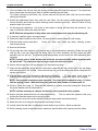
25. Secure the canopy to the awning rail using one, #6 x 3/8" hex head screw at both sides of the awning.
Awning Rail
1"
Fabric
Polyrod
1"
Awning Rail
Soft Connect
#6 x 3/8
Screw
Uniguard
Polyrod
Awning Rail
#6 x 3/8
Screw
#6 x 3/8
Screw
Alumaguard
Fabric
M
an
N u
or al
th C
ht
w om
es
tp
pl
:// P
t
R im
w rin
V e
w te
n
w
S
.n d F
up ts
w r
o
p
rv om
ly f
su
pp
ly
.c
om
E0014
Figure 4. Securing the Fabric.
25.1.
For vinyl awnings, place screw through awning rail, polyrod and canopy approximately 1” in from
the end of the fabric.
25.2.
For Uniguard awnings, place screw through awning rail, polyrod and the soft connect material
approximately 1" in from the end of the fabric.
25.3.
For Alumaguard awnings, place screw on the outer edge of the Alumaguard (not through the
Alumaguard).
INSTALLING THE TRACTIONERS
The tractioners are used with the alumaguard metal fabric wrap and uniguard with vinyl fabrics.
Keeper
1/4" Gap
A
Alumaguard or
Uniguard
Position Tractioner under
Alumaguard/Uniguard
Place Screw Between
Slots on Roller
View A-A
(Alumaguard)
1/4" Gap
A
Place Screw Between
Slots on Roller
View A-A
(Uniguard w/ Vinyl Fabric)
E0058
Figure 5. Installing the Alumaguard Tractioner.
1. Partially extend the awning until the Alumaguard/Uniguard is extended with the edge on the roll bar as shown.
2. Unlock the keeper and wrap the tractioner around the roller tube.
3. Position the tractioner under the Alumaguard/Uniguard with a 1/4” gap between the metal wrap and
tractioner. Lock the keeper.
4. Repeat for the other end of the rollbar.
5. Extend the awning to verify that the tractioners are lifting the metal wrap up and over the roller assembly.
6. To secure the tractioner, drill a 1/8” hole through the tractioner and rollbar; roughly center the hole
between two slots of the rollbar.
7. Secure with one (1) #10 square drive screw.
IMPORTANT NOTE: Over time and use, the awning fabric may stretch. When this occurs the
position of the tractioner relative to the metal wrap may change. It may be necessary to remove the
screw and adjust the position of the tractioners (both sides). It will be necessary to drill new holes
(step 6) before securing with the screw.
6
052547-301r6
Table of Contents
Carefree of Colorado
Service Manual
ECLIPSE
MOTOR REPLACEMENT
CAUTION
ALWAYS DISCONNECT THE BATTERY OR POWER SOURCE BEFORE WORKING WITH ANY ELECTRICAL COMPONENTS.
Two methods are used for replacing the Eclipse motor. 1) Replacing the motor if the awning is extended
(fully or partially) and 2) Replacing the motor if the awning is fully closed.
M
an
N u
or al
th C
ht
w om
es
tp
pl
:// P
t
R im
w rin
V e
w te
n
w
S
.n d F
up ts
w r
o
p
rv om
ly f
su
pp
ly
.c
om
REPLACING THE MOTOR - AWNING EXTENDED
Motor - Black Wire
Cable - Black Wire
Motor - Red Wire
Cable - Red Wire
Motor Head
3/8-16 Lock Nut
1
1
Rear Cover
3/8-16 x 6 Bolt
#10 x 5/8 Screw
(qty: 2)
Spacers
(qty: 11)
Front Cover
NOTE:
1
Wire color from the cable
may deviate on some models.
Standard Color Deviation Color
Red
Yellow
Black
Brown
E0049
Figure 6. Motor Replacement - Awning Extended.
1. For convenience, lower the awning to the maximum pitch setting.
2. On the motorized side, remove the two square drive screws attaching the end cap to the roll bar then
separate the roll bar from the end cap. It will be necessary to hold the roll bar and both arms in
position.
CAUTION
THE ARMS ARE UNDER TENSION FROM THE GAS SHOCK. WHEN THE ROLL BAR IS SEPERATED, BOTH ARMS WILL
EXTEND. USE EXTREME CARE AND HOLD THE ARMS IN POSITION. IT WILL BE NECESSARY TO HAVE AT LEAST ONE
OTHER PERSON HOLDING THE IDLER ARM.
3. Hold on to the motor arm and allow it to extend to its maximum position.
4. Hold on to the idler arm and roll bar and allow the arm to extend to its maximum position while allowing
the fabric to unroll from the roll bar.
CAUTION
FOR XL AWNINGS: THE IDLER HEAD HAS A ROLL BAR SPRING INCORPORATED TO SUPPLEMENT THE CLOSING
POWER OF THE MOTOR. IN THE CLOSED POSITION, THE SPRING HAS NO WINDS; THE WINDS INCREASE AS THE
AWNING IS OPENED. WHEN THE ARM IS FREED THE ARM WILL OPEN/CLOSE UNTIL THE SPRING WIND TENSION
(CLOSE) EQUALS THE GAS SHOCK TENSION (OPEN). ALLOW THE ARM TO COME TO REST AT THE EQUALIZATION
POINT. DURING ASSEMBLY COLLAPSE AND HOLD THE MOTOR ARM TO MATCH THE XL IDLER ARM POSITION.
5. Use a ladder or other device support the roll bar.
CAUTION
DO NOT ALLOW THE ROLL BAR TO DROP TOWARD THE GROUND. THE TWISTING MOTION CAN CAUSE SERIOUS
DAMAGE TO THE IDLER ARM.
6. On the right hand arm remove the front cover by removing the six (6) smaller screws from the back of
the motor head. Save cover and screws.
052547-301r6
7
Table of Contents
ECLIPSE
Service Manual
Carefree of Colorado
7. Disconnect the motor and cable wires from inside the rear cover. Carefully note the location of each
wire.
8. Remove the rear cover by removing the one (1) large screw from the back of the motor head. Save
cover and screw.
9. Loosen and remove the 3/8-16 lock nut from the mounting bolt. Make note of the number and order of
the spacer-washers between the arm mounting block and the motor head.
M
an
N u
or al
th C
ht
w om
es
tp
pl
:// P
t
R im
w rin
V e
w te
n
w
S
.n d F
up ts
w r
o
p
rv om
ly f
su
pp
ly
.c
om
Tip: When the nut is removed, the bolt will slide out of the arm mounting block inside the arm channel.
Placing tape on the head of the mounting bolt and the spacers will prevent them from falling out when
the nut and motor are removed.
10. Remove the motor assembly. The motor assembly consists of the motor, mounting frame, gears, shaft
and roller end cap.
11. Place the new motor assembly in position over the mounting bolt.
are all accounted for.
12. Secure using the washer and lock nut removed previously.
but the motor head should be able to swivel by hand.
Ensure that the spacer-washers
The nut should be tightened until snug
13. Attach the rear cover to the motor assembly using the large screw removed previously.
14. Attach the motor and cable wires to the terminals inside the rear cover.
NOTE: FOR XL AWNINGS: Before attaching the roll bar to the end cap, collapse and hold the motor
arm to match the idler arm position. Ensure that the fabric is rolled up evenly on the roll bar.
15. Align the roll bar with the end cap on the motorized arm assembly.
Rotate the end cap until the slot
in the cap aligns with the empty slot in the roller assembly, and then press the roller assembly fully into
the cap. The end cap must seat squarely over the end of the roller assembly when complete.
NOTE: On early units, a spider gear inside the end cap is used to hold the rollbar in position
with the drive shaft. The replacement end cap no longer requires the use of the spider.
16. Secure the end cap to the roller assembly using two #10 x 5/8 square-drive screws.
17. Restore power and test operation.
If the awning moves in the wrong direction (i.e. extends when
retract is pushed) reverse only the two motor wires in the rear cover.
18. Attach the front cover using the small screws removed previously.
8
052547-301r6
Table of Contents
Carefree of Colorado
Service Manual
ECLIPSE
REPLACING THE MOTOR –AWNING CLOSED
This procedure will require replacing the front and rear motor covers in addition to the motor assembly.
Rear Cover
(ref)
Motor Attach
Bolts & Nuts
Motor Head
Motor (ref)
M
an
N u
or al
th C
ht
w om
es
tp
pl
:// P
t
R im
w rin
V e
w te
n
w
S
.n d F
up ts
w r
o
p
rv om
ly f
su
pp
ly
.c
om
Front Cover
(ref)
3/8-16 Lock Nut
Motor - Black Wire
Cable - Black Wire
Motor - Red Wire
Cable - Red Wire
Rear Cover
3/8-16 x 6 Bolt
#10 x 5/8 Screw
(qty: 2)
Spacers
(qty: 11)
Front Cover
1
1
NOTE:
1
Wire color from the cable
may deviate on some models.
Standard Color Deviation Color
Red
Yellow
Black
Brown
E0049a
Figure 7. Motor Replacement - Awning Closed.
1. Place a large flat blade screwdriver or similar tool in the seam between the front and rear covers. Using
a twisting and prying motion, break the covers off. It may be necessary to use a hammer and lightly tap
the screwdriver into the plastic to establish a starting point.
Tip: Start at the bottom and work around the seam until the covers are off.
2. Disconnect the motor and cable wires from inside the rear cover. Carefully note the location of each wire.
3. Firmly hold the motor and idler arms up while removing the three (3) motor attach bolts and nuts.
4. Remove the motor from the motor mounting frame.
CAUTION
THE ARMS ARE UNDER TENSION FROM THE GAS SHOCKS. WHEN THE MOTOR IS DISENGAGED FROM THE GEARS,
THE ROLL BAR WILL BE ABLE TO FREE SPIN AND BOTH ARMS WILL EXTEND FROM THE GAS SHOCK TENSION. USE
EXTREME CARE AND HOLD THE ARMS IN POSITION. IT WILL BE NECESSARY TO HAVE AT LEAST ONE OTHER
PERSON HOLDING THE IDLER ARM.
5. While holding on to the arms and roll bar allow the awning to extend to the maximum position; the fabric
will unroll from the roll bar.
CAUTION
FOR XL AWNINGS: THE IDLER HEAD HAS A ROLL BAR SPRING INCORPORATED TO SUPPLEMENT THE CLOSING
POWER OF THE MOTOR. IN THE CLOSED POSITION, THE SPRING HAS NO WINDS; THE WINDS INCREASE AS THE
AWNING IS OPENED. WHEN THE ARM IS FREED THE ARM WILL OPEN/CLOSE UNTIL THE SPRING WIND TENSION
(CLOSE) EQUALS THE GAS SHOCK TENSION (OPEN). ALLOW THE ARM TO COME TO REST AT THE EQUALIZATION
POINT. DURING ASSEMBLY COLLAPSE AND HOLD THE MOTOR ARM TO MATCH THE XL IDLER ARM POSITION.
6. On the right hand arm remove any pieces of the front and rear covers. Remove the cover's attaching
screws and save.
052547-301r6
9
Table of Contents
ECLIPSE
Service Manual
Carefree of Colorado
7. Remove the two square drive screws attaching the end cap to the roll bar, separate the roll bar and end
cap. It will be necessary to hold the roll bar and motor arm. Allow the arm to extend out.
8. Use a ladder or other device support the roll bar.
CAUTION
DO NOT ALLOW THE ROLL BAR TO DROP TOWARD THE GROUND. THE TWISTING MOTION CAN CAUSE SERIOUS
DAMAGE TO THE IDLER ARM.
M
an
N u
or al
th C
ht
w om
es
tp
pl
:// P
t
R im
w rin
V e
w te
n
w
S
.n d F
up ts
w r
o
p
rv om
ly f
su
pp
ly
.c
om
9. Loosen and remove the 3/8-16 lock nut from the mounting bolt. Make note of the number and order of
the spacer-washers between the arm mounting block and the motor head.
Tip: When the nut is removed, the bolt will slide out of the arm mounting block inside the arm channel.
Placing tape on the head of the mounting bolt and the spacers will prevent the bolt and the spacers
from falling out when the nut and motor are removed.
10. Remove the rest of the motor assembly. The motor assembly consists of the motor, mounting frame,
gears, shaft and roller end cap.
11. Place the new motor assembly in position over the mounting bolt. Ensure that the spacer-washers are
all accounted for.
12. Secure using the washer and lock nut removed previously. The nut should be tightened until snug but
the motor head should be able to swivel by hand.
13. Attach the rear cover to the motor assembly using the large screw removed previously.
14. Attach the motor and cable wires to the terminals inside the rear cover.
NOTE: FOR XL AWNINGS: Before attaching the roll bar to the end cap, collapse and hold the motor
arm to match the idler arm position. Ensure that the fabric is rolled up evenly on the roll bar.
15. Align the roll bar with the end cap on the motorized arm assembly.
Rotate the end cap until the slot
in the cap aligns with the empty slot in the roller assembly, and then press the roller assembly fully into
the cap. The end cap must seat squarely over the end of the roller assembly when complete.
NOTE: On early units, a spider gear was inside the end cap to hold the rollbar in position with
the drive shaft. The replacement end cap no longer requires the use of the spider.
16. Secure the end cap to the roller assembly using two #10 x 5/8 square-drive screws.
17. Restore power and test operation. If the awning moves in the wrong direction (i.e. extends when retract
is pushed) reverse only the two motor wires in the rear cover.
18. Attach the front cover using the small screws removed previously.
10
052547-301r6
Table of Contents
Carefree of Colorado
Service Manual
ECLIPSE
IDLER/SPRING REPLACEMENT
This procedure applies to the XL Model only. The idler incorporates a roll bar spring to supplement the closing
power of the motor. In the closed position, the spring has no winds; the winds increase as the awning extends.
Rear Cover
Subtract
M
an
N u
or al
th C
ht
w om
es
tp
pl
:// P
t
R im
w rin
V e
w te
n
w
S
.n d F
up ts
w r
o
p
rv om
ly f
su
pp
ly
.c
om
3/8-16 Lock Nut
Tie Arms
In this Area
Mounting Frame
Add
3/8-16 x 6 Bolt
Detail A
#10 x 5/8 Screw
(qty: 2)
Detail B
Spacers
Front Cover
E0051
Figure 8. Idler/Spring Replacement.
REMOVING THE SPRING
1. Extend the awning out approximately 10 inches. This will allow access to the attaching screws for the covers.
2. Tie the arm as shown in Detail A. Use a soft rag or similar material beneath the tie material to prevent
damaging the finish.
CAUTION
THE ARM IS UNDER TENSION FROM THE GAS SHOCK. WHEN THE HEAD IS DISENGAGED FROM THE ROLL BAR, THE
ARM WILL TRY TO EXTEND FROM THE GAS SHOCK TENSION IF THE ARM IS NOT TIED AND SECURED.
3. Remove the six (6) small screws for the front cover and the one (1) large screw that attaches the rear
cover to the frame. Set covers and screws aside and save.
CAUTION
4.
5.
6.
7.
8.
THE SPRING WILL HAVE A MINIMUM OF ONE WIND WHEN THE AWNING IS PARTIALLY OPEN. FIRMLY HOLD THE
IDLER HEAD WHILE DISASSEMBLING. WITH MINIMUM TENSION THE SPRING CAN STILL UNWIND WITH FORCE
THATCAN CAUSE PERSONAL INJURY AND/OR PROPERTY DAMAGE.
Loosen and remove the 3/8-16 lock nut from the mounting bolt. Make note of the number and order of
the spacer-washers between the arm mounting block and the idler head.
Firmly hold the idler head and pull the bolt down to free the head from the arm.
While firmly holding the idler mounting frame, unwind the spring. To unwind, rotate the idler mounting
frame over the top toward the coach.
Remove the square drive screws attaching the end cap to the roll bar and separate the end cap from roll bar.
Pull the idler head and spring out of the roll bar and set aside.
INSTALLING THE SPRING
9. Insert the new spring into the roll bar then rotate the end cap until the slot in the cap aligns with the empty slot
in the roll bar. Press the end cap fully on to the rollbar and secure using two #10 square drive screws.
NOTE: On early units, a spider gear was inside the end cap to hold the rollbar in position with
the drive shaft. The replacement end cap no longer requires the use of the spider.
10. With the awning partially open add one wind to the spring. To add a wind, firmly grasp the mounting
frame and rotate over the top and away from the coach. One complete revolution equals one wind.
NOTE: One wind must be added for every 11 inches that the awning is open.
11. Place the idler assembly in position over the mounting bolt. Ensure that all the spacer-washers are
accounted for.
12. Secure using the washer and lock nut removed previously. The nut should be tightened until snug but
the idler head should be able to turn by hand.
13. Reinstall the idler head covers.
052547-301r6
11
Table of Contents
ECLIPSE
Service Manual
Carefree of Colorado
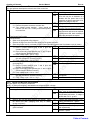
REPLACING THE GAS SHOCK
CAUTION
THE GAS SHOCK HAS APPROXIMATELY 85 LBS OF PRESSURE IN THE CLOSED POSITION. A PRESSURIZED SHOCK
CAN OPEN RAPIDLY WHEN REMOVED OR RELEASED AND CAUSE PERSONAL INJURY AND PROPERTY DAMAGE.
1. Open the awning.
NOTE: The arm may not completely open when the shock has lost pressure or it is removed. It
may be necessary to pull the arm out and away from the vehicle to open the awning.
#10 x 5/8 Screw (qty: 2)
M
an
N u
or al
th C
ht
w om
es
tp
pl
:// P
t
R im
w rin
V e
w te
n
w
S
.n d F
up ts
w r
o
p
rv om
ly f
su
pp
ly
.c
om
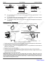
2. Remove the stop bolts and save.
3. Remove the two square drive screws
attaching the end cap to the roller tube,
then separate the roller tube and end
cap. It will be necessary to hold the roll
bar and motor arm. Allow the arm to
extend out.
End Cap
Align Slots
4. Use a scaffold or similar device to
support the roller tube.
Loosen
Stop
Bolts
CAUTION
DO NOT ALLOW THE ROLLER TUBE TO DROP
TOWARD THE GROUND. THE TWISTING MOTION
CAN CAUSE DAMAGE TO THE OTHER ARM.
5. Support the arm in the area shown.
6. Unscrew the shock barrel from the
clevis in the mounting channel.
Tip: Wearing a pair of rubber gloves will
aid in gripping the surfaces of the shock.
Loosen
Set Arm at
Minimum Pitch
Support and Lift in this area
E0054
Figure 9. Replacing the Shock.
7. Unscrew the shaft from the clevis in the arm joint. Set old shock aside.
NOTE: It may be necessary to use vice grips or pliers on the old shock to unscrew the shock
from the clevis. DO NOT use vice grips or pliers on the new shock. Damage to the surface of
the shaft or damage to the barrel can cause the new shock to not work.
8. Unpack the new shock and carefully allow it to extend to its maximum length.
9. Insert the new shock between the upright struts.
10. Coat the threads of the shaft of the new shock with a non-permanent thread lock (i.e. loctite) then screw
the rod into the clevis of the arm elbow. Hand-tighten only.
11. Lift and hold the arm up in the area indicated in Figure 9. The arm should be unfolded and extended as
far as possible.
12. Coat the threads of the barrel of the new shock with a non-permanent thread lock (i.e. loctite) then
screw the barrel into the clevis in the mounting channel. Hand-tighten only. It will be necessary to grip
and hold the shaft while turning the barrel.
13. Align the roll bar with the end cap on the arm assembly. Rotate the end cap until the slot in the cap
aligns with the empty slot in the roller assembly, and then press the roller assembly fully into the cap.
The end cap must seat squarely over the end of the roller assembly when complete.
14. Secure the end cap to the roller assembly using two #10 x 5/8 square-drive screws.
15. Partially retract the awning. It may be necessary to lightly pull down on the lower arm at the mounting
channel until the rollers are past the location of the stop bolts. Always pull down from the bottom of the
arm to avoid pinching.
16. Reinstall the stop bolts removed in step 2.
12
052547-301r6
Table of Contents
Carefree of Colorado
Service Manual
ECLIPSE
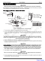
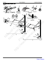
REPLACING THE ARM ROLLERS
Use Kit number R019291-005 for white or
R019251-006 for black.
1. Open the awning completely.
2. Use a ladder or scaffold to support the roller tube.
Drill Out Rivet
Holding Roller
(2 plcs)
3. Disconnect power to the awning.
M
an
N u
or al
th C
ht
w om
es
tp
pl
:// P
t
R im
w rin
V e
w te
n
w
S
.n d F
up ts
w r
o
p
rv om
ly f
su
pp
ly
.c
om
4. Cut the tie bracket in half.
5. Drill out the roll rivets from the roller on both sides
of the arm. Drill only the rivet; do not drill into the
roller mount at the bottom of the channel.
Cut Tie Bracket
E0061a
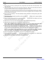
6. Spread the arm channels and hold slightly skewed.
From inside the channels, drill out the 4 rivets that
hold the tie bracket halves. Remove and discard
parts.
Drill Out and Remove
Bracket Rivets
(4 plcs)
7. Pull out the roller from the channel. It may be
necessary to use a flat blade screwdriver or similar
tool to "pop out" the roller.
CAUTION USE A RAG OR SIMILAR PROTECTION
BETWEEN ANY TOOLS AND THE SURFACES OF THE ARMS.
THIS IS TO PREVENT SCRATCHING OR DAMAGING THE
SURFACE.
Remove Roller
From Extrusions
E0061b
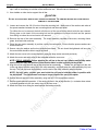
8. Assemble the new roller, standoff and rivet as
shown then insert the roller into the channel of the
extrusion. It may be useful to use a clamp or wide
mouth pair of pliers to squeeze the new roller into
the channel of the extrusion.
Insert Rollers
into Channel
(2 plcs)
9. Slide the arm channels onto the rivets.
Slide Arm
Onto Rivet
NOTE: It is not necessary to crimp or roll the new
roller rivet.
When the assembly is
complete; the rivet is trapped and cannot
come out.
Roller
Standoff
Rivet
E0061c
10. Position the new tie bracket between the arm
channels.
11. Attach using four (4) each 1/4-20 x 1 truss head
screws and nylock nuts. Use the existing rivet
holes in the channels. Before tightening, make
sure that the front of the bracket is parallel with the
front face of the channels.
12. Clean the surface of the bracket then attach the
warning label to the front of the bracket.
13. Remove the roller tube supports and reconnect
power to the awning.
052547-301r6
DANG
Keep
Hand ER
s Cle
ar
Label
1/4-20 Screw
& Nut
(4 plcs)
Tie Bracket
E0061d
13
Table of Contents
ECLIPSE
Service Manual
Carefree of Colorado
DIAGNOSTICS
The following procedures are intended to aid the service technician to logically resolve operational issues
with the mechanical and standard electronics installations.
Common Operational Items
The following items are operational items that may come up as questions during normal operation. These
are also given in the operator's manual.
M
an
N u
or al
th C
ht
w om
es
tp
pl
:// P
t
R im
w rin
V e
w te
n
w
S
.n d F
up ts
w r
o
p
rv om
ly f
su
pp
ly
.c
om
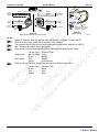
1. The motor has a thermal protection circuit. If the motor overheats, the circuit will shut off the motor.
Wait approximately 15 minutes, operation will return to normal. As an example, this may occur if the
awning is fully closed and retract switch pushed repeatedly, then the awning does not extend.
2. The awning seems to extend and retract slowly. The operational range is 28-35 seconds to extend or
retract. If the power supply is on the low side of the range (10V) the awning will move slower.
3. The awning may appear to move jerkily. When the fabric is rolled out, the Alumaguard or Uniguard
may "bounce" creating a wave like motion in the canopy fabric. This will create the appearance of
moving jerkily.
4. With Uniguard, the awning sticks or hangs up. When Uniguard is installed with a vinyl canopy, the vinyl
will have a tendency to "cling" to the Uniguard when not used over an extended period. Open and
close the awning in short bursts 2 or 3 times, the awning will then open normally.
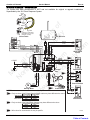
Refer to the appropriate wiring diagram for the system being tested:
STANDARD ELECTRICAL
Wiring diagram – single switch
Wiring diagram – multiple switch
page 22
page 22
AUTO RETRACT SYSTEMS:
Wiring diagram – Windsmart
Wiring diagram – Direct Response
page 23
page 24
Procedures in this section:
Page
STANDARD ELECTRICAL ................................................................................................................... 15
D01
THE AWNING OPERATES IN REVERSE OF THE SWITCH PLATE ...................................................15
D02
THE AWNING DOES NOT EXTEND AND/OR RETRACT .................................................................15
D03
ARM DOES NOT EXTEND OR DOES NOT EXTEND COMPLETELY .................................................17
AUTO RETRACT SYSTEMS ................................................................................................................ 18
D04
THE AWNING OPERATES IN REVERSE OF THE SWITCH PLATE MARKINGS ..................................18
D05
THE AWNING DOES NOT EXTEND AND/OR RETRACT USING THE PATIO SWITCH.........................18
D06A
AWNING DOES NOT AUTO-RETRACT DURING WINDY CONDITIONS -WINDSMART .....................19
D06B
AWNING DOES NOT AUTO-RETRACT DURING WINDY CONDITIONS –DIRECT RESPONSE ..........19
D07
AWNING DOES NOT MOVE WHEN KEY FOB BUTTONS ARE PUSHED ...........................................19
COMMON TEST PROCEDURES ........................................................................................................... 20
14
CT01
TESTING A SWITCH AND HARNESS .........................................................................................20
CT02
TESTING THE CONTROL BOX .................................................................................................21
CT03
TESTING THE BATTERY AND CHARGER ..................................................................................21
052547-301r6
Table of Contents
Carefree of Colorado
Service Manual
ECLIPSE
STANDARD ELECTRICAL
The following procedures are intended to aid the service technician to logically resolve operational issues
with the mechanical and standard electronics installations.
In the charts below, YES is a positive response to the test; NO is a negative response.
D01
THE AWNING OPERATES IN REVERSE OF THE SWITCH PLATE
M
an
N u
or al
th C
ht
w om
es
tp
pl
:// P
t
R im
w rin
V e
w te
n
w
S
.n d F
up ts
w r
o
p
rv om
ly f
su
pp
ly
.c
om
This condition generally occurs during new installations or when major components have been replaced.
Switch mounted OK; go to test B
A Confirm Switch is mounted in correct position and correctly YES
oriented.
Carefully remove the switch, rotate
NO
180 and reinstall in panel. Reconnect
harnesses and retest
Confirm
switch
is
wired
correctly.
Use
the
wiring
diagram
and
Switch wired OK; go to test C
B
YES
confirm the wires to/from the switch to the connector are NO
Rewire the switch according to the
correctly placed.
wiring diagram
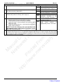
D02
THE AWNING DOES NOT EXTEND AND/OR RETRACT
For Multiple Switch configurations, the Power switch must be ON.
A Check Installation Integrity
Use the wiring diagram and confirm that the components and
wiring are properly installed and connected
B Confirm Power Supply
Is vehicle battery or power source providing 10V to 14V to the
Switch (Power switch for Multiple switch installations) For
battery installations, use test procedure “CT03 Testing the
Battery” on page 21.
C Test Motor Function
1. For installations with an external plug; Disconnect plug.
2. For installations with a single switch; Remove switch plate and
disconnect the motor wires from the switch.
3. For installations with multiple switches, disconnect the
connector from the relay to the motor. If no connector, remove
the butt splices on the red and black wires from the motor. Cap
the wires to prevent shorting
4. Attach jumper leads to the emergency terminals located
on the back of the motor head.
5. Connect the other ends of the jumpers to a 12-18VDC
power source (i.e. drill battery). It may be necessary to try
then reverse the leads on the battery and try again.
6. Does the motor run?
D Test wire continuity between motor and wire ends.
YES
NO
Go to test B
Correct as required
YES
NO
Go to test B
Correct as required
YES
NO
Motor is good, go to test C
Motor is defective - replace
YES
Wire continuity good – reconnect the
wires disconnected in the previous
test then go to test D
Repair as required then reconnect
the wires disconnected in the
previous test.
NO
DO2 continued on next page
052547-301r6
15
Table of Contents
ECLIPSE
Service Manual
Carefree of Colorado
D02 (CONT)
E Test Switch Function - Single switch Installation (this test requires a continuity tester)
M
an
N u
or al
th C
ht
w om
es
tp
pl
:// P
t
R im
w rin
V e
w te
n
w
S
.n d F
up ts
w r
o
p
rv om
ly f
su
pp
ly
.c
om
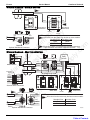
The Patio Switch used in the Single Switch Installation is a center on that is internally crossed-wired that shorts
in the center position to provide dynamic braking for the motor to prevent "drift" when the awning is stopped.
1. Place one lead of tester
Pin:
Center Extend Retract
YES Test OK, all checks pass - go to
on pin 2B. Touch 2nd
step E2
3
N
Y
N
lead to the other pins
6
Y
N
Y
one at a time
5B
Y
N
N
Test Failed; switch defective NO
replace
N = no continuity, Y = continuity
Observe continuity for switch in center position, extend position
and retract position.
2. Place one lead of tester
Pin:
Center Extend Retract
YES Test OK, all checks pass
on pin 5B. Touch 2nd lead
Revaluate problem, cause is not
3
N
N
Y
to the other pins one at a
electrical
6
Y
Y
N
time.
Test Failed; switch defective N = no continuity, Y = continuity
NO
replace
Observe continuity for switch in center position, extend position
and retract position.
(Retract)
(Extend)
6
5B
3
2B
4
1
(ON)
(Retract)
7
6
5
(OFF) 2
1
3
1 (Extend)
Power
Single Switch
F
E0055
Test Switch Function - Multiple switch Installation (this test requires a continuity tester)
1. a. Power Switch: Disconnect the wires from the back of the
YES Test OK, all checks pass - go to
2.
b.
c.
d.
a.
b.
c.
d.
e.
f.
16
Patio
Multiple Switch
switch. Using a continuity tester, place one lead on pin 1.
Place the second lead on pin 5. Put the switch in the OFF
position and measure the continuity. Circuit should be open.
Press the switch ON. Circuit should be closed.
Repeat steps a and b using pins 2 and 6
Test continuity between pins 5 and 6. Circuit should be open.
Patio Switch (test also valid for exterior switch): Using a
continuity tester, place one lead on common pin 3. Place the
second lead on pin 1. Put the switch in the center position
and measure the continuity. Circuit should be open.
Press the switch down (Extend). Circuit should be open.
Press the switch up (Retract). Circuit should be closed.
Move the second lead to pin 7. Put the switch in the center
position and measure. Circuit should be open.
Press the switch down (Extend). Circuit should be closed.
Press the switch up (Retract). Circuit should be open.
NO
step F2
Test Failed; switch defective replace
YES
Test OK, all checks pass
Revaluate problem, cause is not
electrical
NO
Test Failed; switch defective replace
052547-301r6
Table of Contents
Carefree of Colorado
Service Manual
ECLIPSE
D03 ARM DOES NOT EXTEND OR DOES NOT EXTEND COMPLETELY
A Visually confirm motor is working when control switch is pressed. YES
NO
Confirm that the arm channels, pivot points and contact points
are clean and clear of obstructions.
YES
NO
C
If the awning has Alumaguard, check that the tractioners are
installed and positioned correctly (refer to page 6).
YES
NO
M
an
N u
or al
th C
ht
w om
es
tp
pl
:// P
t
R im
w rin
V e
w te
n
w
S
.n d F
up ts
w r
o
p
rv om
ly f
su
pp
ly
.c
om
B
Go to test B
Go to test D02 – Awning Does Not
Extend and/or Retract – page 14.
Go to test C
Clean and Lubricate then retest. If
the arm still hangs up – go to test C
Tractioners OK - Go to test D
Reposition
and
attach
the
tractioners
according
to
the
directions on page 6 and retest.
Shock is defective – replace. See
procedure on page 12.
Shock extends with arm and is
solid.
Shock
pressure
is
approximately 85 lbs. Go to test E.
D
E
1. Open the awning. If the awning arm does not extend,
YES
carefully pull the arm out as the fabric is unrolling.
2. Does the fabric sag when the awning is extended?
NO
3. Inspect the shock. Is there evidence of dirt build up and oil
leaks on the rod?
4. Hand close and open the arm. Is the tension from the shock
mushy, weak or missing?
NOTE: To close the awning by hand, push the head of the
arm toward the coach. Pulling down on the head or roll bar
WILL NOT close the awning.
This step only applies to new Uniguard and Alumaguard installations that do not extend correctly. Check that the
centerline of the roll bar is 3/4" ± 1/4" above the centerline of the awning rail. Refer to 052547-001 Eclipse Arms
and Canopy After Market Installation Manual or 052547-021 Eclipse Arms and Canopy OEM Installation Manual
and reposition the arms as necessary.
052547-301r6
17
Table of Contents
ECLIPSE
Service Manual
Carefree of Colorado
AUTO RETRACT SYSTEMS
The following procedures are intended to aid the service technician to logically resolve operational issues
with the auto-retract installation.
Refer to the appropriate wiring diagram for the system being tested:
In the charts below, YES is a positive response to the test; NO is a negative response.
D04
THE AWNING OPERATES IN REVERSE OF THE SWITCH PLATE MARKINGS
M
an
N u
or al
th C
ht
w om
es
tp
pl
:// P
t
R im
w rin
V e
w te
n
w
S
.n d F
up ts
w r
o
p
rv om
ly f
su
pp
ly
.c
om
The Mode switch must be in the POWER ON or AUTO-RETRACT ON positions.
Switch mounted OK; go to test B
A Confirm Switch is mounted in correct position and correctly
YES
oriented.. The lens or lens caps should be on the bottom of
Carefully remove the switch, rotate
NO
the switch as indicated by the shaded area.
180 and reinstall in panel. Reconnect
harnesses and retest
Switch wired OK; go to test C
B Confirm switch is wired correctly. Use the wiring diagram and
YES
confirm the wires from the switch to the connector are
Rewire the switch according to the
NO
correctly placed.
wiring diagram
Switch and Harness OK; go to test D
C Confirm Operation of PATIO Switch Use test procedure “CT01 YES
Testing a Switch and Harness” on page 20.
Repair or replace as recommended
NO
in procedure and retest
Power and Control Box OK
D Is the control box operating correctly? Use test procedure YES
“CT02 Testing the Control Box” on page 21.
Repair as recommended in
NO
procedure and retest
D05
THE AWNING DOES NOT EXTEND AND/OR RETRACT USING THE PATIO SWITCH
The Mode switch must be in the POWER ON or AUTO-RETRACT ON positions.
Confirm Power Supply Is vehicle battery or power source YES
Go to test B
A
providing 10V to 14V to the control box.
Correct as required
NO
Test Motor Function
Motor is good, go to test C
B
YES
1. Disconnect Motor Plug from control box.
Motor is defective - replace
NO
2. Attach jumper leads to the emergency terminals located
on the back of the motor head.
3. Connect the other ends of the jumpers to a 12-18VDC
power source (i.e. drill battery). It may be necessary to try
then reverse the leads on the battery and try again.
4. Does the awning move?
Wire continuity good – go to test D
C Test wire continuity between motor and control box connector. YES
Repair as required
NO
Switch and harness OK; go to test E
D Confirm Operation of MODE Switch Use test procedure “CT01 YES
Testing a Switch and Harness” on page 19.
Repair or replace as recommended
NO
in procedure and retest
Confirm Operation of PATIO Switch Use test procedure “CT01 YES
Switch and harness OK; go to test F
E
Testing a Switch and Harness” on page 20.
Repair or replace as recommended
NO
in procedure and retest
Is
the
control
box
operating
correctly?
Use
procedure
“CT02
Control box OK; go to test E
F
YES
Testing the Control Box” on page 21.
Repair as recommended in
NO
procedure and retest
18
052547-301r6
Table of Contents
Carefree of Colorado
Service Manual
ECLIPSE
D06A AWNING DOES NOT AUTO-RETRACT DURING WINDY CONDITIONS -WINDSMART
NOTE: The mode switch must be set to Auto-Retract ON
A Confirm that the retract function works using the PATIO switch
YES
NO
B
Test Anemometer
1. Do the anemometer cups spin freely?
Go to step B2
Anemometer defective - replace
Plug the connector into the control
box; Go to “Testing The Control Box”
The circuit stays open or stays closed
or the ohmmeter reads more that
1000ohms (2x or more); go to step
B3
M
an
N u
or al
th C
ht
w om
es
tp
pl
:// P
t
R im
w rin
V e
w te
n
w
S
.n d F
up ts
w r
o
p
rv om
ly f
su
pp
ly
.c
om
2. Test signal from anemometer:
2.1. Remove anemometer connector from control box;
2.2. Place an ohmmeter between pins of connector;
2.3. Have a helper SLOWLY turn the anemometer: Does
the circuit open and close? It should open and close
once for every revolution. When closed, the meter
should read approximately 1000ohms
3. Test the wire continuity between the connector and the
anemometer.
YES
NO
YES
Function works using the switch; go
to test B
Function does not work with switch;
go to procedure D01 on page 17
NO
YES
NO
Continuity OK; replace anemometer
Repair or Replace wires as required
D06B AWNING DOES NOT AUTO-RETRACT DURING WINDY CONDITIONS –DIRECT RESPONSE
NOTE: The mode switch must be set to AUTO-RETRACT ON
A Confirm that the retract function works using the PATIO switch
YES
NO
B
Test Motion Sensor
1. Confirm cable is plugged into connector on box marked
“Motion Sensor”
2. Remove cable from box and inspect connector on cable.
Connector should be wired as shown in the wiring diagram
(page 23 or page 24).
3. Unplug sensor from control box
3.1. Connect a second sensor into control box.
3.2. Set the control switches for the auto retract function
3.3. Hold the second sensor vertically and gently move up
and down.
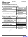
D07
Function works using the switch; go
to test B
Function does not work with switch;
go to procedure D01
YES
NO
YES
NO
Go to step 2
Correct as required and test.
Wired OK, go to step 3
Remove connector and replace
YES
Awning retracts; original sensor
defective - replace
Awning does not retract; control box
defective - replace
NO
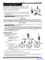
AWNING DOES NOT MOVE WHEN KEY FOB BUTTONS ARE PUSHED
Before continuing, ensure that the system is working correctly at the switch panel. If not, go to DO1" The Awning
Does Not Extend and/or Retract Using the Patio Switch".
NOTE: The Mode switch must be in the POWER ON or AUTO-RETRACT ON positions for the key FOB to work.
Battery OK - Key FOB does not work
A Remove battery from Key FOB and test. Should measure
YES
between 2V-3V.
– go to test B
Replace battery
NO
Confirm
that
the
Receiver
is
programmed
for
the
Key
FOB
If system does not work; go to step C
B
(refer to page 28)
2nd Key FOB works. 1st Key FOB is
C Program a second Key FOB (refer to page 28) and test
YES
defective.
2nd Key FOB does not work; go to
NO
step D
Cable is OK. Confirm that cable is
D Check the cable between the RR24 and Direct Response
YES
control box. As a continuity check, Pin 1 of connector 1 goes
securely plugged in; go to step 4
to Pin 1 of connector 2; pin 2 goes to pin 2; pin 3 goes to pin 3
Repair or Replace as required.
NO
and pin 4 goes to pin 4
System works OK. 1st receiver is
D Replace the RR24 Receiver and test
YES
defective
System does not work. Reinstall 1st
NO
receiver; go to step E
Replace
Auto-Retract
control
box
E
052547-301r6
19
Table of Contents
ECLIPSE
Service Manual
Carefree of Colorado
COMMON TEST PROCEDURES
These common tests are referred to in the diagnostics procedures.
CT01 TESTING A SWITCH AND HARNESS
M
an
N u
or al
th C
ht
w om
es
tp
pl
:// P
t
R im
w rin
V e
w te
n
w
S
.n d F
up ts
w r
o
p
rv om
ly f
su
pp
ly
.c
om
Disconnect the switch harness connectors from the control box and remove the plate and switches from the mounting
surface.
Switch mounted OK; go to test B
A Confirm switch is mounted in correct position and correctly
YES
oriented. The lens or lens caps should be on the bottom of
Carefully remove the switch, rotate
NO
the switch as indicated by the shaded area
180˚
and
reinstall
in
panel.
Reconnect harnesses and retest
Switch wired OK; go to test C
B Confirm switch is wired correctly. Use the wiring diagram and YES
confirm the wires from the switch to the connector are
Rewire the switch according to the
NO
correctly placed.
wiring diagram
C Test the Switch function (this test requires a continuity tester
• Do not remove the wires from the back of the switch. From the numbered terminal of the switch, trace the wire to the
connector; place the tester leads on the connector pins. The pins are not marked on the connector.
• Steps 1 through 5 are for the Patio and Wind Speed Switches. Refer to step 6 for the Mode Switch.
Using a continuity tester, place one lead on common pin (3 for
Circuit(s) are open, go to step 2
YES
Patio, 5 for Windspeed). Place the second lead on pin 1. Put
Circuit(s) are closed (continuity exists);
NO
the switch in the center position and measure the continuity.
switch assy is defective-replace
Move the second lead to pin 7, measure the continuity. Circit
should be open
Place the second lead on pin 1. Press the switch down
Circuit closed; go to step 4
YES
("Extend" for patio, "Lo" for sensitivity). Is circuit closed?
Circuit open, switch defective - replace
NO
Leave the leads in position of step 2. Press the switch up
Circuit open: go to step 4
YES
("Retract" for patio, "Hi" for sensitivity). Is the circuit open?
Circuit closed, switch defective - replace
NO
Move the second lead to pin 7. Press the switch down
Circuit open: go to step 5
YES
("Extend" for patio, "Lo" for sensitivity). Is the circuit open?
Circuit closed, switch defective - replace
NO
Leave the leads in position of step 4. Press the switch up
Circuit closed; go to step 6
YES
("Retract" for patio, "Hi" for sensitivity). Is the circuit closed?
Circuit open, switch defective - replace
NO
For Mode Switch only - Follow steps 1 through 5 using pins 5,
Switch tests OK, return to diagnostic
YES
2 and 8 respectively
Test Failed; switch defective
NO
1
5
7
Wind Speed
20
1
3
7
Patio
1
3
5
7
2
4
6
8
9
10
Mode
WS009a
052547-301r6
Table of Contents
Carefree of Colorado
Service Manual
ECLIPSE
CT02 TESTING THE CONTROL BOX
This test had been developed as a bench test of the control box.
A Test Power
1. Check Fuse
Fuse OK; go to step A2
NO
Replace fuse. If the fuse continues to
blow, this may be an indication of a
situation with the power lines to the
control box or with the control box. If so,
replace fuse and go to step A2
Voltage and Polarity is correct; go to B
YES
M
an
N u
or al
th C
ht
w om
es
tp
pl
:// P
t
R im
w rin
V e
w te
n
w
S
.n d F
up ts
w r
o
p
rv om
ly f
su
pp
ly
.c
om
2. Confirm power to the control box:
2.1. Remove the power connector at control box
2.2. Test voltage across terminal. Value should be
between 10V and 14V. Polarity must match symbols
on control box.
YES
B
YES
NO
Voltage is correct but polarity is
reversed. Reverse wires and retest.
Voltage is less than 10V. Check vehicle
power sources and correct as required.
If power source OK, check continuity to
power plug and repair as required
Test Control Box Function
For these tests:
• Refer to the appropriate wiring diagram
• Remove all plugs from the control box except for the power connector.
• Place the positive lead of a voltmeter on pin B (motor) and the negative lead of voltmeter on pin A (motor).
1. Measure the “Power On” Setting
Voltage OK; go to step B1.4
YES
1.1. Place a jumper between pins 6 and 8 (this will
Control box is defective - replace
NO
simulate power ON)
1.2. Place a second jumper between pins 11 and 12 (this
will simulate the “Retract Function”)
1.3. Does voltage equal –10V to –14V?
1.4. Move the second jumper between pins 12 and 13
Voltage OK; go to step B2
YES
(this will simulate the "Extend Function")
Control box is defective - replace
NO
1.5. Does voltage equal +10V to +14V?
2. Measure the “Auto-Retract On” Setting YES Voltage OK;
Voltage OK; go to step B2.4
YES
go to step B2.4
Control box is defective - replace
NO
2.1. Place a jumper between pins 7 and 8 (this will
simulate “Auto-Retract On”)
2.2. Place a second jumper between pins 11 and 12 (this
will simulate the “Retract Function”)
2.3. Does voltage equal –10V to –14V?
2.4. Move the second jumper between pins 12 and 13
Voltage OK; reconnect plugs and return
YES
(this will simulate the “Extend Function”)
to diagnostic
2.5. Does voltage equal +10V to +14V?
Control box is defective - replace
NO
CT03 TESTING THE BATTERY AND CHARGER
This test applies only to battery installations.
NOTE: for safety and shipping, new batteries are shipped without a charge.
A Test Battery
1. Using a volt meter, test the battery voltage.
YES
NO
B
Test Charger
1. Observe the red and green LEDson the charger. Does
the Green LED flash (charging) then stay on steady
(charge complete)?
2. Jiggle the charger connector in the end cap. Does the
green led flash?
YES
NO
YES
NO
052547-301r6
Voltage measures between 14.5 to 17.0
Volts - return to system diagnostic D01
Voltage mesures less than 14.5V Chage battery and retest. If voltage is
still less than 14.5 V - go to B
If battery still measures below 14.5V,
battery pack defective - replace
Red LED is on - go to step 2
End cap connector is faulty - replace
end cap assembly
Check wires - wires OK, charger
defective - replace
21
Table of Contents
ECLIPSE
Service Manual
Carefree of Colorado
WIRING DIAGRAM - SINGLE SWITCH
1
Motor
A
6
5B
3
2B
4
1
Red
2
M
an
N u
or al
th C
ht
w om
es
tp
pl
:// P
t
R im
w rin
V e
w te
n
w
S
.n d F
up ts
w r
o
p
rv om
ly f
su
pp
ly
.c
om
Black
Front View of
Switch Panel
Carefree of Colorado
Rear View of
Switch Panel
+12VDC
Rear View of Connectors Shown
Red
Red
Motor
Black
1
NOTE:
1
Wire color from the motor may deviate on some models.
Standard Color Deviation Color
Red
Yellow
Black
Brown
Black
N
N
L
Vehicle
Ground
L
Detail A
Optional Wall Mount Connector
2
Terminals 1 and 4 are capped with insulated connectors.
These terminals must remain capped at all times. E0008
Vehicle Wall
WIRING DIAGRAM - MULTIPLE SWITCH
Gray
Yellow
Brown
Gray
Eclipse
Exterior Switch
Relay
Module
Rear View of Connectors Shown
Exterior Switch
Brown
Yellow
6
6
5
2
2
5
4
1
1
4
Gray
Brown
Yellow
Gray
Brown
Yellow
Gray
Brown
Yellow
Red
Black
Blue
White
Brown
Yellow
A
B
Black
Butt Splice
(5 plcs)
Blue
White
Red
Red
Black
Motor
Gray
1
7
Detail A
Alternate Wire Connection
6
5
2
1
3
1
Carefree of Colorado
1
Motor
Front View of
Switch Panel
Rear View of Connectors Shown
Red
Red
Black
Black
Gray
Yellow
Brown
2
1
7
6
5
3
1
2
6
7
3
5
Exterior
Detail B
Switch
Optional Wall Mount Connector
22
Gray
Yellow
Brown
+12VDC
Vehicle
Ground
Rear View of
Switch Panel
NOTE:
1
Wire color from the motor may deviate on some models.
Standard Color
Red
Black
Deviation Color
Yellow
Brown
E0032a
052547-301r6
Table of Contents
Carefree of Colorado
Service Manual
ECLIPSE
WIRING DIAGRAM - WINDSMART
The system has been discontinued in 2007 and not available for original or upgrade installations.
Superseded by the 12V Direct Response System.
Green
Red
Black
Yellow
M
an
N u
or al
th C
ht
w om
es
tp
pl
:// P
t
R im
w rin
V e
w te
n
w
S
.n d F
up ts
w r
o
p
rv om
ly f
su
pp
ly
.c
om
Green
Red
Black
1
3
5
7
2
4
6
8
9
10
Mode Switch
Program
Mode
TO
EYE PORT
on RP24
Phone Cable
Press to Learn
Transmitter
Yellow
Cables are 4-wire RJ11
terminated phone cord
(straight, no twist).
UP
RF Receiver
BLACK
HI 1
BLUE
RED
GROUND
GRN
POWER ON
BLK
WINDSMART ON OR
+12VDC
RED
COM
5
LOW
7
Wind Speed
Switch
14 15 16
2
GRAY
YELLOW
BRN
WIND SPEED
SWITCH
+12V
GROUND
A B
MOTOR
1
2
MODE SWITCH
15
+12VDC
FUSE (15 A)
RR24
(Optional)
PATIO SWITCH
5
6
7
8
RET
11 12 13
7
ANEMOMETER
Ground
B A
EXT 1
COM
3
9 10
Patio Switch
Control
Box
1
GRAY
YELLOW
BROWN
M
Eclipse
Exterior Switch
RED
BLACK
Awning Motor
3
Anemometer
NOTES:
Early versions of the Eclipse Exterior Switch cable may have different wire colors.
1
Current Color Previous Color
Jacket Color: Black or White
Gray
Brown
Black1
Wire Colors:
Gray
Black2
Yellow
Yellow/Green
2
EXT
1
COM
3
RET
7
Additional
Patio Switch
Early versions of the Patio Switch harness may have different wire colors.
Current Color Previous Color
Brown
Black
Gray
Red
Yellow
Blue
3
Wire colors for anemometer are not pin specific.
052547-301r6
WS006a
23
Table of Contents
ECLIPSE
Service Manual
Carefree of Colorado
WIRING DIAGRAM - DIRECT RESPONSE
Ignition Switched
+12VDC
Press to Learn
Transmitter
Program
Mode
M
an
N u
or al
th C
ht
w om
es
tp
pl
:// P
t
R im
w rin
V e
w te
n
w
S
.n d F
up ts
w r
o
p
rv om
ly f
su
pp
ly
.c
om
12VDC
Ground
RF Reciever
TO
EYE PORT
on RP24
Ignition
Lockout
Sensor
(Optional)
2
UP
Splitter
1
Mode Switch
2
4
6
8
9
10
COM
5
LOW
7
BLUE
RED
GROUND
POWER ON
DIR. RES. ON
+12VDC
GRN
BLK
OR
RED
Wind Speed
Switch
Carefree of Colorado
12V DIRECT RESPONSE
CONTROL BOX
PART NO. 060574-003
14 15 16
4
GRAY
YELLOW
BRN
13
12
11
+12VDC
Ground
B A
EXT 1
COM
3
RET
5
6
7
8
1
2
M
HI 1
BLACK
1
3
5
7
7
Patio Switch
Control
Box
RED
BLACK
EXT
1
COM
3
RET
Motion
Sensor
3
BROWN
7
Additional
Patio Switch
YELLOW
GRAY
Exterior
Switch
24
Vehicle
Wall
A
DR005a
052547-301r6
Table of Contents
Carefree of Colorado
Service Manual
ECLIPSE
Green
Red
Black
BROWN
YELLOW
GRAY
From
Exterior
Switch
Rear View of Connectors Shown
3 2 1
RED
5
BLACK 6
From
Motor
BROWN
YELLOW
GRAY
To
Patio Switch
Connector
3
2
1
2
3
6
5
4
4
5
6
9
8
7
7
8
9
1
Yellow
Green
Red
Black
1 2 3
5
6
RED
BLACK
To
Control Box
Yellow
Cables are 4-wire RJ11
terminated phone cord
(straight, no twist).
M
an
N u
or al
th C
ht
w om
es
tp
pl
:// P
t
R im
w rin
V e
w te
n
w
S
.n d F
up ts
w r
o
p
rv om
ly f
su
pp
ly
.c
om
From
Sensor
To Motor
Connector
Phone
Cable
Phone
Cable
Detail A
Optional Wall Mount 9-Pin Connector
Detail B
Phone Cable
DR005b
NOTES:
1
2
3
4
Splitter is used only when the optional Lock-Out Sensor is installed. Connect the RF
receiver directly to the control box if Lock-Out is not installed.
The optional Lock-Out Sensor can only be used with control boxes marked "p/n 060574003". Wires for the sensor are not pin specific.
Early versions of the Eclipse Exterior Switch cable may have different wire colors.
Current Color
Previous Color
Jacket Color:
Black or White Gray
Brown
Black1
Wire Colors:
Gray
Black2
Yellow
Yellow/Green
Early versions of the Patio Switch harness may have different wire colors.
Current Color
Previous Color
Brown
Black
Gray
Red
Yellow
Blue
052547-301r6
25
Table of Contents
ECLIPSE
Service Manual
Carefree of Colorado
WIRING DIAGRAM - DIRECT RESPONSE W/ PRE WIRED HARNESS
OEM Harness (Simplified)
refer to OEM literature for specific harness configuration and details
15
14
13
12
11
10
9
8
7
6
5
4
3
M
an
N u
or al
th C
ht
w om
es
tp
pl
:// P
t
R im
w rin
V e
w te
n
w
S
.n d F
up ts
w r
o
p
rv om
ly f
su
pp
ly
.c
om
Ignition
Switched
+12VDC
12VDC
Ground
From C6
Lock Out Sensor
To C9
Motor
2
1
Power ON/OFF
(OEM switch)
To C8
DR Sensor
Windspeed Switch
(OEM switch)
+12VDC
Patio Switch
(OEM switch)
Sensor
M
Red
Yellow
Power ON/OFF
(OEM switch)
Patio
(OEM switch)
Windspeed
(OEM switch)
12VDC
Connector C1 Pin-Out - Carefree Harness
Ground
From
To
Description
C1 pin 1
C2 pin 2
+12VDC Power
C1 pin 2
C2 pin 1
12VDC Ground
C1 pin 3
C4 pin 1
Patio Switch, Input for Retract
C1 pin 4
C4 pin 2
Patio Switch, Common (DC Ground)
C1 pin 5
C4 pin 3
Patio Switch, Input for Extend
C1 pin 6
C5 pin 1
Wind Speed, Low
C1 pin 7
C5 pin 2
Wind Speed, Common (DC Ground)
C1 pin 8
C5 pin 3
Wind Speed, High
C1 pin 9
C15 “pin 4”
Motion Sensor, Data Signal
C1 pin 10
C15 “pin 3”
Motion Sensor, +12VDC power
refer to Detail B
C1 pin 11
C15 “pin 2”
Motion Sensor, Common (DC Ground)
C1 pin 12
C6 pin 1
Ignition Lockout, Signal Input 1
C1 pin 13
C6 pin 2
Ignition Lockout, Signal Input 2
C1 pin 14
C3 pin 2
Motor, A Input
C1 pin 15
C3 pin 1
Motor, B Input
C8
pin 2 Black
Wall Plug
(ref)
pin 1 Red
C9
Green
Black (not used)
Phone Cable Adaptor
DETAIL A
26
DR031b
052547-301r6
Table of Contents
Carefree of Colorado
Service Manual
ECLIPSE
Carefree Harness
15
14
13
12
11
10
9
8
7
6
5
4
3
WHITE
BLUE
BLACK
BLACK
RED
GREEN
YELLOW
RED
BLUE
BLACK
(1) (2)
13
15 14
10
12 11
98
7
65
4
M
an
N u
or al
th C
ht
w om
es
tp
pl
:// P
t
R im
w rin
V e
w te
n
w
S
.n d F
up ts
w r
o
p
rv om
ly f
su
pp
ly
.c
om
C6
Lock Out
Sensor
32
BLACK
BROWN
YELLOW
GREY
1
2
RED
C1
1
2
1
1
2
3
1
2
3
2
Splitter
1
1
2
3
2
1
3
2
1
1
2
C4
Patio Switch
C2
Power
C5
C15
Windspeed Switch DR Sensor
C3
Motor
Press to Learn
Transmitter
Program
Mode
TO
EYE PORT
on RP24
RF Reciever
UP
C16
RF Receiver &
Lock Out Sensor
#6 x 1/2” Screw
qty: 2
Green
Red
Black
6” Cable
Splitter
(ref)
C6
Yellow
Green
Red
Black
Lock Out Sensor(ref)
C1
Yellow
Carefree of Colorado
12V DIRECT RESPONSE
CONTROL BOX
PART NO. 060574-003
C2
1
2
#6 x 1/2” Screw
qty: 2
3
2
C3
2
3
C7
4
Phone Cable
DETAIL B
C5
C4
1
C16
3
Cables are 4-wire RJ11
terminated phone cord
(straight, no twist).
1
C15
Control
Box
DR031b
052547-301r6
27
Table of Contents
ECLIPSE
Service Manual
Carefree of Colorado
STANDARD SERVICE PROCEDURES
PROGRAMMING THE REMOTE RECEIVER
Early transmitters & receivers operate on a frequency of 418MHz.
Models for 2007 & on operate on 433MHz. The transmitter and receiver
frequencies must match. Identifying the transmitter frequency is
described under the operational notes below.
UP
M
an
N u
or al
th C
ht
w om
es
tp
pl
:// P
t
R im
w rin
V e
w te
n
w
S
.n d F
up ts
w r
o
p
rv om
ly f
su
pp
ly
.c
om
2. Press and release the “Press to Learn Transmitter” button on the
bottom of the receiver box. The receiver is in program mode when
the red light comes on.
Program
Mode
TO
EYE PORT
on RP24
Stop
Press to Learn
Transmitter
1. Power to the control box must be on.
RR
Indicator
Light
3. For Gray Button Key FOBS: Press and release ANY button on the
remote. It is recommended to use the STOP button. The red light
will go out after the receiver learns the remote signal.
Program
Button
DR020
CAUTION
WHEN THE RECEIVER LEARNS THE TRANSMITTER SIGNAL, THE SYSTEM WILL PERFORM THE OPERATION OF THE
BUTTON PRESSED. EXAMPLE: PRESSING AN "EXTEND" BUTTON DURING THE LEARNING PHASE WILL CAUSE THE
AWNING TO EXTEND WHEN THE RECEIVER LEARNS THE SIGNAL. USE CAUTION TO AVOID UNEXPECTED MOVEMENT
BY THE AWNING.
4. For Key FOBS w/ Antenna: Press and release the STOP button on the remote. The red light will go
out after the receiver learns the remote signal.
NOTE: Pressing the stop button will cause the blue up arrow button to default as the close
(retract) function. If a function button is pressed to train the receiver, it will be programmed as
the close (retract) button. Example: Pressing the bottom button will program the bottom button
for retract and the top button as extend.
5. Repeat for each additional remote.
Operational Notes:
1. Transmitter and receiver must match in
frequency (418 MHz or 433 MHz).
1.1. Key FOBS:
1.1.1. The gray button key FOBS
are marked with a label for
418 MHz or 433 MHz.
1.1.2. Key FOBS w/ antenna are
433 Mhz
Rear Label
FCC ID OJM-CMD-KEYX-XXX
315MHz
418MHz 433MHz
FCC ID OJM-CMD-KEYX-XXX
315MHz
418MHz
433MHz
or
433 MHz
433 MHz
ONLY
ONLY
418 MHz
1.2. Receivers
RR24
RR
RR
Version 1
Version 2
1.2.1. 418 MHz receivers are
RR
RR
marked "RR24".
1.2.2. 433 MHz receivers marked
"RR" Version 1 can only be
433 MHz
418 MHz
433 MHz
used with the 433 MHz gray
DR026a
RF Receiver
button Key FOB.
1.2.3. 433 MHz receivers marked "RR" Version 2 can be used with either of the 433 MHz Key FOBS.
Press to Learn
Transmitter
Program
Mode
UP
TO
EYE PORT
on RP24
Program
Mode
Press to Learn
Transmitter
UP
TO
EYE PORT
on RP24
Program
Mode
Press to Learn
Transmitter
TO
EYE PORT
on RP24
RR24
UP
2. The receiver exits the program mode after ten seconds.
3. If the light does not come on above, the memory is full and must be cleared.
4. To clear the memory: press and hold the transmitter learn button for 5 seconds. While holding the button, the
indicator light should be off for the full 5 seconds then come on.
5. The system may be programmed for up to 5 remotes. Additional remotes may be ordered separately.
28
052547-301r6
Table of Contents
Carefree of Colorado
Service Manual
ECLIPSE
BATTERY REPLACEMENT
This procedure only applies to the Universal Eclipse with battery. The Eclipse battery configuration uses
one exterior switch and one rechargeable 14.4V NiCd battery pack mounted in the right arm assembly.
NOTE: For safety and shipping, new batteries are shipped without a charge. It will be necessary to
charge the battery before using. Refer to "Charging the Battery" below.
1. Remove the two socket head cap screws holding the bottom
cover and set aside. Allow the bottom cover to hang down on
the wires.
Facia
M
an
N u
or al
th C
ht
w om
es
tp
pl
:// P
t
R im
w rin
V e
w te
n
w
S
.n d F
up ts
w r
o
p
rv om
ly f
su
pp
ly
.c
om
2. Remove the fascia.
Upper
Bracket
3. Disconnect the battery connector from the switch in the
bottom cover.
4. Pull out the battery and connector. The mounting brackets
are spring clips, use care to not bend or distort the brackets.
5. Thread the connector and wires down along the inside of the
Motor Connector
channel, behind the springs and pins.
(ref)
NOTE: Orient the battery with the wires starting at the
Bottom Cover
(ref) top of the battery pack.
Lower
Bracket
Battery
Connector
#8 x 3/4
Socket Head
Cap Screw
6. Spread the wires apart and route to each side of the lower
bracket.
7. Place the top of the battery into the top bracket.
E0053
Figure 10. Battery Replacement.
8. Snap the bottom of the battery into the bottom bracket.
9. Connect the battery and motor connectors to the end cover with switch.
10. Reinstall the bottom cover and fascia.
Charging the Battery
14.4 V NiCd
Battery Charger
NOTES ABOUT THE BATTERY:
• Always
discharge
the
battery
completely by operating the awning
before recharging. DO NOT charge Exterior
Switch
the battery after every use.
Receptacle
• Always charge the battery fully. Do
12V
not partially charge the battery.
Vehicle Auxiliary
Power Outlet
• Do not operate the awning while the
battery is charging. If it is necessary
to operate the awning before the
battery is fully charged, first
Green Red
disconnect the charger to prevent
LED LED
E0035
possible damage.
Figure 11. Charging the Battery.
• If the awning is operated while the charger is plugged in, the charger will falsely report a full battery
charge. It will be necessary to reset the charger by unplugging the power cord, wait 10 seconds then
reconnect.
• Do not leave the charger plugged into the battery without power cord plugged in. This can cause the
battery to discharge through the charger. Damage to the battery can occur over extended periods.
1. Connect the charger to the vehicle’s 12 volt auxiliary outlet (cigarette lighter).
Operation Mode Green LED Red LED
Battery fast
charging
Flashing
Fast charge
finished
ON
OFF
Battery not
connected
OFF
Flashing
OFF
PN 060511-001
2. Connect the charger to the battery through the battery receptacle. The receptacle is located next to the
switch on the bottom of the right arm.
3. Observe the LEDs located on the side of the charger. When the green LED stays steady on, the
battery is fully charged. Disconnect the charger.
052547-301r6
29
Table of Contents
ECLIPSE
Service Manual
Carefree of Colorado
STANDARD MAINTENANCE
Maintaining a Carefree Awning is easy. Just follow these basic steps:
• Always operate the awning according to the instructions.
• Periodically check that the fasteners are tight. Tighten if necessary.
• Keep the awning fabric and arms clean.
FABRIC CARE
CAUTION
M
an
N u
or al
th C
ht
w om
es
tp
pl
:// P
t
R im
w rin
V e
w te
n
w
S
.n d F
up ts
w r
o
p
rv om
ly f
su
pp
ly
.c
om
DO NOT USE OIL BASED CLEANERS OR ANY CAUSTIC, GRANULATED, OR ABRASIVE TYPE CLEANERS ON YOUR
CAREFREE PRODUCT.
1. One of the best ways to keep the fabric looking good and to delay the need for deep or vigorous
cleanings is to hose fabrics off on a monthly basis with clear water. This practice will help prevent dirt
from becoming deeply imbedded in the fabric. In most environments, a thorough cleaning will be
needed every two to three years.
2. When it’s time for a thorough cleaning, the fabric can be cleaned while still on the awning frame.
• For Vinyl Fabric – Use a soft brush and warm water with soap.
• For Acrylic Fabric – Use a stiff brush and warm water with soap.
3. When cleaning the fabric, it is important to observe the following:
• Always use a natural soap, never detergent.
• Water should be cold to lukewarm, never more than 100°F.
• Air-dry only. Never apply heat to the fabric.
• Always allow the fabric to dry thoroughly before rolling up the awning.
Mildew
Mildew is a fungus growth that looks like dirt. Vinyl coated polyester fabrics are mildew resistant because
of a chemical biocide in the vinyl coating. Under ordinary conditions, mildew will not appear. However, in
areas where high temperature and humidity are common, mildew can be a problem and required the
material to be washed more frequently. Thoroughly rinse the fabric with clean water and allow to air dry
completely before rolling up the awning.
Pooling
When water collects on the top of the fabric, this is known as "pooling". This can occur during inclement
weather or if a running air conditioner discharges over the awning. The water is dumped when the awning
is retracted. It is recommended that if water accumulates on the top; retract the awning in steps (8"-12") to dump
the water. This will help prevent the fabric from stretching or distorting.
The effects of wind and rain on an awning are unpredictable. Severe damage to the awning and the
vehicle may result. IF WIND OR EXTENDED PERIODS OF RAIN ARE EXPECTED, ROLL UP THE AWNING AND
SECURE FOR TRAVEL.
ARM CARE
The best method of keeping the arms and braces operating smoothly is to clean them. Dirt and debris can
cause the channels not to slide easily.
Periodically wash out the channels with running water (i.e. a hose) to keep them clean. If the channels still
do not slide easily, lightly spray the joints and/or inside of the channels with a dry silicone lubricant, after
the arms have been cleaned and dried thoroughly.
Hardware Maintenance
•
•
Replace any parts that become damaged.
Periodically check all mounting hardware, screws, lags, etc., and re-tighten when necessary.
MOTOR MAINTENANCE
•
30
Check all wiring and connections for wear. Repair when needed.
052547-301r6
Table of Contents
Carefree of Colorado
Service Manual
ECLIPSE
PART NUMBER LISTING
PART NUMBER/SERIAL NUMBER LOCATION
M
an
N u
or al
th C
ht
w om
es
tp
pl
:// P
t
R im
w rin
V e
w te
n
w
S
.n d F
up ts
w r
o
p
rv om
ly f
su
pp
ly
.c
om
Arm part and serial numbers are located on the inside
of the lower arm channel.
Roll bar part and serial numbers are located on
the roller tube and valance care label.
Left Arm
Right Arm
E0048
ARMS PART NUMBER CONFIGURATION
Example: Part Number: V X J E 5 0 H W
STYLE CODE
VX
COLOR
JE
ARM TYPE
50
ARM CONFIGURATION/CONTROLS
HW
Eclipse
Black
Universal
AM, Interior and Exterior Switches
VX = All Eclipse
Refer to sales order
information for specific
codes and colors
available
50 = Universal
51 = Short
52 = XL
BT = AM, Battery Powered
Discontinued
HW = AM, Interior and Exterior Switches
RF = AM, Exterior Wall Plug and Single
Interior Switch. Used for OneTouch Upgrade.
CS = OEM, Interior and Exterior Switches
DR = OEM, Direct Response
EP = OEM, Exterior Wall Plug and Single
Interior Switch
SP = OEM, Exterior Wall Plug with
Interior and Exterior Switches
AM - Aftermarket or Retrofit uses extended
mounting channel & top mounting bracket
OEM - Original Equipment Manufacturer
ROLLER PART NUMBER CONFIGURATION
Example: Part Number: Q J 1 8 7 9 7 9
STYLE CODE
QJ
SIZE
18
CANOPY COLOR
79
FABRIC WRAP TYPE/COLOR
79
Vinyl Roller Assy
18' LG
Ocean Blue Vinyl
Ocean Blue/Cream Weatherguard
QJ = Vinyl or Polyweave
QL = Acrylic w/ Alumaguard
QK = Vinyl or Polyweave
w/ Alumaguard
WA = 9' XL vinyl or Polyweave
WB = 9' XL Vinyl or Polyweave w/
Alumaguard
WC = 9' XL Acrylic w/ Alumaguard
OU = Acryylic w/ Uniguard
OT = Polyweave w/ Uniguard
12'
13'
14'
15'
16'
17'
18'
19'
20'
21'
052547-301r6
VINYL
CUSTOM GRAPHICS
POLYWEAVE
ACRYLIC
Available In Horizontal Or
Vertical Stripe Or Solid
CUSTOM ACRYLIC
Custom Colors Are Available
VINYL (Weatherguard)
ALUMAGUARD / UNIGUARD
CUSTOM
ALUMAGUARD / UNIGUARD
Refer to sales order information for specific codes and colors available
31
Table of Contents
ECLIPSE
Service Manual
Carefree of Colorado
ILLUSTRATED PARTS LIST
Arms
21
25
24
5
27
26
20
Detail A
Detail B
Alumaguard
After Market
Top Bracket
Uniguard
Detail C
M
an
N u
or al
th C
ht
w om
es
tp
pl
:// P
t
R im
w rin
V e
w te
n
w
S
.n d F
up ts
w r
o
p
rv om
ly f
su
pp
ly
.c
om
16
XL Idler Head
22a
A
21
23
B
4
22b
Standard Utility
Roll Bar Roll Bar
11
Detail D
3
4
12
14
19
3
12
23
18
15
D
6
13
7
10
6
2
7, 8, 9
10 17
1
32
E0501sm
052547-301r6
Table of Contents
Carefree of Colorado
Item
Part Number
1
Contact Carefree
for Order
2
Information
3
4
5
6
ECLIPSE
Notes
Standard
XL
Standard
XL
M
an
N u
or al
th C
ht
w om
es
tp
pl
:// P
t
R im
w rin
V e
w te
n
w
S
.n d F
up ts
w r
o
p
rv om
ly f
su
pp
ly
.c
om
7
8
9
10
11
R001099
R001100XXX
R001094XXX
R001102XXX
R001102XXX-XL
R001103XXX
R001126XXX
R001125XXX
R001101
R019291-005
R019291-006
901008
R001110XXX
R001111XXX
R001104XXX
R001323
R060414-00X
R001324XXX
R001107XXX
R001148XXX
R001325XXX
Service Manual
Description
1/2 Set Hardware, Arm Assy, Motorized, RH
1/2 Set Hardware, Arm Assy, Motorized, RH
1/2 Set Hardware, Arm Assy, Idler, RH
1/2 Set Hardware, Arm Assy, Idler, RH
Gas Shock
Cap, Rail Top
Top Mounting Bracket (aftermarket installation only)
Fascia
Fascia for XL
Fascia Cap, No Switch
Fascia Cap, External Switch (Direct Wire)
Fascia Cap, External Switch (Battery Configuration Only)
Hinge Bracket Kit
Arm Roller Kit
Arm Roller Kit
Rubber Bumper
Cap, Channel, Bottom
Cap, Channel, Top
Motor Assy
Kit, Head Attach Hardware
Motor Cable
Kit, Motor Cover
Idler Assy
Idler Assy
Kit, Idler Cover
12
13
14
15
16
17
18
19
20
21
22a
22b
23
24
25
26
27
NOTES:
White
Black
2
Standard
XL
2
19xx00
15xx00A
Roller Tube, 3-Slot
3 1/2" Dia
Roller Tube, w/ Utility Slot
3 1/2" Dia
Canopy
Refer to Canopy Order Form
20xxx36XXX
Alumaguard Assembly Only
R001246XXX-xxx Uniguard Only
R001247XXX-xxx Soft Connect
4.25 Wide
R00928
Tractioner Kit
pkg of 2
1. XXX = Color; xxx = Length in inches.
2. Cover kits include front cover, rear cover and attaching screws.
052547-301r6
33
Table of Contents
ECLIPSE
Service Manual
Carefree of Colorado
Electronics
Battery
Single Switch Electronics
10
1
9
2
Multi-Switch Electronics
5
6
7
8
4
M
an
N u
or al
th C
ht
w om
es
tp
pl
:// P
t
R im
w rin
V e
w te
n
w
S
.n d F
up ts
w r
o
p
rv om
ly f
su
pp
ly
.c
om
This part is superseded
Use item 27
3
12
11
Carefree of Colorado
Auto-Retract Electronics
WindSmart Only
WIND SPEED
16
PATIO
HI
OFF
PATIO
15
18
RETRACT
EXTEND
17
20
21
POWER
ON
EXTEND
Carefree of Colorado
Carefree of Colorado
14
AUTO
RETRACT
ON
MED
LOW
13
MODE
RETRACT
WIND SPEED
This part no longer available
MODE
HI
AUTO
RETRACT
ON
MED
OFF
LOW
POWER
ON
These parts no longer available
22
Carefree of Colorado
19
Direct Response Only
Remote Control
31
30
29
Rear
Label
418MHz
34
433MHz
32
FCC ID OJM-CMD-KEYX-XXX
315MHz
418MHz 433MHz
418 MHz
OR
23
33
26
FCC ID OJM-CMD-KEYX-XXX
315MHz
418MHz
433MHz
433 MHz
Obsolete
24
Carefree of Colorado
12V DIRECT RESPONSE
CONTROL BOX
PART NO. 060574-003
25
27
28
433 MHz
E0502sm
052547-301r6
Table of Contents
M
an
N u
or al
th C
ht
w om
es
tp
pl
:// P
t
R im
w rin
V e
w te
n
w
S
.n d F
up ts
w r
o
p
rv om
ly f
su
pp
ly
.c
om
Carefree of Colorado
Service Manual
ECLIPSE
Description
Notes
Item Part Number
R001330
Kit, Single Switch
1
R00786
Plug & Receptacle
Single Switch
2
N/A
Control Box – Superseded by item 27
3
R001112
Relay Module
Multi-Switch
4
R001113
Switch, DPDT, Momentary, Ext/Ret
Multi-Switch
5
R001114
Switch, DPDT, Latching, Power ON/OFF
Multi-Switch
6
R001115
Plate, Double Switch
Multi-Switch
7
R001147
Receptacle
Multi-Switch
8
R001098
Battery
Battery Configuration Only
9
R001129
Battery Clip
set of 2
10
R001097
Battery Charger
Battery Configuration Only
11
R001125XXX
Fascia Cap, External Switch (Battery Configuration Only)
12
R019447-001
Switch, Ext/Ret
13
R019448-001
Switch, Sensitivity
14
R019449-001
Switch, Mode
15
R019633-002
Plate, Single Switch
16
R019633-006
Plate, Double Switch
17
R019633-018
Plate, Triple Switch
18
R060345-001
Harness - Power, Motor Connect
19
Discontinued
Anemometer w/ Bracket Superseded by Item 2
1
20
Discontinued
Anemometer
1
21
R060427-005
Controller
2,3
22
R060574-003
Controller
3,6,7
23
R060538-002
Sensor w/ Cable
4
24
R040562-001
Cord Retainer
4
25
R060434-001
Phone Cable, 60”
4
26
R060532-001
Ignition Lockout Sensor, EL
5
27
R060589-001
Splitter
Used with Ignition Lockout
28
R001036
RF Remote Receiver, 418 MHz
5
29
R060429-002
RF Remote Receiver, 433 MHz, Version 2
5
30
R060430-003
Key FOB, Remote, 418 MHz
5
31
Obsolete
Key FOB, Remote, 433 MHz, Version 1
5
32
R060622-001
Key FOB, Remote, 433 MHZ, Version 2
5
33
NOTES: 1. Anemometer has been discontinued and is no longer manufactured.
2. Windsmart has been discontinued in 2007 and not available for original or upgrade installations.
Components have limited availability.
3. Control Boxes for the WindSmart and Direct Response are NOT interchangeable.
4. A Direct Response upgrade kit (p/n SR0036) is available and contains items 12 thru 18 and 22
thru 24.
5. Key FOB and Receiver must match in frequency (418 MHz or 433 MHz). 418 MHz receivers are
marked "RR24" and have a blue band or no band around the antenna. 433 MHz receivers are
marked "RR" and have a red band around the antenna. Refer to the "Operational Notes" on
page 28 for application differences between "Version 1" and "Version 2" remotes and receivers.
6. The optional Ignition Lockout Sensor can only be used with controller boxes (item 1) that are
marked with 060574-003. Sensor does not work with boxes marked with -001 or -002.
7. The controller box (item 1) marked with 060574-003 is backward compatible and can be used
for replacement of all previous versions marked with -001 and -002.
052547-301r6
35
Table of Contents
This Manual is Compliments of
Northwest RV Supply
86325 College View Road
Eugene, OR 97405
Local: 541-746-9092
Toll-Free: 866-678-7467
Fax: 541-736-5573
http://www.nwrvsupply.com
[email protected]
Northwest RV Supply carries a large spectrum of surplus, used, and new
RV parts and components. Please feel free to visit our website for
additional information.